EP0538025A2 - Disk drive - Google Patents
Disk drive Download PDFInfo
- Publication number
- EP0538025A2 EP0538025A2 EP92309395A EP92309395A EP0538025A2 EP 0538025 A2 EP0538025 A2 EP 0538025A2 EP 92309395 A EP92309395 A EP 92309395A EP 92309395 A EP92309395 A EP 92309395A EP 0538025 A2 EP0538025 A2 EP 0538025A2
- Authority
- EP
- European Patent Office
- Prior art keywords
- track
- error signal
- tracking error
- determining
- disk
- Prior art date
- Legal status (The legal status is an assumption and is not a legal conclusion. Google has not performed a legal analysis and makes no representation as to the accuracy of the status listed.)
- Withdrawn
Links
- 230000007547 defect Effects 0.000 claims abstract description 40
- 230000004044 response Effects 0.000 claims abstract description 11
- 230000000873 masking effect Effects 0.000 claims description 17
- 238000000034 method Methods 0.000 claims description 16
- 230000005856 abnormality Effects 0.000 claims description 4
- 230000003287 optical effect Effects 0.000 abstract description 22
- 230000033001 locomotion Effects 0.000 description 10
- 230000005415 magnetization Effects 0.000 description 6
- 238000001514 detection method Methods 0.000 description 5
- 238000010586 diagram Methods 0.000 description 5
- 230000009471 action Effects 0.000 description 3
- 230000004913 activation Effects 0.000 description 2
- 230000000903 blocking effect Effects 0.000 description 2
- 238000010438 heat treatment Methods 0.000 description 2
- 230000000977 initiatory effect Effects 0.000 description 2
- 230000007246 mechanism Effects 0.000 description 2
- 230000010287 polarization Effects 0.000 description 2
- 230000005855 radiation Effects 0.000 description 2
- 238000011084 recovery Methods 0.000 description 2
- JBRZTFJDHDCESZ-UHFFFAOYSA-N AsGa Chemical compound [As]#[Ga] JBRZTFJDHDCESZ-UHFFFAOYSA-N 0.000 description 1
- 229910001218 Gallium arsenide Inorganic materials 0.000 description 1
- 230000005374 Kerr effect Effects 0.000 description 1
- 241000270295 Serpentes Species 0.000 description 1
- 230000003213 activating effect Effects 0.000 description 1
- 229910045601 alloy Inorganic materials 0.000 description 1
- 239000000956 alloy Substances 0.000 description 1
- 230000002457 bidirectional effect Effects 0.000 description 1
- 230000005540 biological transmission Effects 0.000 description 1
- 230000008859 change Effects 0.000 description 1
- 238000004891 communication Methods 0.000 description 1
- 239000013078 crystal Substances 0.000 description 1
- 230000000694 effects Effects 0.000 description 1
- 229910052751 metal Inorganic materials 0.000 description 1
- 239000002184 metal Substances 0.000 description 1
- 150000002739 metals Chemical class 0.000 description 1
- 230000008569 process Effects 0.000 description 1
- 229910052761 rare earth metal Inorganic materials 0.000 description 1
- 150000002910 rare earth metals Chemical class 0.000 description 1
- 239000004065 semiconductor Substances 0.000 description 1
Images


Classifications
-
- G—PHYSICS
- G11—INFORMATION STORAGE
- G11B—INFORMATION STORAGE BASED ON RELATIVE MOVEMENT BETWEEN RECORD CARRIER AND TRANSDUCER
- G11B7/00—Recording or reproducing by optical means, e.g. recording using a thermal beam of optical radiation by modifying optical properties or the physical structure, reproducing using an optical beam at lower power by sensing optical properties; Record carriers therefor
- G11B7/08—Disposition or mounting of heads or light sources relatively to record carriers
- G11B7/085—Disposition or mounting of heads or light sources relatively to record carriers with provision for moving the light beam into, or out of, its operative position or across tracks, otherwise than during the transducing operation, e.g. for adjustment or preliminary positioning or track change or selection
- G11B7/08505—Methods for track change, selection or preliminary positioning by moving the head
- G11B7/08541—Methods for track change, selection or preliminary positioning by moving the head involving track counting to determine position
-
- G—PHYSICS
- G11—INFORMATION STORAGE
- G11B—INFORMATION STORAGE BASED ON RELATIVE MOVEMENT BETWEEN RECORD CARRIER AND TRANSDUCER
- G11B7/00—Recording or reproducing by optical means, e.g. recording using a thermal beam of optical radiation by modifying optical properties or the physical structure, reproducing using an optical beam at lower power by sensing optical properties; Record carriers therefor
- G11B7/08—Disposition or mounting of heads or light sources relatively to record carriers
- G11B7/085—Disposition or mounting of heads or light sources relatively to record carriers with provision for moving the light beam into, or out of, its operative position or across tracks, otherwise than during the transducing operation, e.g. for adjustment or preliminary positioning or track change or selection
- G11B7/08505—Methods for track change, selection or preliminary positioning by moving the head
- G11B7/08511—Methods for track change, selection or preliminary positioning by moving the head with focus pull-in only
Definitions
- the present invention relates to position control system, particularly but not exclusively those position systems being advantageously used with optical disk recorders.
- Both magnetic and optical disk recorders employ either a large plurality of concentric record tracks or a single spiraling record track.
- the tracks on optical disks are identified by any one of a plurality of surface configurations on the optical medium (disk).
- a common configuration is a disk-shaped medium having circularly concentric groove or a single spiral groove, for indicating the location of the record tracks.
- means are provided for faithfully following one of the addressed record tracks.
- TES tracking error signal
- the simplest method of determining position from the TES is to produce a pulse whenever the TES crosses a zero reference point and then count these pulses.
- This method is susceptible to miscounting due to noise and disk defects.
- a superior method which is used today, utilizes a plurality of TES detectors to indicate zero crossing points and positive and negative peaks. Two peaks of opposite polarities must be encountered before a track crossing is counted. This method allows for greater noise tolerance on the TES.
- media defects can still occasionally result in either the seek operation being too long, i.e. it missed counting a track, or the seek being too short, i.e. counting a defect as a track. As is known in the art, both of these conditions can be recovered from quickly and easily.
- the tracking servo attempts to maintain the TES at the zero reference point. If the tracking servo is activated on a upward slope of the TES when the seeking operation is in a direction toward an outer edge of the disk, the tracking servo will lock on the target track. If, however, the tracking servo is activated on the downward slope, the TES would be opposite to what is needed for a stable condition. Thus, the recording head will "skate" over the disk. In essence, the head will move at an accelerated pace during the downward slope and decelerate over the upward slope. As a result of this activity, a time consuming recovery procedure must activated to stop the skating motion and to lock on the target track. Thus, it is important to activate the tracking servo on the correct slope after a seek operation.
- U. S. Patent 4,839,876 discloses an optical disk recorder which includes a position servo control loop for causing a beam of radiation to faithfully follow a track on the disk, jump from a current track to an adjacent track or to a small number of tracks away from the current track. Operation of the position servo loop is altered by selectively reversing the phase of a differentiated position error signal and integrating the differentiated position error signal for comparison with a sawtooth signal for moving the beam of radiation from the current track to an immediately adjacent track under continuous position servo control. Upon reaching the adjacent track, the sawtooth signal returns to a reference potential for initiating track following. The servo error signal and the sawtooth signal does not cause any significant perturbations in the positioning servo loop operation. This patent does not address the problem encountering media defects during a seek operation.
- U. S. Patent 5,038,333 discloses a track-seeking apparatus of a disk recorder which employs a track-crossing sensor to produce track-crossing signals.
- An oscillator is slaved to the sensor for supplying substitute track-crossing pulses in the absence of the sensor providing such pulses or when the radial velocity exceeds a threshold velocity.
- a velocity profile means alters the oscillator frequency so that the oscillator produces track-crossing pulses in accordance with the profile.
- U. S. Patent 5,001,732 discloses a track counter for optical disk which counts the number of tracks a light beam passes upon when an optical head moves over an optical disk in a radial direction.
- the track counter includes a passage signal generating circuit which generates a signal each time the reflected light of the the light beam passes over a track.
- a counter counts the signals generated by the passage signal generating circuit.
- a counter suspending circuit determines that the light beam will pass over a specific position of a track and suspends the action of the counter for a predetermined period of time.
- a count value compensating circuit assumes the number of tracks the light beam passed during the predetermined period of time and adds this assumed number to the count value of the counter.
- the present invention provides a data processing system including disk drive storage apparatus, the disk drive storage apparatus comprising at least one head for transferring data between a disk loaded in the disk drive and the data processing system; means for producing a tracking error signal corresponding to the position of one of the heads relative to a disk loaded in the disk drive; means for determining when a selected portion of the tracking error signal occurs; means for detecting when the error signal crosses a predetermined reference point; means, responsive to the determining and the detecting means, for masking abnormalities within the selected portion of the tracking error signal during a seek operation of the head.
- the present invention provides a machine-effected method of masking tracking error signal abnormalities due to disk media defects encountered during a head seek operation in a disk drive comprising the steps of: determining when a first selected portion of the tracking error signal occurs; detecting when the tracking error signal crosses a predetermined reference point; masking defects within the first selected portion of the tracking error signal in response to the first selected portion determining and the detecting steps; determining when a second selected portion of the tracking error signal will occur; and masking defects within the second selected portion of the tracking error signal in response to the second selected portion determining and the detecting steps.
- a first peak of a track error signal is detected.
- a half-track counter is decremented from a value which depends upon the position of the destination track relative to a current track.
- a first timer is activated to mask any defects occurring during the selected first half cycle of the last cycle of the tracking error signal.
- the half-track counter is again decremented in response to a second peak being detected and the occurrence of a next-to-last zero crossing of the tracking error signal and a second timer is then activated to mask any subsequent defects occurring during the second half cycle of the tracking error signal.
- the seek operation is terminated when the count value in the half-track counter equals zero and a final zero crossing is detected. Thereafter, a track following operation is activated.
- FIG. 1 An optical recorder with which the present invention may be advantageously employed is shown in Fig. 1.
- a magneto-optic record disk 30 is mounted on spindle 31 for rotation by motor 32.
- Optical head-carrying arm 33 on head-arm carriage generally denoted by numeral 34, moves radially of disk 30.
- a frame 35 of recorder suitably mounts carriage 34 for reciprocating radial motions. The radial motions of carriage 34 enable access to any one of a plurality of concentric tracks or circumvolutions of a spiral track for recording and recovering data on and from the disk.
- Linear actuator 36 suitably mounted on frame 35, radially moves carriage 34 for enabling track accessing.
- the recorder is suitably attached to one or more host processors 37, such host processors may be control units, personal computers, large system computers, communication systems, image process processors, and the like.
- Attaching circuits 38 provide the logical and electrical connections between the optical recorder and the attaching host processors 37.
- Microprocessor 40 controls the recorder including the attachment to the host processor 37. Control data, status data, commands and the like are exchanged between attaching circuits 38 and microprocessor 40 via bidirectional bus 43. Included in micro-processor 40 is a program or microcode storing, read-only memory (ROM) 41 and a data and control signal storing random access memory (RAM) 42.
- ROM read-only memory
- RAM random access memory
- the optics of the recorder include an objective or focusing lens 45 mounted for focusing and tracking motions on head-arm 33 by fine actuator 46.
- This actuator includes mechanisms for moving lens 45 toward and away from disk 30 for focusing and for radial movements parallel to carriage 34 motions; for example, for changing tracks within a range of 100 tracks so that carriage 34 need not be actuated each time a track adjacent to a track currently being accessed is to be accessed.
- Numeral 47 denotes a two-way light path between lens 45 and disk 30.
- magnet 48 in magneto optic recording, magnet 48 (in a constructed embodiment magnet 48 is an electromagnet) provides a weak magnetic steering field for directing the remnant magnetization direction of a small spot on disk 30 illuminated by laser light from lens 45.
- the laser light spot heats the illuminated spot on the record disk to a temperature above the Curie point of the magneto-optic layer (not shown, but can be an alloy of rare earth and transitional metals as taught by Chaudhari et al., US Patent 3,949,387). This heating enables magnet 48 to direct the remnant magnetization to a desired direction of magnetization as the spot cools below the Curie point temperature.
- Magnet 48 is shown as oriented in the "write" direction, i.e., binary ones recorded on disk 30 normally are "north pole remnant magnetization".
- magnet 48 rotates so the south pole is adjacent disk 30.
- Magnet 48 control 49 which is mechanically coupled to rotatable magnet 48 as indicated by dashed line 50, controls the write and erase directions.
- Microprocessor 40 supplies control signals over line 51 to control 49 for effecting reversal of the recording direction.
- focus and tracking circuits 54 control both the coarse actuator 36 and fine actuator 46.
- the positioning of carriage 34 by actuator 36 is precisely controlled by control signals supplied by circuits 54 over line 55 to actuator 36.
- circuits 54 control signals travel over lines 57 and 58, respectively, for focus and fine tracking and switching actions of fine actuator 46.
- Lines 57, 58 respectively carry a position error signal to circuits 54 and a position control signal from circuits 54 to the focus and tracking mechanisms of actuator 46.
- Sensor 56 senses the relative position of fine actuator 46 to head-arm carriage 33.
- the focus and tracking position sensing is achieved by analyzing laser light reflected from disk 30 over path 47, thence through lens 45, through one-half mirror 60 and to be reflected by half-mirror 61 to a so-called "quad detector" 62.
- Quad detector 62 has four photo elements which respectively supply signals on four lines collectively denominated by numeral 63 to focus and tracking circuits 54. Aligning one axis of the detector 62 with a track centre line, track following operations are enabled. Focusing operations are achieved by comparing the light intensities detected by the four photo elements in the quad detector 62.
- Focus and tracking circuits 54 analyze the signals on lines 63 to control both focus and tracking.
- Microprocessor 40 supplies a control signal over line 65 to laser control 66 for indicating that a recording operation is to ensue.
- laser 67 is energized by control 66 to emit a high-intensity, laser light beam for recording; in contrast, for reading, the laser 67 emitted laser light beam is a reduced intensity for not heating the laser illuminated spot on disk 30 above the Curie point.
- Control 66 supplies its control signal over line 68 to laser 67 and receives a feedback signal over line 69 indicating the laser 67 emitted light intensity.
- Control 68 adjusts the light intensity to the desired value.
- Laser 67 a semiconductor laser such as a gallium arsenide diode laser, can be modulated by data signals so the emitted light beam represents the data to be recorded by intensity modulation.
- data circuits 75 (later described) supply data-indicating signals over line 78 to laser 67 for effecting such modulation.
- This modulated light beam passes through polarizer 70 (linearly polarizing the beam), thence through collimating lens 71 toward half mirror 60 for being reflected toward disk 30 through lens 45.
- Data circuits 75 are prepared for recording by the micro-processor 40 supplied control signals over line 76.
- Micro-processor 40 in preparing circuits 75 is responding to commands for recording received from a host processor 37 via attaching circuits 38.
- Data circuits 75 are prepared, data is transferred directly between host processor 37 to data circuits 75 through attaching circuits 38.
- Data circuits 75 also includes ancillary circuits (not shown) relating to disk 30 format signals, error detection and correction and the like. Circuits 75, during a read or recovery action, strip the ancillary signals from the readback signals before supply corrected data signals over bus 77 to host processor 37 via attaching to 38.
- Reading or recovering data from disk 30 for transmission to a host processor requires optical and electrical processing of the laser light beam from the disk 30. That portion of the reflected light (which has its linear polarization from polarizer 70 rotated by disk 30 recording using the Kerr effect) travels along the two-way light path 47, through lens 45 and half-mirrors 60 and 61 to the data detection portion 79 of the head-arm 33 optics.
- Half-mirror or beam splitter 80 divides the reflected beam into two equal intensity beams both having the same reflected rotated linear polarization.
- the half-mirror 80 reflected light travels through a first polarizer 81, which is set to pass only that reflected light which was rotated when the remnant magnetization on disk 30 spot being accessed has a "north" or binary one indication. This passed light impinges on photo cell 82 for supplying a suitable indicating signal to differential amplifier 85.
- polarizer 81 passes no or very little light resulting in no active signal being supplied by photocell 82.
- polarizer 83 which passes only "south” rotated laser light beam to photo cell 84.
- Photocell 84 supplies its signal indicating its received laser light to the second input of differential amplifier 85.
- the amplifier 85 supplies the resulting difference signal (data representing) to data circuits 75 for detection.
- the detected signals include not only data that is recorded but also all of the so-called ancillary signals as well.
- the term "data” as used herein is intended to include any and all information-bearing signals, preferably of the digital or discrete value type.
- the rotational position and rotational speed of spindle 31 is sensed by a suitable tachometer or emitter sensor 90.
- Sensor 90 preferably of the optical sensing type that senses dark and light spots on a tachometer wheel (not shown) of spindle 31, supplies the "tach" signals (digital signals) to RPS circuit 91 which detects the rotational position of spindle 31 and supplies rotational information-bearing signals to microprocessor 40.
- Microprocessor 40 employs such rotational signals for controlling access to data storing serpents on disk 30 as is widely practised in the magnetic data storing disks. Additionally, the sensor 90 signals also travel to spindle speed control circuits 93 for controlling motor 32 to rotate spindle 31 at a constant rotational speed. Control 93 may include a crystal controlled oscillator for controlling motor 32 speed, as is well known.
- Microprocessor 40 supplies control signals over line 94 to control 93 in the usual manner.
- the disk 30 is formed with two sets of concentric rings, one set being tracks or mesas 100 and the second set being grooves 102.
- the TES is at a zero crossing position 104, i.e. when exactly centered, the sensed TES should be at zero.
- the amplitude of TES changes as a sinusoid with the direction of change indicating the direction of tracking error.
- TES takes the sinusoidal shape wherein zero axis crossings in a first direction signify crossing the centre of the grooves.
- the zero access crossing of TES is in the opposite direction.
- the peaks of TES are produced at the cliffs between the tracks 100 and the grooves 102 on the surface of the disk 30.
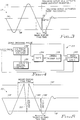
- FIG. 3 illustrates a portion of a TES signal 110 wherein a defect 112 occurs during the last half cycle of the signal. It is understood that a seek in an opposite direction would invert the polarity of the TES and its slope in the discussion to follow.
- one method of reducing the susceptibility of the optical recorder to noise and disk defects is to use three TES detectors (not shown). These detectors indicate when the TES crosses a zero reference point and the positive peaks and the negative peaks of TES. Two peaks of opposite polarities must be encountered before a track is counted.
- the TES signal 110 is sinusoidal whose positive peak exceeds a positive threshold 116 and whose negative peak exceeds a negative threshold 118.
- the positive and negative peaks of TES signal 110 must exceed the respective thresholds 116 and 118 in order to be considered a peak during a seek operation. Moreover, the TES signal 110 normally crosses a zero reference point 114 between positive and negative peaks. At the conclusion of a seek operation, a track servo (not shown) is activated to continue a track following operation on the desired track. Detail of the tracking circuits are disclosed in U.S. Patent 5,038,333. During the second half cycle of the last cycle of the TES signal 110, the defect 112 causes the detection of a negative pulse which exceeds the negative threshold 118 and could be interpreted as a zero crossing.
- the tracking servo normally activates after sequence of a positive pulse, a first zero crossing, a negative pulse and a second zero crossing. Moreover, if the tracking servo activates on an upward slope of the TES signal 110 after encountering the above sequence, it will be in a stable condition and will successfully lock onto the desired track. In view of the defect 112, the sequence includes a positive pulse, a first zero crossing, a negative pulse and a second zero crossing. However, the slope of the TES signal 110 is downward which cause an unstable condition when the tracking servo activates and causes a error in a subsequent track following operation.
- Fig. 4 shows a block diagram of a masking circuit 130 which eliminates the error caused by the defect 112 (FIG. 3) encountered during the last half cycle of the TES signal 110.
- Circuit 130 includes a half-track counter 132. Prior to a seek operation, counter 132 is loaded with a count value which is equal to the number of half-tracks between the present track and the desired track. For purposes of illustration and not limitation, if a seek operation to be executed involves a movement to a track which is two tracks away from the current track, the count value in counter 132 is set equal to a value of four which coincides to four half-tracks. Thereafter, counter 132 is decremented one count for each half-track of movement. As is shown in FIG.
- Circuit 130 further includes an AND gate 134 which receives an indication when the TES signal 110 performs a zero crossing and and input from a decoder/comparator 136. Comparator 136 compares the count value of the counter 132 with a value of one. Gate 134 is coupled to a timer circuit 138. The timer circuit 138 is coupled to the seek control logic 140. The details of the timer circuit and the seek control logic are known in the art and will not be discussed here.
- the timer circuit 138 is activated upon the occurrence of the next-to-last zero crossing of the TES signal 110 and a count value of one in the counter 132.
- the next-to-last zero crossing of the TES signal 110 occurs when the count value of the counter 132 equals a value of one and zero crossing of the TES signal occurs.
- the activation of timer circuit 138 facilitates the blocking of the final zero crossing point of the TES signal 110 for a predetermined time.
- the timer circuit 138 must have a time interval which is equal to the time required to reach a last peak immediately prior to the required time to terminate the seek operation.
- FIG. 5 illustrates a TES signal 110′ wherein a defect 150 occurs in the first half cycle and a defect 152 occurs during the second half cycle of the signal.
- the TES signal 110′ is sinusoidal whose positive peak exceed a positive threshold 116′ and whose negative peak exceed a negative threshold 118′.
- the positive and negative peaks of TES signal 110′ must exceed the respective thresholds 116′ and 118 in order to be considered a peak during a seek operation.
- the TES signal 110′ normally crosses a zero reference point 114′ between positive and negative peaks.
- defect 150 is slightly different from defect 112, the same techniques can be used to resolve the media defect condition. As illustrated in FIG. 5, defect 150 goes beyond the threshold point 118′ and would appear as a true track crossing.
- the normal seek algorithm would be fooled into activating the tracking servo on the wrong slope of the TES signal 110′.
- it can be predicted, using a masking circuit similar to circuit 130, that the last peak caused by defect 150 comes well before the predicted time.
- FIG. 6 illustrates a block diagram of a masking circuit 160 which eliminates the errors caused by the defects 150 and 152 (FIG. 5).
- Circuit 160 includes a half-track counter 132′.
- counter 132′ Prior to a seek operation, counter 132′ is loaded with a count value which is equal to the number of half-tracks between the present track and the desired track. For purposes of illustration and not limitation, if a seek operation to be executed involves a movement to a track which is two tracks away from the current track, the count value in counter 132′ is set equal to a value of four which coincides to four half-tracks. Thereafter, counter 132′ is decremented one count for each half-track of movement.
- Circuit 160 further includes an AND gate 134′ which receives an indication when the TES signal 110′ performs a zero crossing and an input from a decoder/comparator 136′. Comparator 136′ compares the count value of the counter 132′ with values of one and two.
- AND gate 134′ is coupled to a first timer circuit 138′.
- the first timer circuit 138′ is coupled an input of an AND gate 139.
- AND gates 134′ and 139 each receive an input from the comparator 136 and an indication when a zero crossing has occurred.
- AND gate 139′ is coupled to a second timer circuit 144.
- the second timer circuit 144 is coupled to the seek control logic 148.
- the details of the timer circuits 138′ and 144, and the seek control logic 148 are known in the art and will not be discussed here.
- the first timer circuit 138′ is activated upon the occurrence of the zero crossing of the TES signal 110′ and when the count value of the half-track counter 132′ equals two.
- the count value of two in the half-track counter 132′ represents either the first half cycle of the TES signal 110′ if the destination track is the next adjacent track or the first half cycle of the last track prior to the destination track.
- the activation of the first timer circuit 138′ facilitates the blocking of the defect 150 of the TES signal 110′ for a predetermined time.
- the first timer circuit 138′ must have a time interval which is equal to the time required to reach beyond the expected passing of threshold 116′ but prior to the next-to-last zero crossing point 145 (FIG.5).
- the first timer 138′ When the first timer 138′ has timed-out, it sends a signal to AND gate 139.
- the second timer circuit 144 Upon the occurrence of a count value of one in the half-track counter 136′ and that of the next-to-last zero crossing point, the second timer circuit 144 is activated to mask out the defect 152 in a similar manner set forth above for defect 112.
- FIG. 7 is a flow chart which illustrates the steps utilized in masking out media defects encountered during a seek operation in accordance with the present invention.
- the half-track counter 132 or 132′ are loaded with the appropriate count value reflective of the number of half-tracks between the current track and the destination or desired track.
- Step 172 determines whether a first peak has been detected.
- Step 174 decrements the half-track counter 132 or 132′ subsequent to the detection of the first peak.
- Step 176 determines whether a second peak has been detected and whether the first mask procedure has not been activated.
- Step 178 facilitates the decrementing of the half-track counter 132 or 132′ in response to the second peak being detected and the first mask procedure not being activated.
- Step 180 determines whether the half-track counter 132 or 132′ has reached a count of zero.
- Step 182 determines whether the second mask procedure is activated and whether there has been a zero crossing. If the second mask procedure is not activated and there is a zero crossing, the seek operation is completed and a track following operation is initiated in step 184.
Abstract
Description
- The present invention relates to position control system, particularly but not exclusively those position systems being advantageously used with optical disk recorders.
- Both magnetic and optical disk recorders employ either a large plurality of concentric record tracks or a single spiraling record track. The tracks on optical disks are identified by any one of a plurality of surface configurations on the optical medium (disk). A common configuration is a disk-shaped medium having circularly concentric groove or a single spiral groove, for indicating the location of the record tracks. In both magnetic and optical disks recorders, means are provided for faithfully following one of the addressed record tracks. When it is desired to scan a track other than a currently scanned track. a track seek operation is provided; that is, the track following is aborted and a track seek algorithm is initiated which causes the effective disconnection of the track following operation.
- When seeking from one track to another track, magnetic and optical recorder must keep track of its current track on the disk as well as the desired track. This is typically done using a tracking error signal (TES). Tracks are counted as a recording head is moved radially across the tracks between the current track and the desired track. As is well known in the art, during a seek operation, a light beam is moved along with the recording head radially across the tracks. As the light beam moves across the tracks, the TES appears as a sinusoidal or substantial sinusoidal waveform. The peaks of TES are produced at the cliffs between the tracks and grooves or the disk surface. In this manner, the tracks are one full cycle apart.
- The simplest method of determining position from the TES is to produce a pulse whenever the TES crosses a zero reference point and then count these pulses. This method, however, is susceptible to miscounting due to noise and disk defects. A superior method, which is used today, utilizes a plurality of TES detectors to indicate zero crossing points and positive and negative peaks. Two peaks of opposite polarities must be encountered before a track crossing is counted. This method allows for greater noise tolerance on the TES. However, media defects can still occasionally result in either the seek operation being too long, i.e. it missed counting a track, or the seek being too short, i.e. counting a defect as a track. As is known in the art, both of these conditions can be recovered from quickly and easily.
- The only time a defect can cause a serious problem is when it occurs at the end of the seek operation when a tracking servo is activated. The tracking servo attempts to maintain the TES at the zero reference point. If the tracking servo is activated on a upward slope of the TES when the seeking operation is in a direction toward an outer edge of the disk, the tracking servo will lock on the target track. If, however, the tracking servo is activated on the downward slope, the TES would be opposite to what is needed for a stable condition. Thus, the recording head will "skate" over the disk. In essence, the head will move at an accelerated pace during the downward slope and decelerate over the upward slope. As a result of this activity, a time consuming recovery procedure must activated to stop the skating motion and to lock on the target track. Thus, it is important to activate the tracking servo on the correct slope after a seek operation.
- U. S. Patent 4,839,876 discloses an optical disk recorder which includes a position servo control loop for causing a beam of radiation to faithfully follow a track on the disk, jump from a current track to an adjacent track or to a small number of tracks away from the current track. Operation of the position servo loop is altered by selectively reversing the phase of a differentiated position error signal and integrating the differentiated position error signal for comparison with a sawtooth signal for moving the beam of radiation from the current track to an immediately adjacent track under continuous position servo control. Upon reaching the adjacent track, the sawtooth signal returns to a reference potential for initiating track following. The servo error signal and the sawtooth signal does not cause any significant perturbations in the positioning servo loop operation. This patent does not address the problem encountering media defects during a seek operation.
- U. S. Patent 5,038,333 discloses a track-seeking apparatus of a disk recorder which employs a track-crossing sensor to produce track-crossing signals. An oscillator is slaved to the sensor for supplying substitute track-crossing pulses in the absence of the sensor providing such pulses or when the radial velocity exceeds a threshold velocity. A velocity profile means alters the oscillator frequency so that the oscillator produces track-crossing pulses in accordance with the profile. This patent does not address the problem of the encountering media defects during a seek operation.
- U. S. Patent 5,001,732 discloses a track counter for optical disk which counts the number of tracks a light beam passes upon when an optical head moves over an optical disk in a radial direction. The track counter includes a passage signal generating circuit which generates a signal each time the reflected light of the the light beam passes over a track. A counter counts the signals generated by the passage signal generating circuit. A counter suspending circuit determines that the light beam will pass over a specific position of a track and suspends the action of the counter for a predetermined period of time. A count value compensating circuit assumes the number of tracks the light beam passed during the predetermined period of time and adds this assumed number to the count value of the counter. This invention address problems on the disk in designated areas. It does not address the problem of encountering media defects which may occur in areas other than the designated areas.
- Accordingly, it is desired to provide for a drive which is less susceptible to poor optical media quality and provides for more reliability during seek operations.
- Viewed from one aspect the present invention provides a data processing system including disk drive storage apparatus, the disk drive storage apparatus comprising at least one head for transferring data between a disk loaded in the disk drive and the data processing system; means for producing a tracking error signal corresponding to the position of one of the heads relative to a disk loaded in the disk drive; means for determining when a selected portion of the tracking error signal occurs; means for detecting when the error signal crosses a predetermined reference point; means, responsive to the determining and the detecting means, for masking abnormalities within the selected portion of the tracking error signal during a seek operation of the head.
- Viewed from another aspect the present invention provides a machine-effected method of masking tracking error signal abnormalities due to disk media defects encountered during a head seek operation in a disk drive comprising the steps of: determining when a first selected portion of the tracking error signal occurs; detecting when the tracking error signal crosses a predetermined reference point; masking defects within the first selected portion of the tracking error signal in response to the first selected portion determining and the detecting steps; determining when a second selected portion of the tracking error signal will occur; and masking defects within the second selected portion of the tracking error signal in response to the second selected portion determining and the detecting steps.
- In an optical disk recorder, during the sensing of closely-spaced, position-indicating, machine-sensible indicia, a first peak of a track error signal is detected. In response to the first peak being detected, a half-track counter is decremented from a value which depends upon the position of the destination track relative to a current track. In response to the occurrence of a selected value of the half-track counter and the presence of a zero crossing of the tracking error signal, a first timer is activated to mask any defects occurring during the selected first half cycle of the last cycle of the tracking error signal. The half-track counter is again decremented in response to a second peak being detected and the occurrence of a next-to-last zero crossing of the tracking error signal and a second timer is then activated to mask any subsequent defects occurring during the second half cycle of the tracking error signal. The seek operation is terminated when the count value in the half-track counter equals zero and a final zero crossing is detected. Thereafter, a track following operation is activated.
- In order that the invention may be fully understood preferred embodiments thereof will now be described, by way of example only, with reference to the accompanying drawings in which:
- FIG. 1 is a simplified block diagram of an optical disk recorder/player in accordance with the present invention;
- FIG. 2 spatially illustrates the relationship of tracks and tracking error signals;
- FIG. 3 is a waveform illustrating a defect occurring during a second half cycle of the last cycle of a tracking error signal;
- FIG. 4 is a block diagram of a circuit for masking the type of defect shown in FIG. 3 in accordance with the present invention;
- FIG. 5 is a waveform illustrating a defect occurring during the first and second half cycles of the last cycle of a tracking error signal;
- FIG. 6 is a block diagram of a circuit for masking the types of defects shown in FIG. 5 in accordance with the present invention; and
- FIG. 7 is a flow chart illustrating the steps utilized in masking the defects shown in FIGS. 3 and 5.
- Referring now more particularly to the appended drawing, like numerals indicate like structural parts and features in the various figures. An optical recorder with which the present invention may be advantageously employed is shown in Fig. 1. A magneto-
optic record disk 30 is mounted onspindle 31 for rotation bymotor 32. Optical head-carryingarm 33 on head-arm carriage generally denoted bynumeral 34, moves radially ofdisk 30. Aframe 35 of recorder suitably mountscarriage 34 for reciprocating radial motions. The radial motions ofcarriage 34 enable access to any one of a plurality of concentric tracks or circumvolutions of a spiral track for recording and recovering data on and from the disk.Linear actuator 36 suitably mounted onframe 35, radially movescarriage 34 for enabling track accessing. The recorder is suitably attached to one ormore host processors 37, such host processors may be control units, personal computers, large system computers, communication systems, image process processors, and the like. Attachingcircuits 38 provide the logical and electrical connections between the optical recorder and the attachinghost processors 37. -
Microprocessor 40 controls the recorder including the attachment to thehost processor 37. Control data, status data, commands and the like are exchanged between attachingcircuits 38 andmicroprocessor 40 viabidirectional bus 43. Included in micro-processor 40 is a program or microcode storing, read-only memory (ROM) 41 and a data and control signal storing random access memory (RAM) 42. - The optics of the recorder include an objective or focusing
lens 45 mounted for focusing and tracking motions on head-arm 33 byfine actuator 46. This actuator includes mechanisms for movinglens 45 toward and away fromdisk 30 for focusing and for radial movements parallel tocarriage 34 motions; for example, for changing tracks within a range of 100 tracks so thatcarriage 34 need not be actuated each time a track adjacent to a track currently being accessed is to be accessed.Numeral 47 denotes a two-way light path betweenlens 45 anddisk 30. - In magneto optic recording, magnet 48 (in a constructed
embodiment magnet 48 is an electromagnet) provides a weak magnetic steering field for directing the remnant magnetization direction of a small spot ondisk 30 illuminated by laser light fromlens 45. The laser light spot heats the illuminated spot on the record disk to a temperature above the Curie point of the magneto-optic layer (not shown, but can be an alloy of rare earth and transitional metals as taught by Chaudhari et al., US Patent 3,949,387). This heating enablesmagnet 48 to direct the remnant magnetization to a desired direction of magnetization as the spot cools below the Curie point temperature.Magnet 48 is shown as oriented in the "write" direction, i.e., binary ones recorded ondisk 30 normally are "north pole remnant magnetization". To erasedisk 30,magnet 48 rotates so the south pole isadjacent disk 30.Magnet 48control 49, which is mechanically coupled torotatable magnet 48 as indicated by dashedline 50, controls the write and erase directions.Microprocessor 40 supplies control signals overline 51 to control 49 for effecting reversal of the recording direction. - It is necessary to control the radial position of the
beam following path 47, such that a track or circumvolution is faithfully followed and that a desired track or circumvolution is quickly and precisely accessed. To this end, focus and tracking circuits 54 control both thecoarse actuator 36 andfine actuator 46. The positioning ofcarriage 34 byactuator 36 is precisely controlled by control signals supplied by circuits 54 over line 55 toactuator 36. Additionally, circuits 54 control signals travel overlines fine actuator 46.Lines actuator 46.Sensor 56 senses the relative position offine actuator 46 to head-arm carriage 33. - The focus and tracking position sensing is achieved by analyzing laser light reflected from
disk 30 overpath 47, thence throughlens 45, through one-half mirror 60 and to be reflected by half-mirror 61 to a so-called "quad detector" 62.Quad detector 62 has four photo elements which respectively supply signals on four lines collectively denominated by numeral 63 to focus and tracking circuits 54. Aligning one axis of thedetector 62 with a track centre line, track following operations are enabled. Focusing operations are achieved by comparing the light intensities detected by the four photo elements in thequad detector 62. Focus and tracking circuits 54 analyze the signals onlines 63 to control both focus and tracking. - Recording or writing data onto
disk 30 is next described. It is assumed thatmagnet 48 is rotated to the desired position for recording data.Microprocessor 40 supplies a control signal over line 65 tolaser control 66 for indicating that a recording operation is to ensue. This means that laser 67 is energized bycontrol 66 to emit a high-intensity, laser light beam for recording; in contrast, for reading, the laser 67 emitted laser light beam is a reduced intensity for not heating the laser illuminated spot ondisk 30 above the Curie point.Control 66 supplies its control signal overline 68 to laser 67 and receives a feedback signal overline 69 indicating the laser 67 emitted light intensity.Control 68 adjusts the light intensity to the desired value. Laser 67, a semiconductor laser such as a gallium arsenide diode laser, can be modulated by data signals so the emitted light beam represents the data to be recorded by intensity modulation. In this regard, data circuits 75 (later described) supply data-indicating signals overline 78 to laser 67 for effecting such modulation. This modulated light beam passes through polarizer 70 (linearly polarizing the beam), thence through collimatinglens 71 toward half mirror 60 for being reflected towarddisk 30 throughlens 45. Data circuits 75 are prepared for recording by the micro-processor 40 supplied control signals overline 76. Micro-processor 40 in preparing circuits 75 is responding to commands for recording received from ahost processor 37 via attachingcircuits 38. Once data circuits 75 are prepared, data is transferred directly betweenhost processor 37 to data circuits 75 through attachingcircuits 38. Data circuits 75 also includes ancillary circuits (not shown) relating todisk 30 format signals, error detection and correction and the like. Circuits 75, during a read or recovery action, strip the ancillary signals from the readback signals before supply corrected data signals overbus 77 to hostprocessor 37 via attaching to 38. - Reading or recovering data from
disk 30 for transmission to a host processor requires optical and electrical processing of the laser light beam from thedisk 30. That portion of the reflected light (which has its linear polarization frompolarizer 70 rotated bydisk 30 recording using the Kerr effect) travels along the two-waylight path 47, throughlens 45 and half-mirrors 60 and 61 to thedata detection portion 79 of the head-arm 33 optics. Half-mirror or beam splitter 80 divides the reflected beam into two equal intensity beams both having the same reflected rotated linear polarization. The half-mirror 80 reflected light travels through afirst polarizer 81, which is set to pass only that reflected light which was rotated when the remnant magnetization ondisk 30 spot being accessed has a "north" or binary one indication. This passed light impinges onphoto cell 82 for supplying a suitable indicating signal todifferential amplifier 85. When the reflected light was rotated by a "south" or erased pole direction remnant magnetization, then polarizer 81 passes no or very little light resulting in no active signal being supplied byphotocell 82. The opposite operation occurs bypolarizer 83 which passes only "south" rotated laser light beam tophoto cell 84.Photocell 84 supplies its signal indicating its received laser light to the second input ofdifferential amplifier 85. Theamplifier 85 supplies the resulting difference signal (data representing) to data circuits 75 for detection. The detected signals include not only data that is recorded but also all of the so-called ancillary signals as well. The term "data" as used herein is intended to include any and all information-bearing signals, preferably of the digital or discrete value type. - The rotational position and rotational speed of
spindle 31 is sensed by a suitable tachometer oremitter sensor 90.Sensor 90, preferably of the optical sensing type that senses dark and light spots on a tachometer wheel (not shown) ofspindle 31, supplies the "tach" signals (digital signals) toRPS circuit 91 which detects the rotational position ofspindle 31 and supplies rotational information-bearing signals tomicroprocessor 40.Microprocessor 40 employs such rotational signals for controlling access to data storing serpents ondisk 30 as is widely practised in the magnetic data storing disks. Additionally, thesensor 90 signals also travel to spindlespeed control circuits 93 for controllingmotor 32 to rotatespindle 31 at a constant rotational speed.Control 93 may include a crystal controlled oscillator for controllingmotor 32 speed, as is well known.Microprocessor 40 supplies control signals overline 94 to control 93 in the usual manner. - Referring to FIG. 2, a portion of the information-bearing surface of
disk 30 is illustrated. Thedisk 30 is formed with two sets of concentric rings, one set being tracks ormesas 100 and the secondset being grooves 102. When thelight beam 47 is focused into agroove 102, the TES is at a zerocrossing position 104, i.e. when exactly centered, the sensed TES should be at zero. As thelight beam 47 moves from one track to another track, the amplitude of TES changes as a sinusoid with the direction of change indicating the direction of tracking error. As thelight beam 47 scans transversely (radially) across thetracks 100 orgrooves 102, TES takes the sinusoidal shape wherein zero axis crossings in a first direction signify crossing the centre of the grooves. Similarly, when thelight beam 47 is crossing thetracks 100, the zero access crossing of TES is in the opposite direction. In essence, the peaks of TES are produced at the cliffs between thetracks 100 and thegrooves 102 on the surface of thedisk 30. - FIG. 3 illustrates a portion of a
TES signal 110 wherein adefect 112 occurs during the last half cycle of the signal. It is understood that a seek in an opposite direction would invert the polarity of the TES and its slope in the discussion to follow. As stated above, one method of reducing the susceptibility of the optical recorder to noise and disk defects is to use three TES detectors (not shown). These detectors indicate when the TES crosses a zero reference point and the positive peaks and the negative peaks of TES. Two peaks of opposite polarities must be encountered before a track is counted. Further as noted above, theTES signal 110 is sinusoidal whose positive peak exceeds a positive threshold 116 and whose negative peak exceeds anegative threshold 118. The positive and negative peaks of TES signal 110 must exceed therespective thresholds 116 and 118 in order to be considered a peak during a seek operation. Moreover, the TES signal 110 normally crosses a zero reference point 114 between positive and negative peaks. At the conclusion of a seek operation, a track servo (not shown) is activated to continue a track following operation on the desired track. Detail of the tracking circuits are disclosed in U.S. Patent 5,038,333. During the second half cycle of the last cycle of theTES signal 110, thedefect 112 causes the detection of a negative pulse which exceeds thenegative threshold 118 and could be interpreted as a zero crossing. The tracking servo normally activates after sequence of a positive pulse, a first zero crossing, a negative pulse and a second zero crossing. Moreover, if the tracking servo activates on an upward slope of theTES signal 110 after encountering the above sequence, it will be in a stable condition and will successfully lock onto the desired track. In view of thedefect 112, the sequence includes a positive pulse, a first zero crossing, a negative pulse and a second zero crossing. However, the slope of theTES signal 110 is downward which cause an unstable condition when the tracking servo activates and causes a error in a subsequent track following operation. - Fig. 4 shows a block diagram of a
masking circuit 130 which eliminates the error caused by the defect 112 (FIG. 3) encountered during the last half cycle of theTES signal 110.Circuit 130 includes a half-track counter 132. Prior to a seek operation,counter 132 is loaded with a count value which is equal to the number of half-tracks between the present track and the desired track. For purposes of illustration and not limitation, if a seek operation to be executed involves a movement to a track which is two tracks away from the current track, the count value incounter 132 is set equal to a value of four which coincides to four half-tracks. Thereafter,counter 132 is decremented one count for each half-track of movement. As is shown in FIG. 3, one half-track is equal to one half cycle of theTES signal 110.Circuit 130 further includes an ANDgate 134 which receives an indication when theTES signal 110 performs a zero crossing and and input from a decoder/comparator 136.Comparator 136 compares the count value of thecounter 132 with a value of one.Gate 134 is coupled to atimer circuit 138. Thetimer circuit 138 is coupled to the seek control logic 140. The details of the timer circuit and the seek control logic are known in the art and will not be discussed here. - In operation, during a seek operation, the optical recorder will always arrive at the destination or desired track with a constant velocity plus or minus some tolerance. Thus, any defect that may occur during the downward slope of the last peak can be masked out. The
timer circuit 138 is activated upon the occurrence of the next-to-last zero crossing of theTES signal 110 and a count value of one in thecounter 132. The next-to-last zero crossing of theTES signal 110 occurs when the count value of thecounter 132 equals a value of one and zero crossing of the TES signal occurs. The activation oftimer circuit 138 facilitates the blocking of the final zero crossing point of the TES signal 110 for a predetermined time. Thetimer circuit 138 must have a time interval which is equal to the time required to reach a last peak immediately prior to the required time to terminate the seek operation. - FIG. 5 illustrates a
TES signal 110′ wherein adefect 150 occurs in the first half cycle and adefect 152 occurs during the second half cycle of the signal. The TES signal 110′ is sinusoidal whose positive peak exceed a positive threshold 116′ and whose negative peak exceed anegative threshold 118′. The positive and negative peaks of TES signal 110′ must exceed the respective thresholds 116′ and 118 in order to be considered a peak during a seek operation. Moreover, the TES signal 110′ normally crosses a zero reference point 114′ between positive and negative peaks. Althoughdefect 150 is slightly different fromdefect 112, the same techniques can be used to resolve the media defect condition. As illustrated in FIG. 5,defect 150 goes beyond thethreshold point 118′ and would appear as a true track crossing. With this condition, the normal seek algorithm would be fooled into activating the tracking servo on the wrong slope of the TES signal 110′. Moreover, as set forth above, in view of the constant and predictable velocity (within a specific tolerance) at the end of the seek opera tion, it can be predicted, using a masking circuit similar tocircuit 130, that the last peak caused bydefect 150 comes well before the predicted time. - FIG. 6 illustrates a block diagram of a
masking circuit 160 which eliminates the errors caused by thedefects 150 and 152 (FIG. 5).Circuit 160 includes a half-track counter 132′. Prior to a seek operation, counter 132′ is loaded with a count value which is equal to the number of half-tracks between the present track and the desired track. For purposes of illustration and not limitation, if a seek operation to be executed involves a movement to a track which is two tracks away from the current track, the count value incounter 132′ is set equal to a value of four which coincides to four half-tracks. Thereafter, counter 132′ is decremented one count for each half-track of movement.Circuit 160 further includes an ANDgate 134′ which receives an indication when the TES signal 110′ performs a zero crossing and an input from a decoder/comparator 136′.Comparator 136′ compares the count value of thecounter 132′ with values of one and two. ANDgate 134′ is coupled to afirst timer circuit 138′. Thefirst timer circuit 138′ is coupled an input of an ANDgate 139. ANDgates 134′ and 139 each receive an input from thecomparator 136 and an indication when a zero crossing has occurred. ANDgate 139′ is coupled to asecond timer circuit 144. Thesecond timer circuit 144 is coupled to the seekcontrol logic 148. The details of thetimer circuits 138′ and 144, and the seekcontrol logic 148 are known in the art and will not be discussed here. - In operation, during a seek operation, the optical recorder will always arrive at the destination or desired track with a constant velocity plus or minus some tolerance. Thus, any defect that may occur during the downward slope of the last peak can be masked out. The
first timer circuit 138′ is activated upon the occurrence of the zero crossing of the TES signal 110′ and when the count value of the half-track counter 132′ equals two. The count value of two in the half-track counter 132′ represents either the first half cycle of the TES signal 110′ if the destination track is the next adjacent track or the first half cycle of the last track prior to the destination track. The activation of thefirst timer circuit 138′ facilitates the blocking of thedefect 150 of the TES signal 110′ for a predetermined time. Thefirst timer circuit 138′ must have a time interval which is equal to the time required to reach beyond the expected passing of threshold 116′ but prior to the next-to-last zero crossing point 145 (FIG.5). When thefirst timer 138′ has timed-out, it sends a signal to ANDgate 139. Upon the occurrence of a count value of one in the half-track counter 136′ and that of the next-to-last zero crossing point, thesecond timer circuit 144 is activated to mask out thedefect 152 in a similar manner set forth above fordefect 112. - FIG. 7 is a flow chart which illustrates the steps utilized in masking out media defects encountered during a seek operation in accordance with the present invention. In
step 170, prior to initiating the seek operation, the half-track counter track counter track counter track counter step 184. - While the invention has been particularly shown and described with reference to preferred embodiment thereof, it will be understood by those skilled in the art that various changes in form and details may be made therein without departing from the scope of the invention.
Claims (10)
- A data processing system including disk drive storage apparatus, the disk drive storage apparatus comprising:
at least one head for transferring data between a disk loaded in the disk drive and the data processing system;
means for producing a tracking error signal corresponding to the position of one of the heads relative to a disk loaded in the disk drive;
means for determining when a selected portion of the tracking error signal occurs;
means for detecting when the error signal crosses a predetermined reference point;
means, responsive to the determining and the detecting means, for masking abnormalities within the selected portion of the tracking error signal during a seek operation of the head. - A data processing system as claimed in claim 1 wherein the determining means includes means for counting the number of tracks between a current track of a disk laoded in the disk drive and a destination track.
- A data processing system as claimed in claim 2 further comprising means for comparing a count value of the counting means with a predetermined value.
- A data processing system as claimed in any of the preceding claims wherein the predetermined reference point is a zero crossing point.
- A data processing system as claimed in any of the preceding claims wherein the masking means is activated for a selected period of time.
- A data processing system as claimed in any of the preceding claims comprising means for terminating the seek operation.
- A data processing system as claimed in claim 6 wherein the terminating means includes means for determining when the counting means has a zero count value, a zero crossing of the error signal has occurred and the masking means is not activated.
- A machine-effected method of masking tracking error signal abnormalities encountered during a head seek operation in a disk drive comprising the steps of:
determining when a first selected portion of the tracking error signal occurs;
detecting when the tracking error signal crosses a predetermined reference point;
masking defects within the first selected portion of the tracking error signal in response to the first selected portion determining and the detecting steps;
determining when a second selected portion of the tracking error signal will occur; and
masking defects within the second selected portion of the tracking error signal in response to the second selected portion determining and the detecting steps. - A method as claimed in claim 8 wherein the determining step counts the number of half tracks between a current track and a destination track.
- A method as claimed in any of claims 8 or 9 further comprising the step of comparing a count value of the counter with a predetermined value.
Applications Claiming Priority (2)
| Application Number | Priority Date | Filing Date | Title |
|---|---|---|---|
| US78065491A | 1991-10-18 | 1991-10-18 | |
| US780654 | 1991-10-18 |
Publications (2)
| Publication Number | Publication Date |
|---|---|
| EP0538025A2 true EP0538025A2 (en) | 1993-04-21 |
| EP0538025A3 EP0538025A3 (en) | 1993-05-19 |
Family
ID=25120241
Family Applications (1)
| Application Number | Title | Priority Date | Filing Date |
|---|---|---|---|
| EP19920309395 Withdrawn EP0538025A3 (en) | 1991-10-18 | 1992-10-15 | Disk drive |
Country Status (3)
| Country | Link |
|---|---|
| US (1) | US5426625A (en) |
| EP (1) | EP0538025A3 (en) |
| JP (1) | JPH05205416A (en) |
Cited By (1)
| Publication number | Priority date | Publication date | Assignee | Title |
|---|---|---|---|---|
| SG80591A1 (en) * | 1998-04-25 | 2001-05-22 | Texas Instr Singapore Pte Ltd | Track counter |
Families Citing this family (22)
| Publication number | Priority date | Publication date | Assignee | Title |
|---|---|---|---|---|
| US5543697A (en) * | 1994-10-27 | 1996-08-06 | Sgs-Thomson Microelectronics, Inc. | Circuit and method for controlling the speed of a motor |
| JP2842358B2 (en) * | 1996-02-13 | 1999-01-06 | 日本電気株式会社 | Track count device for optical disk |
| KR100280868B1 (en) * | 1996-05-09 | 2001-02-01 | 윤종용 | Track Cross Signal Correction Device |
| JPH1091971A (en) * | 1996-09-12 | 1998-04-10 | Sony Corp | Tracking controller and method for optical disk device |
| JPH1091983A (en) * | 1996-09-12 | 1998-04-10 | Sony Corp | Optical disk device and tracking error signal calculating circuit |
| US6011772A (en) | 1996-09-16 | 2000-01-04 | Spectradisc Corporation | Machine-readable optical disc with reading-inhibit agent |
| US6747930B1 (en) | 1996-12-24 | 2004-06-08 | Hide & Seek Technologies, Inc. | Data protection on an optical disk |
| US6338933B1 (en) | 1998-06-25 | 2002-01-15 | Spectradisc Corporation | Methods and apparatus for rendering an optically encoded medium unreadable |
| US6531262B1 (en) | 1998-06-25 | 2003-03-11 | Spectradisc Corporation | Methods and apparatus for rendering an optically encoded medium unreadable and tamper-resistant |
| JP2000113614A (en) * | 1998-10-09 | 2000-04-21 | Sony Corp | Drive device and constant-speed movement servo method |
| JP4243059B2 (en) * | 1999-07-12 | 2009-03-25 | フレックスプレイ・テクノロジーズ・インコーポレイテッド | Single-use optical storage medium and manufacturing method thereof |
| JP3808683B2 (en) * | 2000-03-01 | 2006-08-16 | 三菱電機株式会社 | Optical disk device |
| US20050063256A1 (en) * | 2000-06-30 | 2005-03-24 | Selinfreund Richard H. | Data storage in optical discs |
| WO2002002301A1 (en) | 2000-06-30 | 2002-01-10 | Verification Technologies Inc. | Copy-protected optical media and method of manufacture thereof |
| US6638593B2 (en) | 2000-06-30 | 2003-10-28 | Verification Technologies, Inc. | Copy-protected optical media and method of manufacture thereof |
| US7660415B2 (en) | 2000-08-03 | 2010-02-09 | Selinfreund Richard H | Method and apparatus for controlling access to storage media |
| US6982109B2 (en) * | 2000-12-11 | 2006-01-03 | Flexplay Technologies, Inc. | Method for rendering surface layer of limited play disk lightfast |
| TW509913B (en) * | 2001-03-21 | 2002-11-11 | Via Tech Inc | Optical disk driver tracking method |
| AU2002305849B2 (en) * | 2001-06-05 | 2008-01-17 | Flexplay Technologies, Inc. | Limited play optical devices with interstitial reactive layer and methods of making same |
| TW594694B (en) | 2002-09-13 | 2004-06-21 | Mediatek Inc | Method for counting number of tracks of an optical disc in an optical disc system |
| TWI229331B (en) * | 2003-10-22 | 2005-03-11 | Mediatek Inc | Compensation method for detecting seeking speed of optical disk device |
| US7830756B2 (en) * | 2004-09-08 | 2010-11-09 | Lsi Corporation | Demodulation of tracking error signal to obtain lens position for lens motion control in an optical disc system |
Citations (8)
| Publication number | Priority date | Publication date | Assignee | Title |
|---|---|---|---|---|
| EP0277793A2 (en) * | 1987-02-02 | 1988-08-10 | Sony Corporation | Access control apparatus |
| JPS6423472A (en) * | 1987-07-20 | 1989-01-26 | Oki Electric Ind Co Ltd | Track seek device |
| JPS6427084A (en) * | 1987-07-23 | 1989-01-30 | Canon Kk | Track access method for information recording and reproducing device |
| JPH01276474A (en) * | 1988-04-27 | 1989-11-07 | Olympus Optical Co Ltd | Track retrieval control device for information recording and reproducing device |
| JPH01277378A (en) * | 1988-04-28 | 1989-11-07 | Olympus Optical Co Ltd | Track cross signal counter |
| EP0437891A1 (en) * | 1990-01-19 | 1991-07-24 | Koninklijke Philips Electronics N.V. | Read and/or write device |
| US5042019A (en) * | 1987-08-07 | 1991-08-20 | Canon Kabushiki Kaisha | Method of and apparatus for seeking a desired track by counting track crossing signals which are detected within a predetermined time interval |
| EP0505252A2 (en) * | 1991-03-19 | 1992-09-23 | Fujitsu Limited | Method and circuit for correcting track zero-crossing signal in optical disk system |
Family Cites Families (12)
| Publication number | Priority date | Publication date | Assignee | Title |
|---|---|---|---|---|
| US4135217A (en) * | 1976-11-02 | 1979-01-16 | Xerox Corporation | Utilization of stored run-out information in a track following servo system |
| JPS5373121A (en) * | 1976-12-13 | 1978-06-29 | Fujitsu Ltd | Cylindrical pulse generating circuit |
| JPS5517877A (en) * | 1978-07-24 | 1980-02-07 | Nippon Telegr & Teleph Corp <Ntt> | Head positioning control system |
| US4414655A (en) * | 1981-03-31 | 1983-11-08 | Discovision Associates | Scanning beam control system |
| JPS5940378A (en) * | 1982-08-31 | 1984-03-06 | Toshiba Corp | Disk device |
| US4516178A (en) * | 1982-09-15 | 1985-05-07 | Ampex Corporation | Cylinder crossing detection circuit for disc drive or the like |
| JPS59145726U (en) * | 1983-03-16 | 1984-09-28 | パイオニア株式会社 | Servo device in information reading device |
| US4959823A (en) * | 1985-07-30 | 1990-09-25 | Laser Magnetic Storage International Company | Tracking and seeking system for use with an optical record carrier having a wobbled track format |
| DE3884824T2 (en) * | 1987-02-04 | 1994-02-10 | Matsushita Electric Ind Co Ltd | Object positioning system. |
| US4839876A (en) * | 1987-11-23 | 1989-06-13 | International Business Machines Corporation | Track seeking using a track following loop |
| JP2562195B2 (en) * | 1989-01-10 | 1996-12-11 | シャープ株式会社 | Optical disc track counter |
| US5038333A (en) * | 1989-05-05 | 1991-08-06 | International Business Machines Corporation | Positioning systems including reliable track crossing detection for high speed relative motions |
-
1992
- 1992-07-29 JP JP4202284A patent/JPH05205416A/en active Pending
- 1992-10-15 EP EP19920309395 patent/EP0538025A3/en not_active Withdrawn
-
1994
- 1994-05-31 US US08/252,141 patent/US5426625A/en not_active Expired - Fee Related
Patent Citations (8)
| Publication number | Priority date | Publication date | Assignee | Title |
|---|---|---|---|---|
| EP0277793A2 (en) * | 1987-02-02 | 1988-08-10 | Sony Corporation | Access control apparatus |
| JPS6423472A (en) * | 1987-07-20 | 1989-01-26 | Oki Electric Ind Co Ltd | Track seek device |
| JPS6427084A (en) * | 1987-07-23 | 1989-01-30 | Canon Kk | Track access method for information recording and reproducing device |
| US5042019A (en) * | 1987-08-07 | 1991-08-20 | Canon Kabushiki Kaisha | Method of and apparatus for seeking a desired track by counting track crossing signals which are detected within a predetermined time interval |
| JPH01276474A (en) * | 1988-04-27 | 1989-11-07 | Olympus Optical Co Ltd | Track retrieval control device for information recording and reproducing device |
| JPH01277378A (en) * | 1988-04-28 | 1989-11-07 | Olympus Optical Co Ltd | Track cross signal counter |
| EP0437891A1 (en) * | 1990-01-19 | 1991-07-24 | Koninklijke Philips Electronics N.V. | Read and/or write device |
| EP0505252A2 (en) * | 1991-03-19 | 1992-09-23 | Fujitsu Limited | Method and circuit for correcting track zero-crossing signal in optical disk system |
Non-Patent Citations (4)
| Title |
|---|
| PATENT ABSTRACTS OF JAPAN vol. 13, no. 203 (P-870)15 May 1989 & JP-A-01 023 472 ( OKI ELECTRIC IND. CO. LTD ) * |
| PATENT ABSTRACTS OF JAPAN vol. 13, no. 210 (P-872)17 May 1989 & JP-A-01 027 084 ( CANON KK ) * |
| PATENT ABSTRACTS OF JAPAN vol. 14, no. 48 (P-997)29 January 1990 & JP-A-01 276 474 ( OLYMPUS OPTICAL CO. LTD ) * |
| PATENT ABSTRACTS OF JAPAN vol. 14, no. 48 (P-997)7 November 1989 & JP-A-01 277 378 ( OLYMPUS OPTICAL CO. LTD ) * |
Cited By (1)
| Publication number | Priority date | Publication date | Assignee | Title |
|---|---|---|---|---|
| SG80591A1 (en) * | 1998-04-25 | 2001-05-22 | Texas Instr Singapore Pte Ltd | Track counter |
Also Published As
| Publication number | Publication date |
|---|---|
| EP0538025A3 (en) | 1993-05-19 |
| JPH05205416A (en) | 1993-08-13 |
| US5426625A (en) | 1995-06-20 |
Similar Documents
| Publication | Publication Date | Title |
|---|---|---|
| US5426625A (en) | Masking of tracking error signal abnormalities due to media defects | |
| US5060210A (en) | Controlling head seeking speed in disk storage units by limiting displacement of head with respect to its supporting headarm | |
| US5038333A (en) | Positioning systems including reliable track crossing detection for high speed relative motions | |
| US4774699A (en) | Method and apparatus for positioning a read head to a selected track on a record disc | |
| US5138594A (en) | Reducing amplitude variations of optical disk readback signals and increasing reliability of track-crossing counts | |
| US4736353A (en) | Disc accessing using coarse and fine actuators with the fine actuator locked during coarse actuator movement | |
| KR950013696B1 (en) | Disk recorder operating apparatus & ti's drive machine driving method | |
| EP0328501B1 (en) | Apparatus and method for acquiring focus in an optical system | |
| US5361245A (en) | Optical signal processing apparatus for detecting the direction of movement of an optical reading device relative to an optical disk | |
| EP0495530B2 (en) | Method for recovering information from a selected track on a record disc | |
| EP0646910A1 (en) | Optical storage device | |
| EP0375266A2 (en) | Optical disc recording and/or reproduction apparatus | |
| US4789972A (en) | Selectively controlling the erasure in a magneto-optic recording medium | |
| US4989194A (en) | Optical information processing method of driving auto-focusing and/or auto-tracking means in accordance with a stored servo signal when irradiation of a record medium with light beam is stopped, and apparatus therefor | |
| EP0310250B1 (en) | A removable record disk apparatus with rotational position control | |
| EP0167177B1 (en) | Method for recovering information from a selected track on a record disk | |
| US5361246A (en) | Optical information processing apparatus provided with means for detecting abnormality of focusing servo with a predetermined sensitivity | |
| JP2000293862A (en) | Optical storage device and focus servo control method | |
| US4916680A (en) | Magnetooptic recording member having selectively-reversed erasure directions in predetermined recording areas of the record member | |
| US5426627A (en) | Optical information recording/reproducing apparatus | |
| EP0479521B1 (en) | Operational mode control for data storage apparatus using storage disk | |
| US4937800A (en) | Method of recording using selective-erasure directions for magnetooptic record members | |
| JPH0140424B2 (en) | ||
| JPH06195902A (en) | Information recording and reproducing device and tracking control circuit for this device | |
| JPH04114322A (en) | Optical disk device |
Legal Events
| Date | Code | Title | Description |
|---|---|---|---|
| PUAI | Public reference made under article 153(3) epc to a published international application that has entered the european phase |
Free format text: ORIGINAL CODE: 0009012 |
|
| PUAL | Search report despatched |
Free format text: ORIGINAL CODE: 0009013 |
|
| AK | Designated contracting states |
Kind code of ref document: A2 Designated state(s): DE FR GB |
|
| AK | Designated contracting states |
Kind code of ref document: A3 Designated state(s): DE FR GB |
|
| 17P | Request for examination filed |
Effective date: 19930819 |
|
| 17Q | First examination report despatched |
Effective date: 19951219 |
|
| STAA | Information on the status of an ep patent application or granted ep patent |
Free format text: STATUS: THE APPLICATION IS DEEMED TO BE WITHDRAWN |
|
| 18D | Application deemed to be withdrawn |
Effective date: 19970501 |