EP0540177A2 - Information transmission method and apparatus - Google Patents
Information transmission method and apparatus Download PDFInfo
- Publication number
- EP0540177A2 EP0540177A2 EP19920308908 EP92308908A EP0540177A2 EP 0540177 A2 EP0540177 A2 EP 0540177A2 EP 19920308908 EP19920308908 EP 19920308908 EP 92308908 A EP92308908 A EP 92308908A EP 0540177 A2 EP0540177 A2 EP 0540177A2
- Authority
- EP
- European Patent Office
- Prior art keywords
- information
- codes
- amount
- unit time
- error
- Prior art date
- Legal status (The legal status is an assumption and is not a legal conclusion. Google has not performed a legal analysis and makes no representation as to the accuracy of the status listed.)
- Granted
Links
Images


Classifications
-
- H—ELECTRICITY
- H04—ELECTRIC COMMUNICATION TECHNIQUE
- H04L—TRANSMISSION OF DIGITAL INFORMATION, e.g. TELEGRAPHIC COMMUNICATION
- H04L1/00—Arrangements for detecting or preventing errors in the information received
- H04L1/004—Arrangements for detecting or preventing errors in the information received by using forward error control
- H04L1/0056—Systems characterized by the type of code used
- H04L1/0057—Block codes
-
- H—ELECTRICITY
- H04—ELECTRIC COMMUNICATION TECHNIQUE
- H04L—TRANSMISSION OF DIGITAL INFORMATION, e.g. TELEGRAPHIC COMMUNICATION
- H04L1/00—Arrangements for detecting or preventing errors in the information received
- H04L1/004—Arrangements for detecting or preventing errors in the information received by using forward error control
- H04L1/0041—Arrangements at the transmitter end
-
- H—ELECTRICITY
- H04—ELECTRIC COMMUNICATION TECHNIQUE
- H04N—PICTORIAL COMMUNICATION, e.g. TELEVISION
- H04N1/00—Scanning, transmission or reproduction of documents or the like, e.g. facsimile transmission; Details thereof
- H04N1/00095—Systems or arrangements for the transmission of the picture signal
-
- H—ELECTRICITY
- H04—ELECTRIC COMMUNICATION TECHNIQUE
- H04N—PICTORIAL COMMUNICATION, e.g. TELEVISION
- H04N1/00—Scanning, transmission or reproduction of documents or the like, e.g. facsimile transmission; Details thereof
- H04N1/32—Circuits or arrangements for control or supervision between transmitter and receiver or between image input and image output device, e.g. between a still-image camera and its memory or between a still-image camera and a printer device
- H04N1/333—Mode signalling or mode changing; Handshaking therefor
-
- H—ELECTRICITY
- H04—ELECTRIC COMMUNICATION TECHNIQUE
- H04N—PICTORIAL COMMUNICATION, e.g. TELEVISION
- H04N1/00—Scanning, transmission or reproduction of documents or the like, e.g. facsimile transmission; Details thereof
- H04N1/41—Bandwidth or redundancy reduction
- H04N1/411—Bandwidth or redundancy reduction for the transmission or storage or reproduction of two-tone pictures, e.g. black and white pictures
- H04N1/413—Systems or arrangements allowing the picture to be reproduced without loss or modification of picture-information
- H04N1/417—Systems or arrangements allowing the picture to be reproduced without loss or modification of picture-information using predictive or differential encoding
Definitions
- This invention relates to an information transmission method and apparatus, and more particularly, to an information transmission method and apparatus in which the transmission speed of information can be switched.
- FIG. 4 is a diagram schematically illustrating transmitted information whose amount per unit time T (seconds) (the data rate) equals N (bits).
- FIG. 4 illustrates a case in which the redundancy for the total amount of information N (bits) including an information-code portion 12 equals m, and the following amount of check codes per unit time T (seconds) equals mN (bits).
- FIG. 5 is a diagram schematically illustrating information to be transmitted per unit time in such a case.
- the above-described approach also has the problem that even though the redundancy is not changed, the correction capability may change when different error-correcting codes are used in accordance with the form of the error-correcting code.
- the present invention has been made in conideration of the above-described problems in the prior art.
- an information transmission method comprising the steps of transmitting information in units of a block including information codes and error-correcting check codes at one of a plurality of transmission speeds, and switching from one transmission speed to another by changing the number of blocks to be transmitted per unit time without changing the amount of information of the information codes and the amount of information of the error-correcting check codes within each block.
- the present invention relates to an information transmission apparatus comprising means for establishing a first transmission mode for transmitting a first predetermined number of blocks per unit time, each block including a predetermined amount of information codes and a predetermined amount of error-correcting check codes, and means for establishing a second transmission mode for transmitting a second predetermined number, different from the first predetermined number, per unit time of blocks including the predetermined amount of information codes and the predetermined amount of error-correcting check codes.
- FIG. 1 is a block diagram showing the schematic configuration of an image transmission apparatus to which the present invention is applied.
- FIG. 1 there is shown an input terminal 101 for image signals.
- An image signal input from the input terminal 101 is supplied to a quantization circuit 102.
- the quantization circuit 102 performs quantization in accordance with a quantization coefficient determined by transmission-speed information input from a transmission clock signal generation circuit 105 and information relating to the amount of encoded data input from a variable-length encoding circuit 103, so that the amount of data which are finally output is constant in units of each picture frame.
- the variable-length encoding circuit 103 performs variable-length encoding of information output from the quantization circuit 102 and supplies the encoded information to a data adding or synthesis circuit 106, and also outputs the information to the quantization circuit 102 for determining the quantization coefficient in accordance with the amount of data of the encoded information.
- the data synthesis circuit 106 divides the image information subjected to variable-length encoding into respective blocks for every predetermined amount of codes.
- An error-correcting code generation circuit 104 generates check codes and adds the generated check codes to each of the above-described blocks. Each block to which the check codes are added will be hereinafter termed a small block.
- the transmission clock signal generation circuit 105 supplies the data synthesis circuit 106 with a transmission clock signal whose frequency is switched in accordance with the transmission speed.
- the data synthesis circuit 106 changes the number of small blocks to be transmitted per unit time so that the desired transmission speed can be obtained in accordance with the transmission clock signal. It is thereby possible to supply a code string at the desired transmission speed to an output terminal 107.
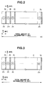
- FIG. 2 is a diagram schematically illustrating an information-code string to be transmitted in a unit time T (seconds) in a first mode in the image transmission apparatus shown in FIG. 1.
- reference numeral 1 indicates the total amount N (bits) of codes to be transmitted in the unit time T (seconds).
- the encoded image information is divided into n portions (2a - 2n shown in FIG. 2), one for each small block containing the predetermined amount of information codes.
- the total amount of codes in each of the divided small blocks equals N/n (bits).
- Check codes 3a - 3n for error correction whose amount is defined by a predetermined redundancy m are added to the respective small blocks.
- the amount of check codes in each small block equals mN/n (bits).
- FIG. 3 is a diagram schematically illustrating an information-code string to be transmitted per unit time T (seconds) in a second mode in the image transmission apparatus shown in FIG. 1, when the amount of codes to be transmitted per unit time T (seconds) is assumed to be kN (bits).
- reference numeral 4 indicates the total amount kN (bits) of codes to be transmitted in unit time T (seconds).
- the amount of check codes 3a - 3n in each small block is mN/n (bits).
- the amount of image information and the amount of information of check codes in each of the x divided small blocks are the same as in the first mode.
- the total amount of codes in each small block therefore equals N/n (bits).
- the desired transmission speed can be obtained by arranging that the value nk be an integer. Accordingly, by making the value n as large as possible, the degree of freedom increases for the value k. Consequently, the value k is not necessarily an integer.
- the amount of codes may be determined so that the total amount of codes to be transmitted becomes an integer multiple of the amount of codes in each block.
- the amount of information of information codes and the amount of information of check codes for error correction within a block do not change.
- the error correction capability does not have to change in any way even if the transmission speed is changed, and thus the problem in the prior art that the error correction capability changes when the transmission speed is changed is overcome.
- the size of the hardware does not increase since exactly the same error processing can be performed for different transmission speeds.
- encoded image information and check codes for error correction are alternately arranged
- the object of the present invention may, of course, be achieved no matter how they are arranged in the information transmission string, provided that all information in the information transmission strings 1 and 4 in FIGS. 2 and 3, respectively, can be transmitted in a unit time T (seconds).
Abstract
Description
- This invention relates to an information transmission method and apparatus, and more particularly, to an information transmission method and apparatus in which the transmission speed of information can be switched.
- FIG. 4 is a diagram schematically illustrating transmitted information whose amount per unit time T (seconds) (the data rate) equals N (bits).
- In FIG. 4, a hatched portion 11 represents check codes for error correction. FIG. 4 illustrates a case in which the redundancy for the total amount of information N (bits) including an information-
code portion 12 equals m, and the following amount of check codes per unit time T (seconds) equals mN (bits). - A case will now be considered in which the amount of information to be transmitted per unit time T (seconds) (transmission speed) is changed to kN (bits). FIG. 5 is a diagram schematically illustrating information to be transmitted per unit time in such a case.
- If it is assumed that the redundancy m is not changed for the purpose of not changing the error correction capability, the amount of check codes per unit time T (seconds) becomes kmN (bits), as shown in FIG. 5.
- In the above-described transmission format, therefore, the amount of check codes per unit time T (seconds) following the information codes is changed if the transmission speed is changed. Hence, it is necessary to change the form of the error-correcting code so as to be suitable for the amount of check codes.
- This results in providing different forms of error-correcting codes for different transmission speeds, causing difficulty in circuit design and an increase of the size of the hardware.
- The above-described approach also has the problem that even though the redundancy is not changed, the correction capability may change when different error-correcting codes are used in accordance with the form of the error-correcting code.
- The present invention has been made in conideration of the above-described problems in the prior art.
- It is an object of the present invention to provide an information transmission method and an information transmission apparatus in which common hardware can be used for transmission at different speeds while always maintaining a constant error correcting capability.
- This object is accomplished, according to one aspect of the present invention, by an information transmission method comprising the steps of transmitting information in units of a block including information codes and error-correcting check codes at one of a plurality of transmission speeds, and switching from one transmission speed to another by changing the number of blocks to be transmitted per unit time without changing the amount of information of the information codes and the amount of information of the error-correcting check codes within each block.
- According to another aspect, the present invention relates to an information transmission apparatus comprising means for establishing a first transmission mode for transmitting a first predetermined number of blocks per unit time, each block including a predetermined amount of information codes and a predetermined amount of error-correcting check codes, and means for establishing a second transmission mode for transmitting a second predetermined number, different from the first predetermined number, per unit time of blocks including the predetermined amount of information codes and the predetermined amount of error-correcting check codes.
- The foregoing and other objects, advantages and features of the present invention will become more apparent from the following detailed description of the preferred embodiment taken in conjunction with the accompanying drawings.
-
- FIG. 1 is a block diagram showing the schematic configuration of an image transmission apparatus according to an embodiment of the present invention;
- FIG. 2 is a diagram schematically illustrating an information-code string to be transmitted per unit time in a first mode in the image transmission apparatus shown in FIG.1;
- FIG. 3 is a diagram schematically illustrating an information-code string to be transmitted per unit time in a second mode in the image transmission apparatus shown in FIG.1;
- FIG. 4 is a diagram schematically illustrating conventional information to be transmitted per unit time; and
- FIG. 5 is schematically illustrating conventional information to be transmitted per unit time at a transmission speed different from that shown in FIG. 4.
- A preferred embodiment of the present invention will now be explained in detail with reference to the drawings.
- FIG. 1 is a block diagram showing the schematic configuration of an image transmission apparatus to which the present invention is applied.
- In FIG. 1, there is shown an
input terminal 101 for image signals. An image signal input from theinput terminal 101 is supplied to aquantization circuit 102. - The
quantization circuit 102 performs quantization in accordance with a quantization coefficient determined by transmission-speed information input from a transmission clocksignal generation circuit 105 and information relating to the amount of encoded data input from a variable-length encoding circuit 103, so that the amount of data which are finally output is constant in units of each picture frame. - The variable-
length encoding circuit 103 performs variable-length encoding of information output from thequantization circuit 102 and supplies the encoded information to a data adding orsynthesis circuit 106, and also outputs the information to thequantization circuit 102 for determining the quantization coefficient in accordance with the amount of data of the encoded information. - The
data synthesis circuit 106 divides the image information subjected to variable-length encoding into respective blocks for every predetermined amount of codes. An error-correctingcode generation circuit 104 generates check codes and adds the generated check codes to each of the above-described blocks. Each block to which the check codes are added will be hereinafter termed a small block. - The transmission clock
signal generation circuit 105 supplies thedata synthesis circuit 106 with a transmission clock signal whose frequency is switched in accordance with the transmission speed. - The
data synthesis circuit 106 changes the number of small blocks to be transmitted per unit time so that the desired transmission speed can be obtained in accordance with the transmission clock signal. It is thereby possible to supply a code string at the desired transmission speed to anoutput terminal 107. - FIG. 2 is a diagram schematically illustrating an information-code string to be transmitted in a unit time T (seconds) in a first mode in the image transmission apparatus shown in FIG. 1.
- In FIG. 2,
reference numeral 1 indicates the total amount N (bits) of codes to be transmitted in the unit time T (seconds). The encoded image information is divided into n portions (2a - 2n shown in FIG. 2), one for each small block containing the predetermined amount of information codes. The total amount of codes in each of the divided small blocks equals N/n (bits). -
Check codes 3a - 3n for error correction whose amount is defined by a predetermined redundancy m are added to the respective small blocks. The amount of check codes in each small block equals mN/n (bits). - FIG. 3 is a diagram schematically illustrating an information-code string to be transmitted per unit time T (seconds) in a second mode in the image transmission apparatus shown in FIG. 1, when the amount of codes to be transmitted per unit time T (seconds) is assumed to be kN (bits).
- In FIG. 3,
reference numeral 4 indicates the total amount kN (bits) of codes to be transmitted in unit time T (seconds). The encoded image information is divided into x (= nk) portions (2a - 2x shown in FIG. 3), one for each small block containing the predetermined amount of information code. Also, the amount ofcheck codes 3a - 3n in each small block is mN/n (bits). - Thus, the amount of image information and the amount of information of check codes in each of the x divided small blocks are the same as in the first mode. The total amount of codes in each small block therefore equals N/n (bits).
- The desired transmission speed can be obtained by arranging that the value nk be an integer. Accordingly, by making the value n as large as possible, the degree of freedom increases for the value k. Consequently, the value k is not necessarily an integer.
- That is, if the number of different transmission speeds which can be used is small, the amount of codes may be determined so that the total amount of codes to be transmitted becomes an integer multiple of the amount of codes in each block.
- As is apparent from the foregoing explanation, in the information transmission method and the information transmission apparatus of the present invention, while transmission at different speeds can be performed, the amount of information of information codes and the amount of information of check codes for error correction within a block do not change. Hence, the error correction capability does not have to change in any way even if the transmission speed is changed, and thus the problem in the prior art that the error correction capability changes when the transmission speed is changed is overcome. In addition, the size of the hardware does not increase since exactly the same error processing can be performed for different transmission speeds.
- The present invention can be executed in various other forms without departing from the true spirit and scope of the invention.
- For example, although in FIGS. 2 and 3 illustrating the above-described embodiment, encoded image information and check codes for error correction are alternately arranged, the object of the present invention may, of course, be achieved no matter how they are arranged in the information transmission string, provided that all information in the
information transmission strings - In other words, the foregoing description of the embodiment has been given for illustrative purposes only and not to be construed as imposing any limitation in every aspect.
- The scope of the invention is, therefore, to be determined by reference to the following claims and is not limited by the text of the specification, and alterations may be made within the true spirit and scope of the invention.
Claims (11)
- An information transmission method in which transmission speed of information is switched, said method comprising the steps of:
transmitting information in units of a block including information codes and error-correcting check codes at one of a plurality of transmission speeds; and
switching from one transmission speed to another by changing a number of blocks to be transmitted per unit time without changing an amount of information of the information codes and the amount of information of the error-correcting check codes within each block. - A method according to Claim 1, wherein each information code comprises a code obtained by performing variable-length encoding of an image signal for every predetermined number of picture elements.
- A method according to Claim 1, wherein the number of blocks is changed so that a ratio of the number of blocks before the change to the number of blocks after the change is equal to a ratio of a total amount of codes to be transmitted per unit time before the change to a total amount of codes to be transmitted per unit time after the change.
- An information transmission apparatus, comprising:
means for establishing a first transmission mode for transmitting a first predetermined number of blocks per unit time, each block including a predetermined amount of information codes and a predetermined amount of error-correcting check codes; and
means for establishing a second transmission mode for transmitting a second predetermined number, different from said first predetermined number, per unit time of blocks including said predetermined amount of information codes and said predetermined amount of error-correcting check codes. - An apparatus according to Claim 4, wherein each information code comprises a code obtained by performing variable-length encoding of an image signal for every predetermined number of picture elements.
- An apparatus according to Claim 4, wherein said apparatus is controlled so that a ratio of said first predetermined number to said secnd predetermined number equals a ratio of a total amount of codes to be transmitted per unit time in said first mode to a total amount of codes to be transmitted per unit time in said second mode.
- An image transmission apparatus, comprising:
variable-length encoding means for forming information codes by performing variable-length encoding of an image signal;
dividing means for dividing the information codes into blocks for every predetermined amount of codes;
error-correcting encoding means for generating check codes for forming error-correcting codes for respective information codes divided by said dividing means;
synthesis means for synthesizing the divided information codes and the check codes and outputting synthesized blocks of data; and
control means for controlling a number of said blocks of block data output per unit time. - An apparatus according to Claim 7, wherein said variable-length encoding means includes quantization means for quantizing the image signal.
- An apparatus according to Claim 8, wherein a quantization coefficient of said quantization means is determined by said variable-length encoding means and said control means.
- An information transmission method comprising transmitting information in units of a block including information codes and error-correcting check codes, and switching the transmission speed by changing the number of blocks to be transmitted per unit time without changing the amount of information of the information codes and the amount of information of the error-correcting check codes within each block.
- An information transmission apparatus, comprising means for transmitting information in units of a block including information codes and error-correcting check codes, and means for switching the transmission speed by changing the number of blocks to be transmitted per unit time without changing the amount of information of the information codes and the amount of information of the error-correcting check codes within each block.
Applications Claiming Priority (3)
| Application Number | Priority Date | Filing Date | Title |
|---|---|---|---|
| JP257784/91 | 1991-10-04 | ||
| JP25778491 | 1991-10-04 | ||
| JP25778491A JPH05103309A (en) | 1991-10-04 | 1991-10-04 | Method and device for transmitting information |
Publications (3)
| Publication Number | Publication Date |
|---|---|
| EP0540177A2 true EP0540177A2 (en) | 1993-05-05 |
| EP0540177A3 EP0540177A3 (en) | 1993-08-11 |
| EP0540177B1 EP0540177B1 (en) | 2001-05-30 |
Family
ID=17311059
Family Applications (1)
| Application Number | Title | Priority Date | Filing Date |
|---|---|---|---|
| EP19920308908 Expired - Lifetime EP0540177B1 (en) | 1991-10-04 | 1992-09-30 | Information transmission method and apparatus |
Country Status (5)
| Country | Link |
|---|---|
| US (1) | US5751743A (en) |
| EP (1) | EP0540177B1 (en) |
| JP (1) | JPH05103309A (en) |
| DE (1) | DE69231845T2 (en) |
| SG (1) | SG72678A1 (en) |
Cited By (1)
| Publication number | Priority date | Publication date | Assignee | Title |
|---|---|---|---|---|
| EP1041814A2 (en) * | 1999-03-30 | 2000-10-04 | Canon Kabushiki Kaisha | Image processing apparatus, and method, and storage medium |
Families Citing this family (60)
| Publication number | Priority date | Publication date | Assignee | Title |
|---|---|---|---|---|
| EP1027651B1 (en) * | 1997-10-23 | 2013-08-07 | Sony Electronics, Inc. | Apparatus and method for providing robust error recovery for errors that occur in a lossy transmission environment |
| US6311297B1 (en) * | 1997-10-23 | 2001-10-30 | Sony Corporation | Apparatus and method for mapping an image to blocks to provide for robust error recovery in a lossy transmission environment |
| US6581170B1 (en) | 1997-10-23 | 2003-06-17 | Sony Corporation | Source coding to provide for robust error recovery during transmission losses |
| US6282684B1 (en) | 1997-10-23 | 2001-08-28 | Sony Corporation | Apparatus and method for recovery of data in a lossy transmission environment |
| US6307979B1 (en) | 1999-02-12 | 2001-10-23 | Sony Corporation | Classified adaptive error recovery method and apparatus |
| US7010737B2 (en) * | 1999-02-12 | 2006-03-07 | Sony Corporation | Method and apparatus for error data recovery |
| US6178266B1 (en) | 1999-02-12 | 2001-01-23 | Sony Corporation | Method and apparatus for the recovery of compression constants in the encoded domain |
| US6307560B1 (en) | 1999-02-12 | 2001-10-23 | Sony Corporation | Classified adaptive spatio-temporal format conversion method and apparatus |
| US6170074B1 (en) | 1999-02-12 | 2001-01-02 | Sony Corporation | Source coding to provide for robust error recovery |
| US6151416A (en) * | 1999-02-12 | 2000-11-21 | Sony Corporation | Method and apparatus for adaptive class tap selection according to multiple classification |
| US6535148B1 (en) | 1999-02-12 | 2003-03-18 | Sony Corporation | Method and apparatus for truncated decoding |
| US6192161B1 (en) | 1999-02-12 | 2001-02-20 | Sony Corporation | Method and apparatus for adaptive filter tap selection according to a class |
| US6363118B1 (en) | 1999-02-12 | 2002-03-26 | Sony Corporation | Apparatus and method for the recovery of compression constants in the encoded domain |
| US6519369B1 (en) | 1999-02-12 | 2003-02-11 | Sony Corporation | Method and apparatus for filter tap expansion |
| US6621936B1 (en) | 1999-02-12 | 2003-09-16 | Sony Corporation | Method and apparatus for spatial class reduction |
| US6418548B1 (en) | 1999-02-12 | 2002-07-09 | Sony Corporation | Method and apparatus for preprocessing for peripheral erroneous data |
| US6154761A (en) * | 1999-02-12 | 2000-11-28 | Sony Corporation | Classified adaptive multiple processing system |
| US6697489B1 (en) * | 1999-03-30 | 2004-02-24 | Sony Corporation | Method and apparatus for securing control words |
| US7730300B2 (en) | 1999-03-30 | 2010-06-01 | Sony Corporation | Method and apparatus for protecting the transfer of data |
| US6493842B1 (en) | 1999-06-29 | 2002-12-10 | Sony Corporation | Time-varying randomization for data synchronization and implicit information transmission |
| US6473876B1 (en) | 1999-06-29 | 2002-10-29 | Sony Corporation | Method and apparatus for encoding of bitstreams using rotation |
| US6389562B1 (en) | 1999-06-29 | 2002-05-14 | Sony Corporation | Source code shuffling to provide for robust error recovery |
| US6549672B1 (en) * | 1999-06-29 | 2003-04-15 | Sony Corporation | Method and apparatus for recovery of encoded data using central value |
| US6351494B1 (en) | 1999-09-24 | 2002-02-26 | Sony Corporation | Classified adaptive error recovery method and apparatus |
| US6522785B1 (en) | 1999-09-24 | 2003-02-18 | Sony Corporation | Classified adaptive error recovery method and apparatus |
| JP3804902B2 (en) * | 1999-09-27 | 2006-08-02 | パイオニア株式会社 | Quantization error correction method and apparatus, and audio information decoding method and apparatus |
| US6539517B1 (en) | 1999-11-09 | 2003-03-25 | Sony Corporation | Data transformation for explicit transmission of control information |
| US7039614B1 (en) | 1999-11-09 | 2006-05-02 | Sony Corporation | Method for simulcrypting scrambled data to a plurality of conditional access devices |
| US7225164B1 (en) | 2000-02-15 | 2007-05-29 | Sony Corporation | Method and apparatus for implementing revocation in broadcast networks |
| US20040205812A1 (en) * | 2000-06-22 | 2004-10-14 | Candelore Brant L. | Method and apparatus for routing program data in a program viewing unit |
| US7895616B2 (en) | 2001-06-06 | 2011-02-22 | Sony Corporation | Reconstitution of program streams split across multiple packet identifiers |
| US7124303B2 (en) | 2001-06-06 | 2006-10-17 | Sony Corporation | Elementary stream partial encryption |
| US7747853B2 (en) | 2001-06-06 | 2010-06-29 | Sony Corporation | IP delivery of secure digital content |
| US7292691B2 (en) | 2002-01-02 | 2007-11-06 | Sony Corporation | Progressive video refresh slice detection |
| US7218738B2 (en) * | 2002-01-02 | 2007-05-15 | Sony Corporation | Encryption and content control in a digital broadcast system |
| US7155012B2 (en) * | 2002-01-02 | 2006-12-26 | Sony Corporation | Slice mask and moat pattern partial encryption |
| US7823174B2 (en) | 2002-01-02 | 2010-10-26 | Sony Corporation | Macro-block based content replacement by PID mapping |
| US7242773B2 (en) * | 2002-09-09 | 2007-07-10 | Sony Corporation | Multiple partial encryption using retuning |
| US7039938B2 (en) * | 2002-01-02 | 2006-05-02 | Sony Corporation | Selective encryption for video on demand |
| US7302059B2 (en) | 2002-01-02 | 2007-11-27 | Sony Corporation | Star pattern partial encryption |
| US7765567B2 (en) | 2002-01-02 | 2010-07-27 | Sony Corporation | Content replacement by PID mapping |
| US7233669B2 (en) * | 2002-01-02 | 2007-06-19 | Sony Corporation | Selective encryption to enable multiple decryption keys |
| US7215770B2 (en) * | 2002-01-02 | 2007-05-08 | Sony Corporation | System and method for partially encrypted multimedia stream |
| US7530084B2 (en) * | 2002-05-28 | 2009-05-05 | Sony Corporation | Method and apparatus for synchronizing dynamic graphics |
| US8818896B2 (en) | 2002-09-09 | 2014-08-26 | Sony Corporation | Selective encryption with coverage encryption |
| US7724907B2 (en) * | 2002-11-05 | 2010-05-25 | Sony Corporation | Mechanism for protecting the transfer of digital content |
| US8572408B2 (en) * | 2002-11-05 | 2013-10-29 | Sony Corporation | Digital rights management of a digital device |
| US8667525B2 (en) * | 2002-12-13 | 2014-03-04 | Sony Corporation | Targeted advertisement selection from a digital stream |
| US8645988B2 (en) | 2002-12-13 | 2014-02-04 | Sony Corporation | Content personalization for digital content |
| US20040165586A1 (en) * | 2003-02-24 | 2004-08-26 | Read Christopher Jensen | PID filters based network routing |
| US7853980B2 (en) | 2003-10-31 | 2010-12-14 | Sony Corporation | Bi-directional indices for trick mode video-on-demand |
| US7895617B2 (en) | 2004-12-15 | 2011-02-22 | Sony Corporation | Content substitution editor |
| US8041190B2 (en) | 2004-12-15 | 2011-10-18 | Sony Corporation | System and method for the creation, synchronization and delivery of alternate content |
| US20070180349A1 (en) * | 2006-01-31 | 2007-08-02 | Jacobsen Eric A | Techniques for uequal error protection for layered protection applications |
| US8185921B2 (en) | 2006-02-28 | 2012-05-22 | Sony Corporation | Parental control of displayed content using closed captioning |
| WO2007129358A1 (en) * | 2006-04-19 | 2007-11-15 | Mitsubishi Denki Kabushiki Kaisha | Data transmission control method and transmitter apparatus |
| KR101129153B1 (en) * | 2007-06-20 | 2012-03-27 | 후지쯔 가부시끼가이샤 | Decoder, decoding method, and computer-readable recording medium |
| US8064599B2 (en) * | 2007-08-29 | 2011-11-22 | Red Hat, Inc. | Secure message transport using message segmentation |
| JP2011234282A (en) * | 2010-04-30 | 2011-11-17 | Sharp Corp | Communication system, transmitter, receiver, program, and processor |
| JP6523196B2 (en) * | 2016-03-17 | 2019-05-29 | 株式会社東芝 | Estimation apparatus, method and program |
Family Cites Families (8)
| Publication number | Priority date | Publication date | Assignee | Title |
|---|---|---|---|---|
| US3975712A (en) * | 1975-02-18 | 1976-08-17 | Motorola, Inc. | Asynchronous communication interface adaptor |
| JPH0624341B2 (en) * | 1986-12-18 | 1994-03-30 | 三菱電機株式会社 | Multimedia data transmission system |
| JP2692096B2 (en) * | 1987-12-24 | 1997-12-17 | 日本電気株式会社 | Code error correction circuit |
| US4914675A (en) * | 1988-01-28 | 1990-04-03 | General Electric Company | Apparatus for efficiently packing data in a buffer |
| US4965756A (en) * | 1988-10-11 | 1990-10-23 | Gas Research Institute | Method and apparatus for calibration of electronic gas meters |
| JPH02123831A (en) * | 1988-11-02 | 1990-05-11 | Hitachi Ltd | Digital audio transmission system and audio equipment used for such system |
| DE69126565T2 (en) * | 1990-04-17 | 1998-01-02 | Matsushita Electric Ind Co Ltd | Procedure for the transmission of codes of variable length |
| US5321398A (en) * | 1991-09-27 | 1994-06-14 | Sony Corporation | Variable length coder and data packing circuit |
-
1991
- 1991-10-04 JP JP25778491A patent/JPH05103309A/en active Pending
-
1992
- 1992-09-30 SG SG1996009241A patent/SG72678A1/en unknown
- 1992-09-30 DE DE1992631845 patent/DE69231845T2/en not_active Expired - Lifetime
- 1992-09-30 EP EP19920308908 patent/EP0540177B1/en not_active Expired - Lifetime
- 1992-10-01 US US07/955,035 patent/US5751743A/en not_active Expired - Lifetime
Non-Patent Citations (1)
| Title |
|---|
| None |
Cited By (3)
| Publication number | Priority date | Publication date | Assignee | Title |
|---|---|---|---|---|
| EP1041814A2 (en) * | 1999-03-30 | 2000-10-04 | Canon Kabushiki Kaisha | Image processing apparatus, and method, and storage medium |
| EP1041814A3 (en) * | 1999-03-30 | 2002-02-13 | Canon Kabushiki Kaisha | Image processing apparatus, and method, and storage medium |
| US6750983B1 (en) | 1999-03-30 | 2004-06-15 | Canon Kabushiki Kaisha | Image processing apparatus and method, and storage medium |
Also Published As
| Publication number | Publication date |
|---|---|
| EP0540177B1 (en) | 2001-05-30 |
| EP0540177A3 (en) | 1993-08-11 |
| JPH05103309A (en) | 1993-04-23 |
| DE69231845D1 (en) | 2001-07-05 |
| DE69231845T2 (en) | 2001-10-31 |
| US5751743A (en) | 1998-05-12 |
| SG72678A1 (en) | 2000-05-23 |
Similar Documents
| Publication | Publication Date | Title |
|---|---|---|
| EP0540177A2 (en) | Information transmission method and apparatus | |
| EP0388889B1 (en) | Block transformation coding system | |
| EP0637893B1 (en) | Transcoding device | |
| EP0589682A2 (en) | Variable length code decoder | |
| US5861824A (en) | Encoding method and system, and decoding method and system | |
| JPS6220747B2 (en) | ||
| US6064324A (en) | Digital signal encoding and decoding method and apparatus without transmitting information on quantization width | |
| EP0153397B1 (en) | A method and device for decoding two-dimensional facsimile signals | |
| KR100223762B1 (en) | Bariable code rate puncturer | |
| US5274719A (en) | Image data coding apparatus | |
| JP3389391B2 (en) | Variable-length code encoding and division apparatus | |
| JPH0575477A (en) | Huffman encoder and decoder | |
| US6115424A (en) | Coding method of dividing information block serving as conversion unit into a plurality of sub-blocks to perform coding for each sub-block, and coding apparatus | |
| JPH06181524A (en) | Encoded transmission equipment | |
| JP2785209B2 (en) | Data transmission equipment | |
| JPH0522156A (en) | Variable length/fixed length encoding circuit | |
| JP2604640B2 (en) | Data transmission method and data transmission device | |
| JPH07115647A (en) | Image encoder | |
| JPH04178074A (en) | Coding decoding system for picture signal and its device | |
| JPH04291826A (en) | Coding transmitter | |
| JPH07107441A (en) | Video signal transmission/reception equipment | |
| JPH08228350A (en) | Circuit and method for developing zero-run | |
| KR0153967B1 (en) | Run length decoder | |
| JPS62266923A (en) | High efficient coding device | |
| JPH02279033A (en) | Picture transmission method |
Legal Events
| Date | Code | Title | Description |
|---|---|---|---|
| PUAI | Public reference made under article 153(3) epc to a published international application that has entered the european phase |
Free format text: ORIGINAL CODE: 0009012 |
|
| AK | Designated contracting states |
Kind code of ref document: A2 Designated state(s): DE ES FR GB IT NL |
|
| PUAL | Search report despatched |
Free format text: ORIGINAL CODE: 0009013 |
|
| AK | Designated contracting states |
Kind code of ref document: A3 Designated state(s): DE ES FR GB IT NL |
|
| 17P | Request for examination filed |
Effective date: 19931223 |
|
| 17Q | First examination report despatched |
Effective date: 19960206 |
|
| GRAG | Despatch of communication of intention to grant |
Free format text: ORIGINAL CODE: EPIDOS AGRA |
|
| GRAG | Despatch of communication of intention to grant |
Free format text: ORIGINAL CODE: EPIDOS AGRA |
|
| GRAH | Despatch of communication of intention to grant a patent |
Free format text: ORIGINAL CODE: EPIDOS IGRA |
|
| GRAH | Despatch of communication of intention to grant a patent |
Free format text: ORIGINAL CODE: EPIDOS IGRA |
|
| RIC1 | Information provided on ipc code assigned before grant |
Free format text: 7H 04N 1/32 A, 7H 04N 1/00 B, 7H 04N 7/24 B, 7H 03M 13/00 B |
|
| GRAA | (expected) grant |
Free format text: ORIGINAL CODE: 0009210 |
|
| AK | Designated contracting states |
Kind code of ref document: B1 Designated state(s): DE ES FR GB IT NL |
|
| PG25 | Lapsed in a contracting state [announced via postgrant information from national office to epo] |
Ref country code: NL Free format text: LAPSE BECAUSE OF FAILURE TO SUBMIT A TRANSLATION OF THE DESCRIPTION OR TO PAY THE FEE WITHIN THE PRESCRIBED TIME-LIMIT Effective date: 20010530 Ref country code: IT Free format text: LAPSE BECAUSE OF FAILURE TO SUBMIT A TRANSLATION OF THE DESCRIPTION OR TO PAY THE FEE WITHIN THE PRESCRIBED TIME-LIMIT;WARNING: LAPSES OF ITALIAN PATENTS WITH EFFECTIVE DATE BEFORE 2007 MAY HAVE OCCURRED AT ANY TIME BEFORE 2007. THE CORRECT EFFECTIVE DATE MAY BE DIFFERENT FROM THE ONE RECORDED. Effective date: 20010530 |
|
| REF | Corresponds to: |
Ref document number: 69231845 Country of ref document: DE Date of ref document: 20010705 |
|
| ET | Fr: translation filed | ||
| NLV1 | Nl: lapsed or annulled due to failure to fulfill the requirements of art. 29p and 29m of the patents act | ||
| PG25 | Lapsed in a contracting state [announced via postgrant information from national office to epo] |
Ref country code: ES Free format text: LAPSE BECAUSE OF FAILURE TO SUBMIT A TRANSLATION OF THE DESCRIPTION OR TO PAY THE FEE WITHIN THE PRESCRIBED TIME-LIMIT Effective date: 20011130 |
|
| REG | Reference to a national code |
Ref country code: GB Ref legal event code: IF02 |
|
| PLBE | No opposition filed within time limit |
Free format text: ORIGINAL CODE: 0009261 |
|
| STAA | Information on the status of an ep patent application or granted ep patent |
Free format text: STATUS: NO OPPOSITION FILED WITHIN TIME LIMIT |
|
| 26N | No opposition filed | ||
| PGFP | Annual fee paid to national office [announced via postgrant information from national office to epo] |
Ref country code: FR Payment date: 20101004 Year of fee payment: 19 |
|
| PGFP | Annual fee paid to national office [announced via postgrant information from national office to epo] |
Ref country code: GB Payment date: 20100928 Year of fee payment: 19 |
|
| PGFP | Annual fee paid to national office [announced via postgrant information from national office to epo] |
Ref country code: DE Payment date: 20100930 Year of fee payment: 19 |
|
| GBPC | Gb: european patent ceased through non-payment of renewal fee |
Effective date: 20110930 |
|
| REG | Reference to a national code |
Ref country code: FR Ref legal event code: ST Effective date: 20120531 |
|
| REG | Reference to a national code |
Ref country code: DE Ref legal event code: R119 Ref document number: 69231845 Country of ref document: DE Effective date: 20120403 |
|
| PG25 | Lapsed in a contracting state [announced via postgrant information from national office to epo] |
Ref country code: DE Free format text: LAPSE BECAUSE OF NON-PAYMENT OF DUE FEES Effective date: 20120403 |
|
| PG25 | Lapsed in a contracting state [announced via postgrant information from national office to epo] |
Ref country code: FR Free format text: LAPSE BECAUSE OF NON-PAYMENT OF DUE FEES Effective date: 20110930 Ref country code: GB Free format text: LAPSE BECAUSE OF NON-PAYMENT OF DUE FEES Effective date: 20110930 |