EP0540887B1 - Safety trocar - Google Patents
Safety trocar Download PDFInfo
- Publication number
- EP0540887B1 EP0540887B1 EP92117089A EP92117089A EP0540887B1 EP 0540887 B1 EP0540887 B1 EP 0540887B1 EP 92117089 A EP92117089 A EP 92117089A EP 92117089 A EP92117089 A EP 92117089A EP 0540887 B1 EP0540887 B1 EP 0540887B1
- Authority
- EP
- European Patent Office
- Prior art keywords
- trocar
- cannula
- distal end
- sleeve
- instrument
- Prior art date
- Legal status (The legal status is an assumption and is not a legal conclusion. Google has not performed a legal analysis and makes no representation as to the accuracy of the status listed.)
- Expired - Lifetime
Links
Images


Classifications
-
- A—HUMAN NECESSITIES
- A61—MEDICAL OR VETERINARY SCIENCE; HYGIENE
- A61B—DIAGNOSIS; SURGERY; IDENTIFICATION
- A61B17/00—Surgical instruments, devices or methods, e.g. tourniquets
- A61B17/34—Trocars; Puncturing needles
-
- A—HUMAN NECESSITIES
- A61—MEDICAL OR VETERINARY SCIENCE; HYGIENE
- A61B—DIAGNOSIS; SURGERY; IDENTIFICATION
- A61B17/00—Surgical instruments, devices or methods, e.g. tourniquets
- A61B17/34—Trocars; Puncturing needles
- A61B17/3494—Trocars; Puncturing needles with safety means for protection against accidental cutting or pricking, e.g. limiting insertion depth, pressure sensors
- A61B17/3496—Protecting sleeves or inner probes; Retractable tips
-
- A—HUMAN NECESSITIES
- A61—MEDICAL OR VETERINARY SCIENCE; HYGIENE
- A61B—DIAGNOSIS; SURGERY; IDENTIFICATION
- A61B90/00—Instruments, implements or accessories specially adapted for surgery or diagnosis and not covered by any of the groups A61B1/00 - A61B50/00, e.g. for luxation treatment or for protecting wound edges
- A61B90/08—Accessories or related features not otherwise provided for
- A61B2090/0801—Prevention of accidental cutting or pricking
- A61B2090/08021—Prevention of accidental cutting or pricking of the patient or his organs
Definitions
- the present invention relates to a surgical instrument, commonly called a “trocar instrument” or “device,” or simply a “trocar,” that is used to pierce the wall of an anatomical cavity thereby forming a passageway providing communication with the inside of the cavity.
- Other medical instruments such as endoscopes, arthoscopes, and operating instruments can thereafter be inserted through the passageway to perform various medical procedures within the anatomical cavity.
- EP-A-O 479 130 discloses a safety trocar in which the cutting tip is withdrawn into the cannula in response to counter force being removed from the cutting tip.
- the counter force is removed from the cuffing tip when the tip enters a body cavity, and is sensed by springs. Accordingly, the sensing is remote from the distal end of the cannula and the tip and thus more susceptible to error through distance. It is desired to sense the counter force closer to the distal end of the cannula and lessen the chance for error.
- EP-A-O 499 457 discloses a safety trocar. After the trocar is advanced through a wall of a body cavity and reduces drag on the sleeve, the sleeve is automatically advanced distally. When the sleeve advances distally, the obturator retracts, thereby withdrawing the cutting tip into the cannula.
- EP-A-O 135 364 discloses a safety trocar in which a protective shield is biased after a piercing tip has passed through the wall of a body cavity.
- the protective shield is biased to cover blades and protect against any further puncturing.
- EP-A-O 511 676 discloses a safety trocar in which a piercing tip pierces a body wall and a distal end of a cannula is brought into contact with a body wall. The contact forces the cannula proximally until the cannula advances into the body cabity. Then, the absence of a counter force against the distal end of the cannula triggers a mechansim which automatically withdraws the tip into the cannula.
- none of the prior art cited shows a counter force sensing portion located between an extreme end of a trocar point and the distal end of a cannula which is desirable for the reasons above.
- Surgical techniques using trocar devices to pierce anatomical cavity walls have recently gained great favor in the expanding field known as "least invasive surgery.” Such techniques have been widely employed, for example, in gall bladder surgery and their use for other types of operations is actively being explored and implemented. These methods are desirable because the passageway formed by the trocar is small and neat. Therefore, the major trauma associated with large surgical incisions, used to perform certain operations in the past, can be avoided.
- the present invention provides an improved safety trocar instrument that is well suited to least invasive surgical techniques.
- the safety trocar instrument of the present invention not only avoids the trauma that results when large incisions are made in an anatomical cavity wall, but also reduces the chance that unintended and unwanted trauma will result particularly after the instrument penetrates the wall.
- a trocar is a device comprising an elongated shaft of, for example, surgical steel having a sharpened blade or point.
- a fine surgical or "Veress” needle is inserted through the cavity wall and thereafter injecting a fluid into the cavity to insufflate it and separate the cavity wall, including muscle and the peritoneum in the case of the abdomen, from other internal organs like the heart, stomach, and major blood vessels.
- the sharpened point of the trocar is then placed against the cavity wall and urged to pierce it by manually applying pressure to the proximal end of the shaft.
- An outer sleeve or "cannula” may be slid over the shaft through the wound created by the sharp point.
- the sleeve permits the shaft to be withdrawn from the cavity wall and maintains the passageway into the cavity. Observation and surgical instruments can then be introduced into the cavity through the sleeve.
- Safety trocars described in the prior art have certain inherent drawbacks.
- the piercing tip of the trocar blade is generally shielded when the instrument is placed against the anatomical cavity wall, it is necessarily shielded from the surgeon's view. Therefore, the surgeon cannot be certain that the tip will puncture the wall at the precise location desired.
- the piercing tip after the piercing tip has penetrated the cavity wall, it must protrude a further substantial distance into the anatomical cavity before the inner sleeve or shield is released again to cover the tip.
- a substantial period remains during which the tip is exposed and may injure internal organ structures. Since the inner sleeve or shield and outer sleeve may remain in the cavity after the trocar is removed, they often project a substantial distance into the cavity. Thus the available space in the cavity within which the surgeon can work is reduced.
- the invention thereby results in a substantial improvement over known prior art devices.
- the present invention includes a main body that supports an outer sleeve or cannula.
- the main body is configured to mate with a trocar subassembly that includes a plunger head and a main housing having a trocar.
- the trocar has a sharp point.
- the safety trocar instrument in accordance with the first alternative this preferred embodiment is assembled by mating the main body-cannula subassembly with the trocar subassembly such that the trocar is received coaxially within the cannula.
- the trocar is urged by a retraction spring to a withdrawn rest position with the point surrounded by the distal end of the cannula.
- the instrument is armed to pierce an anatomical cavity wall by manually pressing the plunger head of the trocar subassembly into the main body until the sharp trocar point projects beyond the distal end of the cannula with the trocar in a fully extended position.
- the trocar is initially held in such attitude by an internal latching mechanism residing in the plunger head and main housing of the trocar subassembly.
- the trocar is linked to the latching mechanism through a lost-motion coupling that permits it to be urged backwardly into the housing and plunger head, to an intermediate retracted position, against the force of a pressure spring. The point is nevertheless exposed when the trocar is in the intermediate position.
- the trocar of the first alternative embodiment is used to pierce an anatomical cavity wall by pressing the exposed point of the trocar against the wall at precisely the desired location.
- pressure against the trocar point urges the trocar backwardly through the lost-motion coupling to the intermediate position in a first stage to prepare a trip mechanism for disarming the latching mechanism.
- pressure on the trocar point is relieved permitting it again to be returned through the lost-motion coupling by the pressure spring to its fully extended position.
- the return of the trocar point causes the trip mechanism to fully disarm the latch mechanism thereby releasing the trocar and permitting it to be retracted to its rest position by the retractor spring with its sharp point surrounded by the distal end of the cannula.
- the trocar subassembly can then be removed leaving the cannula in the anatomical cavity wall to provide communication with the inside of the cavity.
- the main body is configured to mate with a trigger sleeve and trocar subassembly that includes a main housing and a plunger head in which a trigger sleeve is axially reciprocally mounted.
- the trigger sleeve is urged to a rest position projecting outwardly from the main housing.
- a trocar having a sharp point is coaxially received within the trigger sleeve for reciprocal movement and is urged to a retracted rest position with the sharp point surrounded by the distal end of the sleeve.
- the safety trocar instrument in accordance with the second alternative embodiment is assembled by mating the main body-cannula subassembly with the trigger sleeve-trocar subassembly with the inner sleeve and trocar received coaxially within the cannula.
- the instrument is armed to pierce an anatomical cavity wall by manually pressing the plunger head of the trigger sleeve-trocar subassembly into the main body until the distal end of the trigger sleeve projects slightly beyond the distal end of the cannula and thereafter the sharp trocar point projects beyond the distal end of the trigger sleeve.
- the trocar is latched in such attitude by an internal latching mechanism residing in the plunger head and main housing of the trigger sleeve-trocar subassembly, but the trigger sleeve remains free to reciprocate by being urged back into the cannula.
- the trocar instrument is then used to pierce an anatomical cavity wall by pressing the exposed point of the trocar against the wall at precisely the desired location. After the point begins to penetrate the wall, the distal end of the trigger sleeve encounters the outer surface of the wall. The resistance of the wall thereafter causes the trigger sleeve to be urged inwardly into the cannula to a retracted position in a first stage preparatory to disarming the latching mechanism. When the cavity wall has been completely penetrated pressure on the trigger sleeve is relieved permitting it again to be urged back to its rest position.
- the return of the trigger sleeve then fully disarms the latch mechanism thereby releasing the trocar shaft and permitting it to be retracted to its rest position with its sharp point surrounded by the trigger sleeve and cannula.
- the trocar shaft and trigger subassembly can then be removed leaving the cannula in the anatomical cavity wall to provide communication with the inside of the cavity.
- the present invention provides a safety trocar instrument in which the sharp point of the trocar is retracted into a surrounding shield structure. Since retraction occurs immediately upon entry of the trocar point into the anatomical cavity, there is a reduced likelihood of injury to internal organs. Moreover, since retraction occurs promptly at that time, little of the device remains in the cavity after penetration to infringe upon the surgeon's work area. Still further, the trocar point is exposed to the surgeon's view at the start of penetration so that the surgeon can precisely position it at the desired cavity wall location.
- the safety trocar instrument of the present invention is a substantial improvement over designs of the type disclosed in the prior art.
- the present invention is also entirely self-contained and mechanically actuated. Therefore, it is not affected by electrical power failures or interruptions nor does it depend on cumbersome ancillary electrical equipment. And since no wire connections to such ancillary equipment are required, they are not present to interfere with the surgeon's work.
- FIGS 1A though 1F diagrammatically show the safety trocar instrument in accordance with first alternative embodiment of the present invention as it appears in various stages of use. More particularly, this safety trocar instrument, generally indicated at 10, includes a main body 12 having an outer tubular sleeve or cannula 14 projecting from it.
- the main body-cannula subassembly, generally indicated at 16 is configured to mate with a trocar subassembly generally indicated at 18, that includes a sleeve 20, mounted in a housing 22, and an elongate trocar 24, having a sharp point 26 and being mounted for axial reciprocal movement in the sleeve 20 but being urged to a retracted position therein.
- the trocar subassembly 18 is mated with the main body-cannula subassembly 16 such that the coaxially arranged trocar 24 and sleeve 20 are in turn received coaxially within the cannula 14.
- the distal end of the sleeve resides entirely within the distal end of the cannula and the sharp point 26 of the trocar resides within the distal end of the sleeve 20.
- the sleeve and cannula 14 shield the trocar point 26.
- the assembled instrument is armed, as shown in Figure 1B, to pierce an anatomical wall 28 by manually squeezing the trocar subassembly 18 into the main body-cannula subassembly 16.
- This operation causes the sharp trocar point 26 to project beyond the distal ends of both the sleeve 20 and cannula 14.
- the trocar is latched in this fully extended position by an internal latching mechanism but is permitted partially to retract from the fully extended position by a lost-motion coupling. Both the latching mechanism and lost-motion coupling will be described in detail below.
- the trocar point is exposed in preparation for puncturing the cavity wall 28.
- the trocar point 26 is visible to a surgeon so that it can be precisely positioned at the desired location on an anatomical cavity wall 28 for the intended puncture wound.
- counterforce exerted by the wall 28 urges the trocar 24 back toward, but not withdrawn into, the distal end of the cannula to an intermediate retracted position as permitted by the lost-motion coupling.
- a trip mechanism is prepared to disarm the internal latching mechanism.
- FIG 1D shows the state of the trocar instrument 10 in which both the trocar point 26 and the distal ends of the sleeve 20 and cannula 14 have cleared the inside surface of the wall 28. Accordingly, the counterforce exerted by the wall on the trocar is relieved permitting it again to be projected to its fully extending position. This action causes the trip mechanism to disarm the internal latch mechanism permitting the trocar to be retracted to its rest position with the trocar point 26 shielded within the sleeve 20 and cannula 14 distal ends, as shown in Figure 1E. In Figure 1E the sleeve 20 and cannula 14 are shown partly broken away for clarity as in Figure 1A.
- the trocar subassembly 18 can be withdrawn from the main body-cannula subassembly 16 with the cannula 14 remaining in the puncture wound in the wall 28.
- the cannula thus provides a passage through the cavity wall into the cavity interior.
- the trocar device includes the main body 12 having the cannula 14 extending therefrom.
- the main body 12 is formed with an intermediate partition 30, an upwardly projecting stop 32 on the partition 30, and a captured compression spring 34.
- the main body 12 is also formed with a generally rectangularly shaped socket 36 projecting upwardly from the partition 30.
- the trocar subassembly 18 is configured to mate with main body-cannula subassembly 16 and includes a main housing 38 having an integrally formed plunger head 40, and the sleeve 20, which has a radial flange 42 at its proximal end and is mounted for reciprocal movement within the housing 38.
- the bottom of the main housing 38 is rectangularly shaped to be telescopically received in the socket 36.
- the trocar 24 is mounted for axial reciprocal movement within the trocar subassembly and includes a shaft 52 having radially projecting upper and lower flanges 54 and 55 near its proximal end and the sharp point 26 at its distal end.
- the trocar shaft 52 is coaxially received within the sleeve 20.
- a stop plate 50 is received about the trocar shaft 52 between the upper and lower flanges 54 and 55 and is urged upwardly into contact with the upper radial flange 54 by a pressure spring 57.
- the stop plate 50, pressure spring 57, and flanges 54 and 55 constitute a lost-motion coupling, the function of which will be described in further detail below.
- the trocar 24 is urged to a retracted rest position by a retractor spring 56 compressed between the lower side of the stop plate 50, which engages the upper flange 54, and the sleeve flange 42.
- the trocar 24 is also stopped in this retracted rest position by a pair of pivotable pushers 58 mounted in the plunger head 40 that, when closed in the radial direction, engage the proximal end 59 of the trocar shaft 52, which has a reduced diameter.
- the pivotable pushers 58 each have a downwardly, radially outwardly tapered outer cam surface 60 that is engaged by an inner aperture in an embracing ring 62 mounted in the plunger head 40.
- the ring 62 is urged downwardly by a plunger spring 64 that is compressed between it and the inner surface of the top 65 of the plunger head 40.
- the embracing ring 62 which thus constitutes a cam driver, urges the pivotable pushers 58 radially together by engaging the tapered outer pusher surfaces 60.
- this latch mechanism includes latch means 66 in the form of a pawl 68 mounted for pivoted movement on the sleeve flange 42, and an upstanding tab 76 projecting upwardly from the intermediate partition 30 in the main body through a hole in the bottom of the main housing.
- the pawl 68 is formed with a hook 72 at its upper end, which can override and engage an upper edge of the stop plate 50, and a foot 78 at its lower end that can engage a catch 79 at the upper end of the tab 76.
- a trip mechanism 75 for the latch mechanism comprising the tab 76 and pawl 68, includes an arm 74 pivotably mounted in the plunger head.
- the arm 74 has a tab 71, which can be engaged by the lower edge of the lower flange 55 to cause the arm 74 to pivot in the counterclockwise direction, and a finger 73, which can engage the foot 78 of pawl 68. It is these latch and trip mechanisms, in cooperation with the trocar flanges 54 and 55 and the stop plate 50, that determine the sequence of operations of the trocar instrument described above with reference to Figures 1A to 1F.
- Figures 3A through 3D show the sequence of movements of the various elements of the safety trocar instrument described above from the rest position to arming of the instrument, and, in turn, to initial penetration of the anatomical cavity wall.
- the trocar subassembly 18 is inserted into the main body-cannula subassembly 16 with the sleeve 20 and trocar shaft 52 coaxially received within the cannula 14.
- the distal ends of the sleeve 20 and cannula 14 terminate at nearly the same axial location, with the main housing 38 being urged outwardly from the main body 12 to its rest position by the relaxed compression spring 34.
- the trocar subassembly 18 is manually squeezed into main body-cannula subassembly 16 thereby compressing the captured spring 34, until the catch 79 of the tab 76 catches the foot 78 of the pawl 68 with the sleeve flange 42 abutting the stop 32, which projects through holes in the bottom of the main housing 38.
- the trocar shaft is moved downwardly a small distance by the pushers 58, but the trocar point 26 remains within both the sleeve 20 and cannula 14, as shown in Figure 3B.
- plunger head 40 Further depression of plunger head 40 relative to the main housing 38 causes the pivotable pushers 58 to push the trocar shaft 54 axially downwardly further until the hook 72 of the pawl 68 overrides and catches the edge of the stop plate 50 thereby compressing the retractor spring 56.
- the trocar point 26 projects to a fully extended position beyond the distal ends of both the sleeve 20 and cannula 14, as shown in Figure 3C. Those distal ends also become substantially coextensive.
- plunger head 40 Upon depression of plunger head 40 causes the sidewall of the embracing ring 62 to engage the periphery of the sleeve flange 42, which as noted has come to rest on the top of a stop 32 projecting upwardly from the intermediate partition 30. Therefore, further downward movement of the plunger head 40 causes the embracing ring 62 to move upwardly relative to the pushers 58, which are then permitted to spread radially outwardly and release the proximal end 59 of the trocar shaft 52. In this configuration, shown in Figure 3C, the trocar instrument is armed and ready to pierce an anatomical cavity wall.
- the instrument can then create a puncture wound by pressing the point 26 of the trocar 24 against the cavity wall.
- resistance or counterforce exerted by the wall causes the lower portion 98 of trocar shaft 52 to be urged inwardly into cannula 14 and sleeve 20, against the force of the pressure spring 57, to an intermediate retracted position until the edge of the lower flange 55 overrides the tab 71 of arm 74, as shown in Figure 3D.
- the upper and lower flanges 54 and 55 in cooperation with the pressure spring 57 permit this lost trocar motion 96 relative to the stop plate 50.
- FIGs 4A to 4D show the sequence of movement of the various elements of the safety trocar instrument as the cavity wall is penetrated and retraction of the trocar point 26 is subsequently triggered.
- counterforce against the point 26 of the trocar shaft 52 is relieved when the trocar and cannula 14 clear the inner surface of the cavity wall. Therefore, the pressure spring 57 may urge the trocar shaft 52 downwardly again from the intermediate position toward the fully extended position. This motion of the trocar causes the arm 74 to be pivoted in the counterclockwise direction by engagement of the edge of the lower flange 55 with the tab 71.
- the extreme end of the arm 74 then depresses the foot 78 of pawl 68 causing it also to pivot in the counterclockwise direction to disengage its hook 72 from the edge of the stop plate 50, thereby releasing the stop plate 50.
- the retractor spring 56 compressed between the flange 42 and the stop plate 50 then urges the trocar shaft 52 upwardly into the sleeve 20 and cannula 14 to its withdrawn rest position with the point shielded within the distal ends of both, as depicted in Figure 4B.
- the plunger head 40 When the plunger head 40 is thereafter manually released, it may move upwardly within the main housing 38 under the influence of compressed spring 34, disengaging the sidewall of the embracing ring 62 from the periphery of the sleeve flange 42. The ring 62 may then be urged downwardly to embrace the pushers 58 and urge them together. The pushers may then again grip the proximal end 59 of the trocar shaft 52, as shown in Figure 4C. As can also be seen there, the pawl 68 can swing about its pivot so that the foot 78 can be disengaged from the catch 79 of the leg 76.
- trocar subassembly may be removed from the main body-cannula subassembly such that the cannula remains in the anatomical cavity wall to provide communication with the cavity interior.
- the sleeve 20 in the trocar subassembly is long enough in the preferred embodiment to shield the trocar point, particularly when the trocar subassembly is in its rest condition and removed from the main body-cannula subassembly.
- the sleeve 20 may be eliminated if desired since it, by itself, is not necessary to retraction of the trocar point into the distal end of the cannula. If the sleeve is eliminated, the cannula will shield the trocar point after it is retracted following cavity penetration.
- FIGS 5A though 5F diagrammatically show the safety trocar instrument in accordance with the second alternative embodiment of the present invention as it appears in various stages of use. More particularly, this safety trocar instrument, generally indicated at 110, includes a main body 112 having an outer tubular sleeve or cannula 114 projecting from it.
- the main body-cannula subassembly, generally indicated at 116, is configured to mate with a trigger sleeve-trocar subassembly generally indicated at 118, that includes a tubular trigger sleeve 120, mounted for reciprocal movement in a housing 122 and urged to an outwardly extending position therefrom, and an elongate trocar 124, having a sharp point 126 and being mounted for axial reciprocal movement in the trigger sleeve 120 but being urged to a retracted position therein.
- the trigger sleeve-trocar subassembly 118 is mated with the main body-cannula subassembly 116 such that the coaxially arranged trocar 122 and trigger sleeve 120 are in turn received coaxially within the cannula 114.
- the distal end of the trigger sleeve resides substantially entirely within the distal end of the cannula and the sharp point 126 of the trocar resides within the distal end of the trigger sleeve 120.
- the trigger sleeve shields the trocar point 126.
- the assembled instrument is armed, as shown in Figure 5B, to pierce an anatomical wall 128 by manually squeezing the trigger sleeve-trocar subassembly 118 into the main body-cannula subassembly 116.
- This operation causes the distal end of the trigger sleeve 120 to project beyond the distal end of the cannula 114 and causes the sharp trocar point 126 to project beyond the distal end of the trigger sleeve 120.
- the trocar is latched in this projecting position by an internal latching mechanism to be described in detail below. Thus the trocar point is exposed in preparation for puncturing the cavity wall 128.
- the trocar point 126 is visible to a surgeon so that it can be precisely positioned at the desired location on an anatomical cavity wall 128 for the intended puncture wound.
- counterforce exerted by the wall 128 urges the distal end of the trigger sleeve 120 back into the distal end of the cannula to a first position.
- the trigger sleeve is prepared to disarm the internal latch mechanism holding the trocar in its extended position.
- FIG 5D shows the state of the trocar instrument 110 in which both the trocar point and the distal ends of the trigger sleeve and cannula have cleared the inside surface of the wall 128. Accordingly, the counterforce exerted by the wall on the trigger sleeve is relieved permitting it again to be projected to its extended position with its distal end protruding beyond the distal end of the cannula. This action of the trigger sleeve disarms the internal latch mechanism permitting the trocar to be retracted to its rest position with the trocar point within the trigger sleeve distal end, as shown in Figure 5E. In Figure 5E the trigger sleeve and cannula are shown partly broken away for clarity as in Figure 5A.
- the trigger sleeve-trocar subassembly 118 can be withdrawn from the main body-cannula subassembly 116 with the cannula 114 remaining in the puncture wound in the wall 128.
- the cannula thus provides a passage through the cavity wall into the cavity interior.
- the trocar device includes the main body 112 having the cannula 114 extending therefrom.
- the main body 112 is formed with an intermediate partition 130, an upwardly projecting stop 132 on the partition 130, and a captured compression spring 134.
- the main body 112 is also formed with a generally rectangularly shaped socket 136 projecting upwardly from the partition 130.
- the trigger sleeve-trocar subassembly 118 is configured to mate with main body-cannula subassembly 116 and has a main housing 138, a plunger head 140, and the trigger sleeve 120, which is reciprocally mounted within housing 138.
- the bottom of the main housing 138 is rectangularly shaped to be telescopically received in the socket 136.
- the plunger head 140 is mounted for reciprocal telescoping movement relative to the housing 138 and the two elements are prevented from disengaging from one another by suitable means (not shown).
- the trigger sleeve 120 has a rest position relative to the main housing 138 in which a radial flange 142 at its proximal end is supported by a retainer 144 on the bottom 146 of the housing 138.
- the trigger sleeve is urged to this rest position by a motion spring 148 compressed between the radial trigger sleeve flange 142 and the underside of an inner horizontal partition 150 formed within housing 138.
- the trocar 124 is also mounted for axial reciprocal movement within the trigger sleeve-trocar subassembly and includes a shaft 152 having catch means in the form of a radial flange 154 near its proximal end and the sharp point 126 at its distal end.
- the trocar shaft 152 is coaxially received within the trigger sleeve 120.
- the trocar 124 is urged to a retracted rest position by a retractor spring 156 compressed between the upper side of the horizontal partition 150 and the radial flange 154.
- the trocar 124 is also stopped in this retracted rest position by a pair of pivotable pushers 158 mounted in the plunger head 110 that, when closed in the radial direction, engage the proximal end 159 of the trocar shaft 152, which has a reduced diameter.
- the pivotable pushers 158 each have a downwardly, radially outwardly tapered outer cam surface 160 that is engaged by an inner aperture in an embracing ring 162 mounted in the plunger head 140.
- the ring 162 is urged downwardly by a plunger spring 164 that is compressed between it and the inner surface of the top 165 of the plunger head 140.
- the embracing ring 162 which thus constitutes a cam driver, urges the pivotable pushers 158 radially together by engaging the tapered outer pusher surfaces.
- this latch mechanism 166 includes latch means in the form of a pawl 168 mounted for pivoted movement on a stand 170 projecting upwardly from the inner partition 150 within the housing 138.
- the pawl 168 is formed with a hook 172 that can engage the top of the flange 154 on the trocar shaft 152.
- a sidewardly projecting arm 174 is formed on the pawl 168 and carries pivotably mounted trip means 175 in the form of a leg 176 that projects downwardly through the partition 150 and has an enlarged foot 178 at its lower free end.
- This foot is configured to engage the head 182 of an upstanding tab 180 projecting from the partition 130 in the main body through a hole in the bottom 146 of the housing 138. It is this latch mechanism, in cooperation with the trocar flange 154 and the trigger sleeve flange 142, that determines the sequence of operations of the trocar instrument described above with reference to Figures 5A to 5F.
- Figures 7A through 7D show the sequence of movements of the various elements of the safety trocar instrument described above from the rest position to arming of the instrument, and, in turn, to initial penetration of the anatomical cavity wall.
- the trigger sleeve-trocar assembly 118 is inserted into the main body-cannula subassembly 116 with the trigger sleeve 120 and trocar shaft 52 coaxially received within the cannula 114.
- the distal ends of trigger sleeve 120 and cannula 114 terminate at about the same axial location, with the main housing 138 being urged outwardly from the main body 112 to its rest position by the relaxed compression spring 134.
- the trigger sleeve-trocar subassembly 118 is manually squeezed into main body-cannula subassembly 116 thereby compressing the captured spring 134, until the bottom wall 146 of housing 138 abuts the stop 132. In this position, shown in Figure 7B, the foot 178 of the leg 176 is caught under the head 182 of the tab 180.
- the distal end of the trigger sleeve 120 projects slightly beyond on the distal end of the cannula 114, but the point 126 of the trocar 124 remains within both trigger sleeve 120 and cannula 114.
- plunger head 140 Further depression of plunger head 140 relative to the main housing 138 causes the pivotable pushers 158 to push the trocar shaft 154 axially downwardly until the hook 172 of the pawl 168 overrides the flange 154 on the shaft 152.
- the point 126 of the trocar 124 then projects beyond the distal ends of both the trigger sleeve 120 and cannula 114, as shown in Figure 7C.
- plunger head 140 Upon depression of plunger head 140 causes the periphery 183 of the embracing ring 162 to engage the upper extreme 184 of the housing 138 thereby stopping relative embracing ring-main housing movement. Further downward movement of the plunger head 140 causes the embracing ring 162 to move upwardly relative to the pushers 158 which are then permitted to spread radially outwardly and release the proximal end 159 of the trocar shaft 152. In this configuration, shown in Figure 7C, the trocar instrument is armed and ready to pierce an anatomical cavity wall.
- the instrument can then create a puncture wound by pressing the point 126 of the trocar 124 against the cavity wall. After the point begins its entry, the distal end of the trigger sleeve encounters the cavity wall. Resistance or counterforce exerted by the wall causes the trigger sleeve 120 to be urged inwardly into cannula 114, against the force of the motion spring 148, until the edge of the radial trigger sleeve flange 142 overrides the foot 178 of the leg 176, as shown in Figure 7D.
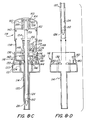
- FIGs 8A to 8D show the sequence of movement of the various elements of the safety trocar instrument as the cavity wall is penetrated and retraction of the trocar point is subsequently triggered.
- counterforce against the distal end of the trigger sleeve 120 is relieved when the trigger sleeve and cannula 114 clear the inner surface of the cavity wall so that the motion spring 148 may urge the trigger sleeve 120 downwardly again toward its rest position.
- This motion of the sleeve causes the radial flange 142 to pull the leg 176 downwardly thereby pivoting the pawl 168 so that it hook 172 is disengaged from the radial flange 154 on the trocar shaft.
- the trocar shaft 152 is thereby released so that its point 126 is once again retracted into the trigger sleeve 120 and cannula 114 by the force of the retractor spring 156, as depicted in Figure 8B.
- plunger head 140 When plunger head 140 is thereafter manually released, it may move upwardly within the main housing 138, under the influence of plunger spring 164, permitting the periphery 183 of the embracing ring 162 to clear the upper extreme of the housing 138 and again embrace the outer tapered sides 160 of pivotable pushers 158 to urge the pushers 158 together. The pushers may then again grip the proximal end 159 of the trocar shaft 152, as shown in Figure 8C. As can also be seen there, the leg 176 can swing about its pivot on the arm 174 so that the foot 178 can be disengaged from both the trigger-sleeve flange 142 and the head 182 of the tab 180. Appropriate biasing means for the latch can be provided to ensure disengagement.
- trigger sleeve-trocar subassembly may be removed from main body-cannula subassembly such that the cannula remains in the anatomical cavity wall to provide communication with the cavity interior.
- the present invention provides an improved safety trocar instrument that retracts a sharpened trocar point into a shielding trigger sleeve as soon as the distal end of the sleeve penetrates an anatomical cavity wall.
- the instrument may be self-contained and is mechanically actuated. Therefore, reliable operation does not depend on external power supplies or electrical triggering mechanisms.
Abstract
Description
- The present invention relates to a surgical instrument, commonly called a "trocar instrument" or "device," or simply a "trocar," that is used to pierce the wall of an anatomical cavity thereby forming a passageway providing communication with the inside of the cavity. Other medical instruments such as endoscopes, arthoscopes, and operating instruments can thereafter be inserted through the passageway to perform various medical procedures within the anatomical cavity.
- EP-A-O 479 130 discloses a safety trocar in which the cutting tip is withdrawn into the cannula in response to counter force being removed from the cutting tip. The counter force is removed from the cuffing tip when the tip enters a body cavity, and is sensed by springs. Accordingly, the sensing is remote from the distal end of the cannula and the tip and thus more susceptible to error through distance. It is desired to sense the counter force closer to the distal end of the cannula and lessen the chance for error.
- EP-A-O 499 457 discloses a safety trocar. After the trocar is advanced through a wall of a body cavity and reduces drag on the sleeve, the sleeve is automatically advanced distally. When the sleeve advances distally, the obturator retracts, thereby withdrawing the cutting tip into the cannula.
- EP-A-O 135 364 discloses a safety trocar in which a protective shield is biased after a piercing tip has passed through the wall of a body cavity. The protective shield is biased to cover blades and protect against any further puncturing.
- EP-A-O 511 676 discloses a safety trocar in which a piercing tip pierces a body wall and a distal end of a cannula is brought into contact with a body wall. The contact forces the cannula proximally until the cannula advances into the body cabity. Then, the absence of a counter force against the distal end of the cannula triggers a mechansim which automatically withdraws the tip into the cannula.
- Accordingly, none of the prior art cited shows a counter force sensing portion located between an extreme end of a trocar point and the distal end of a cannula which is desirable for the reasons above.
- Surgical techniques using trocar devices to pierce anatomical cavity walls have recently gained great favor in the expanding field known as "least invasive surgery." Such techniques have been widely employed, for example, in gall bladder surgery and their use for other types of operations is actively being explored and implemented. These methods are desirable because the passageway formed by the trocar is small and neat. Therefore, the major trauma associated with large surgical incisions, used to perform certain operations in the past, can be avoided.
- The present invention provides an improved safety trocar instrument that is well suited to least invasive surgical techniques. By its design the safety trocar instrument of the present invention not only avoids the trauma that results when large incisions are made in an anatomical cavity wall, but also reduces the chance that unintended and unwanted trauma will result particularly after the instrument penetrates the wall.
- In its elemental form, a trocar is a device comprising an elongated shaft of, for example, surgical steel having a sharpened blade or point. Typically, least invasive surgery using such a device is performed first by inserting a fine surgical or "Veress" needle through the cavity wall and thereafter injecting a fluid into the cavity to insufflate it and separate the cavity wall, including muscle and the peritoneum in the case of the abdomen, from other internal organs like the heart, stomach, and major blood vessels. The sharpened point of the trocar is then placed against the cavity wall and urged to pierce it by manually applying pressure to the proximal end of the shaft. An outer sleeve or "cannula" may be slid over the shaft through the wound created by the sharp point. The sleeve permits the shaft to be withdrawn from the cavity wall and maintains the passageway into the cavity. Observation and surgical instruments can then be introduced into the cavity through the sleeve.
- Safety trocars described in the prior art have certain inherent drawbacks. First, because the piercing tip of the trocar blade is generally shielded when the instrument is placed against the anatomical cavity wall, it is necessarily shielded from the surgeon's view. Therefore, the surgeon cannot be certain that the tip will puncture the wall at the precise location desired. Moreover, after the piercing tip has penetrated the cavity wall, it must protrude a further substantial distance into the anatomical cavity before the inner sleeve or shield is released again to cover the tip. Thus, a substantial period remains during which the tip is exposed and may injure internal organ structures. Since the inner sleeve or shield and outer sleeve may remain in the cavity after the trocar is removed, they often project a substantial distance into the cavity. Thus the available space in the cavity within which the surgeon can work is reduced.
- Therefore, still additional improvement to safety trocar instrument design would be greatly beneficial to the surgical community.
- It is a principal object of the present invention to provide an improved safety trocar instrument that mitigates the problems associated with prior art devices and has a safety shield that projects forwardly to surround a sharp trocar point after the point and distal end of the shield penetrate an anatomical cavity wall.
- It is an additional principal object of the present invention to provide a self-contained, mechanically actuated safety trocar instrument in which a sharp trocar point is retracted into a surrounding sleeve when the sharp point has penetrated an anatomical cavity wall. The invention thereby results in a substantial improvement over known prior art devices.
- These and other objects are achieved by the present invention, which includes a main body that supports an outer sleeve or cannula.
- In the first alternative embodiment, the main body is configured to mate with a trocar subassembly that includes a plunger head and a main housing having a trocar. The trocar has a sharp point.
- The safety trocar instrument in accordance with the first alternative this preferred embodiment is assembled by mating the main body-cannula subassembly with the trocar subassembly such that the trocar is received coaxially within the cannula. The trocar is urged by a retraction spring to a withdrawn rest position with the point surrounded by the distal end of the cannula.
- In the first alternative embodiment, the instrument is armed to pierce an anatomical cavity wall by manually pressing the plunger head of the trocar subassembly into the main body until the sharp trocar point projects beyond the distal end of the cannula with the trocar in a fully extended position. The trocar is initially held in such attitude by an internal latching mechanism residing in the plunger head and main housing of the trocar subassembly. However, the trocar is linked to the latching mechanism through a lost-motion coupling that permits it to be urged backwardly into the housing and plunger head, to an intermediate retracted position, against the force of a pressure spring. The point is nevertheless exposed when the trocar is in the intermediate position.
- Once armed, the trocar of the first alternative embodiment is used to pierce an anatomical cavity wall by pressing the exposed point of the trocar against the wall at precisely the desired location. During this operation, pressure against the trocar point urges the trocar backwardly through the lost-motion coupling to the intermediate position in a first stage to prepare a trip mechanism for disarming the latching mechanism. When the cavity wall has been completely penetrated, pressure on the trocar point is relieved permitting it again to be returned through the lost-motion coupling by the pressure spring to its fully extended position. The return of the trocar point causes the trip mechanism to fully disarm the latch mechanism thereby releasing the trocar and permitting it to be retracted to its rest position by the retractor spring with its sharp point surrounded by the distal end of the cannula. The trocar subassembly can then be removed leaving the cannula in the anatomical cavity wall to provide communication with the inside of the cavity.
- In the second alternative embodiment, the main body is configured to mate with a trigger sleeve and trocar subassembly that includes a main housing and a plunger head in which a trigger sleeve is axially reciprocally mounted. The trigger sleeve is urged to a rest position projecting outwardly from the main housing. A trocar having a sharp point is coaxially received within the trigger sleeve for reciprocal movement and is urged to a retracted rest position with the sharp point surrounded by the distal end of the sleeve.
- The safety trocar instrument in accordance with the second alternative embodiment is assembled by mating the main body-cannula subassembly with the trigger sleeve-trocar subassembly with the inner sleeve and trocar received coaxially within the cannula.
- The second alternative embodiment, the instrument is armed to pierce an anatomical cavity wall by manually pressing the plunger head of the trigger sleeve-trocar subassembly into the main body until the distal end of the trigger sleeve projects slightly beyond the distal end of the cannula and thereafter the sharp trocar point projects beyond the distal end of the trigger sleeve. The trocar is latched in such attitude by an internal latching mechanism residing in the plunger head and main housing of the trigger sleeve-trocar subassembly, but the trigger sleeve remains free to reciprocate by being urged back into the cannula. The trocar instrument is then used to pierce an anatomical cavity wall by pressing the exposed point of the trocar against the wall at precisely the desired location. After the point begins to penetrate the wall, the distal end of the trigger sleeve encounters the outer surface of the wall. The resistance of the wall thereafter causes the trigger sleeve to be urged inwardly into the cannula to a retracted position in a first stage preparatory to disarming the latching mechanism. When the cavity wall has been completely penetrated pressure on the trigger sleeve is relieved permitting it again to be urged back to its rest position. The return of the trigger sleeve then fully disarms the latch mechanism thereby releasing the trocar shaft and permitting it to be retracted to its rest position with its sharp point surrounded by the trigger sleeve and cannula. The trocar shaft and trigger subassembly can then be removed leaving the cannula in the anatomical cavity wall to provide communication with the inside of the cavity.
- Thus the present invention provides a safety trocar instrument in which the sharp point of the trocar is retracted into a surrounding shield structure. Since retraction occurs immediately upon entry of the trocar point into the anatomical cavity, there is a reduced likelihood of injury to internal organs. Moreover, since retraction occurs promptly at that time, little of the device remains in the cavity after penetration to infringe upon the surgeon's work area. Still further, the trocar point is exposed to the surgeon's view at the start of penetration so that the surgeon can precisely position it at the desired cavity wall location. Thus the safety trocar instrument of the present invention is a substantial improvement over designs of the type disclosed in the prior art.
- The present invention is also entirely self-contained and mechanically actuated. Therefore, it is not affected by electrical power failures or interruptions nor does it depend on cumbersome ancillary electrical equipment. And since no wire connections to such ancillary equipment are required, they are not present to interfere with the surgeon's work.
- These and other objects, aspects, features, and advantages of the present invention will become apparent from the following detailed description taken in conjunction with the accompanying drawings.
-
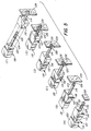
- Figures 1A to 1F are a sequence of perspective views of the preferred embodiment of the safety trocar instrument of the present invention showing it at various stages during use;
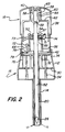
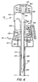
- Figure 2 is a vertical cross-sectional view of the safety trocar instrument of the present invention shown in its assembled rest condition;
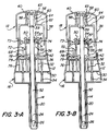
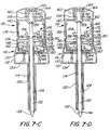
- Figures 3A to 3D are a sequence of vertical cross-sectional views of the safety trocar instrument of the present invention showing it being armed and operated through initial piercing of an anatomical cavity wall; and
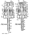
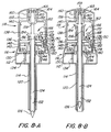
- Figures 4A to 4D are a sequence of vertical cross-sectional views of the safety trocar instrument of the present invention showing the trocar retraction operation and the trocar subassembly being removed from the main body-cannula assembly.
-
- Figures 1A though 1F diagrammatically show the safety trocar instrument in accordance with first alternative embodiment of the present invention as it appears in various stages of use. More particularly, this safety trocar instrument, generally indicated at 10, includes a
main body 12 having an outer tubular sleeve orcannula 14 projecting from it. The main body-cannula subassembly, generally indicated at 16, is configured to mate with a trocar subassembly generally indicated at 18, that includes asleeve 20, mounted in ahousing 22, and anelongate trocar 24, having asharp point 26 and being mounted for axial reciprocal movement in thesleeve 20 but being urged to a retracted position therein. - In the assembled rest position of the
instrument 10 shown in Figure 1A, in which thesleeve 20 andcannula 14 are partly broken away to show the location of thetrocar point 26, thetrocar subassembly 18 is mated with the main body-cannula subassembly 16 such that the coaxially arrangedtrocar 24 andsleeve 20 are in turn received coaxially within thecannula 14. As can be seen, in this rest position the distal end of the sleeve resides entirely within the distal end of the cannula and thesharp point 26 of the trocar resides within the distal end of thesleeve 20. Thus, in the rest position the sleeve andcannula 14 shield thetrocar point 26. - The assembled instrument is armed, as shown in Figure 1B, to pierce an
anatomical wall 28 by manually squeezing thetrocar subassembly 18 into the main body-cannula subassembly 16. This operation causes thesharp trocar point 26 to project beyond the distal ends of both thesleeve 20 andcannula 14. The trocar is latched in this fully extended position by an internal latching mechanism but is permitted partially to retract from the fully extended position by a lost-motion coupling. Both the latching mechanism and lost-motion coupling will be described in detail below. Thus the trocar point is exposed in preparation for puncturing thecavity wall 28. - As shown in Figures 1B and 1C, the
trocar point 26 is visible to a surgeon so that it can be precisely positioned at the desired location on ananatomical cavity wall 28 for the intended puncture wound. As the point begins penetration, counterforce exerted by thewall 28 urges thetrocar 24 back toward, but not withdrawn into, the distal end of the cannula to an intermediate retracted position as permitted by the lost-motion coupling. In this intermediate position, a trip mechanism is prepared to disarm the internal latching mechanism. - Figure 1D shows the state of the
trocar instrument 10 in which both thetrocar point 26 and the distal ends of thesleeve 20 andcannula 14 have cleared the inside surface of thewall 28. Accordingly, the counterforce exerted by the wall on the trocar is relieved permitting it again to be projected to its fully extending position. This action causes the trip mechanism to disarm the internal latch mechanism permitting the trocar to be retracted to its rest position with thetrocar point 26 shielded within thesleeve 20 andcannula 14 distal ends, as shown in Figure 1E. In Figure 1E thesleeve 20 andcannula 14 are shown partly broken away for clarity as in Figure 1A. - Finally, as shown in Figure 1F, the
trocar subassembly 18 can be withdrawn from the main body-cannula subassembly 16 with thecannula 14 remaining in the puncture wound in thewall 28. The cannula thus provides a passage through the cavity wall into the cavity interior. - The specific structure of the
safety trocar instrument 10 in accordance with a preferred embodiment of the present invention will now be described with reference to Figure 2, which is a vertical cross-sectional view thereof. The trocar device includes themain body 12 having thecannula 14 extending therefrom. Themain body 12 is formed with anintermediate partition 30, an upwardly projectingstop 32 on thepartition 30, and a capturedcompression spring 34. Themain body 12 is also formed with a generally rectangularly shapedsocket 36 projecting upwardly from thepartition 30. - The
trocar subassembly 18 is configured to mate with main body-cannula subassembly 16 and includes amain housing 38 having an integrally formedplunger head 40, and thesleeve 20, which has aradial flange 42 at its proximal end and is mounted for reciprocal movement within thehousing 38. The bottom of themain housing 38 is rectangularly shaped to be telescopically received in thesocket 36. - The
trocar 24 is mounted for axial reciprocal movement within the trocar subassembly and includes ashaft 52 having radially projecting upper andlower flanges sharp point 26 at its distal end. Thetrocar shaft 52 is coaxially received within thesleeve 20. Astop plate 50 is received about thetrocar shaft 52 between the upper andlower flanges radial flange 54 by apressure spring 57. Thestop plate 50,pressure spring 57, andflanges - The
trocar 24 is urged to a retracted rest position by aretractor spring 56 compressed between the lower side of thestop plate 50, which engages theupper flange 54, and thesleeve flange 42. Thetrocar 24 is also stopped in this retracted rest position by a pair ofpivotable pushers 58 mounted in theplunger head 40 that, when closed in the radial direction, engage theproximal end 59 of thetrocar shaft 52, which has a reduced diameter. Thepivotable pushers 58 each have a downwardly, radially outwardly taperedouter cam surface 60 that is engaged by an inner aperture in an embracingring 62 mounted in theplunger head 40. Thering 62 is urged downwardly by aplunger spring 64 that is compressed between it and the inner surface of the top 65 of theplunger head 40. The embracingring 62, which thus constitutes a cam driver, urges thepivotable pushers 58 radially together by engaging the tapered outer pusher surfaces 60. - In addition, the trocar subassembly incorporates a latch mechanism the function of which was generally described above. Now, in detail, this latch mechanism includes latch means 66 in the form of a
pawl 68 mounted for pivoted movement on thesleeve flange 42, and anupstanding tab 76 projecting upwardly from theintermediate partition 30 in the main body through a hole in the bottom of the main housing. Thepawl 68 is formed with ahook 72 at its upper end, which can override and engage an upper edge of thestop plate 50, and afoot 78 at its lower end that can engage acatch 79 at the upper end of thetab 76. - A trip mechanism 75 for the latch mechanism, comprising the
tab 76 andpawl 68, includes anarm 74 pivotably mounted in the plunger head. Thearm 74 has atab 71, which can be engaged by the lower edge of thelower flange 55 to cause thearm 74 to pivot in the counterclockwise direction, and afinger 73, which can engage thefoot 78 ofpawl 68. It is these latch and trip mechanisms, in cooperation with thetrocar flanges stop plate 50, that determine the sequence of operations of the trocar instrument described above with reference to Figures 1A to 1F. - More particularly, Figures 3A through 3D show the sequence of movements of the various elements of the safety trocar instrument described above from the rest position to arming of the instrument, and, in turn, to initial penetration of the anatomical cavity wall.
- In the initial rest position shown in Figure 3A, which is substantially the same as Figure 2, the
trocar subassembly 18 is inserted into the main body-cannula subassembly 16 with thesleeve 20 andtrocar shaft 52 coaxially received within thecannula 14. The distal ends of thesleeve 20 andcannula 14 terminate at nearly the same axial location, with themain housing 38 being urged outwardly from themain body 12 to its rest position by therelaxed compression spring 34. - When the device is to be used, the
trocar subassembly 18 is manually squeezed into main body-cannula subassembly 16 thereby compressing the capturedspring 34, until thecatch 79 of thetab 76 catches thefoot 78 of thepawl 68 with thesleeve flange 42 abutting thestop 32, which projects through holes in the bottom of themain housing 38. At this stage, the trocar shaft is moved downwardly a small distance by thepushers 58, but thetrocar point 26 remains within both thesleeve 20 andcannula 14, as shown in Figure 3B. - Further depression of
plunger head 40 relative to themain housing 38 causes thepivotable pushers 58 to push thetrocar shaft 54 axially downwardly further until thehook 72 of thepawl 68 overrides and catches the edge of thestop plate 50 thereby compressing theretractor spring 56. At this stage thetrocar point 26 projects to a fully extended position beyond the distal ends of both thesleeve 20 andcannula 14, as shown in Figure 3C. Those distal ends also become substantially coextensive. - Ultimately, complete depression of
plunger head 40 causes the sidewall of the embracingring 62 to engage the periphery of thesleeve flange 42, which as noted has come to rest on the top of astop 32 projecting upwardly from theintermediate partition 30. Therefore, further downward movement of theplunger head 40 causes the embracingring 62 to move upwardly relative to thepushers 58, which are then permitted to spread radially outwardly and release theproximal end 59 of thetrocar shaft 52. In this configuration, shown in Figure 3C, the trocar instrument is armed and ready to pierce an anatomical cavity wall. - The instrument can then create a puncture wound by pressing the
point 26 of thetrocar 24 against the cavity wall. As the point begins its entry, resistance or counterforce exerted by the wall causes thelower portion 98 oftrocar shaft 52 to be urged inwardly intocannula 14 andsleeve 20, against the force of thepressure spring 57, to an intermediate retracted position until the edge of thelower flange 55 overrides thetab 71 ofarm 74, as shown in Figure 3D. The upper andlower flanges pressure spring 57 permit this lost trocar motion 96 relative to thestop plate 50. - Figures 4A to 4D show the sequence of movement of the various elements of the safety trocar instrument as the cavity wall is penetrated and retraction of the
trocar point 26 is subsequently triggered. As depicted in Figure 4A, counterforce against thepoint 26 of thetrocar shaft 52 is relieved when the trocar andcannula 14 clear the inner surface of the cavity wall. Therefore, thepressure spring 57 may urge thetrocar shaft 52 downwardly again from the intermediate position toward the fully extended position. This motion of the trocar causes thearm 74 to be pivoted in the counterclockwise direction by engagement of the edge of thelower flange 55 with thetab 71. The extreme end of thearm 74 then depresses thefoot 78 ofpawl 68 causing it also to pivot in the counterclockwise direction to disengage itshook 72 from the edge of thestop plate 50, thereby releasing thestop plate 50. Theretractor spring 56 compressed between theflange 42 and thestop plate 50 then urges thetrocar shaft 52 upwardly into thesleeve 20 andcannula 14 to its withdrawn rest position with the point shielded within the distal ends of both, as depicted in Figure 4B. - When the
plunger head 40 is thereafter manually released, it may move upwardly within themain housing 38 under the influence ofcompressed spring 34, disengaging the sidewall of the embracingring 62 from the periphery of thesleeve flange 42. Thering 62 may then be urged downwardly to embrace thepushers 58 and urge them together. The pushers may then again grip theproximal end 59 of thetrocar shaft 52, as shown in Figure 4C. As can also be seen there, thepawl 68 can swing about its pivot so that thefoot 78 can be disengaged from thecatch 79 of theleg 76. - Thereafter the trocar subassembly may be removed from the main body-cannula subassembly such that the cannula remains in the anatomical cavity wall to provide communication with the cavity interior.
- It should be noted that the
sleeve 20 in the trocar subassembly is long enough in the preferred embodiment to shield the trocar point, particularly when the trocar subassembly is in its rest condition and removed from the main body-cannula subassembly. However, thesleeve 20 may be eliminated if desired since it, by itself, is not necessary to retraction of the trocar point into the distal end of the cannula. If the sleeve is eliminated, the cannula will shield the trocar point after it is retracted following cavity penetration. -
- Figures 5A to 5F are a sequence of perspective views of the preferred embodiment of the safety trocar instrument of the present invention showing it at various stages during use;
- Figure 6 is a vertical cross-sectional view of the safety trocar instrument of the present invention shown in its assembled rest condition;
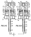
- Figures 7A to 7D are a sequence of vertical cross-sectional views of the safety trocar instrument of the present invention showing it being armed and operated through initial piercing of an anatomical cavity wall; and
- Figures 8A to 8D are a sequence of vertical cross-sectional views of the safety trocar instrument of the present invention showing the trocar retraction operation and the trigger sleeve-trocar subassembly being removed from the main body-cannula assembly.
-
- Figures 5A though 5F diagrammatically show the safety trocar instrument in accordance with the second alternative embodiment of the present invention as it appears in various stages of use. More particularly, this safety trocar instrument, generally indicated at 110, includes a
main body 112 having an outer tubular sleeve orcannula 114 projecting from it. The main body-cannula subassembly, generally indicated at 116, is configured to mate with a trigger sleeve-trocar subassembly generally indicated at 118, that includes atubular trigger sleeve 120, mounted for reciprocal movement in a housing 122 and urged to an outwardly extending position therefrom, and anelongate trocar 124, having asharp point 126 and being mounted for axial reciprocal movement in thetrigger sleeve 120 but being urged to a retracted position therein. - In the assembled rest position of the
instrument 110 shown in Figure 5A, in which thetrigger sleeve 120 andcannula 114 are partly broken away to show the location of thetrocar point 126, the trigger sleeve-trocar subassembly 118 is mated with the main body-cannula subassembly 116 such that the coaxially arranged trocar 122 and triggersleeve 120 are in turn received coaxially within thecannula 114. As can be seen, in this rest position the distal end of the trigger sleeve resides substantially entirely within the distal end of the cannula and thesharp point 126 of the trocar resides within the distal end of thetrigger sleeve 120. Thus, in the rest position the trigger sleeve shields thetrocar point 126. - The assembled instrument is armed, as shown in Figure 5B, to pierce an
anatomical wall 128 by manually squeezing the trigger sleeve-trocar subassembly 118 into the main body-cannula subassembly 116. This operation causes the distal end of thetrigger sleeve 120 to project beyond the distal end of thecannula 114 and causes thesharp trocar point 126 to project beyond the distal end of thetrigger sleeve 120. The trocar is latched in this projecting position by an internal latching mechanism to be described in detail below. Thus the trocar point is exposed in preparation for puncturing thecavity wall 128. - As shown in Figures 5B and 5C, the
trocar point 126 is visible to a surgeon so that it can be precisely positioned at the desired location on ananatomical cavity wall 128 for the intended puncture wound. As the point begins penetration, counterforce exerted by thewall 128 urges the distal end of thetrigger sleeve 120 back into the distal end of the cannula to a first position. In this first retracted position, the trigger sleeve is prepared to disarm the internal latch mechanism holding the trocar in its extended position. - Figure 5D shows the state of the
trocar instrument 110 in which both the trocar point and the distal ends of the trigger sleeve and cannula have cleared the inside surface of thewall 128. Accordingly, the counterforce exerted by the wall on the trigger sleeve is relieved permitting it again to be projected to its extended position with its distal end protruding beyond the distal end of the cannula. This action of the trigger sleeve disarms the internal latch mechanism permitting the trocar to be retracted to its rest position with the trocar point within the trigger sleeve distal end, as shown in Figure 5E. In Figure 5E the trigger sleeve and cannula are shown partly broken away for clarity as in Figure 5A. - Finally, as shown in Figure 5F, the trigger sleeve-
trocar subassembly 118 can be withdrawn from the main body-cannula subassembly 116 with thecannula 114 remaining in the puncture wound in thewall 128. The cannula thus provides a passage through the cavity wall into the cavity interior. - The specific structure of the
safety trocar instrument 110 in accordance with a preferred embodiment of the present invention will now be described with reference to Figure 6, which is a vertical cross-sectional view thereof. The trocar device includes themain body 112 having thecannula 114 extending therefrom. Themain body 112 is formed with anintermediate partition 130, an upwardly projectingstop 132 on thepartition 130, and a capturedcompression spring 134. Themain body 112 is also formed with a generally rectangularly shapedsocket 136 projecting upwardly from thepartition 130. - The trigger sleeve-
trocar subassembly 118 is configured to mate with main body-cannula subassembly 116 and has amain housing 138, aplunger head 140, and thetrigger sleeve 120, which is reciprocally mounted withinhousing 138. The bottom of themain housing 138 is rectangularly shaped to be telescopically received in thesocket 136. Theplunger head 140 is mounted for reciprocal telescoping movement relative to thehousing 138 and the two elements are prevented from disengaging from one another by suitable means (not shown). - The
trigger sleeve 120 has a rest position relative to themain housing 138 in which aradial flange 142 at its proximal end is supported by aretainer 144 on thebottom 146 of thehousing 138. The trigger sleeve is urged to this rest position by amotion spring 148 compressed between the radialtrigger sleeve flange 142 and the underside of an innerhorizontal partition 150 formed withinhousing 138. - The
trocar 124 is also mounted for axial reciprocal movement within the trigger sleeve-trocar subassembly and includes ashaft 152 having catch means in the form of aradial flange 154 near its proximal end and thesharp point 126 at its distal end. Thetrocar shaft 152 is coaxially received within thetrigger sleeve 120. Thetrocar 124 is urged to a retracted rest position by aretractor spring 156 compressed between the upper side of thehorizontal partition 150 and theradial flange 154. Thetrocar 124 is also stopped in this retracted rest position by a pair ofpivotable pushers 158 mounted in theplunger head 110 that, when closed in the radial direction, engage theproximal end 159 of thetrocar shaft 152, which has a reduced diameter. Thepivotable pushers 158 each have a downwardly, radially outwardly taperedouter cam surface 160 that is engaged by an inner aperture in an embracingring 162 mounted in theplunger head 140. Thering 162 is urged downwardly by aplunger spring 164 that is compressed between it and the inner surface of the top 165 of theplunger head 140. The embracingring 162, which thus constitutes a cam driver, urges thepivotable pushers 158 radially together by engaging the tapered outer pusher surfaces. - In addition, the trigger sleeve-trocar subassembly incorporates a latch mechanism, indicated generally at 166, the function of which was generally described above. Now, in detail, this
latch mechanism 166 includes latch means in the form of apawl 168 mounted for pivoted movement on astand 170 projecting upwardly from theinner partition 150 within thehousing 138. Thepawl 168 is formed with ahook 172 that can engage the top of theflange 154 on thetrocar shaft 152. Asidewardly projecting arm 174 is formed on thepawl 168 and carries pivotably mounted trip means 175 in the form of aleg 176 that projects downwardly through thepartition 150 and has anenlarged foot 178 at its lower free end. This foot is configured to engage thehead 182 of anupstanding tab 180 projecting from thepartition 130 in the main body through a hole in thebottom 146 of thehousing 138. It is this latch mechanism, in cooperation with thetrocar flange 154 and thetrigger sleeve flange 142, that determines the sequence of operations of the trocar instrument described above with reference to Figures 5A to 5F. - More particularly, Figures 7A through 7D show the sequence of movements of the various elements of the safety trocar instrument described above from the rest position to arming of the instrument, and, in turn, to initial penetration of the anatomical cavity wall.
- In the initial rest position shown in Figure 7A, which is substantially the same as Figure 6, the trigger sleeve-
trocar assembly 118 is inserted into the main body-cannula subassembly 116 with thetrigger sleeve 120 andtrocar shaft 52 coaxially received within thecannula 114. The distal ends oftrigger sleeve 120 andcannula 114 terminate at about the same axial location, with themain housing 138 being urged outwardly from themain body 112 to its rest position by therelaxed compression spring 134. - When the device is to be used, the trigger sleeve-
trocar subassembly 118 is manually squeezed into main body-cannula subassembly 116 thereby compressing the capturedspring 134, until thebottom wall 146 ofhousing 138 abuts thestop 132. In this position, shown in Figure 7B, thefoot 178 of theleg 176 is caught under thehead 182 of thetab 180. The distal end of thetrigger sleeve 120 projects slightly beyond on the distal end of thecannula 114, but thepoint 126 of thetrocar 124 remains within bothtrigger sleeve 120 andcannula 114. - Further depression of
plunger head 140 relative to themain housing 138 causes thepivotable pushers 158 to push thetrocar shaft 154 axially downwardly until thehook 172 of thepawl 168 overrides theflange 154 on theshaft 152. Thepoint 126 of thetrocar 124 then projects beyond the distal ends of both thetrigger sleeve 120 andcannula 114, as shown in Figure 7C. - Ultimately, complete depression of
plunger head 140 causes the periphery 183 of the embracingring 162 to engage the upper extreme 184 of thehousing 138 thereby stopping relative embracing ring-main housing movement. Further downward movement of theplunger head 140 causes the embracingring 162 to move upwardly relative to thepushers 158 which are then permitted to spread radially outwardly and release theproximal end 159 of thetrocar shaft 152. In this configuration, shown in Figure 7C, the trocar instrument is armed and ready to pierce an anatomical cavity wall. - The instrument can then create a puncture wound by pressing the
point 126 of thetrocar 124 against the cavity wall. After the point begins its entry, the distal end of the trigger sleeve encounters the cavity wall. Resistance or counterforce exerted by the wall causes thetrigger sleeve 120 to be urged inwardly intocannula 114, against the force of themotion spring 148, until the edge of the radialtrigger sleeve flange 142 overrides thefoot 178 of theleg 176, as shown in Figure 7D. - Figures 8A to 8D show the sequence of movement of the various elements of the safety trocar instrument as the cavity wall is penetrated and retraction of the trocar point is subsequently triggered. As depicted in Figure 8A, counterforce against the distal end of the
trigger sleeve 120 is relieved when the trigger sleeve andcannula 114 clear the inner surface of the cavity wall so that themotion spring 148 may urge thetrigger sleeve 120 downwardly again toward its rest position. This motion of the sleeve causes theradial flange 142 to pull theleg 176 downwardly thereby pivoting thepawl 168 so that it hook 172 is disengaged from theradial flange 154 on the trocar shaft. - The
trocar shaft 152 is thereby released so that itspoint 126 is once again retracted into thetrigger sleeve 120 andcannula 114 by the force of theretractor spring 156, as depicted in Figure 8B. - When
plunger head 140 is thereafter manually released, it may move upwardly within themain housing 138, under the influence ofplunger spring 164, permitting the periphery 183 of the embracingring 162 to clear the upper extreme of thehousing 138 and again embrace the outertapered sides 160 ofpivotable pushers 158 to urge thepushers 158 together. The pushers may then again grip theproximal end 159 of thetrocar shaft 152, as shown in Figure 8C. As can also be seen there, theleg 176 can swing about its pivot on thearm 174 so that thefoot 178 can be disengaged from both the trigger-sleeve flange 142 and thehead 182 of thetab 180. Appropriate biasing means for the latch can be provided to ensure disengagement. - Thereafter the trigger sleeve-trocar subassembly may be removed from main body-cannula subassembly such that the cannula remains in the anatomical cavity wall to provide communication with the cavity interior.
- Accordingly, it will be appreciated that the present invention provides an improved safety trocar instrument that retracts a sharpened trocar point into a shielding trigger sleeve as soon as the distal end of the sleeve penetrates an anatomical cavity wall. The instrument may be self-contained and is mechanically actuated. Therefore, reliable operation does not depend on external power supplies or electrical triggering mechanisms.
- Although specific embodiments of the present invention have been described above in detail, it will be understood that this description is merely for purposes of illustration. Various modifications of and equivalent structures corresponding to the disclosed aspects of the preferred embodiments in addition to those described above may be made by those skilled in the art without departing from the spirit of the present invention which is defined in the following claims, the scope of which is to be accorded the broadest interpretation so as to encompass such modifications and equivalent structures.
Claims (8)
- A safety trocar instrument for piercing a wall of an anatomical cavity, having an interior, to provide communication with the interior of the cavity, said trocar instrument comprising:(a) a tubular cannula (14, 114) having a distal end (15, 115);(b) an elongate trocar (24, 124), having a sharp piercing point (26, 126) terminating in an extreme end, reversibly shielded by a sleeve (20, 120) having a distal end (17, 117) mountable for axial reciprocal movement within said cannula (14, 114) between a withdrawn rest position in which said point is received within and shielded by the distal end (15, 115) of said cannula (14, 114) and sleeve (20, 120) and a projecting position in which said point (26, 126) is exposed beyond the distal end (15, 115) of said cannula (14, 114) and sleeve (20, 120);(c) means for biasing (56, 156) said trocar (24, 124) to its withdrawn rest position;(d) latch means (66, 166) for latching said trocar (24, 124) in the projecting position in opposition to said biasing means (56, 156) to allow clear unobstructed visibility of the wall of the cavity for precision-piercing thereof;(e) trip means (75, 175) for tripping said latching means (66, 166) to unlatch said trocar (24, 124) and thereby permitting said trocar (24, 124) to be moved to its withdrawn rest position by said biasing means (56, 156);(f) mechanical trigger means (57, 55 and 71) mounted within said instrument (10, 110), having a counterforce sensing portion (98, 198) locatable between the extreme end of said trocar point (26, 126) and the distal end (15, 115) of said cannula (14, 114), said sensing portion (98, 198) sensing a counterforce exerted by the wall of the cavity after it has begun to be pierced by said trocar point (26, 126) and sensing relief of such counterforce when said sensing portion (98, 198) has pierced the wall of the cavity, said trigger means (96) being mechanically coupleable to said trip means (75, 175) to cause said trip means (75, 175) to trip said latch means (66, 166) in response to sensing relief of such counter force to protect internal organs; and(g) plunger means for manually moving said trocar (24, 124) from the withdrawn rest position to the projecting position;
wherein said trigger means comprises a tubular trigger sleeve (20, 120) in which said trocar (24, 124) is coaxially received, and said sensing portion comprises the distal end (17, 117) of said trigger sleeve (20, 120) which is locatable between the extreme of said trocar point (26, 126) and the distal end (15, 115) of said cannula (14, 114), said trigger sleeve (20, 120) being mounted coaxially within said cannula (14, 114) for reciprocal movement between an extended rest position with the trigger sleeve (20, 120) distal end (17, 117) located between the extreme of said trocar point (26, 126) and the distal end (15, 115) of said cannula (14, 114) and a retracted position with the trigger sleeve (20, 120) distal end (17, 117) retracted toward the distal end (15, 115) of said cannula (14, 114). - The safety trocar instrument (10, 110) according to Claim 1, wherein said trigger sleeve (20, 120) is mounted to be coupled to said trip means (75, 175) when it is moved to the retracted position and thereafter causes said trip means (75, 175) to trip said latch means (66, 166) when it is returned to its extended rest position.
- The safety trocar instrument (10, 110) according to Claim 2, further comprising means (56, 156) for urging said trigger sleeve (20, 120) to its extended rest position.
- The safety trocar instrument (10, 110) according to Claim 1, wherein said trigger means (57, 55 and 71) is comprised of said elongate trocar (24, 124), said trocar being mounted for axial reciprocal movement with said cannula (14, 114) between the withdrawn rest position, the fully extended projecting position, and an intermediate position retracted toward the rest position from the fully extended position in which said point (26, 126) is also exposed beyond the distal end (15, 115) of said cannula (14, 114);
and wherein said trip means (75, 175) couples said trocar (24, 124) to said latch means (66, 166) when said trocar (24, 124) moves from the fully extended position to the intermediate position, and trips said latch means (66, 166) when said trocar (24, 124) returns toward said fully extended position to unlatch said trocar (24, 124) and thereby permit said trocar (24, 124) to be moved to the withdrawn rest position by said biasing means (56, 156). - The safety trocar instrument (10, 110) according to Claim 4, further comprising means for urging said trocar (24, 124) from the intermediate position toward the fully extended position when said trocar (24, 124) is latched to said latch means (66, 166).
- The safety trocar instrument (10, 110) according to Claim 4, wherein said trocar (24, 124) further comprises lost-motion coupling means (98, 198) for coupling said trocar (24, 124) to said latch means (66, 166) and including upper and lower flanges mounted in the region of the proximal end of said trocar (24, 124) and a stop plate mounted on said trocar (24, 124) for reciprocal movement between said upper and lower flanges.
- The safety trocar instrument (10, 110) according to Claim 1, wherein said plunger means comprises means for gripping a portion of said trocar (24, 124) remote from said piercing point (26, 126) when said trocar (24, 124) is in the withdrawn rest position and for releasing said remote portion when said trocar (24, 124) reaches the fully extended position.
- The safety trocar instrument (10, 110) according to Claim 1, wherein said trocar (24, 124), said biasing means (56, 156), and said trip means (75, 175) constitute a trocar subassembly (18, 118) that is removable as a unit from said cannula (14, 114).
Applications Claiming Priority (2)
| Application Number | Priority Date | Filing Date | Title |
|---|---|---|---|
| US07/787,183 US5158552A (en) | 1991-11-04 | 1991-11-04 | Safety trocar instrument having a retractable trocar actuated by relief of pressure on the trocar point |
| US787183 | 1991-11-04 |
Publications (2)
| Publication Number | Publication Date |
|---|---|
| EP0540887A1 EP0540887A1 (en) | 1993-05-12 |
| EP0540887B1 true EP0540887B1 (en) | 2000-08-09 |
Family
ID=25140659
Family Applications (1)
| Application Number | Title | Priority Date | Filing Date |
|---|---|---|---|
| EP92117089A Expired - Lifetime EP0540887B1 (en) | 1991-11-04 | 1992-10-07 | Safety trocar |
Country Status (13)
| Country | Link |
|---|---|
| US (1) | US5158552A (en) |
| EP (1) | EP0540887B1 (en) |
| JP (1) | JPH05208022A (en) |
| KR (1) | KR930009572A (en) |
| AT (1) | ATE195237T1 (en) |
| AU (1) | AU653866B2 (en) |
| CA (1) | CA2081927C (en) |
| DE (1) | DE69231330T2 (en) |
| ES (1) | ES2149766T3 (en) |
| MX (1) | MX9206277A (en) |
| PL (1) | PL296455A1 (en) |
| TW (1) | TW235910B (en) |
| ZA (1) | ZA928477B (en) |
Families Citing this family (75)
| Publication number | Priority date | Publication date | Assignee | Title |
|---|---|---|---|---|
| DE479130T1 (en) * | 1990-10-05 | 1993-11-25 | United States Surgical Corp | Security trocar. |
| US5827315A (en) * | 1994-01-04 | 1998-10-27 | Yoon; Inbae | Safety penetrating instrument with penetrating member protected after penetration to predetermined depth |
| US5645556A (en) * | 1990-12-18 | 1997-07-08 | Yoon; Inbae | Safety penetrating instrument with triggered penetrating member retraction and single or multiple safety member protrusion |
| US5466224A (en) * | 1990-12-18 | 1995-11-14 | Yoon; Inbae | Safety penetrating instrument having a triggered portal sleeve for establishing an endoscopic portal in an anatomical cavity wall |
| US5645557A (en) * | 1990-12-18 | 1997-07-08 | Yoon; Inbae | Safety penetrating instrument with triggered penetrating member retraction and safety member protrusion |
| US5431635A (en) * | 1990-12-18 | 1995-07-11 | Yoon; Inbae | Safety penetrating instrument having a triggered safety member for establishing an endoscopic portal in an anatomical cavity wall |
| US5578053A (en) * | 1993-06-24 | 1996-11-26 | Yoon; Inbae | Safety needle instrument having a triggered safety member |
| US5474539A (en) * | 1991-02-07 | 1995-12-12 | Origin Medsystems, Inc. | Trocar with retracting tip |
| US5152754A (en) * | 1991-02-15 | 1992-10-06 | Minnesota Mining And Manufacturing Company | Trocar |
| US5295993A (en) * | 1991-04-30 | 1994-03-22 | United States Surgical Corporation | Safety trocar |
| US5360405A (en) * | 1991-11-27 | 1994-11-01 | Inbae Yoon | Automatic retractable safety penetrating instrument |
| US5445617A (en) * | 1991-11-27 | 1995-08-29 | Yoon; Inbae | Automatic retractable safety penetrating instrument for portal sleeve introduction and method of use |
| US5320610A (en) * | 1991-12-16 | 1994-06-14 | Inbae Yoon | Automatic retractable trocar with safety shield and method of use |
| US5330432A (en) * | 1991-12-06 | 1994-07-19 | Inbae Yoon | Retractable safety penetrating instrument |
| US5324268A (en) * | 1991-12-16 | 1994-06-28 | Inbae Yoon | Trocar with safety shield |
| US5645076A (en) * | 1991-08-14 | 1997-07-08 | Yoon; Inbae | Automatic retractable safety penetrating instrument |
| US5207647A (en) * | 1991-11-05 | 1993-05-04 | Phelps David Y | Needle device |
| US5665072A (en) * | 1991-11-27 | 1997-09-09 | Yoon; Inbae | Safety needle instrument with movable cannula and needle |
| US5713870A (en) * | 1991-11-27 | 1998-02-03 | Yoon; Inbae | Retractable safety penetrating instrument with laterally extendable spring strip |
| WO1993010836A1 (en) * | 1991-11-27 | 1993-06-10 | Inbae Yoon | Retractable safety penetrating instrument for portal sleeve introduction |
| US5573511A (en) * | 1991-11-27 | 1996-11-12 | Yoon; Inbae | Retractable safety penetrating instrument with safety probe |
| US5779680A (en) * | 1991-11-27 | 1998-07-14 | Yoon; Inbae | Retractable safety needle instrument with movable safety member |
| US5603719A (en) * | 1991-11-27 | 1997-02-18 | Yoon; Inbae | Retractable safety trocar with multiple triggering and/or moving components |
| US5584849A (en) * | 1991-11-27 | 1996-12-17 | Yoon; Inbae | Retractable safety penetrating instrument with safety shield and multiple triggering and/or moving components |
| AU651745B2 (en) * | 1991-12-13 | 1994-07-28 | Covidien Ag | Locking pneumoneedle |
| US5441513A (en) * | 1992-03-12 | 1995-08-15 | United States Surgical Corporation | Retracting tip trocar assembly |
| US5226891A (en) * | 1992-04-07 | 1993-07-13 | Applied Medical Resources | Seal protection apparatus |
| US5707362A (en) * | 1992-04-15 | 1998-01-13 | Yoon; Inbae | Penetrating instrument having an expandable anchoring portion for triggering protrusion of a safety member and/or retraction of a penetrating member |
| US5256147A (en) * | 1992-06-17 | 1993-10-26 | Minnesota Mining And Manufacturing Company | Reusable trocar with easily replaceable obturator |
| US5993470A (en) * | 1992-09-15 | 1999-11-30 | Yoon; Inbae | Universal handle for medical instruments |
| US5246425A (en) * | 1992-09-21 | 1993-09-21 | Daniel Hunsberger | Trocar and cannula assembly |
| US5356421A (en) * | 1992-10-07 | 1994-10-18 | United States Surgical Corporation | Safety trocar with locking handles |
| CA2107852C (en) * | 1992-10-09 | 2004-09-07 | Gerald Leigh Metcalf | Trocar |
| US5263937A (en) * | 1993-02-11 | 1993-11-23 | Shipp John I | Trocar with profile to reduce insertion force |
| US5387197A (en) * | 1993-02-25 | 1995-02-07 | Ethicon, Inc. | Trocar safety shield locking mechanism |
| DE4312137A1 (en) * | 1993-04-14 | 1994-10-20 | Stefan Koscher | Obturator for insertion of a trocar cannula |
| US5346459A (en) * | 1993-04-14 | 1994-09-13 | Minnesota Mining And Manufacturing Company | Trocar |
| EP0705077B1 (en) * | 1993-05-28 | 1998-04-08 | Origin Medsystems, Inc. | Retracting tip trocar with plunger sensor |
| US5575804A (en) * | 1993-06-24 | 1996-11-19 | Yoon; Inbae | Safety penetrating instrument with cannula moving during penetration and triggered safety member protrusion |
| US5571134A (en) * | 1993-06-24 | 1996-11-05 | Yoon; Inbae | Safety penetrating instrument with penetrating member and safety member moving during penetration and triggered safety member protrusion |
| US5607439A (en) * | 1993-06-24 | 1997-03-04 | Yoon; Inbae | Safety penetrating instrument with penetrating member moving during penetration and triggered safety member protrusion |
| US5591189A (en) * | 1993-06-24 | 1997-01-07 | Yoon; Inbae | Safety penetrating instrument with safety member moving during penetration and triggered safety member protrusion |
| US5569289A (en) * | 1993-06-24 | 1996-10-29 | Yoon; Inbae | Safety penetrating instrument with penetrating member and cannula moving during penetration and triggered safety member protusion |
| US5584848A (en) * | 1993-06-24 | 1996-12-17 | Yoon; Inbae | Safety penetrating instrument with penetrating member, safety member and cannula moving during penetration and triggered safety member protrusion |
| US5573545A (en) * | 1993-06-24 | 1996-11-12 | Yoon; Inbae | Safety penetrating instrument with safety member and cannula moving during penetration and triggered cannula and/or safety member protrusion |
| US5467762A (en) * | 1993-09-13 | 1995-11-21 | United States Surgical Corporation | Optical trocar |
| US5690664A (en) * | 1993-09-13 | 1997-11-25 | United States Surgical Corporation | Trocar having movable blade |
| US5441041A (en) * | 1993-09-13 | 1995-08-15 | United States Surgical Corporation | Optical trocar |
| US5453094A (en) * | 1993-09-17 | 1995-09-26 | Minnesota Mining And Manufacturing Company | Kit assembly for use during a laparoscopic surgical procedure |
| US5425718A (en) * | 1993-10-22 | 1995-06-20 | Tay; Sew-Wah | Self-sticking needle assembly and method for insertion into an artery |
| JP3419869B2 (en) * | 1993-12-28 | 2003-06-23 | オリンパス光学工業株式会社 | Medical equipment |
| US5538509A (en) * | 1994-01-31 | 1996-07-23 | Richard-Allan Medical Industries, Inc. | Trocar assembly |
| US5527291A (en) * | 1994-05-24 | 1996-06-18 | Zadini; Filiberto P. | Manual catheter placement device |
| US5522831A (en) * | 1994-06-13 | 1996-06-04 | Dennis R. Sleister | Incising trocar and cannula assembly |
| US5643248A (en) * | 1995-02-07 | 1997-07-01 | Yoon; Inbae | Medical instrument with force limiting mechanism |
| US5807338A (en) * | 1995-10-20 | 1998-09-15 | United States Surgical Corporation | Modular trocar system and methods of assembly |
| US7540875B2 (en) * | 1998-06-01 | 2009-06-02 | Avatar Design & Development, Inc. | Surgical cutting tool with automatically retractable blade assembly |
| US6280417B1 (en) * | 1999-02-23 | 2001-08-28 | Needberg Technologies, Inc. | Trocar |
| US6319266B1 (en) * | 2000-03-16 | 2001-11-20 | United States Surgical Corporation | Trocar system and method of use |
| US6989003B2 (en) * | 2001-08-31 | 2006-01-24 | Conmed Corporation | Obturator and cannula for a trocar adapted for ease of insertion and removal |
| US6694715B2 (en) * | 2002-01-22 | 2004-02-24 | H&S Manufacturing Co., Inc. | Inverter shield for a windrow merger |
| US8007477B2 (en) | 2004-03-22 | 2011-08-30 | Applied Medical Resources Corporation | Surgical access port and method of using same |
| US7419496B2 (en) * | 2004-08-03 | 2008-09-02 | Staudner Rupert A | Trocar with retractable cutting surface |
| EP1875874B1 (en) * | 2006-07-06 | 2013-02-27 | Covidien LP | Two mode trocar assembly |
| JP5437233B2 (en) * | 2007-04-11 | 2014-03-12 | コヴィディエン リミテッド パートナーシップ | Visualization entry trocar with moving blade |
| JP5525438B6 (en) | 2007-04-18 | 2023-12-15 | コヴィディエン リミテッド パートナーシップ | Trocar assembly with obturator isolation device |
| US8002788B2 (en) * | 2007-10-05 | 2011-08-23 | Tyco Healthcare Group Lp | Two-mode bladeless trocar assembly |
| US8911463B2 (en) * | 2008-06-10 | 2014-12-16 | Covidien Lp | Bladed/bladeless obturator for use in a surgical trocar assembly |
| US9168047B2 (en) * | 2009-04-02 | 2015-10-27 | John T. To | Minimally invasive discectomy |
| GB2488810A (en) * | 2011-03-09 | 2012-09-12 | Olberon Ltd | Fluid vessel communication device |
| CN105030306B (en) * | 2015-04-09 | 2017-06-06 | 徐成学 | Puncture outfit |
| CA3001736C (en) * | 2015-11-17 | 2019-11-05 | Surgical Stabilization Technologies Inc. | Trocar support |
| CN106166082B (en) * | 2016-08-26 | 2018-08-17 | 任飞 | From retraction puncture outfit |
| US11766162B2 (en) * | 2017-10-06 | 2023-09-26 | Beaver-Visitec International, Inc. | Disposable endoscope cover, reusable endoscope, and system |
| US11723528B1 (en) | 2022-02-02 | 2023-08-15 | Mazor Robotics Ltd. | Retraction systems, assemblies, and devices |
Citations (1)
| Publication number | Priority date | Publication date | Assignee | Title |
|---|---|---|---|---|
| EP0511676A2 (en) * | 1991-04-30 | 1992-11-04 | United States Surgical Corporation | Safety trocar |
Family Cites Families (22)
| Publication number | Priority date | Publication date | Assignee | Title |
|---|---|---|---|---|
| FR2326734A1 (en) * | 1975-10-04 | 1977-04-29 | Wolf Gmbh Richard | GAS INSUFFLATION APPARATUS APPLICABLE IN PARTICULAR TO THE FILLING OF A BODY CAVITY |
| US4535773A (en) * | 1982-03-26 | 1985-08-20 | Inbae Yoon | Safety puncturing instrument and method |
| US4601710B1 (en) * | 1983-08-24 | 1998-05-05 | United States Surgical Corp | Trocar assembly |
| US4654030A (en) * | 1986-02-24 | 1987-03-31 | Endotherapeutics | Trocar |
| US4902280A (en) * | 1986-10-17 | 1990-02-20 | United States Surgical Corporation | Trocar |
| US5030206A (en) * | 1986-10-17 | 1991-07-09 | United States Surgical Corporation | Trocar |
| US4874375A (en) * | 1987-04-13 | 1989-10-17 | Ellison Arthur E | Tissue retractor |
| US4931042A (en) * | 1987-10-26 | 1990-06-05 | Endotherapeutics | Trocar assembly with improved latch |
| DE3739003A1 (en) * | 1987-11-17 | 1989-05-24 | Wolf Gmbh Richard | INSUFFLATION DEVICE FOR ENDOSCOPIC INTERVENTIONS |
| US4943280A (en) * | 1987-12-31 | 1990-07-24 | United States Surgical Corporaiton | Self-seating flapper valve for an insufflation cannula assembly |
| US4986814A (en) * | 1988-06-13 | 1991-01-22 | Indianapolis Center For Advanced Research | One-punch catheter |
| GB8816033D0 (en) * | 1988-07-06 | 1988-08-10 | Ethicon Inc | Improved safety trocar |
| US5009643A (en) * | 1989-08-09 | 1991-04-23 | Richard Wolf Medical Instruments Corp. | Self-retaining electrically insulative trocar sleeve and trocar |
| CA2026286C (en) * | 1989-10-17 | 1996-12-17 | Daniel Shichman | Trocar adapter seal |
| US5104383A (en) * | 1989-10-17 | 1992-04-14 | United States Surgical Corporation | Trocar adapter seal and method of use |
| DE4018588A1 (en) * | 1990-06-11 | 1991-12-19 | Wolf Gmbh Richard | TROCAR SLEEVE |
| US5073169A (en) * | 1990-10-02 | 1991-12-17 | Steve Raiken | Trocar support |
| US5116353B1 (en) * | 1990-10-05 | 1996-09-10 | Digital Voice Systems Inc | Safety trocar |
| DE479130T1 (en) * | 1990-10-05 | 1993-11-25 | United States Surgical Corp | Security trocar. |
| US5104382A (en) * | 1991-01-15 | 1992-04-14 | Ethicon, Inc. | Trocar |
| AU648135B2 (en) * | 1991-01-15 | 1994-04-14 | Ethicon Inc. | Knife for surgical trocar |
| US5152754A (en) * | 1991-02-15 | 1992-10-06 | Minnesota Mining And Manufacturing Company | Trocar |
-
1991
- 1991-11-04 US US07/787,183 patent/US5158552A/en not_active Expired - Lifetime
-
1992
- 1992-10-07 DE DE69231330T patent/DE69231330T2/en not_active Expired - Lifetime
- 1992-10-07 AT AT92117089T patent/ATE195237T1/en not_active IP Right Cessation
- 1992-10-07 EP EP92117089A patent/EP0540887B1/en not_active Expired - Lifetime
- 1992-10-07 ES ES92117089T patent/ES2149766T3/en not_active Expired - Lifetime
- 1992-10-30 MX MX9206277A patent/MX9206277A/en not_active IP Right Cessation
- 1992-11-02 PL PL29645592A patent/PL296455A1/en unknown
- 1992-11-02 CA CA002081927A patent/CA2081927C/en not_active Expired - Lifetime
- 1992-11-03 ZA ZA928477A patent/ZA928477B/en unknown
- 1992-11-03 KR KR1019920020513A patent/KR930009572A/en active IP Right Grant
- 1992-11-03 AU AU28111/92A patent/AU653866B2/en not_active Expired
- 1992-11-04 JP JP4319513A patent/JPH05208022A/en active Pending
- 1992-12-08 TW TW081109824A patent/TW235910B/zh active
Patent Citations (1)
| Publication number | Priority date | Publication date | Assignee | Title |
|---|---|---|---|---|
| EP0511676A2 (en) * | 1991-04-30 | 1992-11-04 | United States Surgical Corporation | Safety trocar |
Also Published As
| Publication number | Publication date |
|---|---|
| CA2081927C (en) | 2004-01-06 |
| DE69231330D1 (en) | 2000-09-14 |
| EP0540887A1 (en) | 1993-05-12 |
| ZA928477B (en) | 1993-05-06 |
| ATE195237T1 (en) | 2000-08-15 |
| TW235910B (en) | 1994-12-11 |
| MX9206277A (en) | 1993-08-01 |
| AU653866B2 (en) | 1994-10-13 |
| CA2081927A1 (en) | 1993-05-05 |
| KR930009572A (en) | 1993-06-21 |
| DE69231330T2 (en) | 2001-01-25 |
| AU2811192A (en) | 1993-05-06 |
| ES2149766T3 (en) | 2000-11-16 |
| PL296455A1 (en) | 1993-07-12 |
| US5158552A (en) | 1992-10-27 |
| JPH05208022A (en) | 1993-08-20 |
Similar Documents
| Publication | Publication Date | Title |
|---|---|---|
| EP0540887B1 (en) | Safety trocar | |
| US5312354A (en) | Safety trocar instrument having a retractable point actuated by a trigger sleeve | |
| US5290243A (en) | Trocar system | |
| EP0499457B1 (en) | Trocar | |
| US7169159B2 (en) | Safety trocar | |
| US6017356A (en) | Method for using a trocar for penetration and skin incision | |
| US5356421A (en) | Safety trocar with locking handles | |
| EP0617924B1 (en) | Trocar safety shield locking mechanism | |
| EP0630619B1 (en) | Powered trocar | |
| EP0807414B1 (en) | Trocar assembly with springloaded mechanism | |
| US5364365A (en) | Safety device for laparoscopic instruments | |
| JPH08511711A (en) | Safety insert with a triggered safety element | |
| JPH08501470A (en) | Automatic retractable safety insertion tool | |
| JPH11504234A (en) | Shrinkable safety insert with laterally expandable spring strip | |
| EP0705077B1 (en) | Retracting tip trocar with plunger sensor | |
| JP2974785B2 (en) | Retractable safety penetrator with safety probe | |
| WO2006096868A2 (en) | Safety trocar with lancet feature | |
| CN217660060U (en) | Puncture needle with knife and self-locking function | |
| US20230109255A1 (en) | Needle assembly with extending safety shield | |
| WO2023059927A1 (en) | Needle assembly with extending safety shield |
Legal Events
| Date | Code | Title | Description |
|---|---|---|---|
| PUAI | Public reference made under article 153(3) epc to a published international application that has entered the european phase |
Free format text: ORIGINAL CODE: 0009012 |
|
| AK | Designated contracting states |
Kind code of ref document: A1 Designated state(s): AT BE CH DE DK ES FR GB GR IE IT LI LU NL PT SE |
|
| 17P | Request for examination filed |
Effective date: 19931110 |
|
| RAP1 | Party data changed (applicant data changed or rights of an application transferred) |
Owner name: AMERICAN CYANAMID COMPANY |
|
| 17Q | First examination report despatched |
Effective date: 19950112 |
|
| GRAG | Despatch of communication of intention to grant |
Free format text: ORIGINAL CODE: EPIDOS AGRA |
|
| GRAG | Despatch of communication of intention to grant |
Free format text: ORIGINAL CODE: EPIDOS AGRA |
|
| GRAH | Despatch of communication of intention to grant a patent |
Free format text: ORIGINAL CODE: EPIDOS IGRA |
|
| GRAH | Despatch of communication of intention to grant a patent |
Free format text: ORIGINAL CODE: EPIDOS IGRA |
|
| GRAA | (expected) grant |
Free format text: ORIGINAL CODE: 0009210 |
|
| AK | Designated contracting states |
Kind code of ref document: B1 Designated state(s): AT BE CH DE DK ES FR GB GR IE IT LI LU NL PT SE |
|
| PG25 | Lapsed in a contracting state [announced via postgrant information from national office to epo] |
Ref country code: NL Free format text: LAPSE BECAUSE OF FAILURE TO SUBMIT A TRANSLATION OF THE DESCRIPTION OR TO PAY THE FEE WITHIN THE PRESCRIBED TIME-LIMIT Effective date: 20000809 Ref country code: BE Free format text: LAPSE BECAUSE OF FAILURE TO SUBMIT A TRANSLATION OF THE DESCRIPTION OR TO PAY THE FEE WITHIN THE PRESCRIBED TIME-LIMIT Effective date: 20000809 Ref country code: AT Free format text: LAPSE BECAUSE OF FAILURE TO SUBMIT A TRANSLATION OF THE DESCRIPTION OR TO PAY THE FEE WITHIN THE PRESCRIBED TIME-LIMIT Effective date: 20000809 Ref country code: GR Free format text: LAPSE BECAUSE OF NON-PAYMENT OF DUE FEES Effective date: 20000809 |
|
| REF | Corresponds to: |
Ref document number: 195237 Country of ref document: AT Date of ref document: 20000815 Kind code of ref document: T |
|
| REG | Reference to a national code |
Ref country code: CH Ref legal event code: NV Representative=s name: A. BRAUN, BRAUN, HERITIER, ESCHMANN AG PATENTANWAE Ref country code: CH Ref legal event code: EP |
|
| REG | Reference to a national code |
Ref country code: IE Ref legal event code: FG4D |
|
| REF | Corresponds to: |
Ref document number: 69231330 Country of ref document: DE Date of ref document: 20000914 |
|
| ET | Fr: translation filed | ||
| PG25 | Lapsed in a contracting state [announced via postgrant information from national office to epo] |
Ref country code: LU Free format text: LAPSE BECAUSE OF NON-PAYMENT OF DUE FEES Effective date: 20001007 |
|
| ITF | It: translation for a ep patent filed |
Owner name: MODIANO & ASSOCIATI S.R.L. |
|
| PG25 | Lapsed in a contracting state [announced via postgrant information from national office to epo] |
Ref country code: PT Free format text: LAPSE BECAUSE OF FAILURE TO SUBMIT A TRANSLATION OF THE DESCRIPTION OR TO PAY THE FEE WITHIN THE PRESCRIBED TIME-LIMIT Effective date: 20001109 Ref country code: DK Free format text: LAPSE BECAUSE OF FAILURE TO SUBMIT A TRANSLATION OF THE DESCRIPTION OR TO PAY THE FEE WITHIN THE PRESCRIBED TIME-LIMIT Effective date: 20001109 |
|
| REG | Reference to a national code |
Ref country code: ES Ref legal event code: FG2A Ref document number: 2149766 Country of ref document: ES Kind code of ref document: T3 |
|
| NLV1 | Nl: lapsed or annulled due to failure to fulfill the requirements of art. 29p and 29m of the patents act | ||
| REG | Reference to a national code |
Ref country code: CH Ref legal event code: NV Representative=s name: E. BLUM & CO. PATENTANWAELTE Ref country code: CH Ref legal event code: PUE Owner name: AMERICAN CYANAMID COMPANY TRANSFER- TYCO GROUP S.A |
|
| PLBE | No opposition filed within time limit |
Free format text: ORIGINAL CODE: 0009261 |
|
| STAA | Information on the status of an ep patent application or granted ep patent |
Free format text: STATUS: NO OPPOSITION FILED WITHIN TIME LIMIT |
|
| 26N | No opposition filed | ||
| REG | Reference to a national code |
Ref country code: FR Ref legal event code: TP |
|
| REG | Reference to a national code |
Ref country code: GB Ref legal event code: IF02 |
|
| REG | Reference to a national code |
Ref country code: CH Ref legal event code: PFA Owner name: SHERWOOD SERVICES AG Free format text: SHERWOOD SERVICES AG#SCHWERTSTRASSE 9#8200 SCHAFFHAUSEN (CH) -TRANSFER TO- SHERWOOD SERVICES AG#SCHWERTSTRASSE 9#8200 SCHAFFHAUSEN (CH) |
|
| REG | Reference to a national code |
Ref country code: CH Ref legal event code: PFA Owner name: COVIDIEN AG Free format text: SHERWOOD SERVICES AG#SCHWERTSTRASSE 9#8200 SCHAFFHAUSEN (CH) -TRANSFER TO- COVIDIEN AG#VICTOR VON BRUNS-STRASSE 19#8212 NEUHAUSEN AM RHEINFALL (CH) |
|
| REG | Reference to a national code |
Ref country code: FR Ref legal event code: CD Ref country code: FR Ref legal event code: CA |
|
| PGFP | Annual fee paid to national office [announced via postgrant information from national office to epo] |
Ref country code: DE Payment date: 20101027 Year of fee payment: 19 |
|
| PGFP | Annual fee paid to national office [announced via postgrant information from national office to epo] |
Ref country code: IT Payment date: 20101028 Year of fee payment: 19 Ref country code: GB Payment date: 20101025 Year of fee payment: 19 |
|
| PGFP | Annual fee paid to national office [announced via postgrant information from national office to epo] |
Ref country code: ES Payment date: 20111026 Year of fee payment: 20 Ref country code: FR Payment date: 20111028 Year of fee payment: 20 Ref country code: CH Payment date: 20111025 Year of fee payment: 20 Ref country code: SE Payment date: 20111027 Year of fee payment: 20 Ref country code: IE Payment date: 20111025 Year of fee payment: 20 |
|
| REG | Reference to a national code |
Ref country code: DE Ref legal event code: R071 Ref document number: 69231330 Country of ref document: DE |
|
| REG | Reference to a national code |
Ref country code: DE Ref legal event code: R071 Ref document number: 69231330 Country of ref document: DE |
|
| REG | Reference to a national code |
Ref country code: CH Ref legal event code: PL |
|
| REG | Reference to a national code |
Ref country code: GB Ref legal event code: PE20 Expiry date: 20121006 |
|
| REG | Reference to a national code |
Ref country code: SE Ref legal event code: EUG |
|
| PG25 | Lapsed in a contracting state [announced via postgrant information from national office to epo] |
Ref country code: GB Free format text: LAPSE BECAUSE OF EXPIRATION OF PROTECTION Effective date: 20121006 |
|
| REG | Reference to a national code |
Ref country code: ES Ref legal event code: FD2A Effective date: 20130712 |
|
| REG | Reference to a national code |
Ref country code: IE Ref legal event code: MM4A |
|
| PG25 | Lapsed in a contracting state [announced via postgrant information from national office to epo] |
Ref country code: IE Free format text: LAPSE BECAUSE OF NON-PAYMENT OF DUE FEES Effective date: 20121007 Ref country code: ES Free format text: LAPSE BECAUSE OF EXPIRATION OF PROTECTION Effective date: 20121008 |