EP0548951A2 - Scanning arrangement and method - Google Patents
Scanning arrangement and method Download PDFInfo
- Publication number
- EP0548951A2 EP0548951A2 EP92121900A EP92121900A EP0548951A2 EP 0548951 A2 EP0548951 A2 EP 0548951A2 EP 92121900 A EP92121900 A EP 92121900A EP 92121900 A EP92121900 A EP 92121900A EP 0548951 A2 EP0548951 A2 EP 0548951A2
- Authority
- EP
- European Patent Office
- Prior art keywords
- scanning
- circuit board
- scanning element
- light
- arrangement
- Prior art date
- Legal status (The legal status is an assumption and is not a legal conclusion. Google has not performed a legal analysis and makes no representation as to the accuracy of the status listed.)
- Granted
Links
- 238000000034 method Methods 0.000 title claims description 28
- 229920002799 BoPET Polymers 0.000 claims abstract description 23
- 239000005041 Mylar™ Substances 0.000 claims abstract description 23
- 230000003534 oscillatory effect Effects 0.000 claims abstract description 12
- 239000000463 material Substances 0.000 claims abstract description 9
- 238000001579 optical reflectometry Methods 0.000 claims abstract description 8
- 239000002991 molded plastic Substances 0.000 claims abstract description 7
- 230000003287 optical effect Effects 0.000 claims description 28
- 230000001846 repelling effect Effects 0.000 claims description 3
- 238000010276 construction Methods 0.000 abstract description 7
- 230000035939 shock Effects 0.000 description 7
- 238000005516 engineering process Methods 0.000 description 4
- 239000002184 metal Substances 0.000 description 3
- 230000010355 oscillation Effects 0.000 description 3
- 239000004065 semiconductor Substances 0.000 description 3
- 230000000694 effects Effects 0.000 description 2
- 239000004033 plastic Substances 0.000 description 2
- 230000008569 process Effects 0.000 description 2
- 238000012545 processing Methods 0.000 description 2
- 229920004142 LEXAN™ Polymers 0.000 description 1
- 239000004418 Lexan Substances 0.000 description 1
- 230000009471 action Effects 0.000 description 1
- 230000001154 acute effect Effects 0.000 description 1
- 238000005452 bending Methods 0.000 description 1
- 230000000295 complement effect Effects 0.000 description 1
- 239000004020 conductor Substances 0.000 description 1
- 239000000470 constituent Substances 0.000 description 1
- 238000013461 design Methods 0.000 description 1
- 210000005224 forefinger Anatomy 0.000 description 1
- 230000006872 improvement Effects 0.000 description 1
- 238000004519 manufacturing process Methods 0.000 description 1
- 238000012986 modification Methods 0.000 description 1
- 230000004048 modification Effects 0.000 description 1
- 238000012544 monitoring process Methods 0.000 description 1
- 230000001902 propagating effect Effects 0.000 description 1
- 238000009877 rendering Methods 0.000 description 1
- 230000003252 repetitive effect Effects 0.000 description 1
- 230000002459 sustained effect Effects 0.000 description 1
- 238000004804 winding Methods 0.000 description 1
Images


Classifications
-
- G—PHYSICS
- G06—COMPUTING; CALCULATING OR COUNTING
- G06K—GRAPHICAL DATA READING; PRESENTATION OF DATA; RECORD CARRIERS; HANDLING RECORD CARRIERS
- G06K7/00—Methods or arrangements for sensing record carriers, e.g. for reading patterns
- G06K7/10—Methods or arrangements for sensing record carriers, e.g. for reading patterns by electromagnetic radiation, e.g. optical sensing; by corpuscular radiation
- G06K7/10544—Methods or arrangements for sensing record carriers, e.g. for reading patterns by electromagnetic radiation, e.g. optical sensing; by corpuscular radiation by scanning of the records by radiation in the optical part of the electromagnetic spectrum
- G06K7/10821—Methods or arrangements for sensing record carriers, e.g. for reading patterns by electromagnetic radiation, e.g. optical sensing; by corpuscular radiation by scanning of the records by radiation in the optical part of the electromagnetic spectrum further details of bar or optical code scanning devices
- G06K7/10881—Methods or arrangements for sensing record carriers, e.g. for reading patterns by electromagnetic radiation, e.g. optical sensing; by corpuscular radiation by scanning of the records by radiation in the optical part of the electromagnetic spectrum further details of bar or optical code scanning devices constructional details of hand-held scanners
-
- G—PHYSICS
- G06—COMPUTING; CALCULATING OR COUNTING
- G06K—GRAPHICAL DATA READING; PRESENTATION OF DATA; RECORD CARRIERS; HANDLING RECORD CARRIERS
- G06K7/00—Methods or arrangements for sensing record carriers, e.g. for reading patterns
- G06K7/10—Methods or arrangements for sensing record carriers, e.g. for reading patterns by electromagnetic radiation, e.g. optical sensing; by corpuscular radiation
- G06K7/10544—Methods or arrangements for sensing record carriers, e.g. for reading patterns by electromagnetic radiation, e.g. optical sensing; by corpuscular radiation by scanning of the records by radiation in the optical part of the electromagnetic spectrum
- G06K7/10554—Moving beam scanning
- G06K7/10564—Light sources
- G06K7/10584—Source control
-
- G—PHYSICS
- G06—COMPUTING; CALCULATING OR COUNTING
- G06K—GRAPHICAL DATA READING; PRESENTATION OF DATA; RECORD CARRIERS; HANDLING RECORD CARRIERS
- G06K7/00—Methods or arrangements for sensing record carriers, e.g. for reading patterns
- G06K7/10—Methods or arrangements for sensing record carriers, e.g. for reading patterns by electromagnetic radiation, e.g. optical sensing; by corpuscular radiation
- G06K7/10544—Methods or arrangements for sensing record carriers, e.g. for reading patterns by electromagnetic radiation, e.g. optical sensing; by corpuscular radiation by scanning of the records by radiation in the optical part of the electromagnetic spectrum
- G06K7/10554—Moving beam scanning
- G06K7/10594—Beam path
- G06K7/10603—Basic scanning using moving elements
- G06K7/10633—Basic scanning using moving elements by oscillation
- G06K7/10643—Activating means
- G06K7/10653—Activating means using flexible or piezoelectric means
-
- G—PHYSICS
- G06—COMPUTING; CALCULATING OR COUNTING
- G06K—GRAPHICAL DATA READING; PRESENTATION OF DATA; RECORD CARRIERS; HANDLING RECORD CARRIERS
- G06K7/00—Methods or arrangements for sensing record carriers, e.g. for reading patterns
- G06K7/10—Methods or arrangements for sensing record carriers, e.g. for reading patterns by electromagnetic radiation, e.g. optical sensing; by corpuscular radiation
- G06K7/10544—Methods or arrangements for sensing record carriers, e.g. for reading patterns by electromagnetic radiation, e.g. optical sensing; by corpuscular radiation by scanning of the records by radiation in the optical part of the electromagnetic spectrum
- G06K7/10554—Moving beam scanning
- G06K7/10594—Beam path
- G06K7/10603—Basic scanning using moving elements
- G06K7/10673—Parallel lines
-
- G—PHYSICS
- G06—COMPUTING; CALCULATING OR COUNTING
- G06K—GRAPHICAL DATA READING; PRESENTATION OF DATA; RECORD CARRIERS; HANDLING RECORD CARRIERS
- G06K7/00—Methods or arrangements for sensing record carriers, e.g. for reading patterns
- G06K7/10—Methods or arrangements for sensing record carriers, e.g. for reading patterns by electromagnetic radiation, e.g. optical sensing; by corpuscular radiation
- G06K7/10544—Methods or arrangements for sensing record carriers, e.g. for reading patterns by electromagnetic radiation, e.g. optical sensing; by corpuscular radiation by scanning of the records by radiation in the optical part of the electromagnetic spectrum
- G06K7/10554—Moving beam scanning
- G06K7/10594—Beam path
- G06K7/10683—Arrangement of fixed elements
- G06K7/10693—Arrangement of fixed elements for omnidirectional scanning
-
- G—PHYSICS
- G06—COMPUTING; CALCULATING OR COUNTING
- G06K—GRAPHICAL DATA READING; PRESENTATION OF DATA; RECORD CARRIERS; HANDLING RECORD CARRIERS
- G06K7/00—Methods or arrangements for sensing record carriers, e.g. for reading patterns
- G06K7/10—Methods or arrangements for sensing record carriers, e.g. for reading patterns by electromagnetic radiation, e.g. optical sensing; by corpuscular radiation
- G06K7/10544—Methods or arrangements for sensing record carriers, e.g. for reading patterns by electromagnetic radiation, e.g. optical sensing; by corpuscular radiation by scanning of the records by radiation in the optical part of the electromagnetic spectrum
- G06K7/10792—Special measures in relation to the object to be scanned
- G06K7/10801—Multidistance reading
- G06K7/10811—Focalisation
-
- G—PHYSICS
- G06—COMPUTING; CALCULATING OR COUNTING
- G06K—GRAPHICAL DATA READING; PRESENTATION OF DATA; RECORD CARRIERS; HANDLING RECORD CARRIERS
- G06K7/00—Methods or arrangements for sensing record carriers, e.g. for reading patterns
- G06K7/10—Methods or arrangements for sensing record carriers, e.g. for reading patterns by electromagnetic radiation, e.g. optical sensing; by corpuscular radiation
- G06K7/10544—Methods or arrangements for sensing record carriers, e.g. for reading patterns by electromagnetic radiation, e.g. optical sensing; by corpuscular radiation by scanning of the records by radiation in the optical part of the electromagnetic spectrum
- G06K7/10821—Methods or arrangements for sensing record carriers, e.g. for reading patterns by electromagnetic radiation, e.g. optical sensing; by corpuscular radiation by scanning of the records by radiation in the optical part of the electromagnetic spectrum further details of bar or optical code scanning devices
- G06K7/10851—Circuits for pulse shaping, amplifying, eliminating noise signals, checking the function of the sensing device
-
- G—PHYSICS
- G06—COMPUTING; CALCULATING OR COUNTING
- G06K—GRAPHICAL DATA READING; PRESENTATION OF DATA; RECORD CARRIERS; HANDLING RECORD CARRIERS
- G06K7/00—Methods or arrangements for sensing record carriers, e.g. for reading patterns
- G06K7/10—Methods or arrangements for sensing record carriers, e.g. for reading patterns by electromagnetic radiation, e.g. optical sensing; by corpuscular radiation
- G06K7/10544—Methods or arrangements for sensing record carriers, e.g. for reading patterns by electromagnetic radiation, e.g. optical sensing; by corpuscular radiation by scanning of the records by radiation in the optical part of the electromagnetic spectrum
- G06K7/10821—Methods or arrangements for sensing record carriers, e.g. for reading patterns by electromagnetic radiation, e.g. optical sensing; by corpuscular radiation by scanning of the records by radiation in the optical part of the electromagnetic spectrum further details of bar or optical code scanning devices
- G06K7/10861—Methods or arrangements for sensing record carriers, e.g. for reading patterns by electromagnetic radiation, e.g. optical sensing; by corpuscular radiation by scanning of the records by radiation in the optical part of the electromagnetic spectrum further details of bar or optical code scanning devices sensing of data fields affixed to objects or articles, e.g. coded labels
- G06K7/10871—Methods or arrangements for sensing record carriers, e.g. for reading patterns by electromagnetic radiation, e.g. optical sensing; by corpuscular radiation by scanning of the records by radiation in the optical part of the electromagnetic spectrum further details of bar or optical code scanning devices sensing of data fields affixed to objects or articles, e.g. coded labels randomly oriented data-fields, code-marks therefore, e.g. concentric circles-code
-
- G—PHYSICS
- G06—COMPUTING; CALCULATING OR COUNTING
- G06K—GRAPHICAL DATA READING; PRESENTATION OF DATA; RECORD CARRIERS; HANDLING RECORD CARRIERS
- G06K7/00—Methods or arrangements for sensing record carriers, e.g. for reading patterns
- G06K7/10—Methods or arrangements for sensing record carriers, e.g. for reading patterns by electromagnetic radiation, e.g. optical sensing; by corpuscular radiation
- G06K7/10544—Methods or arrangements for sensing record carriers, e.g. for reading patterns by electromagnetic radiation, e.g. optical sensing; by corpuscular radiation by scanning of the records by radiation in the optical part of the electromagnetic spectrum
- G06K7/10821—Methods or arrangements for sensing record carriers, e.g. for reading patterns by electromagnetic radiation, e.g. optical sensing; by corpuscular radiation by scanning of the records by radiation in the optical part of the electromagnetic spectrum further details of bar or optical code scanning devices
- G06K7/10881—Methods or arrangements for sensing record carriers, e.g. for reading patterns by electromagnetic radiation, e.g. optical sensing; by corpuscular radiation by scanning of the records by radiation in the optical part of the electromagnetic spectrum further details of bar or optical code scanning devices constructional details of hand-held scanners
- G06K7/10891—Methods or arrangements for sensing record carriers, e.g. for reading patterns by electromagnetic radiation, e.g. optical sensing; by corpuscular radiation by scanning of the records by radiation in the optical part of the electromagnetic spectrum further details of bar or optical code scanning devices constructional details of hand-held scanners the scanner to be worn on a finger or on a wrist
-
- G—PHYSICS
- G06—COMPUTING; CALCULATING OR COUNTING
- G06K—GRAPHICAL DATA READING; PRESENTATION OF DATA; RECORD CARRIERS; HANDLING RECORD CARRIERS
- G06K7/00—Methods or arrangements for sensing record carriers, e.g. for reading patterns
- G06K7/10—Methods or arrangements for sensing record carriers, e.g. for reading patterns by electromagnetic radiation, e.g. optical sensing; by corpuscular radiation
- G06K7/10544—Methods or arrangements for sensing record carriers, e.g. for reading patterns by electromagnetic radiation, e.g. optical sensing; by corpuscular radiation by scanning of the records by radiation in the optical part of the electromagnetic spectrum
- G06K7/10821—Methods or arrangements for sensing record carriers, e.g. for reading patterns by electromagnetic radiation, e.g. optical sensing; by corpuscular radiation by scanning of the records by radiation in the optical part of the electromagnetic spectrum further details of bar or optical code scanning devices
- G06K7/10881—Methods or arrangements for sensing record carriers, e.g. for reading patterns by electromagnetic radiation, e.g. optical sensing; by corpuscular radiation by scanning of the records by radiation in the optical part of the electromagnetic spectrum further details of bar or optical code scanning devices constructional details of hand-held scanners
- G06K7/109—Methods or arrangements for sensing record carriers, e.g. for reading patterns by electromagnetic radiation, e.g. optical sensing; by corpuscular radiation by scanning of the records by radiation in the optical part of the electromagnetic spectrum further details of bar or optical code scanning devices constructional details of hand-held scanners adaptations to make the hand-held scanner useable as a fixed scanner
-
- G—PHYSICS
- G06—COMPUTING; CALCULATING OR COUNTING
- G06K—GRAPHICAL DATA READING; PRESENTATION OF DATA; RECORD CARRIERS; HANDLING RECORD CARRIERS
- G06K7/00—Methods or arrangements for sensing record carriers, e.g. for reading patterns
- G06K7/10—Methods or arrangements for sensing record carriers, e.g. for reading patterns by electromagnetic radiation, e.g. optical sensing; by corpuscular radiation
- G06K7/10544—Methods or arrangements for sensing record carriers, e.g. for reading patterns by electromagnetic radiation, e.g. optical sensing; by corpuscular radiation by scanning of the records by radiation in the optical part of the electromagnetic spectrum
- G06K7/10821—Methods or arrangements for sensing record carriers, e.g. for reading patterns by electromagnetic radiation, e.g. optical sensing; by corpuscular radiation by scanning of the records by radiation in the optical part of the electromagnetic spectrum further details of bar or optical code scanning devices
- G06K7/1098—Methods or arrangements for sensing record carriers, e.g. for reading patterns by electromagnetic radiation, e.g. optical sensing; by corpuscular radiation by scanning of the records by radiation in the optical part of the electromagnetic spectrum further details of bar or optical code scanning devices the scanning arrangement having a modular construction
-
- G—PHYSICS
- G06—COMPUTING; CALCULATING OR COUNTING
- G06K—GRAPHICAL DATA READING; PRESENTATION OF DATA; RECORD CARRIERS; HANDLING RECORD CARRIERS
- G06K2207/00—Other aspects
- G06K2207/1011—Aiming
-
- G—PHYSICS
- G06—COMPUTING; CALCULATING OR COUNTING
- G06K—GRAPHICAL DATA READING; PRESENTATION OF DATA; RECORD CARRIERS; HANDLING RECORD CARRIERS
- G06K2207/00—Other aspects
- G06K2207/1016—Motor control or optical moving unit control
-
- G—PHYSICS
- G06—COMPUTING; CALCULATING OR COUNTING
- G06K—GRAPHICAL DATA READING; PRESENTATION OF DATA; RECORD CARRIERS; HANDLING RECORD CARRIERS
- G06K2207/00—Other aspects
- G06K2207/1018—Source control
Definitions
- the present invention relates to a scanning arrangement located within a scanning device which is operative for repetitively scanning indicia having parts of different light reflectivity, for example, bar code symbols, and more particularly, pertains to a novel scanning motor of the arrangement for enabling a scan element which is supported by a holder structure mounted on the motor to implement angular oscillatory movements in a single scan direction between a pair of scan end positions.
- the scanning arrangement is preferably mounted on a single printed circuit board located within a small, lightweight scanning device, which is to be implemented wither as a fixed mount scanner or in a hand-held configuration which may be readily held and manipulated by a user of the scanning device.
- laser scanning devices for the scanning and reading of information provided on a target; such as a package or sale item
- a target such as a package or sale item
- various types of laser scanning devices incorporate scanning heads which house optical reading systems, such as bar code readers, for the reading of information or bar code symbols on targets which are scanned by a laser beam projected from the bar code reader.
- such laser scanning devices are widely employed in industry, such as manufacturing, shipping, and in retail commerce and; for example, may be permanently incorporated in the structures of check-out counters of supermarkets, whereby the items of merchandise having the bar code symbols imprinted thereon or applied thereto are passed over a fixed bar code reader located beneath the counter surface so as to provide a record for the merchant of the merchandise being purchased by a consumer, and concurrently a readout (and possibly a printed record) for the consumer.
- the bar code reader or laser scanning device may also be constituted of an optical scanner unit which is fixedly mounted on a stand extending above a support platform or coun- tertop on which the merchandise may be arranged; or in many instances of utilization, pursuant to a preferred embodiment of the invention, may be in the form of a miniature, lightweight and gun-shaped device having a pistol grip, and which the activated device is normally passed over the bar code symbol which is imprinted on a sale item or target at some short distance therefrom so as to enable scanning of the information provided by the bar code symbols.
- the bar code symbol itself is a coded pattern of indicia comprises of a series of bars of various widths spaced apart from one another to bound spaces of various widths, the bars and spaces having different light-reflecting characteristics.
- the readers and scanning systems electro-optically transform the graphic indicia into electrical signals, which are decoded into alphanumerical characters that are intended to be descriptive of the article or some characteristic thereof. Such characters are typically represented in digital form and utilized as an input to a data processing system for applications, in point-of-sale processing, inventory control, and the like. Scanning systems of this general type have been disclosed, for example, in U. S. Patent Nos. 4,251,798; 4,369,361; 4,387,297; 4,409,470; 4,760,248; and 4,896,026, all of which have been assigned to the same assignee as the instant application.
- U. S. Patent No. 5,015,833 discloses a scan board module contained in a generally lightweight hand-held gun-shaped housing which includes a printed circuit board on which optical and scanning components are mounted in an optically-aligned operative relationship.
- the printed circuit board is mounted in a manner within the housing, and the operative scanner components thereon are fastened thereto such that they are protected from damage caused by impacts or shocks sustained during rough handling or possible dropping of the scanning device.
- one embodiment of such a scanning system resides, inter alia, in a hand-held, portable laser scanning head supported by a user, which is configured to allow the user to aim the head, and more particularly, the light beam or laser beam projected therefrom, at a target and a symbol which is to be read.
- the light source in a laser scanner is typically a gas laser or semiconductor laser.
- semiconductor devices such as a laser diode
- the laser beam is optically modified, typically by a lens, to form a beam spot of a certain size at the target distance. It is preferred that the beam spot size at the target distance be approximately the same as the minimum width between regions of different light reflectivity, i.e., the bars and spaces of the symbol.
- Bar code symbols are formed from bars or elements that are typically rectangular in shape with a variety of possible widths.
- the specific arrangement of elements defines the character represented according to a set of rules and definitions specified by the code or "symbology" used.
- the relative size of the bars and spaces is determined by the type of coding used, as is the actual size of the bars and spaces.
- the number of characters per inch represented by the bar code symbol is referred to as the density of the symbol.
- To encode a desired sequence of characters a collection of element arrangements are concatenated together to form the complete bar code symbol, with each character of the message being represented by its own corresponding group of elements. In some symbologies a unique "start” and "stop” character is used to indicate where the bar code begins and ends.
- a number of different bar code symbologies exist. These symbologies include UPC/EAN, Code 39, Code 128, Codabar, and Interleaved 2 of 5.
- characters recognized and defined by a symbology shall be referred to as legitimate characters, while characters not recognized and defined by that symbology are referred to as illegitimate characters.
- an arrangement of elements not decodable by a given symbology corresponds to an illegitimate character(s) for that symbology.
- Code 49 introduces a "two-dimensional" concept by stacking rows of characters vertically instead of extending the bars horizontally. That is, there are several rows of bar and space patterns, instead of only one row.
- the structure of Code 49 is described in U. S. Patent No. 4,794,239, which is hereby incorporated by reference.
- Wells U. S. Patent No. 4,902,083 discloses a low vibration resonance scanning unit for miniature optical display apparatus, in which a resonance scanning unit employs a so-called tuning fork design.
- a scan mirror is mounted on one arm of a tuning fork, and a counter-balancing mass is mounted on the other arm of the tuning fork.
- the light beam is directed by a lens or similar optical components along a light path toward a target that includes a bar code symbol on the surface.
- the scanning functions by repetitively scanning the light beam in a line or series of lines across the symbol.
- the scanning component may incorporate a drive or scanning motor adopted to either sweep the beam spot across the symbol and trace a scan line across and past the symbol in a high-speed repetitive mode, or scan the field of view of the scanner, or do both.
- Scanning systems also normally include a sensor or photodetector which functions to detect light reflected from the symbol.
- the photodetector is therefore positioned in the scanner or in an optical path in which it has a field of view which extends across and slightly past the symbol.
- a portion of the reflected light which is reflected off the symbol is detected and converted into an electrical signal, and electronic circuitry or software decodes the electrical signal into a digital representation of the data represented by the symbol that has been scanned.
- the analog electrical signal from the photodetector may typically be converted into a pulse width modulated digital signal, with the widths corresponding to the physical widths of the bars and spaces.
- Such a signal is then decoded according to the specific symbology into a binary representation of the data encoded in the symbol, and to the alphanumeric characters so represented.
- the decoding process in known scanning systems usually work in the following way.
- the decoder receives the pulse width modulated digital signal from the scanner, and an algorithm implemented in software attempts to decode the scan. If the start and stop characters and the characters between them in the scan were decoded successfully and completely, the decoding process terminates and an indicator of a successful read (such as a green light and/or an audible beep) is provided to the user. Otherwise, the decoder receives the next scan, performs another decode attempt on that scan, and so on, until a completely decoded scan is achieved or no more scans are available.
- a successful read such as a green light and/or an audible beep
- Laser scanners are not the only type of optical instrument capable of reading bar code symbols.
- Another type of bar code reader is one which incorporates detectors based upon charge coupled device (CCD) technology.
- CCD charge coupled device
- the size of the detector is larger than or substantially the same as the symbol which is to be read.
- the entire symbol is flooded with light from the reader, and each CCD cell is sequentially read out to determine the presence of a bar or a space.
- CCD charge coupled device
- Such readers are lightweight and easy to use, but require substantially direct contact or placement of the reader on the symbol to enable the symbol to properly read. Such physical contact of the reader with the symbol is a preferred mode of operation for some applications, or as a matter of personal preference by the user.
- the scanning arrangement disclosed in U. S. Patent 5,015,833 and in Fig. 2 of the copending U. S. Patent Appln. No. 520,464 provide distinct advantages over the state-of-the-art in the modular arrangement of scanning and optical components on a single support surface, such as a printed circuit board
- the present invention contemplates a further improvement thereto in that the structure of the scanning motor and of the scanning arrangement which are mounted on a printed circuit board is considerably simplified through the construction of the various components being essentially of molded plastic material, and through the utilization of a mylar leaf spring which positions a generally flat scan element or mirror which is oscillated by a read-start device including a permanent magnet mounted on an arm of the holder for the scan mirror, with the leaf spring consisting of mylar which will provide for a high degree of strength and flexibility so as to enable the scanning arrangement to be operated at the desired level of efficiency.
- the inventive structure utilizing essentially all molded plastic components for the scanning arrangement, and with the leaf spring being constituted from mylar, is inexpensively yet efficiently constructed, easily assembled on a printed circuit board which is mounted in the scanning device, highly shock and damage-resistent, while being readily exchangeable with similar components during servicing of the scanning device.
- mylar is preferred instead of metal spring material is that its very low modulus of elasticity permits relatively low resonant frequencies without the strip getting impractically thin. It is also more difficult to accidently damage mylar than thin metal springs during assembly. Mylar can be deformed more than metal during drop or shock without being permanently deformed.
- the scanning arrangement essentially incorporates a so-called mylar motor, whereby, mounted on a printed circuit board also supporting the optical system and light or laser beam generating device, there is mounted support structure in the form of brackets having extending generally resiliently flexible arms, and in which a rotatable post supported in a trunnion fastened to the lower surface of the printed circuit board mounts a scan mirror.
- a bracket having an extending arm to which a permanent magnet is fastened at an outer end thereof has the opposite end fastened to the rotatable post, and moreover the center of a leaf spring constituted of mylar is fastened to the post, with the opposite distant ends of the mylar leaf spring being attached to the free ends of the resilient or flexible arms of the bracket mounting the foregoing arrangement.
- An electrically activated electromagnetic coil is adapted to alternately attract and repel the permanent magnet so as to impart oscillatory motion to the arm mounting the bracket, and resultingly to the upstanding post supporting the scan mirror.
- the oscillatory movement imposed by the magnet and electrically energized coil, the latter of which constitute a read-start device, is counter-balanced by the mylar spring which generates the oscillatory movement of the scan mirror.
- the scan mirror moves between predetermined end positions while tending to normally return to a central position intermediate the two end positions.
- the mylar motor is operated at its own natural frequency. This frequency is determined by the stiffness of the spring and the inertia of the moving parts (including the mirror, the magnet, the magnet arm, etc).
- a drive circuit is used that synchronizes itself to this natural frequency.
- the circuitry also controls the scan angle by monitoring the voltage generated in a secondary winding in the drive coil. Drive current is adjusted automatically to maintain a preset scan angle.
- a scanning arrangement including a novel scanning motor in a scanning device of the type described in which the components of a scanning arrangement are modularly mounted on a single support structure.
- a more specific object of the present invention resides in the provision of a scanning arrangement in a generally small, lightweight scanning device which is includes a read-start constituent for a scan element modularly mounted on a printed circuit board contained in a housing of the scanning device so as to be essentially resistent to external shock and impact forces imposed thereon.
- Yet another object of the invention is to protect the mylar spring from shock by mounting it on bendable arms and limiting its travel via stops located near the rotating post.
- Yet another object of the present invention is to provide a method of utilizing a novel scanning arrangement pursuant to the present invention.
- the invention relates to a laser scanning device of which is readily adapted for reading, scanning and/or analyzing symbols, for example, bar code symbols or any of the symbols as detailed hereinbefore.
- a generally hand-held reading head 10 that includes a generally gun-shaped housing having a handle portion 12 of generally rectangular cross-section and generally elongated along a handle axis, and a generally horizontally-elongated barrel or body portion 11.
- the cross-sectional dimension and overall size of the handle portion 12 is cut that the head 10 conveniently can fit and be held in a user's hand.
- the body and handle portions are constituted of a lightweight, resilient, shock-resistant, self-supporting material, such as a synthetic plastic material.
- the plastic housing preferably is injection-molded, but can be vacuum-formed or blow-molded to form a thin, hollow shell which bounds an interior space whose volume measures less than a value on the order of 50 cubic inches and, in some applications, the volume is on the order of 25 cubic inches or less.
- the shell is formed of two housing parts 12a, 12b meeting along a generally vertical joining line 12c.
- the body portion 11 has a front prow region or nose having an inclined front wall 11 a.
- the body portion 11 also has a rear region or stern having a rear wall 11 b spaced rearwardly of the inclined front wall 11 a.
- the body portion 11 also has a top wall 11 c, and a pair of opposed side walls 11 e, 11 between the top and bottom walls.
- the front wall 11 a is sloped relative to the top and bottom walls.
- a manually-actuatable, and preferably depressible, trigger 13 is mounted for movement relative to the head in a forwardly-facing region where the handle and body portions meet and where the user's forefinger normally lies when the user grips the handle portion in the intended position of use.
- a window 14 is stationarily mounted at the nose and is light-transmissive to allow laser light to pass from the interior to the exterior of the head, and vice versa.
- a flexible, non-bulky, coil-type electrical cable 15 with multiple freedoms of movement interconnects the head 10 to the remainder of the components of the laser scanning system, such as a decode module and host device, as is known in the art.
- a plurality of components are mounted in the head and, as explained below, at least some of them are actuated by the trigger 13, either directly or indirectly, by means of a control microprocessor.
- One of the head components may be an actuatable laser light course (see Fig. 3). e.g. such as a semiconductor laser diode, operative, when actuated by the trigger 13, for propagating and generating an incident laser beam whose light, as explained above, is at least marginally visible to the human eye.
- the emitted laser diode beam is highly divergent; diverges differently in different planes parallel and perpendicular to the longitudinal direction of beam propagation; is non-radially symmetrical, i.e. anamorphic; and has a beam cross-section resembling an oval.
- the diode may be of the continuous wave or pulse type.
- the diode requires a low voltage (e.g. 12 v DC or less) supplied by a power regulator and a battery (DC) source which may be provided within the head, or by a rechargeable battery pack accessory detachably mounted on the head, or by a power conductor in the cable 15 connected to the head from an external power supply (e.g. DC source).
- Diodes which emit laser light or different wavelengths are also within the scope of this invention.
- an optical assembly 30 is mounted in the device on a thin-flexible printed circuit board 20, and is adjustably positioned relative to the board for optically modifying and directing the emitted light or laser beam along a specified optical path towards a reference plane which is located exteriorly of the device.
- a symbol to be read may be arranged in the vicinity of the reference plane, at the reference plane, or towards one side or at an opposite side thereof, in essence, anywhere within the depth of field of the applicably modified laser beam and within a range of working distances as measured relative to the laser device.
- the light or laser beam reflects off the symbol as a specular component in one direction and as a scattered component in many directions, and that portion of the scattered laser light which travels along a second optical path away from the symbol back towards the scanning device is referred to as the returning light portion and is employed for providing the information relative to that provided on the symbol.
- the optical assembly 30 may be similar to or identical with that disclosed in U. S. Patent 5,015,833, which is commonly assigned to the assignee of the present application and is incorporated herein by reference. Consequently, with the exception of relatively general comments, it is not considered to be necessary to repeat all of the information and details concerning the optical assembly.
- the optical assembly may be constituted of a focusing lens, probably in the configuration of a plano-convex lens, and cooperating with an aperture for focusing the emitted laser or light beam at a reference plane.
- the arrangement 36 includes an upstanding support member 40, as shown in Figs. 6 and 7, having a central portion in the shape of an elongate bracket 42 with extending generally L-shaped bent arms 44, 46 projecting from its opposite ends, each of the arm subtending an acute angle a.
- the elongate generally rectangular bracket 42 is mounted on the printed circuit board 20 through the intermediary of suitable fasteners (not shown) extending through holes 47 formed in the ends of the bracket and engaging into threaded bores 58 of a trunnion 60 and includes an apertured central portion 48 for the swivable support of a post 50, as illustrated in Fig.
- the post 50 includes a bracket member 52 to which there is fastened a suitable scan element 54, such as a flat scan mirror through fastener elements extending so as to be oscillatable about an axis y extending coaxially through the post.
- a suitable scan element 54 such as a flat scan mirror through fastener elements extending so as to be oscillatable about an axis y extending coaxially through the post.
- a projecting arm member 70 having a magnet 72 mounted on the outer distal end 74 of the arm member, which magnet is adapted to be electrically alternatingly attracted to or repelled from the interior of an electrically energized and electromagnetic coil structure 76 mounted on the printed circuit board 20 by being movable into and out of an aperture in the coil, thereby resultingly oscillating the arm member 70 and post 50 and imparting a reciprocating oscillatory movement to the scan mirror 54.
- each of the bent arm members 42 of the structure bracket 42 are provided with clamping components, such as in the shape of in cross-section hemispherical cylindrical extensions 60, 62 having projecting dowels 64 cooperating with complementary clamping members 66, 68 adapted to be fastened thereon.
- clamping components such as in the shape of in cross-section hemispherical cylindrical extensions 60, 62 having projecting dowels 64 cooperating with complementary clamping members 66, 68 adapted to be fastened thereon.
- the central portion of the mylar leaf spring 80 has holes 82 therein adapted to be engaged by fasteners or dowels extending from the arm mounting the magnet so as to clamp the spring to the rotatable post 50 supporting the scan mirror 54, while the opposite ends 84, 86 of the mylar spring each include holes 88, 90 adapted to engage over the dowels 64 extending between the respective hemispherically cross-sectional clamping elements 60, 66; 62, 68 at the outer ends of the arms 42 so as to be fixedly engaged therebetween.
- each of the arms of the leaf spring is generally planar, while upon being displaced responsive to the oscillation of the magnet, each arm of the leaf spring is bent so as to store energy therein. Upon being bent, the leaf spring then releases its stored energy, thereby displacing the magnet and the scan mirror back into and past its centered normal at rest position, with the entire assembly oscillating in a damp manner.
- This particular structure thus ensures a controlled oscillation of the scan mirror between the two end positions thereof so as to afford a uniform scan operation for reading information on a target object.
- the remaining components of the scanning arrangement 36 as set forth hereinabove, with the exception of the scan mirror, may consist of a molded plastic material; for example, such as lexan or the like, and in the simplicity of construction by modularly mounting the entire scanning arrangement on the printed circuit board 20 effectively protects the arrangement against externally produced shocks and impacts encountered during any possible dropping or rough handling of the scanning device while concurrently rendering the construction thereof inexpensive in nature and easily and quickly capable of being serviced.
Abstract
Description
- Generally, the present invention relates to a scanning arrangement located within a scanning device which is operative for repetitively scanning indicia having parts of different light reflectivity, for example, bar code symbols, and more particularly, pertains to a novel scanning motor of the arrangement for enabling a scan element which is supported by a holder structure mounted on the motor to implement angular oscillatory movements in a single scan direction between a pair of scan end positions. Hereby, pursuant to the inventive structure of the scanning device, the scanning arrangement is preferably mounted on a single printed circuit board located within a small, lightweight scanning device, which is to be implemented wither as a fixed mount scanner or in a hand-held configuration which may be readily held and manipulated by a user of the scanning device.
- The utilization of laser scanning devices for the scanning and reading of information provided on a target; such as a package or sale item, is well known in this particular technology and has found wide acceptance in commerce. In this connection, various types of laser scanning devices incorporate scanning heads which house optical reading systems, such as bar code readers, for the reading of information or bar code symbols on targets which are scanned by a laser beam projected from the bar code reader. In general, such laser scanning devices; especially those in the type of bar code readers, are widely employed in industry, such as manufacturing, shipping, and in retail commerce and; for example, may be permanently incorporated in the structures of check-out counters of supermarkets, whereby the items of merchandise having the bar code symbols imprinted thereon or applied thereto are passed over a fixed bar code reader located beneath the counter surface so as to provide a record for the merchant of the merchandise being purchased by a consumer, and concurrently a readout (and possibly a printed record) for the consumer.
- Alternatively, the bar code reader or laser scanning device may also be constituted of an optical scanner unit which is fixedly mounted on a stand extending above a support platform or coun- tertop on which the merchandise may be arranged; or in many instances of utilization, pursuant to a preferred embodiment of the invention, may be in the form of a miniature, lightweight and gun-shaped device having a pistol grip, and which the activated device is normally passed over the bar code symbol which is imprinted on a sale item or target at some short distance therefrom so as to enable scanning of the information provided by the bar code symbols.
- Various optical readers and optical scanning systems have been developed heretofore for reading bar code symbols appearing on a label or on the surface of an article. The bar code symbol itself is a coded pattern of indicia comprises of a series of bars of various widths spaced apart from one another to bound spaces of various widths, the bars and spaces having different light-reflecting characteristics. The readers and scanning systems electro-optically transform the graphic indicia into electrical signals, which are decoded into alphanumerical characters that are intended to be descriptive of the article or some characteristic thereof. Such characters are typically represented in digital form and utilized as an input to a data processing system for applications, in point-of-sale processing, inventory control, and the like. Scanning systems of this general type have been disclosed, for example, in U. S. Patent Nos. 4,251,798; 4,369,361; 4,387,297; 4,409,470; 4,760,248; and 4,896,026, all of which have been assigned to the same assignee as the instant application.
- Among the foregoing, and in addition thereto, of particularly advantageous construction is a scan board module for laser scanners as illustrated and claimed in U. S. Patent No. 5,015,833, which has also been assigned to the same assignee as the instant application, and the disclosure of which is incorporated herein by reference. In this connection, U. S. Patent 5,015,833 discloses a scan board module contained in a generally lightweight hand-held gun-shaped housing which includes a printed circuit board on which optical and scanning components are mounted in an optically-aligned operative relationship. The printed circuit board is mounted in a manner within the housing, and the operative scanner components thereon are fastened thereto such that they are protected from damage caused by impacts or shocks sustained during rough handling or possible dropping of the scanning device. Moreover, the modular mounting of the various operative components on a single printed circuit board as disclosed and shown in this patent, as well as that elucidated particularly with regard to the embodiment of Fig. 2 of the
co-pending U. S. Patent 5 168 149 (Appln. 520,464) of which the present application is a continuation-in-part, allows for a simple and highly efficient construction and functioning of the scanning arrangement. - As disclosed in some of the above patents, one embodiment of such a scanning system resides, inter alia, in a hand-held, portable laser scanning head supported by a user, which is configured to allow the user to aim the head, and more particularly, the light beam or laser beam projected therefrom, at a target and a symbol which is to be read.
- The light source in a laser scanner is typically a gas laser or semiconductor laser. The use of semiconductor devices, such as a laser diode, as the light source in scanning systems is especially desirable because of their small size, low cost and low power requirements. The laser beam is optically modified, typically by a lens, to form a beam spot of a certain size at the target distance. It is preferred that the beam spot size at the target distance be approximately the same as the minimum width between regions of different light reflectivity, i.e., the bars and spaces of the symbol.
- Bar code symbols are formed from bars or elements that are typically rectangular in shape with a variety of possible widths. The specific arrangement of elements defines the character represented according to a set of rules and definitions specified by the code or "symbology" used. The relative size of the bars and spaces is determined by the type of coding used, as is the actual size of the bars and spaces. The number of characters per inch represented by the bar code symbol is referred to as the density of the symbol. To encode a desired sequence of characters, a collection of element arrangements are concatenated together to form the complete bar code symbol, with each character of the message being represented by its own corresponding group of elements. In some symbologies a unique "start" and "stop" character is used to indicate where the bar code begins and ends. A number of different bar code symbologies exist. These symbologies include UPC/EAN, Code 39, Code 128, Codabar, and Interleaved 2 of 5.
- For purpose of discussion, characters recognized and defined by a symbology shall be referred to as legitimate characters, while characters not recognized and defined by that symbology are referred to as illegitimate characters. Thus, an arrangement of elements not decodable by a given symbology corresponds to an illegitimate character(s) for that symbology.
- In order to increase the amount of data that can be represented or stored on a given amount of surface area, several new bar code symbologies have recently been developed. One of these new code standards, Code 49, introduces a "two-dimensional" concept by stacking rows of characters vertically instead of extending the bars horizontally. That is, there are several rows of bar and space patterns, instead of only one row. The structure of Code 49 is described in U. S. Patent No. 4,794,239, which is hereby incorporated by reference.
- A one-dimensional single-line scan, as ordinarily provided by hand-held readers, has disadvantages in reading these two dimensional bar codes; that is, the reader must be aimed at each row, individually. Likewise, the omnidirectional scan-line readers produce a number of scan lines at an angle to one another so these are not suitable for recognizing a Code 49 type of two-dimensional symbols.
- Moreover, Wells U. S. Patent No. 4,902,083 discloses a low vibration resonance scanning unit for miniature optical display apparatus, in which a resonance scanning unit employs a so-called tuning fork design. A scan mirror is mounted on one arm of a tuning fork, and a counter-balancing mass is mounted on the other arm of the tuning fork. Although this provides for the oscillation of the scan mirror to generate a raster display, the structure is relatively complex in nature and necessitates a plurality of components to produce the scanning operation.
- In the scanning systems known in the art, the light beam is directed by a lens or similar optical components along a light path toward a target that includes a bar code symbol on the surface. The scanning functions by repetitively scanning the light beam in a line or series of lines across the symbol. The scanning component may incorporate a drive or scanning motor adopted to either sweep the beam spot across the symbol and trace a scan line across and past the symbol in a high-speed repetitive mode, or scan the field of view of the scanner, or do both.
- Scanning systems also normally include a sensor or photodetector which functions to detect light reflected from the symbol. The photodetector is therefore positioned in the scanner or in an optical path in which it has a field of view which extends across and slightly past the symbol. A portion of the reflected light which is reflected off the symbol is detected and converted into an electrical signal, and electronic circuitry or software decodes the electrical signal into a digital representation of the data represented by the symbol that has been scanned. For example, the analog electrical signal from the photodetector may typically be converted into a pulse width modulated digital signal, with the widths corresponding to the physical widths of the bars and spaces. Such a signal is then decoded according to the specific symbology into a binary representation of the data encoded in the symbol, and to the alphanumeric characters so represented.
- The decoding process in known scanning systems usually work in the following way. The decoder receives the pulse width modulated digital signal from the scanner, and an algorithm implemented in software attempts to decode the scan. If the start and stop characters and the characters between them in the scan were decoded successfully and completely, the decoding process terminates and an indicator of a successful read (such as a green light and/or an audible beep) is provided to the user. Otherwise, the decoder receives the next scan, performs another decode attempt on that scan, and so on, until a completely decoded scan is achieved or no more scans are available.
- Laser scanners are not the only type of optical instrument capable of reading bar code symbols. Another type of bar code reader is one which incorporates detectors based upon charge coupled device (CCD) technology. In such readers, the size of the detector is larger than or substantially the same as the symbol which is to be read. The entire symbol is flooded with light from the reader, and each CCD cell is sequentially read out to determine the presence of a bar or a space. Such readers are lightweight and easy to use, but require substantially direct contact or placement of the reader on the symbol to enable the symbol to properly read. Such physical contact of the reader with the symbol is a preferred mode of operation for some applications, or as a matter of personal preference by the user.
- Although the scanning arrangement disclosed in U. S. Patent 5,015,833 and in Fig. 2 of the copending U. S. Patent Appln. No. 520,464 provide distinct advantages over the state-of-the-art in the modular arrangement of scanning and optical components on a single support surface, such as a printed circuit board, the present invention contemplates a further improvement thereto in that the structure of the scanning motor and of the scanning arrangement which are mounted on a printed circuit board is considerably simplified through the construction of the various components being essentially of molded plastic material, and through the utilization of a mylar leaf spring which positions a generally flat scan element or mirror which is oscillated by a read-start device including a permanent magnet mounted on an arm of the holder for the scan mirror, with the leaf spring consisting of mylar which will provide for a high degree of strength and flexibility so as to enable the scanning arrangement to be operated at the desired level of efficiency. Moreover, the inventive structure utilizing essentially all molded plastic components for the scanning arrangement, and with the leaf spring being constituted from mylar, is inexpensively yet efficiently constructed, easily assembled on a printed circuit board which is mounted in the scanning device, highly shock and damage-resistent, while being readily exchangeable with similar components during servicing of the scanning device.
- The reason mylar is preferred instead of metal spring material is that its very low modulus of elasticity permits relatively low resonant frequencies without the strip getting impractically thin. It is also more difficult to accidently damage mylar than thin metal springs during assembly. Mylar can be deformed more than metal during drop or shock without being permanently deformed.
- With respect to the foregoing, the scanning arrangement essentially incorporates a so-called mylar motor, whereby, mounted on a printed circuit board also supporting the optical system and light or laser beam generating device, there is mounted support structure in the form of brackets having extending generally resiliently flexible arms, and in which a rotatable post supported in a trunnion fastened to the lower surface of the printed circuit board mounts a scan mirror. Additionally, a bracket having an extending arm to which a permanent magnet is fastened at an outer end thereof, has the opposite end fastened to the rotatable post, and moreover the center of a leaf spring constituted of mylar is fastened to the post, with the opposite distant ends of the mylar leaf spring being attached to the free ends of the resilient or flexible arms of the bracket mounting the foregoing arrangement. An electrically activated electromagnetic coil is adapted to alternately attract and repel the permanent magnet so as to impart oscillatory motion to the arm mounting the bracket, and resultingly to the upstanding post supporting the scan mirror. The oscillatory movement imposed by the magnet and electrically energized coil, the latter of which constitute a read-start device, is counter-balanced by the mylar spring which generates the oscillatory movement of the scan mirror. As a consequence, the scan mirror moves between predetermined end positions while tending to normally return to a central position intermediate the two end positions.
- The mylar motor is operated at its own natural frequency. This frequency is determined by the stiffness of the spring and the inertia of the moving parts (including the mirror, the magnet, the magnet arm, etc). A drive circuit is used that synchronizes itself to this natural frequency. The circuitry also controls the scan angle by monitoring the voltage generated in a secondary winding in the drive coil. Drive current is adjusted automatically to maintain a preset scan angle.
- Accordingly, it is an object of the present invention to provide a scanning arrangement including a novel scanning motor in a scanning device of the type described in which the components of a scanning arrangement are modularly mounted on a single support structure.
- A more specific object of the present invention resides in the provision of a scanning arrangement in a generally small, lightweight scanning device which is includes a read-start constituent for a scan element modularly mounted on a printed circuit board contained in a housing of the scanning device so as to be essentially resistent to external shock and impact forces imposed thereon.
- Yet another object of the invention is to protect the mylar spring from shock by mounting it on bendable arms and limiting its travel via stops located near the rotating post.
- Yet another object of the present invention is to provide a method of utilizing a novel scanning arrangement pursuant to the present invention.
- The foregoing features and other advantages of the invention may now be more readily ascertained from the following detailed description of an exemplary embodiment thereof, taken in conjunction with the accompanying drawings; in which:
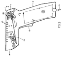
- Figure 1 illustrates a front view of a scanning device in the form of a hand-held, gun-shaped laser scanning head constructed pursuant to the invention;
- Figure 2 illustrates a front perspective view of the scanning device of Fig. 1 during operation thereof, schematically connected to other components of a laser scanning system;
- Figure 3 illustrates a sectional view taken along line 3 - 3 in Fig. 1;
- Figure 4 illustrates, on an enlarged scale, a sectional view through a portion of a printed circuit board having the scanning arrangement with a scanning motor constructed pursuant to the invention mounted thereon, taken along line 4 - 4 in Fig. 3;
- Figure 5 illustrates a sectional view taken along line 5 - 5 in Fig. 4;
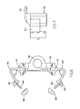
- Figure 6 illustrates a top plan view of the support member for mounting the scan mirror and the scanning motor components including a mylar leaf spring;
- Figure 7 illustrates an elevational end view of the support structure of Fig. 6;
- Figure 8 illustrates a plan view of a trunnion for mounting the support structure of Fig. 7 on a printed circuit board;
- Figure 9 illustrates an end view of the trunnion of Fig. 8;
- Figure 10 illustrates an elevational view of a post and bracket structure for attaching the scan mirror and portion of the scanning motor to the support bracket;
- Figure 10a illustrates a cross-sectional view through the post of Fig. 10;
- Figure 11 illustrates an elevational side view of the arm and bracket for attaching the magnet component of the scanning motor to the attaching post for the scan mirror;
- Figure 12 illustrates a top plan view of the scan motor attachment shown in Fig. 11;
- Figure 13 illustrates a top plan view of the post and bracket arrangement for mounting the scan mirror fastening the scanning motor; and
- Figure 14 illustrates a front view of the mylar leaf spring.
- Referring now more specifically to the drawings, and particularly Figs. 1 to 3, the invention relates to a laser scanning device of which is readily adapted for reading, scanning and/or analyzing symbols, for example, bar code symbols or any of the symbols as detailed hereinbefore.
- Turning now to Fig. 1, there is illustrated one embodiment of the present invention in the form of a generally hand-held
reading head 10 that includes a generally gun-shaped housing having ahandle portion 12 of generally rectangular cross-section and generally elongated along a handle axis, and a generally horizontally-elongated barrel orbody portion 11. The cross-sectional dimension and overall size of thehandle portion 12 is cut that thehead 10 conveniently can fit and be held in a user's hand. The body and handle portions are constituted of a lightweight, resilient, shock-resistant, self-supporting material, such as a synthetic plastic material. The plastic housing preferably is injection-molded, but can be vacuum-formed or blow-molded to form a thin, hollow shell which bounds an interior space whose volume measures less than a value on the order of 50 cubic inches and, in some applications, the volume is on the order of 25 cubic inches or less. Such specific values are not intended to be self-limiting, but to provide a general approximation of the overall maximum size and volume of thehead 10. The shell is formed of twohousing parts line 12c. - As considered in an intended position of use as shown in Fig. 2, the
body portion 11 has a front prow region or nose having an inclined front wall 11 a. Thebody portion 11 also has a rear region or stern having a rear wall 11 b spaced rearwardly of the inclined front wall 11 a. Thebody portion 11 also has a top wall 11 c, and a pair ofopposed side walls 11 e, 11 between the top and bottom walls. The front wall 11 a is sloped relative to the top and bottom walls. - A manually-actuatable, and preferably depressible, trigger 13 is mounted for movement relative to the head in a forwardly-facing region where the handle and body portions meet and where the user's forefinger normally lies when the user grips the handle portion in the intended position of use.
- A
window 14 is stationarily mounted at the nose and is light-transmissive to allow laser light to pass from the interior to the exterior of the head, and vice versa. - A flexible, non-bulky, coil-type
electrical cable 15 with multiple freedoms of movement interconnects thehead 10 to the remainder of the components of the laser scanning system, such as a decode module and host device, as is known in the art. - A plurality of components are mounted in the head and, as explained below, at least some of them are actuated by the
trigger 13, either directly or indirectly, by means of a control microprocessor. One of the head components may be an actuatable laser light course (see Fig. 3). e.g. such as a semiconductor laser diode, operative, when actuated by thetrigger 13, for propagating and generating an incident laser beam whose light, as explained above, is at least marginally visible to the human eye. The emitted laser diode beam is highly divergent; diverges differently in different planes parallel and perpendicular to the longitudinal direction of beam propagation; is non-radially symmetrical, i.e. anamorphic; and has a beam cross-section resembling an oval. The diode may be of the continuous wave or pulse type. The diode requires a low voltage (e.g. 12 v DC or less) supplied by a power regulator and a battery (DC) source which may be provided within the head, or by a rechargeable battery pack accessory detachably mounted on the head, or by a power conductor in thecable 15 connected to the head from an external power supply (e.g. DC source). Diodes which emit laser light or different wavelengths are also within the scope of this invention. - Although the embodiment illustrated in Figures 1 and 2 is a hand-held one, the present invention may also be implemented in a fixed mount, tabletop, or other configurations.
- Having reference to the cross-sectional view shown in Fig. 3, an
optical assembly 30 is mounted in the device on a thin-flexible printedcircuit board 20, and is adjustably positioned relative to the board for optically modifying and directing the emitted light or laser beam along a specified optical path towards a reference plane which is located exteriorly of the device. A symbol to be read may be arranged in the vicinity of the reference plane, at the reference plane, or towards one side or at an opposite side thereof, in essence, anywhere within the depth of field of the applicably modified laser beam and within a range of working distances as measured relative to the laser device. Hereby, the light or laser beam reflects off the symbol as a specular component in one direction and as a scattered component in many directions, and that portion of the scattered laser light which travels along a second optical path away from the symbol back towards the scanning device is referred to as the returning light portion and is employed for providing the information relative to that provided on the symbol. - As shown in Fig. 3, the
optical assembly 30 may be similar to or identical with that disclosed in U. S. Patent 5,015,833, which is commonly assigned to the assignee of the present application and is incorporated herein by reference. Consequently, with the exception of relatively general comments, it is not considered to be necessary to repeat all of the information and details concerning the optical assembly. However, as is well known in this technology, the optical assembly may be constituted of a focusing lens, probably in the configuration of a plano-convex lens, and cooperating with an aperture for focusing the emitted laser or light beam at a reference plane. Suitable springs for adjusting the lens and other components may be incorporated in the optical assembly, including a light generating source, such as a laser diode for producing the required light to be projected against ascanning arrangement 36, pursuant to the present invention described in detail hereinbelow. - Referring now more specifically to the assembled components of the scanning arrangement as shown in Figs. 4 and 5 of the drawings, the
arrangement 36 includes anupstanding support member 40, as shown in Figs. 6 and 7, having a central portion in the shape of anelongate bracket 42 with extending generally L-shapedbent arms rectangular bracket 42 is mounted on the printedcircuit board 20 through the intermediary of suitable fasteners (not shown) extending throughholes 47 formed in the ends of the bracket and engaging into threadedbores 58 of atrunnion 60 and includes an aperturedcentral portion 48 for the swivable support of apost 50, as illustrated in Fig. 10, having a lower end extending through theboard 20, as shown in Figs. 8 and 9, positioned to extend across the lower surface of the printedcircuit board 20. Thepost 50 includes abracket member 52 to which there is fastened asuitable scan element 54, such as a flat scan mirror through fastener elements extending so as to be oscillatable about an axis y extending coaxially through the post. Fastened to thepost 50 is a projectingarm member 70 having amagnet 72 mounted on the outerdistal end 74 of the arm member, which magnet is adapted to be electrically alternatingly attracted to or repelled from the interior of an electrically energized andelectromagnetic coil structure 76 mounted on the printedcircuit board 20 by being movable into and out of an aperture in the coil, thereby resultingly oscillating thearm member 70 and post 50 and imparting a reciprocating oscillatory movement to thescan mirror 54. - In order to properly position the
scan mirror 54, and to essentially restore or bias the scan mirror towards its centered position, the distal ends 44, 46 of each of thebent arm members 42 of thestructure bracket 42 are provided with clamping components, such as in the shape of in cross-section hemisphericalcylindrical extensions dowels 64 cooperating withcomplementary clamping members notch portion 80 formed in thepost 50, and also in engagement with the arm supporting the magnet, is aflat leaf spring 80 constituted from a sheet of mylar, as shown in Fig. 14 of the drawings, whereby the central portion of themylar leaf spring 80 hasholes 82 therein adapted to be engaged by fasteners or dowels extending from the arm mounting the magnet so as to clamp the spring to therotatable post 50 supporting thescan mirror 54, while the opposite ends 84, 86 of the mylar spring each include holes 88, 90 adapted to engage over thedowels 64 extending between the respective hemisphericallycross-sectional clamping elements arms 42 so as to be fixedly engaged therebetween. Hereby, the spring is bent into two arm segments, for example, at a right angle or 90 to each other extending from the attachment to thepost 50 towards eachend flexible arm members 42. This will provide a resilient biasing restoring action on thescan mirror 54 opposite the oscillatory movement imparted to the scan mirror by the energizing effect imposed on the magnet, thereby reciprocating the mirror between its end positions. In effect, during the operation of the scanning arrangement, each time an energizing pulse is applied to the coil, the magnet is drawn into the central opening or aperture into the coil, thereby pulling all of the oscillatable components therewith, and concurrently bending the leaf spring. As illustrated in Fig. 4 of the drawings, each of the arms of the leaf spring is generally planar, while upon being displaced responsive to the oscillation of the magnet, each arm of the leaf spring is bent so as to store energy therein. Upon being bent, the leaf spring then releases its stored energy, thereby displacing the magnet and the scan mirror back into and past its centered normal at rest position, with the entire assembly oscillating in a damp manner. This particular structure thus ensures a controlled oscillation of the scan mirror between the two end positions thereof so as to afford a uniform scan operation for reading information on a target object. - With the exception of the construction of the
leaf spring 80 being constituted from mylar, the remaining components of thescanning arrangement 36 as set forth hereinabove, with the exception of the scan mirror, may consist of a molded plastic material; for example, such as lexan or the like, and in the simplicity of construction by modularly mounting the entire scanning arrangement on the printedcircuit board 20 effectively protects the arrangement against externally produced shocks and impacts encountered during any possible dropping or rough handling of the scanning device while concurrently rendering the construction thereof inexpensive in nature and easily and quickly capable of being serviced. - From the foregoing, it readily appears to one skilled in the art that the scanning arrangement pursuant to the invention clearly and advantageously provides features which are not at all disclosed nor contemplated in the technology.
- While there has been shown and described what are considered to be a preferred embodiment of the invention, it will of course be understood that various modifications and changes in form or detail could readily be made without departing from the spirit of the invention. It is therefore intended that the invention be not limited to the exact form and detail herein shown and described, nor to anything less than the whole of the invention herein disclosed as hereinafter claimed.
-
- 1. A scanning device for reading indicia having parts of different light reflectivity by directing a beam of light toward the indicia and collecting light reflected from the indicia; comprising:
- (a) a single printed circuit board fixedly positioned in said device;
- (b) light generating means and optical means mounted on said circuit board for producing and directing a focused beam of light; and
- (c) a scanning arrangement mounted on said circuit board in spaced relationship from said light generating and optical means, said scanning arrangement including means for mounting a scanning element for reciprocatory movement; an upstanding support member fastened to said circuit board including a central portion having said scanning element mounting means connected therewith; scanning motor means operatively connected with said scanning element mounting means for imparting said reciprocatory movement to said scanning element, said support member having extending arm members at opposite ends; and a resiliently flexible leaf spring extending between said arm members and said means connecting said scanning motor means and said scanning element so as to provide a restoring force opposite the force exerted by said scanning motor means for normally biasing said scanning element into a central position intermediate opposite oscillatory end positions.
- 2. A scanning device as in 1, wherein said leaf spring is constituted from mylar and the remaining components of said scanning arrangement are each constituted of a molded plastic material.
- 3. A scanning device as in 1, wherein the free ends of each said arm member includes clamping means for grippingly engaging to adjacently located end of said leaf spring.
- 4. A scanning device as in 1, wherein said arm members are flexible.
- 5. A scanning device as in 4, wherein said arm members and said support member comprise an integrally molded unitary structure.
- 6. A scanning device as in 4, wherein fastening means at the junctures between said arm members and the support member attach said structure to the circuit board.
- 7. A scanning device as in 6, wherein said support member has a vertical central post portion having one end depending downwardly through an aperture in said circuit board; and trunnion means extending along the lower surface of said circuit board engaging said lower end of the post portion.
- 8. A scanning device as in 1, wherein said scanning motor means comprises a permanent magnet mounted on an oscillatable arm connected to the mounting means for said scanning element; and electromagnetic coils on said circuit board for alternatingly attracting and repelling said magnet so as to oscillate said arm and resultingly oscillate said scanning element.
- 9. A scanning device as in 8, wherein the center of said leaf springs is attached to said means for oscillating said permanent magnet.
- 10. A scanning device as in 7, wherein said scanning element mounting means is connected to said post portion for angular rotational movement relative thereto.
- 11. A scanning device as in 1, wherein said scanning element comprises a flat scan mirror.
- 12. A scanning device as in 3, wherein said arm members are bent such that the free distal ends extend towards each other, and said leaf spring forms an angled spring subtending an angle between the angled segments of said spring.
- 13. A method of reading indicia having parts of different light reflectivity by directing a beam of light toward the indicia and collecting light reflected from the indicia through the intermediary of a scanning device; comprising:
- (a) fixedly positioning a single printed circuit board in said scanning device;
- (b) mounting light generating means and optical means mounted on said circuit board for producing and directing a focused beam of light; and
- (c) mounting a scanning arrangement on said circuit board in spaced relationship from said light generating and optical means, said scanning arrangement including means for mounting a scanning element for reciprocatory movement; fastening an upstanding support member to said circuit board including a central portion having said scanning element mounting means connected therewith; operatively connecting scanning motor means with said scanning element mounting means for imparting said reciprocatory movement to said scanning element, said support member having extending arm members at opposite ends; and positioning a resiliently flexible leaf spring to extend between said arm members and said means connecting said scanning motor means and said scanning element so as to provide a restoring force opposite the force exerted by said scanning motor means for normally biasing said scanning element into a central position intermediate opposite oscillatory end positions.
- 14. A method as in 13, wherein said leaf spring is constituted from mylar and the remaining components of said scanning arrangement are each constituted of a molded plastic material.
- 15. A method as in 13, wherein the free ends of each said arm member includes clamping means for grippingly engaging to adjacently located end of said leaf spring.
- 16. A method as in 13, wherein said arm members are resiliently flexible.
- 17. A method as in 16, wherein said arm members and said support member comprise an integrally molded unitary structure.
- 18. A method as in 16, wherein fastening means at the junctures between said arm members and the support member attach said structure to the circuit board.
- 19. A method as in 13, wherein said support member has a vertical central post portion having one end depending downwardly through an aperture in said circuit board; and trunnion means extending along the lower surface of said circuit board engaging said lower end of the post portion.
- 20. A method as in 13, wherein said scanning motor means comprises a permanent magnet mounted on an oscillatable arm connected to the mounting means for said scanning element; and electromagnetic coils on said circuit board for alternatingly attracting and repelling said magnet so as to oscillate said arm and resultingly oscillate said scanning element.
- 21. A method as in 20, wherein the center of said leaf springs is attached to said means for oscillating said permanent magnet.
- 22. A method as in 19, wherein said scanning element mounting means is connected to said post portion for angular rotational movement relative thereto.
- 23. A method as in 13, wherein said scanning element comprises a plano-concave scan mirror.
- 24. A method as in 15, wherein said arm members are bent such that the free distal ends extend towards each other, and said leaf spring forms an angled spring subtending an angle between the angled segments of said spring.
Claims (14)
Applications Claiming Priority (2)
| Application Number | Priority Date | Filing Date | Title |
|---|---|---|---|
| US812923 | 1991-12-24 | ||
| US07/812,923 US5262627A (en) | 1989-10-30 | 1991-12-24 | Scanning arrangement and method |
Publications (3)
| Publication Number | Publication Date |
|---|---|
| EP0548951A2 true EP0548951A2 (en) | 1993-06-30 |
| EP0548951A3 EP0548951A3 (en) | 1994-01-19 |
| EP0548951B1 EP0548951B1 (en) | 1998-04-08 |
Family
ID=25210977
Family Applications (1)
| Application Number | Title | Priority Date | Filing Date |
|---|---|---|---|
| EP92121900A Expired - Lifetime EP0548951B1 (en) | 1991-12-24 | 1992-12-23 | Scanning arrangement and method |
Country Status (9)
| Country | Link |
|---|---|
| US (1) | US5262627A (en) |
| EP (1) | EP0548951B1 (en) |
| JP (1) | JP3213644B2 (en) |
| CN (1) | CN1029877C (en) |
| AT (1) | ATE164959T1 (en) |
| CA (1) | CA2084212C (en) |
| DE (1) | DE69225055T2 (en) |
| ES (1) | ES2117027T3 (en) |
| TW (1) | TW233356B (en) |
Cited By (9)
| Publication number | Priority date | Publication date | Assignee | Title |
|---|---|---|---|---|
| EP0653723A2 (en) * | 1993-11-17 | 1995-05-17 | Symbol Technologies, Inc. | Laser scanning system and scanning method for reading 1-d and 2-d barcode symbols |
| WO2001026036A2 (en) * | 1999-10-04 | 2001-04-12 | Welch Allyn Data Collection, Inc. | Imaging module for optical reader |
| US6371374B1 (en) | 1998-07-08 | 2002-04-16 | Welch Allyn Data Collection, Inc. | Adjustable illumination system for a barcode scanner |
| US6550679B2 (en) | 1998-07-08 | 2003-04-22 | Hand Held Products, Inc. | Image sensor mounting system |
| US6607128B1 (en) | 1998-07-08 | 2003-08-19 | Welch Allyn Data Collection Inc. | Optical assembly for barcode scanner |
| US6659350B2 (en) | 2000-11-01 | 2003-12-09 | Hand Held Products | Adjustable illumination system for a barcode scanner |
| US6832725B2 (en) | 1999-10-04 | 2004-12-21 | Hand Held Products, Inc. | Optical reader comprising multiple color illumination |
| EP2282283A3 (en) * | 1998-03-20 | 2011-11-30 | Symbol Technologies, Inc. | Bar code reader with an integrated scanning component module mountable on printed circuit board |
| US9076054B2 (en) | 1999-10-04 | 2015-07-07 | Hand Held Products, Inc. | Image sensor based optical reader |
Families Citing this family (50)
| Publication number | Priority date | Publication date | Assignee | Title |
|---|---|---|---|---|
| US5552592A (en) * | 1989-10-30 | 1996-09-03 | Symbol Technologies, Inc. | Slim scan module with dual detectors |
| US5616908A (en) * | 1991-09-17 | 1997-04-01 | Metrologic Instruments, Inc. | Automatic countertop laser scanner with flickering laser scanner beam for improved visibility thereof during bar code symbol reading |
| US5844227A (en) * | 1993-11-24 | 1998-12-01 | Metrologic Instruments, Inc. | Automatic hand-supportable omnidirectional laser projection scanner with scan-head directed projection axis for intuitive hand-supported omnidirectional scanning of bar code symbols within a narrowly confined scanning volume extending thereabout |
| US5340973A (en) * | 1990-09-17 | 1994-08-23 | Metrologic Instruments, Inc. | Automatic laser scanning system and method of reading bar code symbols using same |
| US6286760B1 (en) | 1994-08-17 | 2001-09-11 | Metrologic Instruments, Inc. | Automatic hand-supportable laser projection scanner for omni-directional reading of bar code symbols within a narrowly confined scanning volume |
| US5340971A (en) * | 1990-09-17 | 1994-08-23 | Metrologic Instruments, Inc. | Automatic bar code reading system having selectable long range and short range modes of operation |
| US6283375B1 (en) | 1990-09-10 | 2001-09-04 | Metrologic Instruments, Inc. | Automatically-activated hand-supportable laser scanning bar code symbol reading system with data transmission activation switch |
| US5796091A (en) * | 1993-11-24 | 1998-08-18 | Metrologic Instruments, Inc. | Automatic hand-supportable omnidirectional laser projection scanner with handle-controllable projection axis |
| US5756982A (en) * | 1990-09-11 | 1998-05-26 | Metrologic Instruments, Inc. | Body-wearable automatic laser scanner with power-conserving control subsystem |
| US6257492B1 (en) | 1990-09-10 | 2001-07-10 | Peter Bressler | Combination hand-held and counter-top omni-directional scanner |
| US6182898B1 (en) | 1993-11-24 | 2001-02-06 | Metrologic Instruments, Inc. | Bar code scanner with intuitive head aiming and collimated scan volume |
| US6651890B2 (en) | 1990-09-10 | 2003-11-25 | Sung Ho Byun | Combination hand-held and counter-top omnidirectional scanner |
| US5942743A (en) * | 1994-08-17 | 1999-08-24 | Metrologic Instruments, Inc. | Portable automatic hand-supportable omnidirectional laser projection scanner with power conserving control system |
| US6607133B2 (en) | 1990-09-10 | 2003-08-19 | Metrologic Instruments, Inc. | Automatically-activated hand-supportable laser scanning bar code symbol reading system with data transmission activation switch |
| US6874689B2 (en) | 1990-09-11 | 2005-04-05 | Metrologic Instruments, Inc. | Laser beam scanning device employing a scanning element having a flexible photo-etched gap region disposed between an anchored base portion and a light beam deflecting portion having a natural frequency of oscillation tuned by the physical dimensions of said flexible photo-etched gap region and forcibly oscillated about a fixed pivot point at an electronically-controlled frequency of oscillation substantially different from said natural resonant frequency of oscillation |
| US6227450B1 (en) | 1990-09-11 | 2001-05-08 | Metrologic Instruments, Inc. | Electronically-controlled mechanically-damped off-resonant light beam scanning mechanism and code symbol readers employing the same |
| US6742709B2 (en) | 1990-09-11 | 2004-06-01 | Metrologic Instruments, Inc. | Bar code symbol reading system employing electronically-controlled raster-type laser scanner for reading bar code symbols during hands-on and hands-free modes of operation |
| US7156310B2 (en) * | 1990-09-17 | 2007-01-02 | Metrologic Instruments, Inc. | Automatically-activated hand-supportable laser scanning bar code symbol reading system with data transmission activation switch |
| US5883375A (en) * | 1991-09-17 | 1999-03-16 | Metrologic Instruments, Inc. | Bar code symbol scanner having fixed and hand-held modes |
| US6189793B1 (en) | 1992-06-12 | 2001-02-20 | Metrologic Instruments, Inc. | Automatic laser projection scanner with improved activation controlling mechanism |
| US6527180B1 (en) * | 1993-11-17 | 2003-03-04 | Symbol Technologies, Inc. | Compact dual optical and scan modules in bar code readers |
| US6604684B1 (en) | 1993-11-24 | 2003-08-12 | Metrologic Instruments Inc. | Automatic optical projection scanner for omni-directional reading of bar code symbols within a confined scanning volume |
| US6860427B1 (en) | 1993-11-24 | 2005-03-01 | Metrologic Instruments, Inc. | Automatic optical projection scanner for omni-directional reading of bar code symbols within a confined scanning volume |
| US5874722A (en) * | 1994-07-19 | 1999-02-23 | Spectra-Physics Scanning Systems, Inc. | Compact scanner module mountable to pointing instrument |
| JP3379837B2 (en) * | 1994-10-27 | 2003-02-24 | 富士通株式会社 | Optical reader |
| US5543609A (en) * | 1994-10-28 | 1996-08-06 | Symbol Technologies, Inc. | Arrangement for and method of providing shock protection and vibration isolation for a scan module |
| AU3759495A (en) * | 1994-10-31 | 1996-05-23 | Psc Inc. | System for driving and controlling the motion of an oscillatory electromechanical system especially suitable for use in an optical scanner |
| WO1996013795A1 (en) * | 1994-10-31 | 1996-05-09 | Psc Inc. | Grip-conforming trigger mechanism for a hand-held bar code scanner |
| US6976626B2 (en) * | 1997-09-16 | 2005-12-20 | Metrologic Instruments, Inc. | Wireless bar code symbol driven portable data terminal (PDT) system adapted for single handed operation |
| US7124950B2 (en) * | 1997-09-16 | 2006-10-24 | Metrologic Instruments, Inc. | Bar code symbol reading system employing electronically-controlled raster-type laser scanner for reading bar code symbols during on hands-on and hands-free modes of operation |
| CA2262730A1 (en) | 1998-03-24 | 1999-09-24 | Symbol Technologies, Inc. | Bar code reader for portable computers |
| DE69920969T2 (en) | 1998-12-03 | 2005-10-20 | Metrologic Instruments Inc. | Automatically activated, portable laser bar code scanner with data transfer device |
| US7111786B2 (en) | 1998-12-03 | 2006-09-26 | Metrologic Instruments, Inc. | Automatically-activated wireless hand-supportable laser scanning bar code symbol reading system with data transmission activation switch and automatic communication range dependent control |
| US7097105B2 (en) * | 1998-12-03 | 2006-08-29 | Metrologic Instruments, Inc. | Automatically-activated hand-supportable omni-directional laser scanning bar code symbol reader having a user-selectable linear scanning menu-reading mode supported by a stroboscopically-pulsed omni-directional laser scanning pattern for improved bar code symbol navigation and alignment during menu-reading operations |
| CN100410958C (en) * | 2003-12-04 | 2008-08-13 | 武汉矽感科技有限公司 | Antifalse antipirated edition terninal equipment and method |
| US7331524B2 (en) * | 2005-05-31 | 2008-02-19 | Symbol Technologies, Inc. | Feedback mechanism for scanner devices |
| US7556203B2 (en) | 2005-06-27 | 2009-07-07 | Hand Held Products, Inc. | Method and system for linking a wireless hand held optical reader with a base unit or other wireless device |
| US8002183B2 (en) | 2005-10-20 | 2011-08-23 | Metrologic Instruments, Inc. | Scanner flipper integrity indicator |
| US7686216B2 (en) * | 2006-06-13 | 2010-03-30 | Hand Held Products, Inc. | Method and apparatus for uniquely associating a bar code reading terminal to a cash register in a retail store network |
| US7832641B2 (en) | 2007-05-24 | 2010-11-16 | Metrologic Instruments, Inc. | Scanner switched to active state by sensed movement in quiescent scanning mechanism |
| US8059324B2 (en) | 2009-09-23 | 2011-11-15 | Metrologic Instruments, Inc. | Scan element for use in scanning light and method of making the same |
| US8390909B2 (en) | 2009-09-23 | 2013-03-05 | Metrologic Instruments, Inc. | Molded elastomeric flexural elements for use in a laser scanning assemblies and scanners, and methods of manufacturing, tuning and adjusting the same |
| US8294969B2 (en) | 2009-09-23 | 2012-10-23 | Metrologic Instruments, Inc. | Scan element for use in scanning light and method of making the same |
| JPWO2011040492A1 (en) * | 2009-09-29 | 2013-02-28 | 株式会社オプトエレクトロニクス | Optical information reader |
| US8915439B2 (en) | 2012-02-06 | 2014-12-23 | Metrologic Instruments, Inc. | Laser scanning modules embodying silicone scan element with torsional hinges |
| US8746563B2 (en) | 2012-06-10 | 2014-06-10 | Metrologic Instruments, Inc. | Laser scanning module with rotatably adjustable laser scanning assembly |
| USD692004S1 (en) * | 2012-08-31 | 2013-10-22 | Megaviz Limited | Barcode scanner and radio frequency identification reader combo |
| JP6884514B2 (en) * | 2015-04-28 | 2021-06-09 | 株式会社デンソーウェーブ | Optical information reader |
| US11354525B2 (en) | 2015-04-28 | 2022-06-07 | Denso Wave Incorporated | Optical information reader manually handled by users |
| CN105095821B (en) * | 2015-08-11 | 2017-12-29 | 深圳市合杰电子有限公司 | A kind of optical mask scanner |
Citations (4)
| Publication number | Priority date | Publication date | Assignee | Title |
|---|---|---|---|---|
| WO1985005464A1 (en) * | 1984-05-24 | 1985-12-05 | The Commonwealth Of Australia Care Of The Secretar | Focal plane scanning device |
| US4902083A (en) * | 1988-05-31 | 1990-02-20 | Reflection Technology, Inc. | Low vibration resonant scanning unit for miniature optical display apparatus |
| US5015833A (en) * | 1988-10-31 | 1991-05-14 | Symbol Technologies, Inc. | Scan board module for laser scanners |
| EP0456095A2 (en) * | 1990-05-08 | 1991-11-13 | Symbol Technologies, Inc. | Scanning arrangement |
Family Cites Families (34)
| Publication number | Priority date | Publication date | Assignee | Title |
|---|---|---|---|---|
| US1202446A (en) * | 1915-02-12 | 1916-10-24 | Western Electric Co | Electromagnetic device. |
| US1552186A (en) * | 1924-04-12 | 1925-09-01 | Carnegie Inst Of Washington | Seismometer |
| US1800601A (en) * | 1929-01-07 | 1931-04-14 | Centeno Melchor | Television apparatus |
| USRE18761E (en) * | 1930-02-21 | 1933-03-07 | centeno v- | |
| US2989643A (en) * | 1952-07-11 | 1961-06-20 | Wayne W Scanlon | Infra-red image system |
| US2971054A (en) * | 1956-08-03 | 1961-02-07 | Varo Mfg Co Inc | Scanning devices and systems |
| US3087373A (en) * | 1960-08-26 | 1963-04-30 | Barnes Eng Co | Oscillatory scanning system |
| US3532408A (en) * | 1968-05-20 | 1970-10-06 | Bulova Watch Co Inc | Resonant torsional oscillators |
| US3642343A (en) * | 1970-04-30 | 1972-02-15 | Gen Motors Corp | Linear optical scanning device |
| IT1008823B (en) * | 1974-02-11 | 1976-11-30 | Siv Spa | ELECTRIC AC CONNECTION DEVICE FOR ELECTRICALLY HEATED GLASS SHEETS |
| US3981566A (en) * | 1974-09-23 | 1976-09-21 | Eastman Kodak Company | Lever-action mountings for beam steerer mirrors |
| US3998092A (en) * | 1974-12-23 | 1976-12-21 | Bruce Sargent Maccabee | Simple systems for light beam modulation by acoustic surface waves |
| NL174608C (en) * | 1975-10-20 | 1984-07-02 | Philips Nv | METHOD FOR THE MANUFACTURE OF A TILT MIRROR DEVICE AND A TILT MIRROR DEVICE MADE ACCORDING TO THIS METHOD |
| JPS53108403A (en) * | 1977-03-04 | 1978-09-21 | Sony Corp | Mirror supporting device for video disc |
| US4199219A (en) * | 1977-04-22 | 1980-04-22 | Canon Kabushiki Kaisha | Device for scanning an object with a light beam |
| JPS54111362A (en) * | 1978-02-20 | 1979-08-31 | Canon Inc | Two-dimensional scanning optical system |
| US4360798A (en) * | 1978-05-31 | 1982-11-23 | Symbol Technologies, Inc. | Portable laser scanning arrangement for and method of evaluating and validating bar code symbols |
| US4251798A (en) * | 1978-05-31 | 1981-02-17 | Symbol Technologies | Portable laser scanning arrangement for and method of evaluating and validating bar code symbols |
| US4593186A (en) * | 1980-02-29 | 1986-06-03 | Symbol Technologies, Inc. | Portable laser scanning system and scanning methods |
| US4387297B1 (en) * | 1980-02-29 | 1995-09-12 | Symbol Technologies Inc | Portable laser scanning system and scanning methods |
| US4496831A (en) * | 1980-02-29 | 1985-01-29 | Symbol Technologies, Inc. | Portable laser scanning system and scanning methods |
| US4369361A (en) * | 1980-03-25 | 1983-01-18 | Symbol Technologies, Inc. | Portable, stand-alone, desk-top laser scanning workstation for intelligent data acquisition terminal and method of scanning |
| US4409470A (en) * | 1982-01-25 | 1983-10-11 | Symbol Technologies, Inc. | Narrow-bodied, single-and twin-windowed portable laser scanning head for reading bar code symbols |
| US4632501A (en) * | 1984-02-16 | 1986-12-30 | General Scanning, Inc. | Resonant electromechanical oscillator |
| DE3542154A1 (en) * | 1984-12-01 | 1986-07-10 | Ngk Spark Plug Co | LIGHT DEFLECTOR |
| EP0367298B1 (en) * | 1985-02-28 | 1992-07-22 | Symbol Technologies, Inc. | Portable laser diode scanning head |
| US4732440A (en) * | 1985-10-22 | 1988-03-22 | Gadhok Jagmohan S | Self resonant scanning device |
| US4816661A (en) * | 1986-12-22 | 1989-03-28 | Symbol Technologies, Inc. | Scan pattern generators for bar code symbol readers |
| US4808804A (en) * | 1987-01-28 | 1989-02-28 | Symbol Technologies, Inc. | Bar code symbol readers with variable spot size and/or working distance |
| FR2625335A1 (en) * | 1987-12-24 | 1989-06-30 | Castelo Veronique | OSCILLATING MIRROR DEVICE FOR THE DEVIATION OF ELECTROMAGNETIC RAYS |
| US4871904A (en) * | 1987-12-28 | 1989-10-03 | Symbol Technologies, Inc. | Multidirectional optical scanner |
| US4919500A (en) * | 1988-09-09 | 1990-04-24 | General Scanning, Inc. | Torsion bar scanner with damping |
| US4962980A (en) * | 1989-01-23 | 1990-10-16 | Metrologic Instruments, Inc. | Laser scanner engine with folded beam path |
| EP0471291B1 (en) * | 1990-08-07 | 1997-04-16 | Omron Corporation | Optical scanner |
-
1991
- 1991-12-24 US US07/812,923 patent/US5262627A/en not_active Expired - Lifetime
-
1992
- 1992-12-01 CA CA002084212A patent/CA2084212C/en not_active Expired - Lifetime
- 1992-12-23 AT AT92121900T patent/ATE164959T1/en active
- 1992-12-23 ES ES92121900T patent/ES2117027T3/en not_active Expired - Lifetime
- 1992-12-23 DE DE69225055T patent/DE69225055T2/en not_active Expired - Lifetime
- 1992-12-23 EP EP92121900A patent/EP0548951B1/en not_active Expired - Lifetime
- 1992-12-24 CN CN92114485.7A patent/CN1029877C/en not_active Expired - Lifetime
- 1992-12-24 JP JP34415692A patent/JP3213644B2/en not_active Expired - Fee Related
-
1993
- 1993-03-08 TW TW082101673A patent/TW233356B/zh not_active IP Right Cessation
Patent Citations (4)
| Publication number | Priority date | Publication date | Assignee | Title |
|---|---|---|---|---|
| WO1985005464A1 (en) * | 1984-05-24 | 1985-12-05 | The Commonwealth Of Australia Care Of The Secretar | Focal plane scanning device |
| US4902083A (en) * | 1988-05-31 | 1990-02-20 | Reflection Technology, Inc. | Low vibration resonant scanning unit for miniature optical display apparatus |
| US5015833A (en) * | 1988-10-31 | 1991-05-14 | Symbol Technologies, Inc. | Scan board module for laser scanners |
| EP0456095A2 (en) * | 1990-05-08 | 1991-11-13 | Symbol Technologies, Inc. | Scanning arrangement |
Cited By (13)
| Publication number | Priority date | Publication date | Assignee | Title |
|---|---|---|---|---|
| EP0653723A2 (en) * | 1993-11-17 | 1995-05-17 | Symbol Technologies, Inc. | Laser scanning system and scanning method for reading 1-d and 2-d barcode symbols |
| EP0653723A3 (en) * | 1993-11-17 | 2000-02-09 | Symbol Technologies, Inc. | Laser scanning system and scanning method for reading 1-d and 2-d barcode symbols |
| EP2282283A3 (en) * | 1998-03-20 | 2011-11-30 | Symbol Technologies, Inc. | Bar code reader with an integrated scanning component module mountable on printed circuit board |
| US7306155B2 (en) | 1998-07-08 | 2007-12-11 | Hand Held Products, Inc. | Image sensor assembly for optical reader |
| US6371374B1 (en) | 1998-07-08 | 2002-04-16 | Welch Allyn Data Collection, Inc. | Adjustable illumination system for a barcode scanner |
| US6550679B2 (en) | 1998-07-08 | 2003-04-22 | Hand Held Products, Inc. | Image sensor mounting system |
| US6607128B1 (en) | 1998-07-08 | 2003-08-19 | Welch Allyn Data Collection Inc. | Optical assembly for barcode scanner |
| US8096472B2 (en) | 1998-07-08 | 2012-01-17 | Hand Held Products, Inc. | Image sensor assembly for optical reader |
| US6832725B2 (en) | 1999-10-04 | 2004-12-21 | Hand Held Products, Inc. | Optical reader comprising multiple color illumination |
| WO2001026036A3 (en) * | 1999-10-04 | 2002-01-10 | Welch Allyn Data Collection | Imaging module for optical reader |
| WO2001026036A2 (en) * | 1999-10-04 | 2001-04-12 | Welch Allyn Data Collection, Inc. | Imaging module for optical reader |
| US9076054B2 (en) | 1999-10-04 | 2015-07-07 | Hand Held Products, Inc. | Image sensor based optical reader |
| US6659350B2 (en) | 2000-11-01 | 2003-12-09 | Hand Held Products | Adjustable illumination system for a barcode scanner |
Also Published As
| Publication number | Publication date |
|---|---|
| TW233356B (en) | 1994-11-01 |
| CN1077297A (en) | 1993-10-13 |
| EP0548951A3 (en) | 1994-01-19 |
| DE69225055D1 (en) | 1998-05-14 |
| CA2084212C (en) | 2004-04-13 |
| JPH05266236A (en) | 1993-10-15 |
| ES2117027T3 (en) | 1998-08-01 |
| US5262627A (en) | 1993-11-16 |
| DE69225055T2 (en) | 1998-11-12 |
| ATE164959T1 (en) | 1998-04-15 |
| CN1029877C (en) | 1995-09-27 |
| EP0548951B1 (en) | 1998-04-08 |
| JP3213644B2 (en) | 2001-10-02 |
| CA2084212A1 (en) | 1993-06-25 |
Similar Documents
| Publication | Publication Date | Title |
|---|---|---|
| US5262627A (en) | Scanning arrangement and method | |
| EP0540781B1 (en) | High-speed scanning arrangement | |
| US5665954A (en) | Electro-optical scanner module having dual electro-magnetic coils | |
| EP0788068B1 (en) | Scanning arrangement | |
| JP2717043B2 (en) | Mirrorless scanner | |
| US5945659A (en) | Electromagnetically activated scanner with suspended scanner component and stop | |
| US5280163A (en) | Drive circuit for resonant motors | |
| US5422471A (en) | Scanning device for scanning a target, scanning motor for the device and a method of utilization thereof | |
| US5486944A (en) | Scanner module for symbol scanning system | |
| US4896026A (en) | Laser diode scanner with improved shock mounting | |
| US5543610A (en) | Compact bar code scanning arrangement | |
| US6142379A (en) | Compact bar code scanner with scan mirror jointly movable with drive component | |
| US5386107A (en) | Scanning arrangement and method in which the focus is varied in operative correlation with the scanning angle | |
| US5481099A (en) | Scanning arrangement for the implementation of omni-directional scanning patterns over indicia | |
| WO2005109072A2 (en) | Synchronous and resonant drives for producing multiple scan line pattern for electro-optically reading indicia | |
| US6491225B1 (en) | Electro-optical reader with electronic stylus | |
| US6722566B1 (en) | Electro-optical scan module using selectable mirrors | |
| US6715681B2 (en) | Scanning module for single line and raster scanning using dual lasers | |
| EP0827102B1 (en) | Compact bar code scanning arrangement | |
| US6932274B2 (en) | Vibration reduction in electro-optical readers | |
| US5583331A (en) | Arrangement for compensating for scan line curvature | |
| US6712274B2 (en) | Permanent visual shock indicator | |
| US6988663B2 (en) | Movable scanning array in electro-optical readers | |
| EP0624852A2 (en) | Scanner module for symbol scanning system |
Legal Events
| Date | Code | Title | Description |
|---|---|---|---|
| PUAI | Public reference made under article 153(3) epc to a published international application that has entered the european phase |
Free format text: ORIGINAL CODE: 0009012 |
|
| AK | Designated contracting states |
Kind code of ref document: A2 Designated state(s): AT DE ES FR GB IT |
|
| PUAL | Search report despatched |
Free format text: ORIGINAL CODE: 0009013 |
|
| 17P | Request for examination filed |
Effective date: 19930924 |
|
| AK | Designated contracting states |
Kind code of ref document: A3 Designated state(s): AT DE ES FR GB IT |
|
| 17Q | First examination report despatched |
Effective date: 19960716 |
|
| GRAG | Despatch of communication of intention to grant |
Free format text: ORIGINAL CODE: EPIDOS AGRA |
|
| GRAG | Despatch of communication of intention to grant |
Free format text: ORIGINAL CODE: EPIDOS AGRA |
|
| GRAG | Despatch of communication of intention to grant |
Free format text: ORIGINAL CODE: EPIDOS AGRA |
|
| GRAH | Despatch of communication of intention to grant a patent |
Free format text: ORIGINAL CODE: EPIDOS IGRA |
|
| GRAH | Despatch of communication of intention to grant a patent |
Free format text: ORIGINAL CODE: EPIDOS IGRA |
|
| GRAA | (expected) grant |
Free format text: ORIGINAL CODE: 0009210 |
|
| AK | Designated contracting states |
Kind code of ref document: B1 Designated state(s): AT DE ES FR GB IT |
|
| REF | Corresponds to: |
Ref document number: 164959 Country of ref document: AT Date of ref document: 19980415 Kind code of ref document: T |
|
| REF | Corresponds to: |
Ref document number: 69225055 Country of ref document: DE Date of ref document: 19980514 |
|
| ITF | It: translation for a ep patent filed |
Owner name: CONCESSA PROROGA DI 6 MESI A PARTIRE DA:;JACOBACCI |
|
| REG | Reference to a national code |
Ref country code: ES Ref legal event code: FG2A Ref document number: 2117027 Country of ref document: ES Kind code of ref document: T3 |
|
| ET | Fr: translation filed | ||
| PLBE | No opposition filed within time limit |
Free format text: ORIGINAL CODE: 0009261 |
|
| STAA | Information on the status of an ep patent application or granted ep patent |
Free format text: STATUS: NO OPPOSITION FILED WITHIN TIME LIMIT |
|
| 26N | No opposition filed | ||
| REG | Reference to a national code |
Ref country code: GB Ref legal event code: IF02 |
|
| PGFP | Annual fee paid to national office [announced via postgrant information from national office to epo] |
Ref country code: AT Payment date: 20101122 Year of fee payment: 19 |
|
| PGFP | Annual fee paid to national office [announced via postgrant information from national office to epo] |
Ref country code: GB Payment date: 20101123 Year of fee payment: 19 |
|
| PGFP | Annual fee paid to national office [announced via postgrant information from national office to epo] |
Ref country code: FR Payment date: 20111205 Year of fee payment: 20 Ref country code: ES Payment date: 20111220 Year of fee payment: 20 |
|
| REG | Reference to a national code |
Ref country code: DE Ref legal event code: R082 Ref document number: 69225055 Country of ref document: DE Representative=s name: SCHUMACHER & WILLSAU PATENTANWALTSGESELLSCHAFT, DE |
|
| PGFP | Annual fee paid to national office [announced via postgrant information from national office to epo] |
Ref country code: DE Payment date: 20111230 Year of fee payment: 20 |
|
| PGFP | Annual fee paid to national office [announced via postgrant information from national office to epo] |
Ref country code: IT Payment date: 20111228 Year of fee payment: 20 |
|
| REG | Reference to a national code |
Ref country code: DE Ref legal event code: R071 Ref document number: 69225055 Country of ref document: DE |
|
| REG | Reference to a national code |
Ref country code: GB Ref legal event code: PE20 Expiry date: 20121222 |
|
| PG25 | Lapsed in a contracting state [announced via postgrant information from national office to epo] |
Ref country code: GB Free format text: LAPSE BECAUSE OF EXPIRATION OF PROTECTION Effective date: 20121222 |
|
| REG | Reference to a national code |
Ref country code: AT Ref legal event code: MK07 Ref document number: 164959 Country of ref document: AT Kind code of ref document: T Effective date: 20121223 |
|
| REG | Reference to a national code |
Ref country code: ES Ref legal event code: FD2A Effective date: 20140827 |
|
| PG25 | Lapsed in a contracting state [announced via postgrant information from national office to epo] |
Ref country code: ES Free format text: LAPSE BECAUSE OF EXPIRATION OF PROTECTION Effective date: 20121224 |