EP0550794A2 - Rotation encoder with absolute value position detection - Google Patents
Rotation encoder with absolute value position detection Download PDFInfo
- Publication number
- EP0550794A2 EP0550794A2 EP92115147A EP92115147A EP0550794A2 EP 0550794 A2 EP0550794 A2 EP 0550794A2 EP 92115147 A EP92115147 A EP 92115147A EP 92115147 A EP92115147 A EP 92115147A EP 0550794 A2 EP0550794 A2 EP 0550794A2
- Authority
- EP
- European Patent Office
- Prior art keywords
- encoder
- switching element
- rotary encoder
- shaft
- measuring device
- Prior art date
- Legal status (The legal status is an assumption and is not a legal conclusion. Google has not performed a legal analysis and makes no representation as to the accuracy of the status listed.)
- Granted
Links
Images


Classifications
-
- H—ELECTRICITY
- H03—ELECTRONIC CIRCUITRY
- H03M—CODING; DECODING; CODE CONVERSION IN GENERAL
- H03M1/00—Analogue/digital conversion; Digital/analogue conversion
- H03M1/002—Provisions or arrangements for saving power, e.g. by allowing a sleep mode, using lower supply voltage for downstream stages, using multiple clock domains or by selectively turning on stages when needed
-
- G—PHYSICS
- G01—MEASURING; TESTING
- G01D—MEASURING NOT SPECIALLY ADAPTED FOR A SPECIFIC VARIABLE; ARRANGEMENTS FOR MEASURING TWO OR MORE VARIABLES NOT COVERED IN A SINGLE OTHER SUBCLASS; TARIFF METERING APPARATUS; MEASURING OR TESTING NOT OTHERWISE PROVIDED FOR
- G01D5/00—Mechanical means for transferring the output of a sensing member; Means for converting the output of a sensing member to another variable where the form or nature of the sensing member does not constrain the means for converting; Transducers not specially adapted for a specific variable
- G01D5/12—Mechanical means for transferring the output of a sensing member; Means for converting the output of a sensing member to another variable where the form or nature of the sensing member does not constrain the means for converting; Transducers not specially adapted for a specific variable using electric or magnetic means
- G01D5/14—Mechanical means for transferring the output of a sensing member; Means for converting the output of a sensing member to another variable where the form or nature of the sensing member does not constrain the means for converting; Transducers not specially adapted for a specific variable using electric or magnetic means influencing the magnitude of a current or voltage
-
- G—PHYSICS
- G01—MEASURING; TESTING
- G01D—MEASURING NOT SPECIALLY ADAPTED FOR A SPECIFIC VARIABLE; ARRANGEMENTS FOR MEASURING TWO OR MORE VARIABLES NOT COVERED IN A SINGLE OTHER SUBCLASS; TARIFF METERING APPARATUS; MEASURING OR TESTING NOT OTHERWISE PROVIDED FOR
- G01D5/00—Mechanical means for transferring the output of a sensing member; Means for converting the output of a sensing member to another variable where the form or nature of the sensing member does not constrain the means for converting; Transducers not specially adapted for a specific variable
- G01D5/12—Mechanical means for transferring the output of a sensing member; Means for converting the output of a sensing member to another variable where the form or nature of the sensing member does not constrain the means for converting; Transducers not specially adapted for a specific variable using electric or magnetic means
- G01D5/244—Mechanical means for transferring the output of a sensing member; Means for converting the output of a sensing member to another variable where the form or nature of the sensing member does not constrain the means for converting; Transducers not specially adapted for a specific variable using electric or magnetic means influencing characteristics of pulses or pulse trains; generating pulses or pulse trains
- G01D5/24404—Interpolation using high frequency signals
-
- G—PHYSICS
- G01—MEASURING; TESTING
- G01P—MEASURING LINEAR OR ANGULAR SPEED, ACCELERATION, DECELERATION, OR SHOCK; INDICATING PRESENCE, ABSENCE, OR DIRECTION, OF MOVEMENT
- G01P3/00—Measuring linear or angular speed; Measuring differences of linear or angular speeds
- G01P3/42—Devices characterised by the use of electric or magnetic means
- G01P3/44—Devices characterised by the use of electric or magnetic means for measuring angular speed
- G01P3/48—Devices characterised by the use of electric or magnetic means for measuring angular speed by measuring frequency of generated current or voltage
- G01P3/481—Devices characterised by the use of electric or magnetic means for measuring angular speed by measuring frequency of generated current or voltage of pulse signals
- G01P3/489—Digital circuits therefor
-
- H—ELECTRICITY
- H03—ELECTRONIC CIRCUITRY
- H03M—CODING; DECODING; CODE CONVERSION IN GENERAL
- H03M1/00—Analogue/digital conversion; Digital/analogue conversion
- H03M1/12—Analogue/digital converters
- H03M1/22—Analogue/digital converters pattern-reading type
- H03M1/24—Analogue/digital converters pattern-reading type using relatively movable reader and disc or strip
- H03M1/28—Analogue/digital converters pattern-reading type using relatively movable reader and disc or strip with non-weighted coding
- H03M1/30—Analogue/digital converters pattern-reading type using relatively movable reader and disc or strip with non-weighted coding incremental
- H03M1/308—Analogue/digital converters pattern-reading type using relatively movable reader and disc or strip with non-weighted coding incremental with additional pattern means for determining the absolute position, e.g. reference marks
Definitions
- the invention relates to an encoder for absolute value position detection according to the preamble of claim 1.
- Encoders with an absolute value position detection are usually produced with an angle encoder disk and corresponding optical scanning devices (with, for example, LEDs, photodiodes, etc.). With the help of such a disk, the absolute angular position of an encoder shaft connected to this disk can be detected within an angular interval of 0 ° to 360 °. An angular range over several revolutions cannot be measured with a single disk, since its coding is naturally repeated after passing through one revolution.
- multi-rotary encoders were developed which, although they are only provided with an angle measuring device for detecting an angular range between 0 ° and 360 °, have a counting unit for detecting the completely completed revolutions.
- this combination enables the measuring range of the rotary encoder to be expanded to the maximum number of revolutions that can be detected by the counting unit, it also requires a constant power supply to the counting unit and the scanning device of the angle encoder disk. If the power supply to the counting unit is interrupted, the information it contains is lost. Switching off the power supply for the scanning device of the angular encoder also means that the counting unit can no longer register newly added or reversed revolutions. If the encoder shaft is rotated, the information about the absolute position is also lost in this case.
- the power supply of the encoder was buffered with the help of a battery or an accumulator.
- a multi-rotary encoder which has an angle coding disk with the corresponding optical detection device for detecting the absolute angle within one revolution and also comprises a separate magnetic signal transmitter and a counting unit for detecting fully completed revolutions.
- the named encoder is buffered by an external battery in the event of a power failure.
- Such a device has the disadvantage that it must always be connected at least to the auxiliary voltage supply in order not to lose the stored information.
- the encoder does not lose its information when external leads are disconnected and, furthermore, continues to record the movements of the encoder shaft. This is particularly necessary if a robot is being set up for test purposes and then dismantled into individual components for delivery.
- multi-turn encoders are desirable which also record the movements and positions of the individual components after or during the disassembly of the robot, so that the individual parts of the system do not need to be readjusted after they have been reassembled.
- the invention is therefore based on the object of proposing an inexpensive multi-rotary encoder that receives its information reliably without an external power supply and detects the absolute position of the encoder shaft over a large number of revolutions.
- the buffering in the event of a suspended external power supply is intended here very generously, ie over a period of several years.
- a rotary encoder in connection with a rotatable actuating part which is fixedly connected to the encoder shaft.
- the current that flows through this switching element in the closed state is limited by a series connection with a very high resistance.
- the logic circuit for pulse shaping and pulse selection which generates a logic signal per revolution of the encoder shaft from the signal of the switching element when the actuating part rotates, and the counting unit is also designed to be very high-resistance with the aid of at least one integrated circuit. Because of the extremely reduced power consumption in this way, the buffer battery or the accumulator can be chosen to be so small that it can be integrated into the rotary encoder unit, just like the electronic circuits mentioned.
- Such a rotary encoder provided with the components mentioned forms a compact structural unit and can function for years without an external power supply.
- a simple and robust embodiment of the invention is provided with a mechanically acting actuating part.
- Such an actuating part can be designed as a cam on the encoder shaft, which opens or closes two contact tongues with the revolutions of the encoder shaft.
- a magnetic ring which consists of a part of its circumference made of a permanent magnetic and the other part of non-magnetic material, the switching element being designed as a reed switch, which is opened once when the ring is turned or is closed.
- the current counter reading can be synchronized with the zero crossing of the angle measuring device.
- the counter which is coupled to the switching element switching in the respective direction of rotation before the zero crossing of the angle measuring device, always contains the correct value at the time of the zero crossing. Depending on the direction of rotation, the data output must be switched back and forth between the two counters.
- the closing effective angular range of the actuating part should be larger than the angle ⁇ and ⁇ 'enclosed by the two switching elements.
- the switching state of one switching element can be used to suppress one pulse per revolution from the pulses associated with the other switching element. This gives exactly one signal per revolution at the output of the logic circuit for each switching element.
- a square-wave signal can be generated on an edge of a switching state of a switching element, for example with the aid of a time delay element and a logic antivalence gate.
- the time delay of the time delay element gives exactly the width of the pulse.
- Switching back and forth between the two counters is preferably carried out with the aid of a multiplexer which switches the current counter content to the data output of the encoder in time with the most significant bit of the binary number read by the angle measuring device.
- a multiplexer which switches the current counter content to the data output of the encoder in time with the most significant bit of the binary number read by the angle measuring device.
- ASIC application-specific integrated circuit
- the angle measuring device can comprise an optical, a capacitive or an inductive scanning device.
- An angular coding part which is adapted to the scanning device and which rotates with the rotary encoder shaft, for example an angular coding disk for an optical scanning device, is to be provided here.
- Fig. 1 shows a rotary encoder 1 with a rotary encoder housing 2, which consists of a stator 3 and a housing cover 4. From below, an encoder shaft 5, which is rotatably supported by ball bearings 6, passes through the stator 3. The interior of the housing 2 is divided into an upper 8 and a lower part 9 by a shielding plate 7. The components are in the lower part 9 of the rotary encoder 1, which are provided for detecting the angular position within one revolution (single-turn encoder). In detail, these are an angle coding disk 10, which is illuminated from below by an optical transmitter unit 11. A receiver circuit board 12, which has optical sensors (not shown) and a receiver circuit, is located above the angle encoder disk 10.
- a magnet holder 13 which is plugged onto the encoder shaft 5.
- the part 14 of the magnet holder 13 inserted over the encoder shaft 5 passes through the shielding plate and projects into the lower part 9 of the rotary encoder 1.
- a magnetic ring 15 is attached to the magnet holder 13 at the top.
- a screw 16 fixes the magnet holder 13 on the encoder shaft 5.
- Above the magnetic ring there are two reed switches 17a, b within their shielding caps 18a, 18b.
- the two reed switches 17a, 17b are fastened on a printed circuit board 19 on which the circuits for signal shaping and selection, not shown, and the counters are constructed.
- a circuit board 20 At the top of the circuit board 19 there is a circuit board 20 with a DC voltage source and a battery 21.
- the components in the lower part 9 of the rotary encoder work in the manner known from conventional angular rotary encoders for angular resolution within one revolution of the encoder shaft 5.
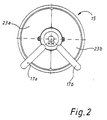
- the arrangement of the two reed switches 17a, 17b in the upper part 8 of the rotary encoder is shown in the schematic plan view of FIG. 2. They are at an angle of ⁇ or ⁇ ' ⁇ 45 ° to line 22, which corresponds to the zero crossing of the angle coding disk 10.
- the magnetic ring 15 is composed of a magnetic 23a and a non-magnetic part 23b, so that the reed switches are open when the magnetic part 23a of the magnetic ring is below them and are closed in the other case.
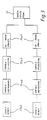
- the signals thus generated by the different switching states of the reed switches 17a, 17b are further processed in accordance with the block diagram shown in FIG. 3.
- the signals generated by the reed switches as pulse generators 17a, 17b enter an electronic circuit for pulse shaping 24, which forms a logic square pulse from each edge of its input signal. Subsequently, these square-wave pulses are selected in a circuit 25 for pulse selection in such a way that one square-wave pulse per revolution of the encoder shaft 5 is present at the output of this circuit.
- These impulses processed in this way are finally counted and stored in two counters. Since the two reed switches are at an angle .alpha. Or .alpha.
- the current counter reading of one counter therefore precedes the actual value in a certain direction of rotation, while the counter reading of the other counter lags behind.
- the counter with the respectively correct data stock is selected and switched through synchronously with the zero crossing of the angle coding disk 10 to its output.
- FIG. 4 shows a possible circuit for signal processing according to FIG. 3.
- An external power supply 28 and a lithium battery 29 supply the operating voltage for the following circuit as required.
- the two reed switches 17a, 17b switch the two power lines 30a, 30b against the via two very high-impedance and thus current-limiting resistors 31a, 31b Circuit ground.
- the voltages Va, Vb which are present in the signal lines 32a, 32b vary.
- a rectangular pulse A or B is generated at the output of the antivalence gates 34a, 34b by using a time delay element 33a, 33b and an relevance gate 34a, 34b.
- the time course of the various signals during the rotation of the encoder shaft is shown in FIG. 5.
- the top diagram shows the most significant bit MSB at the output of the single-turn encoder located in the lower part 9 of the encoder 1. This bit is set exactly with the zero crossing of the encoder shaft at time t o and switched to "Low” at 180 °.
- the two diagrams following below reflect the voltage curve Va, Vb in the signal lines 32a, 32b.
- the signal curve corresponds to that of the most significant bit MSB, but is offset by a time t ⁇ , t ⁇ ', in which the encoder shaft 5 rotates through the angles ⁇ and ⁇ '.
- the two following diagrams represent the pulses A, B at the output of the antivalence gates 34a, 34b.
- the width of the rectangular pulses A, B corresponds exactly to the time delay of the time delay elements 33a, 33b.
- the two diagrams below make it clear that only every second square-wave signal A ', B' is selected at the output of the AND gates 35. Accordingly, the lowest data bits, Da, Db of the two counters 26a, 26b are switched with the input of these square-wave signals A ', B'.
- the bottom one Based on the lowest data bit Da, Db, the diagram shows how the current counter reading corresponding to the direction of rotation, in this case Db, is output as data bit Dm in synchronism with the most significant bit of the angle coding disk MSB at the output of the multiplexer 27.
- a rotary encoder manages with buffer currents that are less than 10 ⁇ A due to the measures described.
- buffer currents that are less than 10 ⁇ A due to the measures described.
Abstract
Description
Die Erfindung betrifft einen Drehgeber zur Absolutwertspositionserfassung nach dem Oberbegriff des Anspruchs 1.The invention relates to an encoder for absolute value position detection according to the preamble of
Drehgeber mit einer Absolutwertpositionserfassung werden üblicherweise mit einer Winkelkodierscheibe und entsprechenden optischen Abtastvorrichtungen (mit z. B. LED, Photodioden etc.) hergestellt. Mit Hilfe einer solchen Scheibe kann die absolute Winkelposition einer mit dieser Scheibe verbundenen Drehgeberwelle innerhalb eines Winkelintervalls von 0° bis 360° erfaßt werden. Ein Winkelbereich über mehrere Umdrehungen ist mit einer einzigen Scheibe nicht meßbar, da sich ihre Kodierung nach Durchlaufen einer Umdrehung naturgemäß wiederholt.Encoders with an absolute value position detection are usually produced with an angle encoder disk and corresponding optical scanning devices (with, for example, LEDs, photodiodes, etc.). With the help of such a disk, the absolute angular position of an encoder shaft connected to this disk can be detected within an angular interval of 0 ° to 360 °. An angular range over several revolutions cannot be measured with a single disk, since its coding is naturally repeated after passing through one revolution.
Drehgeber mit einer absoluten Positionswerterfassung über mehrere Umdrehungen hinweg, sogenannte Multiturndrehgeber, sind infolge dessen in verschiedenen Ausführungsformen bekannt geworden.As a result, rotary encoders with an absolute position value acquisition over several revolutions, so-called multi-rotary encoders, are known in various embodiments.
So wurden beispielsweise mehrere Winkelkodierscheiben über ein Untersetzungsgetriebe miteinander verbunden zum Einsatz gebracht. Das Untersetzungsgetriebe bewirkt, daß die jeweils nachgeschaltete Winkelkodierscheibe bei einer vollständigen Umdrehung der vorgeschalteten Winkelkodierscheibe um eine, ihrem Auflösungsvermögen entsprechende Einheit gedreht wird. Die Funktionsweise eines solchen Multiturngebers ist mit einer herkömmlichen Analoguhr mit verschiedenen Zeigern vergleichbar. Bei einem solchen Drehgeber vervielfacht sich jedoch entsprechend der Anzahl der Kodierscheiben auch die Anzahl der optischen Abtastsysteme. Dieser Umstand sowie der Aufwand, der durch die erforderliche hohe Präzision für das Untersetzungsgetriebe verursacht wird, sind bei dieser Lösung von großem Nachteil.For example, several angle coding disks were connected to one another via a reduction gear brought. The reduction gear causes the respective downstream encoder to be rotated by a unit corresponding to its resolving power with one complete revolution of the upstream encoder. The operation of such a multiturn encoder can be compared to a conventional analog clock with different hands. With such an encoder, however, the number of optical scanning systems also multiplies according to the number of coding disks. This fact as well as the effort, which is caused by the high precision required for the reduction gear, are of great disadvantage with this solution.
Desweiteren wurden Multiturndrehgeber entwickelt, die zwar nur mit einer Winkelmeßvorrichtung zur Erfassung eines Winkelbereichs zwischen 0° und 360° versehen sind, jedoch zur Erfassung der vollständig durchlaufenen Umdrehungen eine Zähleinheit aufweisen. Diese Kombination ermöglicht zwar eine Erweiterung des Meßbereichs des Drehgebers auf die maximal von der Zähleinheit erfaßbare Anzahl von Umdrehungen, erfordert jedoch andererseits eine ständige Stromversorgung der Zähleinheit und der Abtastvorrichtung der Winkelkodierscheibe. Bei einer Unterbrechung der Stromversorgung der Zähleinheit geht die darin enthaltene Information verloren. Das Abschalten der Stromversorgung für die Abtastvorrichtung der Winkelkodierscheibe bewirkt außerdem, daß die Zähleinheit neu hinzukommende oder rückgängig gemachte Umdrehungen nicht mehr registrieren kann. Somit geht bei einer Verdrehung der Drehgeberwelle auch in diesem Fall die Information über die absolute Position verloren.Furthermore, multi-rotary encoders were developed which, although they are only provided with an angle measuring device for detecting an angular range between 0 ° and 360 °, have a counting unit for detecting the completely completed revolutions. Although this combination enables the measuring range of the rotary encoder to be expanded to the maximum number of revolutions that can be detected by the counting unit, it also requires a constant power supply to the counting unit and the scanning device of the angle encoder disk. If the power supply to the counting unit is interrupted, the information it contains is lost. Switching off the power supply for the scanning device of the angular encoder also means that the counting unit can no longer register newly added or reversed revolutions. If the encoder shaft is rotated, the information about the absolute position is also lost in this case.
Um diesen Nachteil zu beheben, wurde im folgenden die Stromversorgung des Drehgebers mit Hilfe einer Batterie oder eines Akkumulators gepuffert. So ist beispielsweise mit der europäischen Anmeldung EP 0 466 209 A2 ein Multiturndrehgeber bekannt geworden, der eine Winkelkodierscheibe mit der entsprechenden optischen Nachweisvorrichtung zur Erfassung des Absolutwinkels innerhalb einer Umdrehung aufweist und außerdem einen separaten magnetischen Signalgeber sowie eine Zähleinheit zur Erfassung vollständig durchlaufener Umdrehungen umfaßt. Der genannte Drehgeber wird bei Stromausfall über eine externe Batterie gepuffert.In order to remedy this disadvantage, the power supply of the encoder was buffered with the help of a battery or an accumulator. For example With the European application EP 0 466 209 A2 a multi-rotary encoder has become known, which has an angle coding disk with the corresponding optical detection device for detecting the absolute angle within one revolution and also comprises a separate magnetic signal transmitter and a counting unit for detecting fully completed revolutions. The named encoder is buffered by an external battery in the event of a power failure.
Eine solche Vorrichtung hat den Nachteil, daß sie ständig wenigstens mit der Hilfsspannungsversorgung verbunden sein muß, um die gespeicherte Information nicht zu verlieren. In vielen Fällen, beispielsweise bei einem Einsatz eines Multiturndrehgebers in einem Roboter, ist es jedoch wünschenswert, daß der Drehgeber seine Information beim Abklemmen äußerer Zuleitungen nicht verliert und darüberhinaus die Bewegungen der Drehgeberwelle weiterhin erfaßt. Dies ist insbesondere dann notwendig, wenn ein Roboter zu Testzwecken aufgebaut wird, um anschließend für die Lieferung wieder in einzelne Komponenten zerlegt zu werden. In einem solchen Fall sind Multiturndrehgeber wünschenswert, die auch nach oder während der Zerlegung des Roboters die Bewegungen und Stellungen der einzelnen Komponenten erfassen, so daß die Anlage nach deren Wiederzusammensetzen nicht in ihren Einzelteilen neu justiert werden braucht.Such a device has the disadvantage that it must always be connected at least to the auxiliary voltage supply in order not to lose the stored information. In many cases, for example when using a multi-rotary encoder in a robot, it is desirable that the encoder does not lose its information when external leads are disconnected and, furthermore, continues to record the movements of the encoder shaft. This is particularly necessary if a robot is being set up for test purposes and then dismantled into individual components for delivery. In such a case, multi-turn encoders are desirable which also record the movements and positions of the individual components after or during the disassembly of the robot, so that the individual parts of the system do not need to be readjusted after they have been reassembled.
Der Erfindung liegt daher die Aufgabe zugrunde, einen preiswerten Multiturndrehgeber vorzuschlagen, der ohne externe Spannungsversorgung seine Information zuverlässig erhält und die absolute Position der Drehgeberwelle über eine Vielzahl von Umdrehungen erfaßt. Die Pufferung im Falle abgehängter externer Spannungsversorgung soll hierbei sehr großzügig, d.h. über einen Zeitraum von mehreren Jahren, sichergestellt werden.The invention is therefore based on the object of proposing an inexpensive multi-rotary encoder that receives its information reliably without an external power supply and detects the absolute position of the encoder shaft over a large number of revolutions. The buffering in the event of a suspended external power supply is intended here very generously, ie over a period of several years.
Diese Aufgabe wird durch die kennzeichnenden Merkmale des Anspruchs 1 gelöst.This object is achieved by the characterizing features of
Demgemäß wird bei einem erfindungsgemäßen Drehgeber wenigstens ein mechanisch schließendes Schaltelement in Verbindung mit einem rotierbaren Betätigungsteil, das fest mit der Geberwelle verbunden ist, eingesetzt. Der Strom, der in geschlossenem Zustand über dieses Schaltelement fließt, wird über eine Reihenschaltung mit einem sehr hochohmigen Widerstands begrenzt. Außerdem wird die Logikschaltung zur Pulsformung und zur Pulsselektion, die aus dem Signal des Schaltelementes bei durchdrehendem Betätigungsteil ein logisches Signal pro Umdrehung der Geberwelle generiert sowie die Zähleinheit mit Hilfe von wenigstens einem integrierten Schaltkreis ebenfalls sehr hochohmig ausgelegt. Aufgrund des auf diese Weise extrem reduzierten Stromverbrauchs kann die Pufferbatterie bzw. der Akkumulator so klein gewählt werden, daß diese ebenso wie die genannten elektronischen Schaltungen in die Drehgebereinheit integrierbar ist. Ein derartiger, mit den genannten Komponenten versehener Drehgeber bildet eine kompakte bauliche Einheit und ist ohne externe Stromversorgung über Jahre hinaus funktionsfähig.Accordingly, in a rotary encoder according to the invention, at least one mechanically closing switching element is used in connection with a rotatable actuating part which is fixedly connected to the encoder shaft. The current that flows through this switching element in the closed state is limited by a series connection with a very high resistance. In addition, the logic circuit for pulse shaping and pulse selection, which generates a logic signal per revolution of the encoder shaft from the signal of the switching element when the actuating part rotates, and the counting unit is also designed to be very high-resistance with the aid of at least one integrated circuit. Because of the extremely reduced power consumption in this way, the buffer battery or the accumulator can be chosen to be so small that it can be integrated into the rotary encoder unit, just like the electronic circuits mentioned. Such a rotary encoder provided with the components mentioned forms a compact structural unit and can function for years without an external power supply.
Durch die in den Unteransprüchen genannten Maßnahmen sind vorteilhafte Ausführungen und Weiterentwicklungen der Erfindung möglich.Advantageous embodiments and further developments of the invention are possible through the measures mentioned in the subclaims.
Eine einfache und robuste Ausführung der Erfindung ist mit einem mechanisch wirkenden Betätigungsteil versehen. Ein solches Betätigungsteil kann als Nocken auf der Geberwelle ausgebildet sein, der zwei Kontaktzungen mit den Umdrehungen der Geberwelle öffnet bzw. schließt.A simple and robust embodiment of the invention is provided with a mechanically acting actuating part. Such an actuating part can be designed as a cam on the encoder shaft, which opens or closes two contact tongues with the revolutions of the encoder shaft.
Für ein berührungslos arbeitendes Betätigungsteil empfiehlt sich die Verwendung eines magnetischen Ringes, der über einen Teil seines Umfanges aus einem permanentmagnetischen und zum anderen Teil aus unmagnetischem Material besteht, wobei das Schaltelement als Reed Schalter ausgebildet ist, der bei einer Umdrehung dieses Ringes jeweils einmal geöffnet oder geschlossen wird.For a contactless operating part, the use of a magnetic ring is recommended, which consists of a part of its circumference made of a permanent magnetic and the other part of non-magnetic material, the switching element being designed as a reed switch, which is opened once when the ring is turned or is closed.
Durch die Verwendung zweier Schaltelemente, die unter einem Winkel von beispielsweise α = 45° zum Nulldurchgang der Winkelmeßvorrichtung angeordnet sind, sowie zweier entsprechender Logikschaltungen zur Erzeugung von Impulsen und zweier Zähler läßt sich der aktuelle Zählerstand mit dem Nulldurchgang der Winkelmeßvorrichtung synchronisieren. Der Zähler, der mit dem bei der jeweiligen Drehrichtung vor dem Nulldurchgang der Winkelmeßvorrichtung schaltenden Schaltelement gekoppelt ist, beinhaltet zum Zeitpunkt des Nulldurchgangs immer den korrekten Wert. Je nach Drehrichtung muß also am Datenausgang zwischen den beiden Zählern hin- und hergeschaltet werden.By using two switching elements, which are arranged at an angle of, for example, α = 45 ° to the zero crossing of the angle measuring device, as well as two corresponding logic circuits for generating pulses and two counters, the current counter reading can be synchronized with the zero crossing of the angle measuring device. The counter, which is coupled to the switching element switching in the respective direction of rotation before the zero crossing of the angle measuring device, always contains the correct value at the time of the zero crossing. Depending on the direction of rotation, the data output must be switched back and forth between the two counters.
Bei einer Logikschaltung, die sowohl bei der ansteigenden als auch bei der abfallenden Flanke des Schaltsignals einen Impuls generiert, sollte der schließend wirksame Winkelbereich des Betätigungsteils größer als der von den beiden Schaltelementen eingeschlossene Winkel α und α' sein. Bei einem solchen Winkelbereich beispielsweise von 180° kann der Schaltzustand des einen Schaltelementes dazu verwendet werden, um von den dem anderen Schaltelement zugehörigen Impulsen jeweils einen Impuls pro Umdrehung zu unterdrücken. Dadurch erhält man am Ausgang der Logikschaltung zu jedem Schaltelement pro Umdrehung genau ein Signal.In the case of a logic circuit which generates a pulse on both the rising and the falling edge of the switching signal, the closing effective angular range of the actuating part should be larger than the angle α and α 'enclosed by the two switching elements. With such an angular range of 180 °, for example, the switching state of one switching element can be used to suppress one pulse per revolution from the pulses associated with the other switching element. This gives exactly one signal per revolution at the output of the logic circuit for each switching element.
Ein Rechtecksignal läßt sich an einer Flanke eines Schaltzustandes eines Schaltelementes beispielsweise mit Hilfe eines Zeitverzögerungsgliedes und eines logischen Antivalenzgatters erzeugen. Die Zeitverzögerung des Zeitverzögerungsgliedes ergibt dabei genau die Breite des Impulses.A square-wave signal can be generated on an edge of a switching state of a switching element, for example with the aid of a time delay element and a logic antivalence gate. The time delay of the time delay element gives exactly the width of the pulse.
Liegt auf diese Weise nur noch an jeder zweiten Flanke des ursprünglichen Schaltsignals ein logischer Impuls hinter der Logikschaltung vor, so beinhaltet die Tatsache, ob es sich um eine ansteigende oder abfallende Flanke handelt, die notwendige Information über die Drehrichtung.If in this way there is only one logic pulse behind the logic circuit on every second edge of the original switching signal, then the fact whether it is a rising or falling edge contains the necessary information about the direction of rotation.
Die oben angeführte Unterdrückung jedes zweiten, auf das eine Schaltelement zurückführenden Impulses mit Hilfe des Signals des anderen Schaltelements kann wiederum mit einem Logikgatter durchgeführt werden.The above-mentioned suppression of every second pulse due to the one switching element with the aid of the signal of the other switching element can in turn be carried out with a logic gate.
Das Hin- und Herschalten zwischen den beiden Zählern geschieht vorzugsweise mit Hilfe eines Multiplexers, der den jeweils aktuellen Zählerinhalt im Takt mit dem höchstwertigen Bit der von der Winkelmeßvorrichtung abgelesenen binären Zahl auf den Datenausgang des Drehgebers durchschaltet. Auf diese Weise wird der am Ausgang anliegende Datenwert des Drehgebers mit dem Nulldurchgang der Winkelmeßvorrichtung während der Rotation der Geberwelle synchronisiert.Switching back and forth between the two counters is preferably carried out with the aid of a multiplexer which switches the current counter content to the data output of the encoder in time with the most significant bit of the binary number read by the angle measuring device. In this way, the data value of the rotary encoder present at the output is synchronized with the zero crossing of the angle measuring device during the rotation of the encoder shaft.
Besonders vorteilhaft ist die Implementierung der genannten Logikschaltungen zur Pulsformung und Pulsselektion auf einen sogenannten anwendungsspezifischen integrierten Schaltkreis (ASIC). Hierdurch kann die Schaltung besonders hochohmig ausgelegt werden und gleichzeitig äußerst platzsparend ausgebildet sein. Dies ist insbesondere im Hinblick darauf, daß alle genannte Komponenten vollständig in die Drehgebereinheit integriert werden, von großem Vorteil.The implementation of the logic circuits mentioned for pulse shaping and pulse selection on a so-called application-specific integrated circuit (ASIC) is particularly advantageous. As a result, the circuit can be designed to be particularly high-resistance and at the same time be designed to be extremely space-saving. This is particularly with regard to the fact that all of the components mentioned are complete be integrated into the encoder unit, a great advantage.
Die Winkelmeßvorrichtung kann eine optische, eine kapazitive oder eine induktive Abtastvorrichtung umfassen. Ein an die Abtastvorrichtung angepaßtes Winkelkodierteil, das mit der Drehgeberwelle rotiert, beispielsweise eine Winkelkodierscheibe für eine optische Abtastvorrichtung, ist hierbei vorzusehen.The angle measuring device can comprise an optical, a capacitive or an inductive scanning device. An angular coding part which is adapted to the scanning device and which rotates with the rotary encoder shaft, for example an angular coding disk for an optical scanning device, is to be provided here.
Ein Ausführungsbeispiel der Erfindung ist in der Zeichnung dargestellt und wird in der nachfolgenden Beschreibung näher erläutert.An embodiment of the invention is shown in the drawing and is explained in more detail in the following description.
Es zeigen
- Fig. 1
- einen Längsschnitt durch einen erfindungsgemäßen Drehgeber,
- Fig. 2
- eine schematische Draufsicht auf einen magnetischen Signalgeber, wie er in einem erfindungsgemäßen Drehgeber Verwendung findet,
- Fig. 3
- ein Blockdiagramm der Signalverarbeitung,
- Fig. 4
- ein Schaltbild der signalverarbeitenden elektronischen Schaltung und
- Fig. 5
- ein Diagramm zur Darstellung des Zeitverlaufs verschiedener Spannungspegel in der Schaltung nach Fig. 4 während der Betätigung des Drehgebers.
- Fig. 1
- 2 shows a longitudinal section through an encoder according to the invention,
- Fig. 2
- 2 shows a schematic top view of a magnetic signal transmitter as used in a rotary encoder according to the invention,
- Fig. 3
- a block diagram of the signal processing,
- Fig. 4
- a circuit diagram of the signal processing electronic circuit and
- Fig. 5
- a diagram showing the timing of different voltage levels in the circuit of FIG. 4 during the operation of the encoder.
Fig. 1 zeigt einen Drehgeber 1 mit einem Drehgebergehäuse 2, das aus einem Stator 3 und einem Gehäusedeckel 4 besteht. Von unten durchsetzt eine Geberwelle 5, die durch Kugellager 6 drehbar gelagert ist, den Stator 3. Das Innere des Gehäuses 2 wird durch eine Abschirmplatte 7 in einen oberen 8 und einen unteren Teil 9 aufgeteilt. Im unteren Teil 9 befinden sich die Komponenten des Drehgebers 1, die zur Erfassung der Winkelposition innerhalb einer Umdrehung (Singleturngeber) vorgesehen sind. Im einzelnen sind dies eine Winkelkodierscheibe 10, die von einer optischen Sendeeinheit 11 von unten her beleuchtet wird. Oberhalb der Winkelkodierscheibe 10 befindet sich eine Empfängerleiterplatte 12, die nicht dargestellte optische Sensoren sowie eine Empfängerschaltung aufweist.Fig. 1 shows a
Im oberen Teil 8 des Drehgebers 1 befindet sich ein Magnethalter 13, der auf die Geberwelle 5 aufgesteckt ist. Der über die Geberwelle 5 gesteckte Teil 14 des Magnethalters 13 durchsetzt die Abschirmplatte und ragt in den unteren Teil 9 des Drehgebers 1 hinein. Auf dem Magnethalter 13 ist an der Oberseite ein magnetischer Ring 15 befestigt. Eine Schraube 16 fixiert den Magnethalter 13 auf der Geberwelle 5. Oberhalb des magnetischen Ringes befinden sich zwei Reedschalter 17a, b innerhalb ihrer Abschirmkappen 18a, 18b. Die beiden Reedschalter 17a, 17b sind auf einer Leiterplatte 19 befestigt, auf der die nicht eingezeichneten Schaltungen zur Signalformung und Selektion sowie die Zähler aufgebaut sind. An die Leiterplatte 19 schließt sich nach oben hin eine Leiterplatte 20 mit einer Gleichspannungsquelle sowie eine Batterie 21 an.In the
Die Komponenten im unteren Teil 9 des Drehgebers arbeiten in der von herkömmlichen Winkelturndrehgeber bekannten Weise zur Winkelauflösung innerhalb einer Umdrehung der Geberwelle 5.The components in the
Die Anordnung der beiden Reedschalter 17a, 17b im oberen Teil 8 des Drehgebers ist in der schematischen Draufsicht von Fig. 2 dargestellt. Sie stehen unter einem Winkel von α bzw. α'≈45° zur Linie 22, die dem Nulldurchgang der Winkelkodierscheibe 10 entspricht. Der magnetische Ring 15 ist aus einem magnetischen 23a und einem nicht magnetischen Teil 23b zusammengesetzt, so daß die Reed-Schalter dann geöffnet sind, wenn sich der magnetische Teil 23a des magnetischen Ringes unter ihnen befindet, und im anderen Fall geschlossen sind.The arrangement of the two
Die so durch die verschiedenen Schaltzustände der Reed-Schalter 17a, 17b erzeugten Signale werden gemäß dem in Fig. 3 dargestellten Blockschaltbild weiter verarbeitet. Die von den Reed-Schaltern als Impulsgeber 17a, 17b erzeugten Signale gelangen in eine elektronische Schaltung zur Impulsformung 24, die aus jeder Flanke ihres Eingangssignals einen logischen Rechteckimpuls bildet. Im Anschluß daran werden diese Rechteckimpulse in einer Schaltung 25 zur Impulsselektion dergestalt selektiert, daß am Ausgang dieser Schaltung jeweils ein Rechteckimpuls pro Umdrehung der Geberwelle 5 anliegt. Diese so bearbeitenden Impulse werden schließlich in zwei Zählern gezählt und gespeichert. Da die beiden Reed-Schalter unter einem Winkel α bzw.α' zum Nulldurchgang 22 stehen, läuft also bei einer bestimmten Drehrichtung der aktuelle Zählerstand des einen Zählers dem tatsächlichen Wert voraus, während der Zählerstand des anderen Zählers hinterherläuft. Über eine Schaltung zur Datenselektion 27 wird der Zähler mit dem jeweils richtigen Datenbestand ausgewählt und synchron mit dem Nulldurchgang der Winkelkodierscheibe 10 zu deren Ausgang durchgeschaltet.The signals thus generated by the different switching states of the
In Fig. 4 ist eine mögliche Schaltung für eine Signalverarbeitung nach Fig. 3 dargestellt. Eine externe Spannungsversorgung 28 sowie eine Lithiumbatterie 29 liefern je nach Bedarf die Betriebsspannung für die folgende Schaltung. Die beiden Reed-Schalter 17a, 17b schalten je nach Schaltzustand die beiden Stromleitungen 30a, 30b über zwei sehr hochohmige und damit strombegrenzende Widerstände 31a, 31b gegen die Schaltungsmasse. Dadurch variieren je nach Schaltzustand die Spannungen Va, Vb, die in den Signalleitungen 32a, 32b anliegen. Durch die Verwendung eines Zeitverzögerungsgliedes 33a, 33b und eines Anitvalenzgatters 34a, 34b wird ein Rechteckimpuls A bzw. B am Ausgang der Antivalenzgatter 34a, 34b erzeugt. Mit Hilfe von Und-Gattern 34a, 34b sowie den jeweils dem anderen Datenkanal zuzuordnenen Spannungen Va, Vb der Signalleitungen 32a, 32b wird genau ein Rechteckimpuls A' bzw. B' pro Umdrehung der Geberwelle selektiert. In den Zählern 26a, 26b werden die Signale gezählt und gespeichert. Ein Multiplexer 36 selektiert den jeweils aktuellen Datenkanal und schaltet dessen Zählerstand auf seinen Ausgang durch.FIG. 4 shows a possible circuit for signal processing according to FIG. 3. An
Der Zeitverlauf der verschiedenen Signale während des Drehens der Geberwelle ist in Fig. 5 dargestellt. Das oberste Diagramm stellt das höchstwertige Bit MSB am Ausgang des im unteren Teil 9 des Drehgebers 1 befindlichen Singleturndrehgebers. Dieses Bit wird genau mit dem Nulldurchgang der Geberwelle zum Zeitpunkt to gesetzt und bei 180° auf "Low" geschaltet. Die beiden nach unten anschließenden Diagramme spiegeln den Spannungsverlauf Va, Vb in den Signalleitungen 32a, 32b wieder. Der Signalverlauf entspricht dem des höchstwertigen Bit MSB, ist jedoch jeweils um eine Zeit tα, tα', in der sich die Geberwelle 5 um die Winkel α bzw. α' dreht, versetzt. Die beiden folgenden Diagramme stellen die Impulse A, B am Ausgang der Antivalenzgatter 34a, 34b dar. Die Breite der Rechteckimpulse A, B entspricht genau der Zeitverzögerung der Zeitverzögerungsglieder 33a, 33b. Die beiden darunterliegenden Diagramme machen deutlich, daß am Ausgang der Und-Gatter 35 nur noch jedes zweite Rechtecksignal A', B' selektiert werden. Demzufolge werden mit dem Eingang dieser Rechtecksignale A', B' die untersten Datenbits, Da, Db der beiden Zähler 26a, 26b geschaltet. Das unterste Diagramm zeigt anhand des niedrigsten Datenbits Da, Db, wie der, entsprechend der Drehrichtung aktuelle Zählerstand, in diesem Fall Db synchron mit dem höchstwertigen Bit der Winkelkodierscheibe MSB am Ausgang des Multiplexers 27 als Datenbit Dm ausgegeben wird.The time course of the various signals during the rotation of the encoder shaft is shown in FIG. 5. The top diagram shows the most significant bit MSB at the output of the single-turn encoder located in the
Ein erfindungsgemäßer Drehgeber kommt durch die beschriebenen Maßnahmen mit Pufferströmen aus, die kleiner als 10 µA sind. Bei der Verwendung einer kleinen Lithiumbatterie mit 0,95 Ah ergibt sich somit eine gesicherte Funktion bei externem Stromausfall von ca. 10 Jahren.A rotary encoder according to the invention manages with buffer currents that are less than 10 μA due to the measures described. When using a small lithium battery with 0.95 Ah there is a reliable function in the event of an external power failure of approx. 10 years.
Claims (10)
Applications Claiming Priority (2)
| Application Number | Priority Date | Filing Date | Title |
|---|---|---|---|
| DE4139570 | 1991-11-30 | ||
| DE4139570 | 1991-11-30 |
Publications (3)
| Publication Number | Publication Date |
|---|---|
| EP0550794A2 true EP0550794A2 (en) | 1993-07-14 |
| EP0550794A3 EP0550794A3 (en) | 1994-05-25 |
| EP0550794B1 EP0550794B1 (en) | 1997-05-07 |
Family
ID=6446002
Family Applications (1)
| Application Number | Title | Priority Date | Filing Date |
|---|---|---|---|
| EP92115147A Expired - Lifetime EP0550794B1 (en) | 1991-11-30 | 1992-09-04 | Rotation encoder with absolute value position detection |
Country Status (2)
| Country | Link |
|---|---|
| EP (1) | EP0550794B1 (en) |
| DE (1) | DE59208457D1 (en) |
Cited By (9)
| Publication number | Priority date | Publication date | Assignee | Title |
|---|---|---|---|---|
| DE19820014A1 (en) * | 1998-05-06 | 1999-11-11 | Heidenhain Gmbh Dr Johannes | Multiturn code encoder |
| EP1116954A2 (en) * | 2000-01-12 | 2001-07-18 | Hübner Elektromaschinen AG | Electronic revolution counter |
| EP1225427A2 (en) | 1998-10-24 | 2002-07-24 | Fritz Kübler GmbH Zähl-und Sensortechnik | Rotation sensor |
| DE10311412B3 (en) * | 2003-03-13 | 2004-05-27 | Lenord, Bauer & Co. Gmbh | Absolute position measuring method for source shaft e.g. for servo drive, using evaluation unit for supplying current/voltage to sensor part for duration of measurement |
| EP1617180A1 (en) * | 2004-07-12 | 2006-01-18 | Feig Electronic GmbH | Position sensor and method to determine the position of a rotating shaft |
| US7466125B2 (en) | 2004-07-12 | 2008-12-16 | Feig Electronic Gmbh | Position transmitter and method for determining a position of a rotating shaft |
| EP2309232A1 (en) | 2009-10-09 | 2011-04-13 | Baumer Innotec AG | Locator with multi-turn positioning |
| WO2011042190A1 (en) | 2009-10-09 | 2011-04-14 | Baumer Innotec Ag | Position encoder having multi-turn position recording |
| EP2312274A1 (en) | 2009-10-09 | 2011-04-20 | Baumer Innotec AG | Locator with multi-turn positioning |
Families Citing this family (4)
| Publication number | Priority date | Publication date | Assignee | Title |
|---|---|---|---|---|
| DE19902736C2 (en) * | 1999-01-19 | 2001-07-19 | Huebner Elmasch Ag | Electronic revolution counter |
| DE10145884B4 (en) * | 2001-09-18 | 2005-04-14 | Hella Kgaa Hueck & Co. | Electronic angle sensor |
| DE102008055687B4 (en) | 2008-10-27 | 2014-05-22 | Fritz Kübler GmbH Zähl- und Sensortechnik | Input miniature battery-backed rotary encoder |
| DE102014102564B4 (en) | 2014-02-27 | 2018-05-30 | Fritz Kübler GmbH Zähl- und Sensortechnik | Absolute single-turn rotary encoder with selectable multiturn function |
Citations (3)
| Publication number | Priority date | Publication date | Assignee | Title |
|---|---|---|---|---|
| EP0158781A1 (en) * | 1984-04-14 | 1985-10-23 | Fanuc Ltd. | Rotary encoder apparatus |
| EP0267040A2 (en) * | 1986-11-07 | 1988-05-11 | Kabushiki Kaisha Empire Airport Service | Absolute measurement encoders |
| EP0331828A1 (en) * | 1986-09-29 | 1989-09-13 | Kabushiki Kaisha Yaskawa Denki Seisakusho | Absolute encoder of the multirotation type |
-
1992
- 1992-09-04 EP EP92115147A patent/EP0550794B1/en not_active Expired - Lifetime
- 1992-09-04 DE DE59208457T patent/DE59208457D1/en not_active Expired - Lifetime
Patent Citations (3)
| Publication number | Priority date | Publication date | Assignee | Title |
|---|---|---|---|---|
| EP0158781A1 (en) * | 1984-04-14 | 1985-10-23 | Fanuc Ltd. | Rotary encoder apparatus |
| EP0331828A1 (en) * | 1986-09-29 | 1989-09-13 | Kabushiki Kaisha Yaskawa Denki Seisakusho | Absolute encoder of the multirotation type |
| EP0267040A2 (en) * | 1986-11-07 | 1988-05-11 | Kabushiki Kaisha Empire Airport Service | Absolute measurement encoders |
Cited By (14)
| Publication number | Priority date | Publication date | Assignee | Title |
|---|---|---|---|---|
| US6542088B1 (en) | 1998-05-06 | 2003-04-01 | Dr. Johannes Heidenheim Gmbh | Multiturn rotary encoder with multiple code carriers coupled by a reduction gear |
| DE19820014A1 (en) * | 1998-05-06 | 1999-11-11 | Heidenhain Gmbh Dr Johannes | Multiturn code encoder |
| EP1225427A3 (en) * | 1998-10-24 | 2005-06-01 | Fritz Kübler GmbH Zähl-und Sensortechnik | Rotation sensor |
| EP1225427A2 (en) | 1998-10-24 | 2002-07-24 | Fritz Kübler GmbH Zähl-und Sensortechnik | Rotation sensor |
| EP1116954A3 (en) * | 2000-01-12 | 2002-03-20 | Hübner Elektromaschinen AG | Electronic revolution counter |
| EP1116954A2 (en) * | 2000-01-12 | 2001-07-18 | Hübner Elektromaschinen AG | Electronic revolution counter |
| DE10311412B3 (en) * | 2003-03-13 | 2004-05-27 | Lenord, Bauer & Co. Gmbh | Absolute position measuring method for source shaft e.g. for servo drive, using evaluation unit for supplying current/voltage to sensor part for duration of measurement |
| EP1617180A1 (en) * | 2004-07-12 | 2006-01-18 | Feig Electronic GmbH | Position sensor and method to determine the position of a rotating shaft |
| US7466125B2 (en) | 2004-07-12 | 2008-12-16 | Feig Electronic Gmbh | Position transmitter and method for determining a position of a rotating shaft |
| EP2309232A1 (en) | 2009-10-09 | 2011-04-13 | Baumer Innotec AG | Locator with multi-turn positioning |
| WO2011042190A1 (en) | 2009-10-09 | 2011-04-14 | Baumer Innotec Ag | Position encoder having multi-turn position recording |
| EP2312274A1 (en) | 2009-10-09 | 2011-04-20 | Baumer Innotec AG | Locator with multi-turn positioning |
| CN102147266A (en) * | 2009-10-09 | 2011-08-10 | 博美创新科技股份公司 | Locator with multi-turn positioning |
| CN102147266B (en) * | 2009-10-09 | 2014-09-17 | 博美创新科技股份公司 | Locator with multi-turn positioning |
Also Published As
| Publication number | Publication date |
|---|---|
| EP0550794B1 (en) | 1997-05-07 |
| EP0550794A3 (en) | 1994-05-25 |
| DE59208457D1 (en) | 1997-06-12 |
Similar Documents
| Publication | Publication Date | Title |
|---|---|---|
| DE4229610A1 (en) | Absolute position sensor for multi-turn angular detection - has shaft located rotatably in stator for determining exact angular position of transmitter during complete revolution and includes buffer battery | |
| DE4407474C2 (en) | Angle of rotation sensor | |
| EP0893668B1 (en) | Angle sensor | |
| EP0550794B1 (en) | Rotation encoder with absolute value position detection | |
| EP1565755B2 (en) | Position detector | |
| DE4341810B4 (en) | Sensor device for position detection of a piston | |
| DE2246660A1 (en) | ANALOG-DITIGAL CONVERTER | |
| DE10054470C2 (en) | Rotary position encoder for detecting a rotary position | |
| EP1676099B1 (en) | Sensor device with an angle sensor | |
| EP0233618A2 (en) | Motion detector | |
| DE10234744A1 (en) | Device for determining the position and / or length | |
| DE1275105B (en) | Device for outputting digital angle values with a resolver | |
| DE3804786C2 (en) | ||
| DE102005061347A1 (en) | Shaft`s absolute rotation angle measuring arrangement, has two diametrically magnetizable rings, and magnetic field sensors arranged adjacent to surrounding of rings, such that radial component of magnetic field of one ring is detected | |
| EP0836072B1 (en) | Rotation sensor | |
| DE19632656A1 (en) | Absolute magnetic encoding | |
| DE3318351A1 (en) | Method for an evaluation circuit, dependent on the speed and direction of rotation, of an incremental pulse generator for the direction of rotation | |
| DE2455440C3 (en) | Verification arrangement for a particular pulse pattern | |
| EP0566923B1 (en) | Device for the contactless measurement of the axial position of a rotating object | |
| DE4217168C2 (en) | Sensor for generating electrical signals that represent the position of an object | |
| EP0855599A2 (en) | Electronic compass | |
| EP1116954B1 (en) | Electronic revolution counter | |
| DE2621179C2 (en) | Circuit arrangement for detecting the direction of rotation of rotating parts | |
| EP0310764B1 (en) | Evaluation circuit for pulse signals | |
| DE102017203676B4 (en) | Magnetic absolute position sensor |
Legal Events
| Date | Code | Title | Description |
|---|---|---|---|
| PUAI | Public reference made under article 153(3) epc to a published international application that has entered the european phase |
Free format text: ORIGINAL CODE: 0009012 |
|
| AK | Designated contracting states |
Kind code of ref document: A2 Designated state(s): CH DE ES FR GB IT LI |
|
| PUAL | Search report despatched |
Free format text: ORIGINAL CODE: 0009013 |
|
| AK | Designated contracting states |
Kind code of ref document: A3 Designated state(s): CH DE ES FR GB IT LI |
|
| 17P | Request for examination filed |
Effective date: 19940903 |
|
| GRAG | Despatch of communication of intention to grant |
Free format text: ORIGINAL CODE: EPIDOS AGRA |
|
| 17Q | First examination report despatched |
Effective date: 19960806 |
|
| GRAH | Despatch of communication of intention to grant a patent |
Free format text: ORIGINAL CODE: EPIDOS IGRA |
|
| GRAH | Despatch of communication of intention to grant a patent |
Free format text: ORIGINAL CODE: EPIDOS IGRA |
|
| GRAA | (expected) grant |
Free format text: ORIGINAL CODE: 0009210 |
|
| AK | Designated contracting states |
Kind code of ref document: B1 Designated state(s): CH DE ES FR GB IT LI |
|
| PG25 | Lapsed in a contracting state [announced via postgrant information from national office to epo] |
Ref country code: ES Free format text: THE PATENT HAS BEEN ANNULLED BY A DECISION OF A NATIONAL AUTHORITY Effective date: 19970507 |
|
| REG | Reference to a national code |
Ref country code: CH Ref legal event code: EP |
|
| REF | Corresponds to: |
Ref document number: 59208457 Country of ref document: DE Date of ref document: 19970612 |
|
| REG | Reference to a national code |
Ref country code: CH Ref legal event code: NV Representative=s name: KELLER & PARTNER PATENTANWAELTE AG |
|
| GBT | Gb: translation of ep patent filed (gb section 77(6)(a)/1977) |
Effective date: 19970807 |
|
| ET | Fr: translation filed | ||
| PLBE | No opposition filed within time limit |
Free format text: ORIGINAL CODE: 0009261 |
|
| STAA | Information on the status of an ep patent application or granted ep patent |
Free format text: STATUS: NO OPPOSITION FILED WITHIN TIME LIMIT |
|
| 26N | No opposition filed | ||
| REG | Reference to a national code |
Ref country code: GB Ref legal event code: IF02 |
|
| REG | Reference to a national code |
Ref country code: CH Ref legal event code: PFA Owner name: IVO GMBH & CO. Free format text: IVO IRION & VOSSELER GMBH & CO.#POSTFACH 3360, DAUCHINGER STRASSE 58-62#D-78022 VILLINGEN-SCHWENNINGEN (DE) -TRANSFER TO- IVO GMBH & CO.#POSTFACH 3360, DAUCHINGER STRASSE 58-62#78022 VILLINGEN-SCHWENNINGEN (DE) |
|
| REG | Reference to a national code |
Ref country code: FR Ref legal event code: CD |
|
| REG | Reference to a national code |
Ref country code: CH Ref legal event code: PFA Owner name: BAUMER IVO GMBH & CO. KG Free format text: IVO GMBH & CO.#POSTFACH 3360, DAUCHINGER STRASSE 58-62#78022 VILLINGEN-SCHWENNINGEN (DE) -TRANSFER TO- BAUMER IVO GMBH & CO. KG#POSTFACH 3360 DAUCHINGER STRASSE 58-62#78022 VILLINGEN-SCHWENNINGEN (DE) |
|
| REG | Reference to a national code |
Ref country code: FR Ref legal event code: CD |
|
| PGFP | Annual fee paid to national office [announced via postgrant information from national office to epo] |
Ref country code: IT Payment date: 20100915 Year of fee payment: 19 Ref country code: FR Payment date: 20101005 Year of fee payment: 19 |
|
| PGFP | Annual fee paid to national office [announced via postgrant information from national office to epo] |
Ref country code: GB Payment date: 20100929 Year of fee payment: 19 |
|
| PGFP | Annual fee paid to national office [announced via postgrant information from national office to epo] |
Ref country code: DE Payment date: 20101029 Year of fee payment: 19 |
|
| REG | Reference to a national code |
Ref country code: CH Ref legal event code: NV Representative=s name: BAUMER INNOTEC AG |
|
| PGFP | Annual fee paid to national office [announced via postgrant information from national office to epo] |
Ref country code: CH Payment date: 20110930 Year of fee payment: 20 |
|
| GBPC | Gb: european patent ceased through non-payment of renewal fee |
Effective date: 20110904 |
|
| PG25 | Lapsed in a contracting state [announced via postgrant information from national office to epo] |
Ref country code: IT Free format text: LAPSE BECAUSE OF NON-PAYMENT OF DUE FEES Effective date: 20110904 |
|
| REG | Reference to a national code |
Ref country code: FR Ref legal event code: ST Effective date: 20120531 |
|
| PG25 | Lapsed in a contracting state [announced via postgrant information from national office to epo] |
Ref country code: GB Free format text: LAPSE BECAUSE OF NON-PAYMENT OF DUE FEES Effective date: 20110904 Ref country code: FR Free format text: LAPSE BECAUSE OF NON-PAYMENT OF DUE FEES Effective date: 20110930 |
|
| REG | Reference to a national code |
Ref country code: DE Ref legal event code: R071 Ref document number: 59208457 Country of ref document: DE |
|
| REG | Reference to a national code |
Ref country code: DE Ref legal event code: R071 Ref document number: 59208457 Country of ref document: DE |
|
| REG | Reference to a national code |
Ref country code: CH Ref legal event code: PL |
|
| PG25 | Lapsed in a contracting state [announced via postgrant information from national office to epo] |
Ref country code: DE Free format text: LAPSE BECAUSE OF EXPIRATION OF PROTECTION Effective date: 20120905 |