EP0551172A2 - Radiant heater having multiple heating zones - Google Patents
Radiant heater having multiple heating zones Download PDFInfo
- Publication number
- EP0551172A2 EP0551172A2 EP93300022A EP93300022A EP0551172A2 EP 0551172 A2 EP0551172 A2 EP 0551172A2 EP 93300022 A EP93300022 A EP 93300022A EP 93300022 A EP93300022 A EP 93300022A EP 0551172 A2 EP0551172 A2 EP 0551172A2
- Authority
- EP
- European Patent Office
- Prior art keywords
- heating
- heating zone
- zone
- radiant heater
- heating element
- Prior art date
- Legal status (The legal status is an assumption and is not a legal conclusion. Google has not performed a legal analysis and makes no representation as to the accuracy of the status listed.)
- Granted
Links
- 238000010438 heat treatment Methods 0.000 title claims abstract description 207
- 239000011810 insulating material Substances 0.000 claims description 9
- 238000010411 cooking Methods 0.000 description 14
- 239000002241 glass-ceramic Substances 0.000 description 4
- 239000000463 material Substances 0.000 description 4
- 230000000694 effects Effects 0.000 description 3
- RYGMFSIKBFXOCR-UHFFFAOYSA-N Copper Chemical compound [Cu] RYGMFSIKBFXOCR-UHFFFAOYSA-N 0.000 description 2
- 229910052802 copper Inorganic materials 0.000 description 2
- 239000010949 copper Substances 0.000 description 2
- 238000010586 diagram Methods 0.000 description 2
- 230000002093 peripheral effect Effects 0.000 description 2
- 239000000956 alloy Substances 0.000 description 1
- 229910045601 alloy Inorganic materials 0.000 description 1
- 230000004075 alteration Effects 0.000 description 1
- 239000004020 conductor Substances 0.000 description 1
- 239000006112 glass ceramic composition Substances 0.000 description 1
- 238000002955 isolation Methods 0.000 description 1
- 238000004519 manufacturing process Methods 0.000 description 1
- 239000002184 metal Substances 0.000 description 1
- 229910052751 metal Inorganic materials 0.000 description 1
- 238000012986 modification Methods 0.000 description 1
- 230000004048 modification Effects 0.000 description 1
- 238000013021 overheating Methods 0.000 description 1
- 239000010453 quartz Substances 0.000 description 1
- VYPSYNLAJGMNEJ-UHFFFAOYSA-N silicon dioxide Inorganic materials O=[Si]=O VYPSYNLAJGMNEJ-UHFFFAOYSA-N 0.000 description 1
Images


Classifications
-
- H—ELECTRICITY
- H05—ELECTRIC TECHNIQUES NOT OTHERWISE PROVIDED FOR
- H05B—ELECTRIC HEATING; ELECTRIC LIGHT SOURCES NOT OTHERWISE PROVIDED FOR; CIRCUIT ARRANGEMENTS FOR ELECTRIC LIGHT SOURCES, IN GENERAL
- H05B1/00—Details of electric heating devices
- H05B1/02—Automatic switching arrangements specially adapted to apparatus ; Control of heating devices
- H05B1/0202—Switches
- H05B1/0216—Switches actuated by the expansion of a solid element, e.g. wire or rod
-
- F—MECHANICAL ENGINEERING; LIGHTING; HEATING; WEAPONS; BLASTING
- F24—HEATING; RANGES; VENTILATING
- F24C—DOMESTIC STOVES OR RANGES ; DETAILS OF DOMESTIC STOVES OR RANGES, OF GENERAL APPLICATION
- F24C15/00—Details
- F24C15/10—Tops, e.g. hot plates; Rings
- F24C15/102—Tops, e.g. hot plates; Rings electrically heated
- F24C15/106—Tops, e.g. hot plates; Rings electrically heated electric circuits
-
- H—ELECTRICITY
- H05—ELECTRIC TECHNIQUES NOT OTHERWISE PROVIDED FOR
- H05B—ELECTRIC HEATING; ELECTRIC LIGHT SOURCES NOT OTHERWISE PROVIDED FOR; CIRCUIT ARRANGEMENTS FOR ELECTRIC LIGHT SOURCES, IN GENERAL
- H05B3/00—Ohmic-resistance heating
- H05B3/68—Heating arrangements specially adapted for cooking plates or analogous hot-plates
- H05B3/74—Non-metallic plates, e.g. vitroceramic, ceramic or glassceramic hobs, also including power or control circuits
- H05B3/742—Plates having both lamps and resistive heating elements
-
- H—ELECTRICITY
- H05—ELECTRIC TECHNIQUES NOT OTHERWISE PROVIDED FOR
- H05B—ELECTRIC HEATING; ELECTRIC LIGHT SOURCES NOT OTHERWISE PROVIDED FOR; CIRCUIT ARRANGEMENTS FOR ELECTRIC LIGHT SOURCES, IN GENERAL
- H05B2213/00—Aspects relating both to resistive heating and to induction heating, covered by H05B3/00 and H05B6/00
- H05B2213/04—Heating plates with overheat protection means
Definitions
- the present invention relates to a radiant heater having multiple heating zones which may be used, for example, in a cooking appliance having a glass ceramic cooking plate.
- Radiant heaters having multiple heating zones are known for example from GB-A-2 069 300 and EP-A-0 103 741.
- EP-A-0 103 741 describes a heater having inner and outer concentric heating zones, the inner heating zone containing one heating element and the outer heating zone containing two heating elements.
- a temperature sensor of a thermal cut-out device extends over both the inner and outer heating zones and is sensitive to heat emitted in both zones.
- the thermal cut-out device has two switches operating at upper and lower cut-out temperatures in order to protect the glass ceramic cooking surface against overheating.
- the inner heating element When the inner heating element is used alone, for example to heat a small cooking utensil, the inner heating element is operated at full power. In this condition, the inner heating element is connected to the thermal cut-out device by way of its switch operable at the lower cut-out temperature.
- both the inner and outer heating zones are to be used together, for example to heat a large cooking utensil
- one of the heating elements in the outer zone is electrically connected in series with the heating element in the inner zone, and the two heating elements in series are connected in parallel with the other heating element in the outer zone.
- the heating elements are connected to the thermal cut-out device by way of its switch operable at the upper cut-out temperature. The effect of this is to reduce the specific heating surface loading in the inner zone as compared with the outer zone.
- This arrangement has the disadvantage that two switches on the thermal cut-out device are required to control the operation of the heating elements, one of the switches being a changeover switch rather than a simple make-and-break switch. This precludes the possibility of using the second switch on the thermal cut-out device as a signal switch, for example to warn the user of the cooking appliance that the glass ceramic cooking surface is at an elevated temperature and may be too hot to touch.
- a radiant heater having multiple heating zones comprising: a first heating zone provided with at least one heating element; a second heating zone provided with at least first and second heating elements; a thermal cut-out device including a temperature sensor passing through at least the first heating zone and responsive solely to heat emitted in the first heating zone; and switch means for switching between first and second heating states, the arrangement being such that in the first heating state the at least one heating element in the first heating zone is energised alone and that in the second heating state the at least one heating element in the first heating zone is electrically connected in series with the second heating element of the second heating zone, the at least one heating element and the second heating element being energised in parallel with the first heating element of the second heating zone.
- the heating element in the first heating zone may be a coil of bare resistance wire, an infra-red lamp, or a coil of bare resistance wire electrically connected in series with an infra-red lamp.
- the first heating element of the second heating zone may be a coil of bare resistance wire, an infra-red lamp, or a coil of bare resistance wire electrically connected in series with an infra-red lamp.
- the second heating element of the second heating zone may be a coil of bare resistance wire.
- the temperature sensor may pass through the second heating zone in a manner which renders the sensor substantially unresponsive to heat emitted in the second heating zone.
- the temperature sensor may comprise a differential expansion member, the differential expansion of the sensor being substantially eliminated in that region of the sensor passing through the second heating zone.
- that region of the temperature sensor passing through the second heating zone may be isolated from heat emitted in the second heating zone by means of a block of thermal insulating material at least partly surrounding the sensor.
- that region of the temperature sensor passing through the second heating zone may be at least partly surrounded by a thermally conducting element arranged to conduct heat externally of the heater.
- that region of the temperature sensor passing through the second heating zone may be isolated from heat emitted in the second heating zone and exposed to heat emitted in the first heating zone.
- the first and second heating zones may be separated by a wall of thermal insulating material.
- the first heating zone may be circular and the second heating zone may be annular, the second heating zone surrounding the first heating zone.
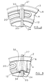
- the radiant heater shown in Figures 1 and 2 is arranged beneath a cooking surface 1, for example of glass ceramic material, and comprises a metal dish 2 containing a base layer 4 of electrical and thermal insulating material. Against the side of the dish 2 is located a peripheral wall 6 of thermal insulating material. The area within the peripheral wall 6 is divided into a first or inner, generally circular heating zone 8 and a second or outer, annular heating zone 10 by means of a circular wall 12 of thermal insulating material. Extending over the inner heating zone 8 and over at least a part of the outer heating zone 10 is a thermal cut-out device 14 for protecting the cooking surface against excessive temperatures. The thermal cut-out device will be explained in more detail hereinafter.
- Element 16 is in the form of a coil of bare resistance wire located in a groove formed in the base layer 4 and arranged within an infra-red lamp 18 of generally circular configuration.
- the lamp 18 is positioned within, but generally not in contact with, a recess formed in the base layer 4. Where the lamp 18 passes across the outer heating zone 10, the envelope of the lamp 18 is coated with a substantially opaque material in order to confine any visible light emitted by the lamp 18 to the inner heating zone 8.
- Element 20 is in the form of a coil of bare resistance wire located in a groove formed in the base layer 4 and is generally in the form of two concentric arcs, the inner arc extending substantially around the circumference of the outer heating zone and the outer arc extending substantially around 300 degrees of the outer heating zone.
- Element 22 is also in the form of a coil of bare resistance wire located in a groove formed in the base layer 4 and is generally in the form of an arc extending substantially around 60 degrees of the outer heating zone in that portion not occupied by the heating element 20.
- the thermal cut-out device 14 comprises a differential expansion probe-type temperature sensor 24 comprising a rod 25 of material having a high coefficient of thermal expansion, such as an iron-chrome alloy, arranged within a tube 27 of material having a low coefficient of thermal expansion, such as quartz, and a switch assembly 26 operable by the sensor 24.
- the sensor is configured in such a way that it is sensitive substantially only to heat emitted by the heating elements 16 and 18 in the inner heating zone 8 and is isolated from any heat emitted by the heating elements 20 and 22 in the outer heating zone 10.
- Isolation of the temperature sensor 24 can be achieved in a number of ways.
- the effective length of the temperature sensor 24 can be designed to terminate substantially at the boundary between the inner and outer heating zones, for example by substituting for the low expansion tube 27 in the outer heating zone a high expansion tube 36, for example made of the same material as that of the high expansion rod 25.
- the temperature sensor can be isolated by enclosing that part of the sensor passing through the outer heating zone 10 in a block 28 of thermal insulating material.
- the temperature sensor can be isolated by enclosing that part of the sensor passing through the outer heating zone 10 in a heat conducting material, such as a copper tube 30, such that the copper tube acts as a heat sink and heat absorbed is conducted outside the radiant heater.
- a heat conducting material such as a copper tube 30, such that the copper tube acts as a heat sink and heat absorbed is conducted outside the radiant heater.
- the temperature sensor can be isolated by extending the thermal influence of heat emitted in the inner heating zone to that part of the sensor passing through the outer heating zone 10, for example by providing a block 32 of thermal insulating material having a tapering tunnel 34 formed therein and communicating with the inner heating zone. It will be noted, however, that some minor alteration to the configuration of the heating element 20 may be required.
- the temperature sensor 24 is isolated from heat emitted by the heating elements 20 and 22 in the outer heating zone 10, it is necessary only to provide a single set of switch contacts in the switch assembly 26.
- the use of a thermal cut-out device 14 having only a single set of switch contacts in the switch assembly 26 results in a device which is more economical to manufacture compared with a thermal cut-out device such as that described in EP-A-0 103 741 which requires a switch assembly with an additional changeover switch for switching power to the heating elements.
- a second set of make-and-break contacts is available, as in Figure 1, these can have a lower power capacity and can be employed to switch at a considerably lower temperature, for example 60 °C, to give an indication to the user that the cooking surface 1 may be too hot to touch.
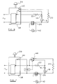
- the radiant heater is incorporated in a circuit such as that shown in Figure 6.
- Figure 6 shows that electrical energy is supplied to the radiant heater by way of an energy regulator 38 having a manually adjustable control knob 39 which determines the mark-to-space ratio of the switched output from the regulator.
- the energy regulator also incorporates a manually operable changeover switch 40 for switching between a first heating state in which only the heating elements 16 and 18 in the inner heating zone 8 are energised, for example for heating a relatively small cooking utensil, and a second heating state in which all the heating elements 16, 18, 20 and 22 are energised, for example for heating a relatively large cooking utensil.
- the heating elements 16 and 18 in the inner heating zone 8 In the first heating state as illustrated, in which only the heating elements 16 and 18 in the inner heating zone 8 are energised, electrical power passes through the switch 40 to the heating elements 16 and 18 which are electrically connected in series.
- the heating elements 16 and 18 are electrically connected in series because the lamp 18 has a very low electrical resistance at low temperatures and thus draws a very high starting current. It is often desirable to limit the starting current by incorporating a conventional heating coil in series with the lamp.
- the combined heating power of the heating elements 16 and 18 is typically 1200 watts giving a specific surface loading of some 0.073 watts/mm2.
- the temperature in the inner heating zone 8 is monitored by the temperature sensor 24 of the thermal cut-out device 14.
- the first set of contacts in the snap switch assembly 26 When the temperature detected exceeds a first predetermined temperature the first set of contacts in the snap switch assembly 26 is actuated to energise a warning light 42, and when the temperature detected exceeds a second predetermined temperature the second set of contacts in the snap switch assembly 26 is actuated to cut off power to both the heating elements 16 and 18.
- heating element 20 In the second heating state, in which the heating elements 20 and 22 in the outer heating zone 10 are energised in addition to the heating elements 16 and 18 in the inner heating zone, electrical power passes through the switch 40 to the heating element 20 and electrical power passes directly to heating elements 22, 16 and 18 which are electrically connected in series.
- the heating element 20 is connected in parallel with the series connected elements 22, 16 and 18.
- Heating element 22 is designed to generate typically 117 watts of power in the outer heating zone 10 and to reduce the power generated in the inner heating zone 8 by the heating elements 16 and 18 to typically 1000 watts, giving a specific surface loading of some 0.061 watts/mm2.
- Heating element 20 is designed to generate typically 1083 watts in the outer heating zone 10, making the total heat generated in the outer heating zone 10 some 1200 watts.
- the specific surface loading in the outer heating zone 10 is some 0.076 watts/mm2, that is about 25 per cent above the specific surface loading for the inner heating zone 8.
- the temperature in the inner heating zone 8 is monitored by the temperature sensor 24 of the thermal cut-out device 14.
- the first set of contacts in the snap switch assembly 26 is actuated to energise a warning light 42, and when the temperature detected exceeds a second predetermined temperature the second set of contacts in the snap switch assembly 26 is actuated to cut off power to all the heating elements 16, 18, 20 and 22.
- the heat generated in the inner heating zone is reduced from 1200 watts to 1000 watts. This has the effect of modifying the specific surface loading of the inner heating zone and permits the heat distribution in the inner and outer heating zones to be optimised in each of the first and second heating states.
- the heater need not have a concentric circular configuration.
- Other configurations include an arrangement where the inner heating zone and the outer heating zone are not concentric or an arrangement where a circular zone is provided for the first heating zone and a second heating zone is provided in the form of an additional zone on one or opposite sides of the circular zone so as to form a generally oval or rectangular heater.
- the invention has been described with two heating elements 16 and 18 in the first heating zone this is not necessary and the first heating zone may alternatively be provided with a single coil of bare resistance wire or a single infra-red lamp. Moreover, the invention has been described with a single heating element 20 generating the major part of the power in the second heating zone, but this may alternatively comprise an infra-red lamp or a coil of bare resistance wire in series with an infra-red lamp.
- the major benefit of the radiant heater according to the present invention is that the specific surface loading of the first heating zone is capable of being modified with a thermal cut-out device having a snap switch assembly with only a single set of contacts. This permits the heater to give improved performance over existing heaters that employ thermal cut-out devices having a snap switch assembly with only a single set of contacts.
- the invention also permits the heater either to be manufactured more economically than known radiant heaters that are able to modify the specific surface loading of one of the heating zones or to be more versatile in providing the well known facility for indicating to the user that the cooking surface may be too hot to touch.
Abstract
Description
- The present invention relates to a radiant heater having multiple heating zones which may be used, for example, in a cooking appliance having a glass ceramic cooking plate.
- Radiant heaters having multiple heating zones are known for example from GB-A-2 069 300 and EP-A-0 103 741. EP-A-0 103 741 describes a heater having inner and outer concentric heating zones, the inner heating zone containing one heating element and the outer heating zone containing two heating elements. A temperature sensor of a thermal cut-out device extends over both the inner and outer heating zones and is sensitive to heat emitted in both zones. The thermal cut-out device has two switches operating at upper and lower cut-out temperatures in order to protect the glass ceramic cooking surface against overheating.
- When the inner heating element is used alone, for example to heat a small cooking utensil, the inner heating element is operated at full power. In this condition, the inner heating element is connected to the thermal cut-out device by way of its switch operable at the lower cut-out temperature.
- When both the inner and outer heating zones are to be used together, for example to heat a large cooking utensil, one of the heating elements in the outer zone is electrically connected in series with the heating element in the inner zone, and the two heating elements in series are connected in parallel with the other heating element in the outer zone. In this condition, the heating elements are connected to the thermal cut-out device by way of its switch operable at the upper cut-out temperature. The effect of this is to reduce the specific heating surface loading in the inner zone as compared with the outer zone.
- This arrangement has the disadvantage that two switches on the thermal cut-out device are required to control the operation of the heating elements, one of the switches being a changeover switch rather than a simple make-and-break switch. This precludes the possibility of using the second switch on the thermal cut-out device as a signal switch, for example to warn the user of the cooking appliance that the glass ceramic cooking surface is at an elevated temperature and may be too hot to touch.
- It is an object of the present invention to provide a radiant heater having multiple heating zones in which it is possible to modify the specific heating surface loading of one of the heating zones in a manner which only uses a single switch of the thermal cut-out device.
- According to the present invention there is provided a radiant heater having multiple heating zones comprising:
a first heating zone provided with at least one heating element;
a second heating zone provided with at least first and second heating elements;
a thermal cut-out device including a temperature sensor passing through at least the first heating zone and responsive solely to heat emitted in the first heating zone; and
switch means for switching between first and second heating states, the arrangement being such that in the first heating state the at least one heating element in the first heating zone is energised alone and that in the second heating state the at least one heating element in the first heating zone is electrically connected in series with the second heating element of the second heating zone, the at least one heating element and the second heating element being energised in parallel with the first heating element of the second heating zone. - The heating element in the first heating zone may be a coil of bare resistance wire, an infra-red lamp, or a coil of bare resistance wire electrically connected in series with an infra-red lamp.
- The first heating element of the second heating zone may be a coil of bare resistance wire, an infra-red lamp, or a coil of bare resistance wire electrically connected in series with an infra-red lamp.
- The second heating element of the second heating zone may be a coil of bare resistance wire.
- The temperature sensor may pass through the second heating zone in a manner which renders the sensor substantially unresponsive to heat emitted in the second heating zone. For example, the temperature sensor may comprise a differential expansion member, the differential expansion of the sensor being substantially eliminated in that region of the sensor passing through the second heating zone. Alternatively, that region of the temperature sensor passing through the second heating zone may be isolated from heat emitted in the second heating zone by means of a block of thermal insulating material at least partly surrounding the sensor. As a further alternative, that region of the temperature sensor passing through the second heating zone may be at least partly surrounded by a thermally conducting element arranged to conduct heat externally of the heater. According to another alternative, that region of the temperature sensor passing through the second heating zone may be isolated from heat emitted in the second heating zone and exposed to heat emitted in the first heating zone.
- The first and second heating zones may be separated by a wall of thermal insulating material.
- The first heating zone may be circular and the second heating zone may be annular, the second heating zone surrounding the first heating zone.
- For a better understanding of the present invention and to show more clearly how it may be carried into effect reference will now be made, by way of example, to the accompanying drawings in which:
- Figure 1 is a plan view of one embodiment of a radiant heater according to the present invention;
- Figure 2 is a cross-sectional view taken along the line II-II in Figure 1;
- Figure 3a is an elevational view of another embodiment of a part of the radiant heater shown in Figures 1 and 2;
- Figure 3b is a plan view corresponding to Figure 3a;
- Figure 4 is a plan view of a further embodiment of part of the radiant heater shown in Figures 1 and 2;
- Figure 5 is a plan view of a yet another embodiment of part of the radiant heater shown in Figures 1 and 2;
- Figure 6 is a schematic circuit diagram illustrating one circuit for controlling the radiant heater of Figures 1 and 2; and
- Figure 7 is a schematic circuit diagram illustrating another circuit for controlling the radiant heater of Figures 1 and 2.
- The radiant heater shown in Figures 1 and 2 is arranged beneath a
cooking surface 1, for example of glass ceramic material, and comprises ametal dish 2 containing abase layer 4 of electrical and thermal insulating material. Against the side of thedish 2 is located aperipheral wall 6 of thermal insulating material. The area within theperipheral wall 6 is divided into a first or inner, generallycircular heating zone 8 and a second or outer,annular heating zone 10 by means of acircular wall 12 of thermal insulating material. Extending over theinner heating zone 8 and over at least a part of theouter heating zone 10 is a thermal cut-outdevice 14 for protecting the cooking surface against excessive temperatures. The thermal cut-out device will be explained in more detail hereinafter. - Within the
inner heating zone 8 are arranged twoheating elements Element 16 is in the form of a coil of bare resistance wire located in a groove formed in thebase layer 4 and arranged within an infra-red lamp 18 of generally circular configuration. Thelamp 18 is positioned within, but generally not in contact with, a recess formed in thebase layer 4. Where thelamp 18 passes across theouter heating zone 10, the envelope of thelamp 18 is coated with a substantially opaque material in order to confine any visible light emitted by thelamp 18 to theinner heating zone 8. - In the
outer heating zone 10 are arranged twoheating elements Element 20 is in the form of a coil of bare resistance wire located in a groove formed in thebase layer 4 and is generally in the form of two concentric arcs, the inner arc extending substantially around the circumference of the outer heating zone and the outer arc extending substantially around 300 degrees of the outer heating zone.Element 22 is also in the form of a coil of bare resistance wire located in a groove formed in thebase layer 4 and is generally in the form of an arc extending substantially around 60 degrees of the outer heating zone in that portion not occupied by theheating element 20. - The thermal cut-out
device 14 comprises a differential expansion probe-type temperature sensor 24 comprising arod 25 of material having a high coefficient of thermal expansion, such as an iron-chrome alloy, arranged within atube 27 of material having a low coefficient of thermal expansion, such as quartz, and aswitch assembly 26 operable by thesensor 24. The sensor is configured in such a way that it is sensitive substantially only to heat emitted by theheating elements inner heating zone 8 and is isolated from any heat emitted by theheating elements outer heating zone 10. - Isolation of the
temperature sensor 24 can be achieved in a number of ways. As shown in Figure 1, the effective length of thetemperature sensor 24 can be designed to terminate substantially at the boundary between the inner and outer heating zones, for example by substituting for thelow expansion tube 27 in the outer heating zone ahigh expansion tube 36, for example made of the same material as that of thehigh expansion rod 25. As shown in Figures 3a and 3b, the temperature sensor can be isolated by enclosing that part of the sensor passing through theouter heating zone 10 in ablock 28 of thermal insulating material. As shown in Figure 4, the temperature sensor can be isolated by enclosing that part of the sensor passing through theouter heating zone 10 in a heat conducting material, such as acopper tube 30, such that the copper tube acts as a heat sink and heat absorbed is conducted outside the radiant heater. As shown in Figure 5, the temperature sensor can be isolated by extending the thermal influence of heat emitted in the inner heating zone to that part of the sensor passing through theouter heating zone 10, for example by providing ablock 32 of thermal insulating material having atapering tunnel 34 formed therein and communicating with the inner heating zone. It will be noted, however, that some minor alteration to the configuration of theheating element 20 may be required. - Because the
temperature sensor 24 is isolated from heat emitted by theheating elements outer heating zone 10, it is necessary only to provide a single set of switch contacts in theswitch assembly 26. The use of a thermal cut-outdevice 14 having only a single set of switch contacts in theswitch assembly 26 results in a device which is more economical to manufacture compared with a thermal cut-out device such as that described in EP-A-0 103 741 which requires a switch assembly with an additional changeover switch for switching power to the heating elements. Where a second set of make-and-break contacts is available, as in Figure 1, these can have a lower power capacity and can be employed to switch at a considerably lower temperature, for example 60 °C, to give an indication to the user that thecooking surface 1 may be too hot to touch. - In use, the radiant heater is incorporated in a circuit such as that shown in Figure 6. Figure 6 shows that electrical energy is supplied to the radiant heater by way of an
energy regulator 38 having a manuallyadjustable control knob 39 which determines the mark-to-space ratio of the switched output from the regulator. The energy regulator also incorporates a manuallyoperable changeover switch 40 for switching between a first heating state in which only theheating elements inner heating zone 8 are energised, for example for heating a relatively small cooking utensil, and a second heating state in which all theheating elements - In the first heating state as illustrated, in which only the
heating elements inner heating zone 8 are energised, electrical power passes through theswitch 40 to theheating elements heating elements lamp 18 has a very low electrical resistance at low temperatures and thus draws a very high starting current. It is often desirable to limit the starting current by incorporating a conventional heating coil in series with the lamp. For aninner heating zone 8 having a diameter of some 145 mm the combined heating power of theheating elements inner heating zone 8 is monitored by thetemperature sensor 24 of the thermal cut-outdevice 14. When the temperature detected exceeds a first predetermined temperature the first set of contacts in thesnap switch assembly 26 is actuated to energise awarning light 42, and when the temperature detected exceeds a second predetermined temperature the second set of contacts in thesnap switch assembly 26 is actuated to cut off power to both theheating elements - In the second heating state, in which the
heating elements outer heating zone 10 are energised in addition to theheating elements switch 40 to theheating element 20 and electrical power passes directly toheating elements heating element 20 is connected in parallel with the series connectedelements Heating element 22 is designed to generate typically 117 watts of power in theouter heating zone 10 and to reduce the power generated in theinner heating zone 8 by theheating elements Heating element 20 is designed to generate typically 1083 watts in theouter heating zone 10, making the total heat generated in theouter heating zone 10 some 1200 watts. For a radiant heater having a diameter of some 210 mm, and an internal wall 5 mm thick where it is in contact with the underside of the glass ceramic cooking surface, the specific surface loading in theouter heating zone 10 is some 0.076 watts/mm², that is about 25 per cent above the specific surface loading for theinner heating zone 8. As with the first heating state, the temperature in theinner heating zone 8 is monitored by thetemperature sensor 24 of the thermal cut-outdevice 14. When the temperature detected exceeds a first predetermined temperature the first set of contacts in thesnap switch assembly 26 is actuated to energise awarning light 42, and when the temperature detected exceeds a second predetermined temperature the second set of contacts in thesnap switch assembly 26 is actuated to cut off power to all theheating elements - Use of the radiant heater in the circuit according to Figure 7 is similar to that of Figure 6, except that the
switch 44 in the energy regulator is a simple make-and-break switch rather than a more complex changeover switch. In order to use the radiant heater with theswitch 44 in the second heating state as illustrated, electrical power from theswitch 44 is connected across a relay coil 46 andrelay contacts 48 are employed as a substitute for theswitch 40. - Numerous modifications are possible to the radiant heater described above. For example, the heater need not have a concentric circular configuration. Other configurations include an arrangement where the inner heating zone and the outer heating zone are not concentric or an arrangement where a circular zone is provided for the first heating zone and a second heating zone is provided in the form of an additional zone on one or opposite sides of the circular zone so as to form a generally oval or rectangular heater.
- Although the invention has been described with two
heating elements single heating element 20 generating the major part of the power in the second heating zone, but this may alternatively comprise an infra-red lamp or a coil of bare resistance wire in series with an infra-red lamp. - The major benefit of the radiant heater according to the present invention is that the specific surface loading of the first heating zone is capable of being modified with a thermal cut-out device having a snap switch assembly with only a single set of contacts. This permits the heater to give improved performance over existing heaters that employ thermal cut-out devices having a snap switch assembly with only a single set of contacts. The invention also permits the heater either to be manufactured more economically than known radiant heaters that are able to modify the specific surface loading of one of the heating zones or to be more versatile in providing the well known facility for indicating to the user that the cooking surface may be too hot to touch.
Claims (11)
- A radiant heater having multiple heating zones comprising:
a first heating zone (8) provided with at least one heating element (16, 18);
a second heating zone (10) provided with at least first (20) and second (22) heating elements;
a thermal cut-out device (14) including a temperature sensor (24) passing through at least the first heating zone (8) and responsive solely to heat emitted in the first heating zone; and
switch means (40) for switching between first and second heating states, the arrangement being such that in the first heating state the at least one heating element (16, 18) in the first heating zone (8) is energised alone and that in the second heating state the at least one heating element (16, 18) in the first heating zone is electrically connected in series with the second heating element (22) of the second heating zone (10), the at least one heating element (16, 18) and the second heating element (22) being energised in parallel with the first heating element (20) of the second heating zone (10). - A radiant heater as claimed in claim 1, characterised in that the first heating zone (8) is provided with a heating element in the form of a coil of bare resistance wire (16), or in the form of an infra-red lamp (18), or in the form of a coil of bare resistance wire (16) electrically connected in series with an infra-red lamp (18).
- A radiant heater as claimed in claim 1 or 2, characterised in that the first heating element (20) of the second heating zone (10) comprises a coil of bare resistance wire or an infra-red lamp or a coil of bare resistance wire electrically connected in series with an infra-red lamp.
- A radiant heater as claimed in any preceding claim, characterised in that the second heating element (22) of the second heating zone (10) comprises a coil of bare resistance wire.
- A radiant heater as claimed in any preceding claim, characterised in that the temperature sensor (24) passes through the second heating zone (10) in a manner which renders the sensor substantially unresponsive to heat emitted in the second heating zone.
- A radiant heater as claimed in claim 5, characterised in that the temperature sensor (24) comprises a differential expansion member, the differential expansion of the sensor being substantially eliminated in that region of the sensor passing through the second heating zone (10).
- A radiant heater as claimed in claim 5, characterised in that that region of the temperature sensor (24) passing through the second heating zone (10) is isolated from heat emitted in the second heating zone by means of a block (28) of thermal insulating material at least partly surrounding the sensor.
- A radiant heater as claimed in claim 5, characterised in that that region of the temperature sensor (24) passing through the second heating zone (10) is at least partly surrounded by a thermally conducting element (30) arranged to conduct heat externally of the heater.
- A radiant heater as claimed in claim 5, characterised in that that region of the temperature sensor (24) passing through the second heating zone (10) is isolated from heat emitted in the second heating zone and exposed to heat emitted in the first heating zone.
- A radiant heater as claimed in any preceding claim, characterised in that the first and second heating zones are separated by a wall (12) of thermal insulating material.
- A radiant heater as claimed in any preceding claim, characterised in that the first heating zone (8) is circular and the second heating zone (10) is annular, the second heating zone surrounding the first heating zone.
Applications Claiming Priority (2)
| Application Number | Priority Date | Filing Date | Title |
|---|---|---|---|
| GB9200532A GB2263379B (en) | 1992-01-10 | 1992-01-10 | Radiant heater having multiple heating zones |
| GB9200532 | 1992-01-10 |
Publications (3)
| Publication Number | Publication Date |
|---|---|
| EP0551172A2 true EP0551172A2 (en) | 1993-07-14 |
| EP0551172A3 EP0551172A3 (en) | 1993-10-13 |
| EP0551172B1 EP0551172B1 (en) | 1998-09-02 |
Family
ID=10708422
Family Applications (1)
| Application Number | Title | Priority Date | Filing Date |
|---|---|---|---|
| EP93300022A Expired - Lifetime EP0551172B1 (en) | 1992-01-10 | 1993-01-04 | Radiant heater having multiple heating zones |
Country Status (8)
| Country | Link |
|---|---|
| US (1) | US5270519A (en) |
| EP (1) | EP0551172B1 (en) |
| JP (1) | JPH05264043A (en) |
| AT (1) | ATE170700T1 (en) |
| CA (1) | CA2086861C (en) |
| DE (1) | DE69320667T2 (en) |
| ES (1) | ES2120476T3 (en) |
| GB (1) | GB2263379B (en) |
Cited By (7)
| Publication number | Priority date | Publication date | Assignee | Title |
|---|---|---|---|---|
| GB2307363A (en) * | 1995-11-15 | 1997-05-21 | Ceramaspeed Ltd | Heater for a glass ceramic top cooking appliance |
| GB2333406A (en) * | 1998-01-16 | 1999-07-21 | Ceramaspeed Ltd | Radiant electric heater; glass-ceramic top cooking appliance |
| EP1003352A2 (en) * | 1998-11-20 | 2000-05-24 | E.G.O. Elektro-Gerätebau GmbH | Radiant electric heaters and its manufacturing process |
| DE10018816A1 (en) * | 2000-04-15 | 2001-10-31 | Ego Elektro Geraetebau Gmbh | Radiant heater, especially for a glass ceramic cooktop |
| WO2003003793A1 (en) * | 2001-06-28 | 2003-01-09 | Ceramaspeed Limited | Cooking appliance |
| EP1448024A2 (en) * | 2003-02-17 | 2004-08-18 | E.G.O. ELEKTRO-GERÄTEBAU GmbH | Heating device with two areas |
| WO2006045705A1 (en) * | 2004-10-29 | 2006-05-04 | BSH Bosch und Siemens Hausgeräte GmbH | Hob comprising a temperature sensor |
Families Citing this family (33)
| Publication number | Priority date | Publication date | Assignee | Title |
|---|---|---|---|---|
| DE4022846C2 (en) * | 1990-07-18 | 1994-08-11 | Schott Glaswerke | Device for power control and limitation in a heating surface made of glass ceramic or a comparable material |
| DE4130337C2 (en) * | 1991-09-12 | 2002-05-02 | Ego Elektro Blanc & Fischer | Method for operating an electric heating unit and electric heating unit |
| GB2287388B (en) * | 1994-03-09 | 1997-07-16 | Ceramaspeed Ltd | Radiant electric heater |
| EP0720125B1 (en) * | 1994-12-29 | 2002-05-08 | Koninklijke Philips Electronics N.V. | Image forming apparatus and method for correcting optical geometrical distortions in an image |
| GB2307836B (en) * | 1995-11-30 | 2000-05-24 | Ceramaspeed Ltd | Radiant electric heater arrangement |
| DE19604306C2 (en) * | 1996-02-07 | 2000-05-11 | Ako Werke Gmbh & Co | Radiant heater |
| GB2335834B (en) * | 1998-03-26 | 2002-10-23 | Ceramaspeed Ltd | Radiant electric heater |
| US5973298A (en) * | 1998-04-27 | 1999-10-26 | White Consolidated Industries, Inc. | Circular film heater and porcelain enamel cooktop |
| GB2336985A (en) * | 1998-04-30 | 1999-11-03 | Ceramaspeed Ltd | A radiant electric heater having both a lamp-form heating element and a ribbon heating element |
| GB2340715B (en) * | 1998-08-14 | 2003-01-29 | Ceramaspeed Ltd | Radiant electric heater |
| US6225608B1 (en) | 1999-11-30 | 2001-05-01 | White Consolidated Industries, Inc. | Circular film heater |
| GB2360683B (en) * | 2000-03-23 | 2004-11-10 | Ceramaspeed Ltd | Radiant electric heater |
| US7153286B2 (en) | 2002-05-24 | 2006-12-26 | Baxter International Inc. | Automated dialysis system |
| US20040178190A1 (en) * | 2002-12-11 | 2004-09-16 | Brad Bivens | Non-uniform wattage density heater |
| ES1057791Y (en) * | 2004-06-14 | 2005-01-01 | Eika S Coop | RADIANT HEATER IN A COOKING HOB, WITH A THERMAL SWITCH. |
| WO2007044646A2 (en) * | 2005-10-05 | 2007-04-19 | Evo, Inc. | Electric cooking apparatus |
| US20080142505A1 (en) * | 2006-12-18 | 2008-06-19 | Bsh Home Appliances Corporation | Low simmer heating element with mechanical switches |
| US8027572B2 (en) | 2008-02-22 | 2011-09-27 | Baxter International Inc. | Dialysis machine having multiple line voltage heater |
| US9435459B2 (en) | 2009-06-05 | 2016-09-06 | Baxter International Inc. | Solenoid pinch valve apparatus and method for medical fluid applications having reduced noise production |
| SI2440094T1 (en) | 2009-06-12 | 2017-05-31 | Burger King Corporation | Electric broiler |
| WO2010151839A1 (en) | 2009-06-26 | 2010-12-29 | Evo, Inc. | Electric cooking apparatus |
| WO2011056569A1 (en) * | 2009-10-28 | 2011-05-12 | The Dow Chemical Investments Llc | Device to dry catalyst roaster conveyor belt and method of using same |
| US8884195B2 (en) * | 2011-12-09 | 2014-11-11 | E.G.O. Elektro-Gerätebau GmbH | Heating device, method of producing a heating device and method for operating a heating device |
| US8933377B2 (en) | 2011-12-09 | 2015-01-13 | E.G.O. Elektro-Gerätebau GmbH | Control device for an electrical heating device for a cooking field, cooking field and method for operating such an electrical heating device |
| US9696091B2 (en) | 2012-07-13 | 2017-07-04 | Adc Acquisition Company | Superimposed zones process heating |
| US10132504B1 (en) | 2017-05-15 | 2018-11-20 | Backer Ehp Inc. | Dual coil electric heating element |
| US11067288B2 (en) | 2017-05-15 | 2021-07-20 | Backer Ehp Inc. | Dual coil electric heating element |
| US11125441B2 (en) * | 2017-12-01 | 2021-09-21 | Transform Sr Brands Llc | Heating device |
| CN108652424A (en) * | 2018-06-13 | 2018-10-16 | 李金胜 | A kind of electric food warmer heating system |
| KR102093766B1 (en) * | 2018-08-21 | 2020-03-26 | 엘지전자 주식회사 | Electric Heater |
| USD955168S1 (en) | 2019-07-03 | 2022-06-21 | Backer Ehp Inc. | Electric heating element |
| US11581156B2 (en) | 2019-07-03 | 2023-02-14 | Backer Ehp Inc. | Dual coil electric heating element |
| US11570853B2 (en) * | 2021-02-01 | 2023-01-31 | E.G.O. Elektro-Geraetebau Gmbh | Method for actuating a heating device of a hob, and hob |
Citations (4)
| Publication number | Priority date | Publication date | Assignee | Title |
|---|---|---|---|---|
| GB2186166A (en) * | 1986-01-24 | 1987-08-05 | Redring Electric Ltd | Electric hobs and heating units therefor |
| DE3737475A1 (en) * | 1987-11-05 | 1989-05-18 | Ego Elektro Blanc & Fischer | Radiant heating element for cooking appliances |
| EP0331369A1 (en) * | 1988-02-26 | 1989-09-06 | Electrolux Limited | Controllable electric heater |
| DE9107618U1 (en) * | 1990-06-23 | 1991-08-22 | Ceramaspeed Ltd., Droitwich, Worcestershire, Gb |
Family Cites Families (14)
| Publication number | Priority date | Publication date | Assignee | Title |
|---|---|---|---|---|
| GB816962A (en) * | 1956-08-20 | 1959-07-22 | Robert Maclaren & Company Ltd | An improved control arrangement for electric hot plates and other electric heating appliances |
| US1436657A (en) * | 1921-11-26 | 1922-11-28 | Clarence B Ingersoll | Electrical heating device |
| CH193572A (en) * | 1937-01-21 | 1937-10-31 | Salvis A G | Electric hotplate. |
| US2291857A (en) * | 1939-11-21 | 1942-08-04 | Westinghouse Electric & Mfg Co | Cooking appliance |
| US2419083A (en) * | 1943-01-12 | 1947-04-15 | Proctor Electric Co | Electrical cooking apparatus |
| DE1097586B (en) * | 1954-11-30 | 1961-01-19 | Karl Fischer | Hot plate with multi-stage switch |
| CH559337A5 (en) * | 1972-08-02 | 1975-02-28 | Siemens Elektrogeraete Gmbh | Power regulator for an electrically heated cooking plate - had divided resistance heating elements and an overheating protection switch |
| SE8000898L (en) * | 1979-02-07 | 1980-08-08 | Micropore International Ltd | DEVICE FOR DELETING COOKERS |
| GB2069300B (en) * | 1980-02-01 | 1983-09-01 | Mictropore International Ltd | Radiant heating elements for smooth top cookers |
| GB2080660B (en) * | 1980-07-22 | 1983-10-12 | Micropore International Ltd | Electric radiant unit for a glass ceramic top cooker |
| DE3315438A1 (en) * | 1983-04-28 | 1984-10-31 | E.G.O. Elektro-Geräte Blanc u. Fischer, 7519 Oberderdingen | HEATING ELEMENT FOR HEATING COOKING, HEATING PLATES OR THE LIKE |
| GB8327872D0 (en) * | 1983-10-18 | 1983-11-16 | Thorn Emi Domestic Appliances | Heating apparatus |
| GB8412339D0 (en) * | 1984-05-15 | 1984-06-20 | Thorn Emi Domestic Appliances | Heating apparatus |
| DE3623130A1 (en) * | 1986-07-09 | 1988-01-21 | Ako Werke Gmbh & Co | RADIATION HEATING |
-
1992
- 1992-01-10 GB GB9200532A patent/GB2263379B/en not_active Expired - Fee Related
-
1993
- 1993-01-04 EP EP93300022A patent/EP0551172B1/en not_active Expired - Lifetime
- 1993-01-04 DE DE69320667T patent/DE69320667T2/en not_active Expired - Fee Related
- 1993-01-04 AT AT93300022T patent/ATE170700T1/en not_active IP Right Cessation
- 1993-01-04 ES ES93300022T patent/ES2120476T3/en not_active Expired - Lifetime
- 1993-01-05 US US08/000,889 patent/US5270519A/en not_active Expired - Fee Related
- 1993-01-07 CA CA002086861A patent/CA2086861C/en not_active Expired - Fee Related
- 1993-01-08 JP JP5016823A patent/JPH05264043A/en not_active Withdrawn
Patent Citations (4)
| Publication number | Priority date | Publication date | Assignee | Title |
|---|---|---|---|---|
| GB2186166A (en) * | 1986-01-24 | 1987-08-05 | Redring Electric Ltd | Electric hobs and heating units therefor |
| DE3737475A1 (en) * | 1987-11-05 | 1989-05-18 | Ego Elektro Blanc & Fischer | Radiant heating element for cooking appliances |
| EP0331369A1 (en) * | 1988-02-26 | 1989-09-06 | Electrolux Limited | Controllable electric heater |
| DE9107618U1 (en) * | 1990-06-23 | 1991-08-22 | Ceramaspeed Ltd., Droitwich, Worcestershire, Gb |
Cited By (17)
| Publication number | Priority date | Publication date | Assignee | Title |
|---|---|---|---|---|
| GB2307363A (en) * | 1995-11-15 | 1997-05-21 | Ceramaspeed Ltd | Heater for a glass ceramic top cooking appliance |
| EP0774881A3 (en) * | 1995-11-15 | 1997-12-10 | Ceramaspeed Limited | Infra-red heater arrangement |
| US5866879A (en) * | 1995-11-15 | 1999-02-02 | Ceramaspeed Limited | Infra-red heater arrangement |
| GB2307363B (en) * | 1995-11-15 | 2000-01-19 | Ceramaspeed Ltd | Infra-red heater arrangement |
| GB2333406A (en) * | 1998-01-16 | 1999-07-21 | Ceramaspeed Ltd | Radiant electric heater; glass-ceramic top cooking appliance |
| US6018149A (en) * | 1998-01-16 | 2000-01-25 | Ceramaspeed Limited | Radiant electric heater |
| GB2333406B (en) * | 1998-01-16 | 2001-10-10 | Ceramaspeed Ltd | Radiant electric heater |
| EP1003352A3 (en) * | 1998-11-20 | 2001-03-14 | E.G.O. Elektro-Gerätebau GmbH | Radiant electric heaters and its manufacturing process |
| DE19853542A1 (en) * | 1998-11-20 | 2000-05-25 | Ego Elektro Geraetebau Gmbh | Radiant heater and process for its manufacture |
| EP1003352A2 (en) * | 1998-11-20 | 2000-05-24 | E.G.O. Elektro-Gerätebau GmbH | Radiant electric heaters and its manufacturing process |
| DE10018816A1 (en) * | 2000-04-15 | 2001-10-31 | Ego Elektro Geraetebau Gmbh | Radiant heater, especially for a glass ceramic cooktop |
| WO2003003793A1 (en) * | 2001-06-28 | 2003-01-09 | Ceramaspeed Limited | Cooking appliance |
| US6995344B2 (en) | 2001-06-28 | 2006-02-07 | Ceramaspeed Limited | Cooking appliance |
| EP1448024A2 (en) * | 2003-02-17 | 2004-08-18 | E.G.O. ELEKTRO-GERÄTEBAU GmbH | Heating device with two areas |
| EP1448024A3 (en) * | 2003-02-17 | 2005-10-19 | E.G.O. ELEKTRO-GERÄTEBAU GmbH | Heating device with two areas |
| WO2006045705A1 (en) * | 2004-10-29 | 2006-05-04 | BSH Bosch und Siemens Hausgeräte GmbH | Hob comprising a temperature sensor |
| DE102004053012B4 (en) | 2004-10-29 | 2023-01-12 | BSH Hausgeräte GmbH | Hob with a temperature sensor |
Also Published As
| Publication number | Publication date |
|---|---|
| DE69320667T2 (en) | 1999-03-25 |
| CA2086861A1 (en) | 1993-07-11 |
| CA2086861C (en) | 2002-04-16 |
| DE69320667D1 (en) | 1998-10-08 |
| EP0551172B1 (en) | 1998-09-02 |
| JPH05264043A (en) | 1993-10-12 |
| GB9200532D0 (en) | 1992-02-26 |
| EP0551172A3 (en) | 1993-10-13 |
| GB2263379A (en) | 1993-07-21 |
| ATE170700T1 (en) | 1998-09-15 |
| GB2263379B (en) | 1995-07-26 |
| ES2120476T3 (en) | 1998-11-01 |
| US5270519A (en) | 1993-12-14 |
Similar Documents
| Publication | Publication Date | Title |
|---|---|---|
| US5270519A (en) | Radiant heater having multiple heating zones | |
| US4789772A (en) | Infra-red heaters | |
| EP0481162B1 (en) | Domestic cooking apparatus | |
| US3612826A (en) | Surface temperature indicator light for ceramic top infrared radiant range | |
| US4388520A (en) | Electric cookers with warning lights | |
| US4447710A (en) | Electric cookers incorporating radiant heaters | |
| US4430558A (en) | Electric radiant heater unit for a glass ceramic top cooker | |
| US5220155A (en) | Heating and sensing apparatus for range top | |
| US20020011480A1 (en) | Temperature detection device for an electric radiant heater | |
| EP0943870B1 (en) | Temperature sensing and limiting device | |
| EP1488666B1 (en) | Electrical heating assembly | |
| EP1400151B1 (en) | Cooking appliance | |
| GB2103910A (en) | Improvements in electric cookers incorporating radiant heaters | |
| GB2138659A (en) | Glass Ceramic Hob including Temperature Sensor | |
| EP0174774A1 (en) | Heating apparatus | |
| US20030178405A1 (en) | Electrical heating assembly | |
| EP0774881A2 (en) | Infra-red heater arrangement | |
| GB2067880A (en) | Glass Ceramic Hob Including Temperature Sensor | |
| GB2225920A (en) | Controlling an electric heater unit for an electric ceramic hob | |
| GB2218605A (en) | Control means for an electric heater unit for an electric ceramic hob | |
| GB2186167A (en) | Electric hobs | |
| GB2116010A (en) | Elastic radiant heater units for use in glass ceramic top cookers |
Legal Events
| Date | Code | Title | Description |
|---|---|---|---|
| PUAI | Public reference made under article 153(3) epc to a published international application that has entered the european phase |
Free format text: ORIGINAL CODE: 0009012 |
|
| AK | Designated contracting states |
Kind code of ref document: A2 Designated state(s): AT BE CH DE DK ES FR GB GR IT LI NL PT SE |
|
| PUAL | Search report despatched |
Free format text: ORIGINAL CODE: 0009013 |
|
| AK | Designated contracting states |
Kind code of ref document: A3 Designated state(s): AT BE CH DE DK ES FR GB GR IT LI NL PT SE |
|
| 17P | Request for examination filed |
Effective date: 19931108 |
|
| 17Q | First examination report despatched |
Effective date: 19951222 |
|
| GRAG | Despatch of communication of intention to grant |
Free format text: ORIGINAL CODE: EPIDOS AGRA |
|
| GRAG | Despatch of communication of intention to grant |
Free format text: ORIGINAL CODE: EPIDOS AGRA |
|
| GRAH | Despatch of communication of intention to grant a patent |
Free format text: ORIGINAL CODE: EPIDOS IGRA |
|
| GRAH | Despatch of communication of intention to grant a patent |
Free format text: ORIGINAL CODE: EPIDOS IGRA |
|
| RBV | Designated contracting states (corrected) |
Designated state(s): AT BE CH DE DK ES FR GR IT LI NL PT SE |
|
| GRAA | (expected) grant |
Free format text: ORIGINAL CODE: 0009210 |
|
| AK | Designated contracting states |
Kind code of ref document: B1 Designated state(s): AT BE CH DE DK ES FR GR IT LI NL PT SE |
|
| PG25 | Lapsed in a contracting state [announced via postgrant information from national office to epo] |
Ref country code: NL Free format text: LAPSE BECAUSE OF FAILURE TO SUBMIT A TRANSLATION OF THE DESCRIPTION OR TO PAY THE FEE WITHIN THE PRESCRIBED TIME-LIMIT Effective date: 19980902 Ref country code: LI Free format text: LAPSE BECAUSE OF FAILURE TO SUBMIT A TRANSLATION OF THE DESCRIPTION OR TO PAY THE FEE WITHIN THE PRESCRIBED TIME-LIMIT Effective date: 19980902 Ref country code: GR Free format text: LAPSE BECAUSE OF NON-PAYMENT OF DUE FEES Effective date: 19980902 Ref country code: CH Free format text: LAPSE BECAUSE OF FAILURE TO SUBMIT A TRANSLATION OF THE DESCRIPTION OR TO PAY THE FEE WITHIN THE PRESCRIBED TIME-LIMIT Effective date: 19980902 Ref country code: BE Free format text: LAPSE BECAUSE OF FAILURE TO SUBMIT A TRANSLATION OF THE DESCRIPTION OR TO PAY THE FEE WITHIN THE PRESCRIBED TIME-LIMIT Effective date: 19980902 Ref country code: AT Free format text: LAPSE BECAUSE OF FAILURE TO SUBMIT A TRANSLATION OF THE DESCRIPTION OR TO PAY THE FEE WITHIN THE PRESCRIBED TIME-LIMIT Effective date: 19980902 |
|
| REF | Corresponds to: |
Ref document number: 170700 Country of ref document: AT Date of ref document: 19980915 Kind code of ref document: T |
|
| REG | Reference to a national code |
Ref country code: CH Ref legal event code: EP |
|
| REF | Corresponds to: |
Ref document number: 69320667 Country of ref document: DE Date of ref document: 19981008 |
|
| REG | Reference to a national code |
Ref country code: ES Ref legal event code: FG2A Ref document number: 2120476 Country of ref document: ES Kind code of ref document: T3 |
|
| ET | Fr: translation filed | ||
| PG25 | Lapsed in a contracting state [announced via postgrant information from national office to epo] |
Ref country code: SE Free format text: LAPSE BECAUSE OF FAILURE TO SUBMIT A TRANSLATION OF THE DESCRIPTION OR TO PAY THE FEE WITHIN THE PRESCRIBED TIME-LIMIT Effective date: 19981202 Ref country code: PT Free format text: LAPSE BECAUSE OF FAILURE TO SUBMIT A TRANSLATION OF THE DESCRIPTION OR TO PAY THE FEE WITHIN THE PRESCRIBED TIME-LIMIT Effective date: 19981202 Ref country code: DK Free format text: LAPSE BECAUSE OF FAILURE TO SUBMIT A TRANSLATION OF THE DESCRIPTION OR TO PAY THE FEE WITHIN THE PRESCRIBED TIME-LIMIT Effective date: 19981202 |
|
| NLV1 | Nl: lapsed or annulled due to failure to fulfill the requirements of art. 29p and 29m of the patents act | ||
| REG | Reference to a national code |
Ref country code: CH Ref legal event code: PL |
|
| PLAV | Examination of admissibility of opposition |
Free format text: ORIGINAL CODE: EPIDOS OPEX |
|
| PLBI | Opposition filed |
Free format text: ORIGINAL CODE: 0009260 |
|
| PLBQ | Unpublished change to opponent data |
Free format text: ORIGINAL CODE: EPIDOS OPPO |
|
| PLAB | Opposition data, opponent's data or that of the opponent's representative modified |
Free format text: ORIGINAL CODE: 0009299OPPO |
|
| PLBF | Reply of patent proprietor to notice(s) of opposition |
Free format text: ORIGINAL CODE: EPIDOS OBSO |
|
| 26 | Opposition filed |
Opponent name: DIEHL STIFTUNG & CO. Effective date: 19990531 |
|
| R26 | Opposition filed (corrected) |
Opponent name: DIEHL STIFTUNG & CO. Effective date: 19990531 |
|
| PLBF | Reply of patent proprietor to notice(s) of opposition |
Free format text: ORIGINAL CODE: EPIDOS OBSO |
|
| PLBO | Opposition rejected |
Free format text: ORIGINAL CODE: EPIDOS REJO |
|
| PLBN | Opposition rejected |
Free format text: ORIGINAL CODE: 0009273 |
|
| 27O | Opposition rejected |
Effective date: 20020426 |
|
| PGFP | Annual fee paid to national office [announced via postgrant information from national office to epo] |
Ref country code: ES Payment date: 20041203 Year of fee payment: 13 |
|
| PG25 | Lapsed in a contracting state [announced via postgrant information from national office to epo] |
Ref country code: IT Free format text: LAPSE BECAUSE OF NON-PAYMENT OF DUE FEES Effective date: 20050104 |
|
| PGFP | Annual fee paid to national office [announced via postgrant information from national office to epo] |
Ref country code: DE Payment date: 20050113 Year of fee payment: 13 |
|
| PGFP | Annual fee paid to national office [announced via postgrant information from national office to epo] |
Ref country code: FR Payment date: 20050127 Year of fee payment: 13 |
|
| PG25 | Lapsed in a contracting state [announced via postgrant information from national office to epo] |
Ref country code: ES Free format text: LAPSE BECAUSE OF NON-PAYMENT OF DUE FEES Effective date: 20060105 |
|
| PG25 | Lapsed in a contracting state [announced via postgrant information from national office to epo] |
Ref country code: FR Free format text: LAPSE BECAUSE OF NON-PAYMENT OF DUE FEES Effective date: 20060131 |
|
| PG25 | Lapsed in a contracting state [announced via postgrant information from national office to epo] |
Ref country code: DE Free format text: LAPSE BECAUSE OF NON-PAYMENT OF DUE FEES Effective date: 20060801 |
|
| REG | Reference to a national code |
Ref country code: FR Ref legal event code: ST Effective date: 20060929 |
|
| REG | Reference to a national code |
Ref country code: ES Ref legal event code: FD2A Effective date: 20060105 |
|
| PLAE | Information related to rejection of opposition modified |
Free format text: ORIGINAL CODE: 0009299REJO |
|
| STAA | Information on the status of an ep patent application or granted ep patent |
Free format text: STATUS: OPPOSITION REJECTED |
|
| REG | Reference to a national code |
Ref country code: CH Ref legal event code: PK Free format text: DAS DATUM DER ZURUECKWEISUNG DES EINSPRUCHS WURDE VOM EPA BERICHTIGT. |
|
| R27O | Information related to the rejection of opposition modified: opposition rejected |
Effective date: 20011010 |