EP0551240A1 - Procedure for the control with the help of an optical sensor on a glass ceramics cooking-plate of a kitchen table. - Google Patents
Procedure for the control with the help of an optical sensor on a glass ceramics cooking-plate of a kitchen table. Download PDFInfo
- Publication number
- EP0551240A1 EP0551240A1 EP93440002A EP93440002A EP0551240A1 EP 0551240 A1 EP0551240 A1 EP 0551240A1 EP 93440002 A EP93440002 A EP 93440002A EP 93440002 A EP93440002 A EP 93440002A EP 0551240 A1 EP0551240 A1 EP 0551240A1
- Authority
- EP
- European Patent Office
- Prior art keywords
- detection
- values
- pic
- transmitter
- value
- Prior art date
- Legal status (The legal status is an assumption and is not a legal conclusion. Google has not performed a legal analysis and makes no representation as to the accuracy of the status listed.)
- Ceased
Links
Images


Classifications
-
- H—ELECTRICITY
- H03—ELECTRONIC CIRCUITRY
- H03K—PULSE TECHNIQUE
- H03K17/00—Electronic switching or gating, i.e. not by contact-making and –breaking
- H03K17/14—Modifications for compensating variations of physical values, e.g. of temperature
-
- F—MECHANICAL ENGINEERING; LIGHTING; HEATING; WEAPONS; BLASTING
- F24—HEATING; RANGES; VENTILATING
- F24C—DOMESTIC STOVES OR RANGES ; DETAILS OF DOMESTIC STOVES OR RANGES, OF GENERAL APPLICATION
- F24C7/00—Stoves or ranges heated by electric energy
- F24C7/08—Arrangement or mounting of control or safety devices
- F24C7/082—Arrangement or mounting of control or safety devices on ranges, e.g. control panels, illumination
-
- H—ELECTRICITY
- H03—ELECTRONIC CIRCUITRY
- H03K—PULSE TECHNIQUE
- H03K17/00—Electronic switching or gating, i.e. not by contact-making and –breaking
- H03K17/94—Electronic switching or gating, i.e. not by contact-making and –breaking characterised by the way in which the control signals are generated
- H03K17/96—Touch switches
- H03K17/9627—Optical touch switches
- H03K17/9631—Optical touch switches using a light source as part of the switch
-
- H—ELECTRICITY
- H05—ELECTRIC TECHNIQUES NOT OTHERWISE PROVIDED FOR
- H05B—ELECTRIC HEATING; ELECTRIC LIGHT SOURCES NOT OTHERWISE PROVIDED FOR; CIRCUIT ARRANGEMENTS FOR ELECTRIC LIGHT SOURCES, IN GENERAL
- H05B3/00—Ohmic-resistance heating
- H05B3/68—Heating arrangements specially adapted for cooking plates or analogous hot-plates
- H05B3/74—Non-metallic plates, e.g. vitroceramic, ceramic or glassceramic hobs, also including power or control circuits
-
- H—ELECTRICITY
- H03—ELECTRONIC CIRCUITRY
- H03K—PULSE TECHNIQUE
- H03K2217/00—Indexing scheme related to electronic switching or gating, i.e. not by contact-making or -breaking covered by H03K17/00
- H03K2217/94—Indexing scheme related to electronic switching or gating, i.e. not by contact-making or -breaking covered by H03K17/00 characterised by the way in which the control signal is generated
- H03K2217/9401—Calibration techniques
- H03K2217/94026—Automatic threshold calibration; e.g. threshold automatically adapts to ambient conditions or follows variation of input
Definitions
- the present invention relates to a detection and control method with an optical button for an electrical appliance with a transparent wall.
- the optical button works as a presence detector and finds a notably interesting application in the field of controlling one of the hearths of a so-called glass-ceramic hob.
- the optical key detector according to the invention is placed under a transparent wall and is practically not influenced by the degree of surrounding brightness.
- the interior volume is protected from outside light by an opaque cover.
- optical detectors operate in a simple manner by modifying the illumination of a light detector in a closed cell in front of an entry window constituting the sensitive area of the control key.
- the direct or reflected beam emitted is interrupted by a body to be detected or used for a command.
- the object of the present invention is to enable systematic effective detection using an optical button detector operating by reflection behind a transparent plate, whatever ambient lighting conditions, even the most unfavorable, that is to say those corresponding to a disturbed light atmosphere or under a glass with reduced transparency by deposits of all kinds of non-opaque materials, in particular fatty.
- the method according to the invention is characterized in that a predetermined number of successive elementary detection cycles are carried out each comprising a first acquisition phase during which a first sample corresponding to a first value called "is taken" REFLET "and a second acquisition phase during which a second sample corresponding to a second value called” ATMOSPHERE "is taken, transmitter deactivated, and in that, for each cycle, the difference is calculated:
- This difference is characterized as a function of its value in order to make it correspond to a state, either lower said "REST” corresponding to a key not activated, or higher said "PIC” corresponding to a key activated.
- a value representative of the difference D is stored after the predetermined number of elementary detection cycles.
- a new detection threshold is determined each time as a function of the momentary characteristics. of the optical detector and the current optical and lighting conditions.
- the momentary value of the difference D is compared with the new detection threshold and the detection is validated or not.
- the optical detector according to the invention is formed of an emitter 1 of visible or invisible light radiation, for example infrared, and of a receiver 2 sensitive to this light radiation forming a transmitter-receiver pair 3, arranged in the vicinity l 'from one another under an area 4 of a plate 5 of a material such as glass, glass-ceramic or other, transparent to the visible or invisible light radiation used.
- the area 4 located to the right of the transmitter-receiver couple 3 is a sensitive activation area or detection window 6 of an optical button generally designated by 7.
- Transmitter 1 and receiver 2 are placed next to each other opposite the sensitive area or detection window 6 of the optical key, in a position and at a distance adapted to present the best possible detection efficiency as a function of their angle of emission or reception opening.
- the receiver 2 receives the light beam reflected by the two lower 8 and upper 9 glass or glass-ceramic surfaces of the plate 5, but especially by the upper surface furthest from the plate 5, that is to say the one whose the back constitutes the sensitive detection zone.
- the reflection increases when ordering due to the presence of any shape in contact with or near the sensitive area of the detector.
- This form in the context of use, normally consists of the underside 10 of the end of a finger 11 arriving at a short distance from or in contact with the sensitive zone 6.
- the operating mode used in this invention is based on the following method, making it possible to completely overcome the usual external disturbances.
- the threshold is determined from the measured values stored in a working memory and according to the data existing in the reference and adjustment memories.
- Each cycle includes an acquisition sequence SA broken down into two acquisition phases PA1 and PA2 then a processing phase PT over a period of a short elementary duration, duration of the order of the repeated actuation time of a key mechanical.
- An elementary detection cycle is broken down into two acquisition phases and a processing phase.
- PIC PIC
- the value of "PIC” can be characterized, which can be assimilated to an activated key independent of the light environment in which it is immersed.
- a variable is stored in memory, after a predetermined number of elementary cycles of detection CED, accounting for the value of the difference D existing between the series of two samples taken PE1 and PE2 for the purpose of determination of a new detection threshold corresponding to the optical and lighting conditions of the moment.
- the number of elementary cycles before each elementary detection corresponding to an acquisition sequence is equal to four.
- the initial value of the measured difference consists practically only of the reflection of the transmitter on the glass.
- the parasitic atmosphere is zero or weak ( Figure 2).
- "REPOS” "REFLET” - "ATMOSPHERE by night”.
- a finger appears the reflection increases until it comes to stabilize at the so-called "PIC” value when it is posed on the external surface of the glass or of the glass-ceramic plate. It is taken into account after a predetermined number of cycles to avoid the impact of a stealth event.
- the value "PIC” constitutes the data used for determining the detection threshold for each case. As this varies according to the reflection conditions and the specific features of the shape (finger) activating the key, a real self-adjustment of the detection threshold is thus achieved.
- FIG. 2 The purpose of FIG. 2 is to illustrate the method for establishing the detection threshold.
- Figures 3 and 4 show two "PIC" values, respectively for an approach and contact position of the activation finger.
- the acquisition and processing phases take place automatically in order to determine a detection threshold adapted to the atmosphere.
- this threshold will automatically change during the acquisition and processing sequence immediately following the start of this variation.
- the approach of the finger will modify the degree of external luminosity and will introduce a reflection surface into the detection field.
- the finger approach speed is not normally high compared to the periodicity of the detection cycle, there will be several elementary detection cycles during its approach.
- a detection may, in certain cases, have already taken place for a close position, but not of contact, of the finger for activating the key.
- Figures 3 and 4 are intended to show the height of the level "PIC" respectively for a close position and a contact position of the key activation finger.
- an optical button control detector having a self-adjusting threshold at each modification of the degree of surrounding brightness or of the optical conditions of the surrounding medium.
Abstract
Description
La présente invention se rapporte à un procédé de détection et de commande à touche optique pour un appareil électrique à paroi transparente.The present invention relates to a detection and control method with an optical button for an electrical appliance with a transparent wall.
La touche optique fonctionne en détecteur de présence et trouve une application notablement intéressante dans le domaine de la commande d'un des foyers d'une table de cuisson dite vitrocéramique.The optical button works as a presence detector and finds a notably interesting application in the field of controlling one of the hearths of a so-called glass-ceramic hob.
Le détecteur à touche optique selon l'invention est placé sous une paroi transparente et n'est pratiquement pas influencé par le degré de luminosité environnante.The optical key detector according to the invention is placed under a transparent wall and is practically not influenced by the degree of surrounding brightness.
On connaît déjà plusieurs moyens de détection de présence utilisant le principe de la réflexion optique.Several means of presence detection are already known using the principle of optical reflection.
Il s'agit, par exemple, de la détection de la fin de bande ou de la fin de papier sur une imprimante. Il existe entre le fond, derrière le papier et la surface du papier, une différence optique suffisante pour réaliser facilement une détection optique de présence par réflexion. Par ailleurs, le volume intérieur est protégé de la lumière extérieure par un capot opaque.This is, for example, the detection of the end of the tape or the end of paper on a printer. There is between the background, behind the paper and the surface of the paper, a sufficient optical difference to easily carry out an optical detection of presence by reflection. In addition, the interior volume is protected from outside light by an opaque cover.
L'ensemble de ces moyens permet d'arriver à une détection systématique dans les meilleures conditions.All of these means make it possible to arrive at systematic detection under the best conditions.
De nombreux détecteurs optiques fonctionnent de façon simple par la modification d'éclairement d'un détecteur lumineux dans une cellule fermée au droit d'une fenêtre d'entrée constituant la zone sensible de la touche de commande.Many optical detectors operate in a simple manner by modifying the illumination of a light detector in a closed cell in front of an entry window constituting the sensitive area of the control key.
Le faisceau direct ou réfléchi émis est interrompu par un corps à détecter ou servant à une commande.The direct or reflected beam emitted is interrupted by a body to be detected or used for a command.
La présente invention a pour but de permettre une détection efficace systématique à l'aide d'un détecteur à touche optique fonctionnant par réflexion derrière une plaque transparente, quelles que soient les conditions d'éclairage ambiant, même les plus défavorables, c'est-à-dire celles correspondant à une ambiance lumineuse perturbée ou sous une vitre à transparence réduite par des dépôts de toute sorte de matières non opaques, notamment grasses.The object of the present invention is to enable systematic effective detection using an optical button detector operating by reflection behind a transparent plate, whatever ambient lighting conditions, even the most unfavorable, that is to say those corresponding to a disturbed light atmosphere or under a glass with reduced transparency by deposits of all kinds of non-opaque materials, in particular fatty.
Ainsi, peu importe le niveau d'éclairement ambiant ou la perturbation de celui-ci. Peu importe également, mais jusqu'à un certain degré, l'état de propreté de la zone de détection optique matérialisant la touche.Thus, it does not matter the level of ambient lighting or the disturbance thereof. It also does not matter, but to a certain degree, the state of cleanliness of the optical detection zone materializing the key.
Il faut ajouter à ces avantages ceux propres à la détection lumineuse, c'est à dire l'indépendance totale par rapport à tous les parasites d'autre nature que lumineux.To these advantages must be added those specific to light detection, that is to say total independence from all parasites of a nature other than light.
Le procédé selon l'invention se caractérise en ce que l'on effectue un nombre prédéterminé de cycles élémentaires de détection successifs comprenant chacun une première phase d'acquisition pendant laquelle on prélève, émetteur activé, un premier échantillon correspondant à une première valeur dite "REFLET" et une deuxième phase d'acquisition pendant laquelle on prélève, émetteur désactivé, un deuxième échantillon correspondant à une deuxième valeur dite "AMBIANCE", et en ce que, pour chaque cycle, on calcule la différence :The method according to the invention is characterized in that a predetermined number of successive elementary detection cycles are carried out each comprising a first acquisition phase during which a first sample corresponding to a first value called "is taken" REFLET "and a second acquisition phase during which a second sample corresponding to a second value called" ATMOSPHERE "is taken, transmitter deactivated, and in that, for each cycle, the difference is calculated:
D = "REFLET " - "AMBIANCE ".D = "REFLECTION" - "ATMOSPHERE".
On caractérise cette différence en fonction de sa valeur pour la faire correspondre à un état, soit inférieur dit "REPOS" correspondant à une touche non activée, soit supérieur dit "PIC" correspondant à une touche activée.This difference is characterized as a function of its value in order to make it correspond to a state, either lower said "REST" corresponding to a key not activated, or higher said "PIC" corresponding to a key activated.
Après filtrage et pondération, on mémorise une valeur représentative de la différence D après le nombre prédéterminé de cycles élémentaires de détection.After filtering and weighting, a value representative of the difference D is stored after the predetermined number of elementary detection cycles.
On détermine à chaque fois un nouveau seuil de détection fonction des caractéristiques momentanées du détecteur optique et des conditions optiques et d'éclairage du moment. On compare la valeur momentanée de la différence D au nouveau seuil de détection et on valide ou non la détection.A new detection threshold is determined each time as a function of the momentary characteristics. of the optical detector and the current optical and lighting conditions. The momentary value of the difference D is compared with the new detection threshold and the detection is validated or not.
D'autres caractéristiques techniques et avantages de l'invention apparaîtront dans la description qui suit, donnée à titre d'exemple et accompagnée des dessins qui représentent :
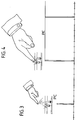
- . la figure 1 : une vue schématique en coupe montrant le couple émetteur-récepteur devant la zone sensible du détecteur à touche optique selon l'invention avec représentation du doigt d'activation ;
- . la figure 2 : la représentation schématique du détecteur dans les deux états correspondant aux deux échantillonnages, et le graphique correspondant illustrant la séquence d'acquisition puis de mesure dans le cas d'une ambiance sombre ou de nuit ;
- . les figures 3 et 4 : des représentations schématiques montrant deux valeurs du niveau haut de la valeur PIC pour deux positions du doigt d'activation, respectivement en approche et en contact avec la surface sensible du détecteur en ambiance sombre ou de nuit.
- . Figure 1: a schematic sectional view showing the transmitter-receiver pair in front of the sensitive area of the optical button detector according to the invention with representation of the activation finger;
- . FIG. 2: the schematic representation of the detector in the two states corresponding to the two samplings, and the corresponding graph illustrating the sequence of acquisition then of measurement in the case of a dark or night atmosphere;
- . FIGS. 3 and 4: schematic representations showing two values of the high level of the PIC value for two positions of the activation finger, respectively in approach and in contact with the sensitive surface of the detector in a dark environment or at night.
Le détecteur optique selon l'invention est formé d'un émetteur 1 d'un rayonnement lumineux visible ou invisible, par exemple infrarouge, et d'un récepteur 2 sensible à ce rayonnement lumineux formant un couple 3 émetteur-récepteur, disposés à proximité l'un de l'autre sous une étendue 4 d'une plaque 5 d'un matériau tel que verre, vitrocéramique ou autre, transparent au rayonnement lumineux visible ou invisible utilisé.The optical detector according to the invention is formed of an emitter 1 of visible or invisible light radiation, for example infrared, and of a
L'étendue 4 située au droit du couple émetteur-récepteur 3 est une zone sensible d'activation ou fenêtre de détection 6 d'une touche optique désignée généralement par 7.The
L'émetteur 1 et le récepteur 2 sont placés l'un à côté de l'autre en face de la zone sensible ou fenêtre de détection 6 de la touche optique, dans une position et à une distance adaptées pour présenter le meilleur rendement de détection possible en fonction de leur angle d'ouverture d'émission ou de réception.Transmitter 1 and
Le récepteur 2 reçoit le faisceau lumineux réfléchi par les deux surfaces inférieure 8 et supérieure 9 de verre ou de vitrocéramique de la plaque 5, mais surtout par la surface supérieure la plus éloignée de la plaque 5, c'est-à-dire celle dont le dos constitue la zone sensible de détection. La réflexion augmente lors de la commande en raison de la présence d'une forme quelconque en contact avec ou à proximité de la zone sensible du détecteur.The
Cette forme, dans le cadre de l'utilisation, est constituée normalement par la sous-face 10 de l'extrémité d'un doigt 11 arrivant à faible distance de ou en contact avec la zone sensible 6.This form, in the context of use, normally consists of the
Elle représente une perturbation optique extérieure de réflexion augmentant suffisamment la réflexion, c'est-à-dire le nombre de rayons réfléchis, pour engendrer une détection systématique après les phases d'acquisition puis de traitement du signal de détection correspondant au mode d'exploitation décrit ci-après.It represents an external optical disturbance of reflection sufficiently increasing the reflection, that is to say the number of rays reflected, to generate a systematic detection after the phases of acquisition then of processing of the detection signal corresponding to the operating mode. described below.
Le mode d'exploitation utilisé dans cette invention est basé sur le procédé suivant, permettant de s'affranchir totalement des perturbations extérieures habituelles.The operating mode used in this invention is based on the following method, making it possible to completely overcome the usual external disturbances.
Il est basé sur la création d'un seuil variable de détection auto-ajustable qui tient compte à tout moment des valeurs des états extrêmes ou antérieurs : dans le cas d'une touche non activée, valeur dite de "REPOS" (état inférieur) et dans le cas d'une touche activée, valeur dite de "PIC" (état supérieur).It is based on the creation of a self-adjusting variable detection threshold which takes into account at any time the values of extreme or previous states: in the case of a key not activated, so-called "REST" value (lower state) and in the case of an activated key, so-called "PIC" value (upper state).
Ces valeurs extrêmes ou antérieures prises en compte pour la détermination du seuil de détection sont d'une part celles de référence stockées dans une première mémoire dite mémoire de référence mais aussi des données obtenues à partir des valeurs antérieures de fonctionnement et stockées dans une mémoire d'ajustement.These extreme or previous values taken into account for the determination of the detection threshold are on the one hand, those of reference stored in a first memory called reference memory but also data obtained from previous operating values and stored in an adjustment memory.
La détermination du seuil s'effectue à partir des valeurs mesurées stockées dans une mémoire de travail et en fonction des données existant dans les mémoires de référence et d'ajustement.The threshold is determined from the measured values stored in a working memory and according to the data existing in the reference and adjustment memories.
Une détection élémentaire s'effectue périodiquement par cycles élémentaires de détection CED répétés. Chaque cycle comprend une séquence d'acquisition SA décomposée en deux phases d'acquisition PA1 et PA2 puis une phase de traitement PT sur une période d'une durée élémentaire faible, durée de l'ordre du temps d'actionnement répété d'une touche mécanique.Elementary detection is carried out periodically by repeated elementary CED detection cycles. Each cycle includes an acquisition sequence SA broken down into two acquisition phases PA1 and PA2 then a processing phase PT over a period of a short elementary duration, duration of the order of the repeated actuation time of a key mechanical.
La prise en compte s'effectue après un nombre prédéterminé de cycles élémentaires de détection CED, par exemple égal à quatre.It is taken into account after a predetermined number of elementary CED detection cycles, for example equal to four.
Un cycle élémentaire de détection se décompose en deux phases d'acquisition et en une phase de traitement.An elementary detection cycle is broken down into two acquisition phases and a processing phase.
-
1. L'émetteur est activé : PA1
En raison de la disposition et des caractéristiques du couple émetteur-récepteur 3, les rayonnements incidents reçus par le récepteur 2 proviennent aussi bien des rayonnements de l'émetteur 1 réfléchis sur la vitre que du rayonnement provenant de sources extérieures arrivant au récepteur 2.
Un premier échantillon PE1 de la valeur du signal est prélevé aux bornes du montage électronique d'acquisition et mis en mémoire pour traitement ultérieur.
Encore inexploitable, cette valeur peut tout aussi bien être le résultat d'une réflexion de l'émetteur à laquelle s'ajoute le rayonnement direct en provenance d'une source extérieure parasite incontrôlable (par exemple le soleil, une lampe d'éclairage domestique.)
On appelle cette première valeur "REFLET". 1. The transmitter is activated: PA1
Due to the arrangement and characteristics of the transmitter-receiver couple 3, the incident radiation received by thereceiver 2 comes from both the radiation from the transmitter 1 reflected on the glass and from radiation from external sources arriving at thereceiver 2.
A first sample PE1 of the signal value is taken at the terminals of the electronic acquisition circuit and stored in memory for further processing.
Still unusable, this value can as well as being the result of a reflection from the transmitter to which is added direct radiation from an uncontrollable parasitic external source (for example the sun, a domestic lighting lamp.)
This first value is called "REFLET". -
2. L'émetteur est désactivé : PA2
Un second échantillon PE2 de la valeur du signal de détection est prélevé aux bornes du montage électronique d'acquisition. Il constitue une bonne image instantanée de l'environnement lumineux dans lequel le couple émetteur-récepteur est plongé.
On appelle cette seconde valeur "AMBIANCE".
Elle est caractérisée par son niveau, à savoir :- faible ou nul = "AMBIANCE" dite "de nuit" ;
- moyen ou saturé = "AMBIANCE" dite "de jour".
A second sample PE2 of the value of the detection signal is taken at the terminals of the electronic acquisition assembly. It provides a good snapshot of the light environment in which the transmitter-receiver pair is immersed.
This second value is called "ATMOSPHERE".
It is characterized by its level, namely:- weak or zero = "ATMOSPHERE" called "at night";
- medium or saturated = "ATMOSPHERE" called "daytime".
En vue de l'assimilation d'une touche à la détection, et ceci quelles que soient les conditions d'ambiances lumineuses dans lesquelles le système est plongé, la première partie de la phase de traitement consistera à effectuer la différence :
D = "REFLET" - "AMBIANCE"
entre les deux valeurs des échantillons PE1 et PE2 pour isoler la partie utile du signal, qui caractérisé la pure réflexion du rayonnement en provenance de l'émetteur.
Deux états distincts du système peuvent alors caractériser cette partie utile du signal correspondant à :
- . un état inférieur caractérisé par une valeur appelée "REPOS" donnée par une touche non activée ;
- . un état supérieur caractérisé par une valeur appelée "PIC" donnée par une touche activée.
Il existe de multiples valeurs "REPOS" et "PIC".
Diverses valeurs importantes ou remarquables sont mémorisées.
Il s'agit des valeurs initiales extrêmes traduisant les caractéristiques mécaniques et physiques du système. Ces valeurs ou les données correspondant à ces valeurs sont stockées lors de la première mise en fonction dans la mémoire de référence et consultées lors de la phase de traitement.
Il s'agit aussi des valeurs antérieures ou des données évolutives correspondant à ces valeurs agissant en tant que valeurs dites d'apprentissage qui sont stockées en permanence dans une mémoire d'ajustement consultée lors de la phase de traitement.
Après pondération et filtrage au cours de la deuxième partie de la phase de traitement, on validera une touche activée si l'augmentation de la différence D est supérieure à un seuil adapté de détection calculé à partir des valeurs de "REPOS" et de "PIC" relevées selon un algorithme particulier en tenant compte des valeurs antérieures et des valeurs de référence.
L'environnement dans lequel le système est placé peut évoluer et se modifier : chauffage des récepteurs, salissures sur la plaque modifiant les caractéristiques de réfraction et suite à des modifications liées à l'opérateur, doigts mouillés ou sales. Ces modifications entraînent des variations non négligeables des valeurs de "REPOS" et de "PIC".
Pour se placer toujours dans les meilleurs conditions de détection, deux séries d'adaptations sont prévues :
- adaptation rapide qui mémorise dans une mémoire de travail les variations des valeurs de "REPOS" et de "PIC", par exemple une valeur toutes les secondes ;
- adaptation lente qui, à partir des valeurs résultant de la première adaptation, les fait évoluer quotidiennement dans une mémoire d'ajustement.
D = "REFLECTION" - "ATMOSPHERE"
between the two values of the samples PE1 and PE2 to isolate the useful part of the signal, which characterizes the pure reflection of the radiation coming from the transmitter.
Two distinct states of the system can then characterize this useful part of the signal corresponding to:
- . a lower state characterized by a value called "REST" given by an inactive key;
- . a higher state characterized by a value called "PIC" given by an activated key.
There are multiple "REPOS" and "PIC" values.
Various important or remarkable values are memorized.
These are the extreme initial values reflecting the mechanical and physical characteristics of the system. These values or the data corresponding to these values are stored during the first start-up in the reference memory and consulted during the processing phase.
These are also previous values or evolutionary data corresponding to these values acting as so-called learning values which are permanently stored in an adjustment memory consulted during the processing phase.
After weighting and filtering during the second part of the treatment phase, an activated key will be validated if the increase in the difference D is greater than a suitable detection threshold calculated from the values of "REST" and "PIC "read according to a particular algorithm taking into account previous values and reference values.
The environment in which the system is placed can evolve and modify: heating of the receivers, soiling on the plate modifying the refraction characteristics and following modifications linked to the operator, wet or dirty fingers. These modifications lead to significant variations in the values of "REST" and "PIC".
To always be in the best detection conditions, two series of adaptations are planned:
- rapid adaptation which memorizes in a working memory the variations of the values of "REST" and "PIC", for example a value every second;
- slow adaptation which, from the values resulting from the first adaptation, makes them evolve daily in an adjustment memory.
Les données correspondant aux valeurs résultant de ces deux adaptations ainsi que celles mémorisées lors de l'initialisation entrent dans le calcul des valeurs limites de dérive du système.The data corresponding to the values resulting from these two adaptations as well as those memorized during initialization enter into the calculation of the limit values of drift of the system.
Ainsi, pendant plusieurs cycles élémentaires de détection CED, on caractérisé la valeur de "PIC" assimilable à une touche activée et indépendante de l'ambiance lumineuse dans laquelle elle est plongée.Thus, during several elementary CED detection cycles, the value of "PIC" can be characterized, which can be assimilated to an activated key independent of the light environment in which it is immersed.
Plus précisément, selon le procédé utilisé, on met en mémoire, après un nombre prédéterminé de cycles élémentaires de détection CED, une variable rendant compte de la valeur de la différence D existant entre les séries de deux échantillons prélevés PE1 et PE2 en vue de la détermination d'un nouveau seuil de détection correspondant aux conditions optiques et d'éclairage du moment.More precisely, according to the method used, a variable is stored in memory, after a predetermined number of elementary cycles of detection CED, accounting for the value of the difference D existing between the series of two samples taken PE1 and PE2 for the purpose of determination of a new detection threshold corresponding to the optical and lighting conditions of the moment.
Selon l'exemple choisi, le nombre de cycles élémentaires avant chaque détection élémentaire correspondant à une séquence d'acquisition est égal à quatre.According to the example chosen, the number of elementary cycles before each elementary detection corresponding to an acquisition sequence is equal to four.
On décrira maintenant le principe général de la prise en compte d'une touche dans les cas extrêmes d'une ambiance de nuit et d'une ambiance de jour.We will now describe the general principle of taking a touch into account in the extreme cases of a night and day atmosphere.
La valeur initiale de la différence mesurée n'est constituée pratiquement que de la réflexion de l'émetteur sur la vitre. L'ambiance parasite est nulle ou faible (figure 2).
" REPOS " = " REFLET " - "AMBIANCE de nuit ".
Un doigt se présente, la réflexion augmente jusqu'à venir se stabiliser à la valeur dite "PIC" lorsque celui-ci se pose sur la surface extérieure de la vitre ou de la plaque de vitrocéramique.
La prise en compte s'effectue après un nombre prédéterminé de cycles pour éviter l'incidence d'un événement furtif.
La valeur "PIC" constitue la donnée utilisée pour la détermination du seuil de détection pour chaque cas.
Celle-ci étant variable selon les conditions de réflexion et les particularités de forme (doigt) activant la touche, on réalise ainsi un véritable auto-ajustement du seuil de détection.The initial value of the measured difference consists practically only of the reflection of the transmitter on the glass. The parasitic atmosphere is zero or weak (Figure 2).
"REPOS" = "REFLET" - "ATMOSPHERE by night".
A finger appears, the reflection increases until it comes to stabilize at the so-called "PIC" value when it is posed on the external surface of the glass or of the glass-ceramic plate.
It is taken into account after a predetermined number of cycles to avoid the impact of a stealth event.
The value "PIC" constitutes the data used for determining the detection threshold for each case.
As this varies according to the reflection conditions and the specific features of the shape (finger) activating the key, a real self-adjustment of the detection threshold is thus achieved.
Elle est caractérisée par un éclairage d'intensité notable extérieur au détecteur, par exemple une lampe à filament alimentée sous la tension du secteur à 50 Hz.
Dans cette ambiance lumineuse perturbée de façon non négligeable, la valeur de la différence donnée par : "REPOS" = "REFLET" - "AMBIANCE de jour" reste semblable à celle initialement connue en ambiance de nuit.
Une tentative d'activation de la touche donne lieu au même état final de prise en compte du rayonnement réfléchi en provenance de l'émetteur.
En effet, le doigt qui se présente au-dessus de la zone sensible forme une ombre qui atténue la puissance lumineuse directe de la source lumineuse parasite extérieure.It is characterized by lighting of notable intensity external to the detector, for example a filament lamp supplied with mains voltage at 50 Hz.
In this light environment disturbed in a non negligible way, the value of the difference given by: "REPOS" = "REFLET" - "ATMOSPHERE by day" remains similar to that initially known in atmosphere by night.
An attempt to activate the key gives rise to the same final state of taking into account the radiation reflected from the transmitter.
Indeed, the finger which is presented above the sensitive zone forms a shadow which attenuates the direct light power of the external parasitic light source.
La figure 2 a pour but d'illustrer le procédé d'établissement du seuil de détection.The purpose of FIG. 2 is to illustrate the method for establishing the detection threshold.
Les figures 3 et 4 montrent deux valeurs "PIC", respectivement pour une position d'approche et de contact du doigt d'activation.Figures 3 and 4 show two "PIC" values, respectively for an approach and contact position of the activation finger.
On expliquera ci-après le fonctionnement général permanent.The permanent general operation will be explained below.
Dès que le montage électronique d'exploitation est alimenté, les phases d'acquisition et de traitement se déroulent automatiquement en vue de déterminer un seuil de détection adapté à l'ambiance.As soon as the electronic operating circuit is supplied, the acquisition and processing phases take place automatically in order to determine a detection threshold adapted to the atmosphere.
En l'absence de commande, ce seuil est celui dit de "REPOS" correspondant à l'état inférieur de la différence :
D = "REFLET" - "AMBIANCE"In the absence of an order, this threshold is that called "REST" corresponding to the lower state of the difference:
D = "REFLECTION" - "ATMOSPHERE"
Lors d'une variation lumineuse extérieure, ce seuil se modifiera automatiquement lors de la séquence d'acquisition et de traitement suivant immédiatement le début de cette variation.During an external light variation, this threshold will automatically change during the acquisition and processing sequence immediately following the start of this variation.
Il s'auto-ajustera à chaque modification des conditions optiques et d'éclairage du milieu environnant.It will self-adjust with each modification of the optical and lighting conditions of the surrounding environment.
Ceci s'applique également à la modification engendrée par l'activation d'une touche par un doigt.This also applies to the modification caused by the activation of a key by a finger.
L'approche du doigt modifiera le degré de luminosité extérieure et introduira, dans le champ de détection, une surface de réflexion.The approach of the finger will modify the degree of external luminosity and will introduce a reflection surface into the detection field.
La vitesse d'approche du doigt n'étant normalement pas élevée par rapport à la périodicité du cycle de détection, il se déroulera plusieurs cycles élémentaires de détection pendant son approche.The finger approach speed is not normally high compared to the periodicity of the detection cycle, there will be several elementary detection cycles during its approach.
Une détection pourra, dans certains cas, avoir déjà eu lieu pour une position rapprochée, mais non de contact, du doigt d'activation de la touche.A detection may, in certain cases, have already taken place for a close position, but not of contact, of the finger for activating the key.
Les figures 3 et 4 ont pour but de montrer la hauteur du niveau "PIC" respectivement pour une position rapprochée et une position de contact du doigt d'activation de la touche.Figures 3 and 4 are intended to show the height of the level "PIC" respectively for a close position and a contact position of the key activation finger.
Il peut donc se produire une détection avant la position de contact si le niveau "PIC" dépasse déjà le seuil de détection correspondant aux conditions lumineuses du moment.It can therefore occur detection before the contact position if the "PIC" level already exceeds the detection threshold corresponding to the light conditions of the moment.
On a ainsi créé, pour une table de cuisson à plaque vitrocéramique, un détecteur à commande par touche optique présentant un seuil auto-ajustable à chaque modification du degré de luminosité environnante ou des conditions optiques du milieu environnant.We have thus created, for a cooktop with a ceramic hob, an optical button control detector having a self-adjusting threshold at each modification of the degree of surrounding brightness or of the optical conditions of the surrounding medium.
Claims (6)
Applications Claiming Priority (2)
| Application Number | Priority Date | Filing Date | Title |
|---|---|---|---|
| FR9200273 | 1992-01-09 | ||
| FR9200273A FR2686147A1 (en) | 1992-01-09 | 1992-01-09 | OPTICAL TOUCH DETECTOR FOR CONTROLLING ONE OF THE FIRES OF A VITRO-CERAMIC COOKTOP. |
Publications (1)
| Publication Number | Publication Date |
|---|---|
| EP0551240A1 true EP0551240A1 (en) | 1993-07-14 |
Family
ID=9425575
Family Applications (1)
| Application Number | Title | Priority Date | Filing Date |
|---|---|---|---|
| EP93440002A Ceased EP0551240A1 (en) | 1992-01-09 | 1993-01-11 | Procedure for the control with the help of an optical sensor on a glass ceramics cooking-plate of a kitchen table. |
Country Status (2)
| Country | Link |
|---|---|
| EP (1) | EP0551240A1 (en) |
| FR (1) | FR2686147A1 (en) |
Cited By (10)
| Publication number | Priority date | Publication date | Assignee | Title |
|---|---|---|---|---|
| EP0780980A3 (en) * | 1995-12-18 | 1998-03-11 | Siemens Aktiengesellschaft | Actuator comprising at least one optoelectronic key |
| EP0772300A3 (en) * | 1995-10-30 | 1998-03-25 | Siemens Aktiengesellschaft | Method for converting IN/OUT analog signals, in particular having different relative amplitudes to corresponding IN/OUT digital signals |
| WO2001054276A1 (en) * | 2000-01-18 | 2001-07-26 | Gerd Reime | Opto-electronic switch which evaluates changes in motion |
| WO2003009476A1 (en) * | 2001-07-16 | 2003-01-30 | Gerd Reime | Optoelectronic device for detecting position and movement and method associated therewith |
| EP1507132A1 (en) * | 2003-08-13 | 2005-02-16 | E.G.O. ELEKTRO-GERÄTEBAU GmbH | Method and circuit for determination of the activation state of at least one optical element |
| EP1517089A1 (en) * | 2003-09-18 | 2005-03-23 | E.G.O. ELEKTRO-GERÄTEBAU GmbH | Control device and control method for an electric household appliance |
| US6965327B2 (en) | 2000-01-18 | 2005-11-15 | Gerd Reime | Device and method for evaluating a useful signal originating from a proximity sensor |
| EP1349279A3 (en) * | 2002-03-29 | 2005-11-23 | Münchner Hybrid Systemtechnik GmbH | Optoelectronic sensor device and illuminable light sensitive switch |
| US9190999B2 (en) | 2006-02-01 | 2015-11-17 | Diehl Ako Stiftung & Co. Kg | Touch-sensitive pushbutton switch |
| US9553579B2 (en) | 2014-12-10 | 2017-01-24 | Pr Electronics A/S | Optical keypad for explosive locations |
Citations (4)
| Publication number | Priority date | Publication date | Assignee | Title |
|---|---|---|---|---|
| GB2161266A (en) * | 1984-07-02 | 1986-01-08 | Antonis Chris Ioannides | Switch device |
| FR2621192A1 (en) * | 1987-09-25 | 1989-03-31 | Perales Manuel | Method and device for controlling an electrical, electronic or computerised device through a transparent surface |
| EP0446642A1 (en) * | 1990-03-13 | 1991-09-18 | Gaggenau-Werke Haus- und Lufttechnik GmbH | Device for switch electric appliances |
| DE4034828C1 (en) * | 1990-11-02 | 1992-01-02 | Daimler-Benz Aktiengesellschaft, 7000 Stuttgart, De | Eliminating influence of external light on opto-electronic keyboard - determining whether keying surface receives outside light or reflection of emitted light is increased as surface is activated |
-
1992
- 1992-01-09 FR FR9200273A patent/FR2686147A1/en not_active Withdrawn
-
1993
- 1993-01-11 EP EP93440002A patent/EP0551240A1/en not_active Ceased
Patent Citations (4)
| Publication number | Priority date | Publication date | Assignee | Title |
|---|---|---|---|---|
| GB2161266A (en) * | 1984-07-02 | 1986-01-08 | Antonis Chris Ioannides | Switch device |
| FR2621192A1 (en) * | 1987-09-25 | 1989-03-31 | Perales Manuel | Method and device for controlling an electrical, electronic or computerised device through a transparent surface |
| EP0446642A1 (en) * | 1990-03-13 | 1991-09-18 | Gaggenau-Werke Haus- und Lufttechnik GmbH | Device for switch electric appliances |
| DE4034828C1 (en) * | 1990-11-02 | 1992-01-02 | Daimler-Benz Aktiengesellschaft, 7000 Stuttgart, De | Eliminating influence of external light on opto-electronic keyboard - determining whether keying surface receives outside light or reflection of emitted light is increased as surface is activated |
Non-Patent Citations (1)
| Title |
|---|
| ELECTRIE vol. 32, no. 4, 1978, BERLIN, DE pages 216 - 217 HASELHOFF 'Zur schaltungstechnischen Realisierung fotoelektrischer Taster' * |
Cited By (14)
| Publication number | Priority date | Publication date | Assignee | Title |
|---|---|---|---|---|
| EP0772300A3 (en) * | 1995-10-30 | 1998-03-25 | Siemens Aktiengesellschaft | Method for converting IN/OUT analog signals, in particular having different relative amplitudes to corresponding IN/OUT digital signals |
| EP0780980A3 (en) * | 1995-12-18 | 1998-03-11 | Siemens Aktiengesellschaft | Actuator comprising at least one optoelectronic key |
| US6965327B2 (en) | 2000-01-18 | 2005-11-15 | Gerd Reime | Device and method for evaluating a useful signal originating from a proximity sensor |
| WO2001054276A1 (en) * | 2000-01-18 | 2001-07-26 | Gerd Reime | Opto-electronic switch which evaluates changes in motion |
| US6828546B2 (en) | 2000-01-18 | 2004-12-07 | Gerd Reime | Opto-electronic switch which evaluates changes in motion |
| CN1294702C (en) * | 2001-07-16 | 2007-01-10 | 格尔德·赖梅 | Optoelectronic device for detecting position and movement and method associated therewith |
| WO2003009476A1 (en) * | 2001-07-16 | 2003-01-30 | Gerd Reime | Optoelectronic device for detecting position and movement and method associated therewith |
| US7456815B2 (en) | 2001-07-16 | 2008-11-25 | Gerd Reime | Optoelectronic device for position and/or movement detection as well as the associated method |
| EP1349279A3 (en) * | 2002-03-29 | 2005-11-23 | Münchner Hybrid Systemtechnik GmbH | Optoelectronic sensor device and illuminable light sensitive switch |
| EP1507132A1 (en) * | 2003-08-13 | 2005-02-16 | E.G.O. ELEKTRO-GERÄTEBAU GmbH | Method and circuit for determination of the activation state of at least one optical element |
| EP1517089A1 (en) * | 2003-09-18 | 2005-03-23 | E.G.O. ELEKTRO-GERÄTEBAU GmbH | Control device and control method for an electric household appliance |
| US7238929B2 (en) | 2003-09-18 | 2007-07-03 | E.G.O Elektro-Geraetebau Gmbh | Operating device and operating method for an electric domestic appliance |
| US9190999B2 (en) | 2006-02-01 | 2015-11-17 | Diehl Ako Stiftung & Co. Kg | Touch-sensitive pushbutton switch |
| US9553579B2 (en) | 2014-12-10 | 2017-01-24 | Pr Electronics A/S | Optical keypad for explosive locations |
Also Published As
| Publication number | Publication date |
|---|---|
| FR2686147A1 (en) | 1993-07-16 |
Similar Documents
| Publication | Publication Date | Title |
|---|---|---|
| EP0551240A1 (en) | Procedure for the control with the help of an optical sensor on a glass ceramics cooking-plate of a kitchen table. | |
| EP0017540B1 (en) | Opto-electric device for localising a luminous point-source | |
| EP0575501B1 (en) | Device for the control of a heating apparatus | |
| FR2583159A1 (en) | OPTICAL POSITION LOCATION DEVICE | |
| WO2014104967A1 (en) | Method and apparatus for detecting visible ambient light | |
| CH643364A5 (en) | APPARATUS FOR LOCATING THE POSITION OF ONE OR MORE OBJECTS. | |
| EP1759333B1 (en) | Optical device for biometric capture by contact and system using said device | |
| EP3482194A1 (en) | Method and device determining soiling of a shield | |
| CH656731A5 (en) | APPARATUS FOR OPTICAL LOCATION OF POSITION. | |
| FR2830622A1 (en) | MONITORING METHOD AND OPTOELECTRONIC SENSOR | |
| FR2522142A1 (en) | ELECTRONIC CLINICAL THERMOMETER | |
| FR2548355A1 (en) | OPTICAL LASER SURVEY SYSTEM | |
| CH634921A5 (en) | APPARATUS FOR LOCATING THE QUANTITY OF SEBUM SECRETED BY A SKIN. | |
| CN104126187B (en) | For the system and method for the noise decrease in bar code signal | |
| EP1221133A1 (en) | Interface unit between a user and an electronic device | |
| EP0203923B1 (en) | Method for scanning a keyboard with capacitive keys and keyboard provided with means for scanning a keyboard according to this method | |
| EP2526621B1 (en) | Control device and electronic device comprising it | |
| FR2767432A1 (en) | Touch-control switch for ceramic cooking hob | |
| WO2006136696A1 (en) | Method and device for rendering interactive a volume or surface | |
| CH379153A (en) | Optical device for measuring a quantity, in particular the temperature of a radiating body | |
| WO2003007266A1 (en) | Remote control device for electrical devices | |
| FR2612647A1 (en) | MODULATION DEVICE FOR A RADIATION DETECTOR DEVICE CAPTURING AN IMAGE FIELD | |
| FR2544109A1 (en) | Interactive electronic practicable device | |
| WO2006084978A1 (en) | Sensor sensitive to the position of a remote moving body | |
| FR2858892A1 (en) | Electrical apparatus e.g. printer, remote control system, has interpretation unit activating control unit depending on characteristics of light signal formed by variations selected by selection unit to effectuate predetermined actions |
Legal Events
| Date | Code | Title | Description |
|---|---|---|---|
| PUAI | Public reference made under article 153(3) epc to a published international application that has entered the european phase |
Free format text: ORIGINAL CODE: 0009012 |
|
| AK | Designated contracting states |
Kind code of ref document: A1 Designated state(s): AT CH DE ES FR GB IT LI |
|
| 17P | Request for examination filed |
Effective date: 19930831 |
|
| RAP1 | Party data changed (applicant data changed or rights of an application transferred) |
Owner name: COMPAGNIE EUROPEENNE POUR L'EQUIPEMENT MENAGER CE |
|
| 17Q | First examination report despatched |
Effective date: 19940504 |
|
| STAA | Information on the status of an ep patent application or granted ep patent |
Free format text: STATUS: THE APPLICATION HAS BEEN REFUSED |
|
| 18R | Application refused |
Effective date: 19951030 |