EP0552397A2 - Thermoelectric therapy device and moisturizing device therefore - Google Patents
Thermoelectric therapy device and moisturizing device therefore Download PDFInfo
- Publication number
- EP0552397A2 EP0552397A2 EP92104941A EP92104941A EP0552397A2 EP 0552397 A2 EP0552397 A2 EP 0552397A2 EP 92104941 A EP92104941 A EP 92104941A EP 92104941 A EP92104941 A EP 92104941A EP 0552397 A2 EP0552397 A2 EP 0552397A2
- Authority
- EP
- European Patent Office
- Prior art keywords
- reservoir
- head
- contact plate
- sleeve
- secured
- Prior art date
- Legal status (The legal status is an assumption and is not a legal conclusion. Google has not performed a legal analysis and makes no representation as to the accuracy of the status listed.)
- Granted
Links
Images


Classifications
-
- A—HUMAN NECESSITIES
- A61—MEDICAL OR VETERINARY SCIENCE; HYGIENE
- A61F—FILTERS IMPLANTABLE INTO BLOOD VESSELS; PROSTHESES; DEVICES PROVIDING PATENCY TO, OR PREVENTING COLLAPSING OF, TUBULAR STRUCTURES OF THE BODY, e.g. STENTS; ORTHOPAEDIC, NURSING OR CONTRACEPTIVE DEVICES; FOMENTATION; TREATMENT OR PROTECTION OF EYES OR EARS; BANDAGES, DRESSINGS OR ABSORBENT PADS; FIRST-AID KITS
- A61F7/00—Heating or cooling appliances for medical or therapeutic treatment of the human body
- A61F7/007—Heating or cooling appliances for medical or therapeutic treatment of the human body characterised by electric heating
-
- A—HUMAN NECESSITIES
- A61—MEDICAL OR VETERINARY SCIENCE; HYGIENE
- A61M—DEVICES FOR INTRODUCING MEDIA INTO, OR ONTO, THE BODY; DEVICES FOR TRANSDUCING BODY MEDIA OR FOR TAKING MEDIA FROM THE BODY; DEVICES FOR PRODUCING OR ENDING SLEEP OR STUPOR
- A61M35/00—Devices for applying media, e.g. remedies, on the human body
- A61M35/003—Portable hand-held applicators having means for dispensing or spreading integral media
-
- F—MECHANICAL ENGINEERING; LIGHTING; HEATING; WEAPONS; BLASTING
- F25—REFRIGERATION OR COOLING; COMBINED HEATING AND REFRIGERATION SYSTEMS; HEAT PUMP SYSTEMS; MANUFACTURE OR STORAGE OF ICE; LIQUEFACTION SOLIDIFICATION OF GASES
- F25B—REFRIGERATION MACHINES, PLANTS OR SYSTEMS; COMBINED HEATING AND REFRIGERATION SYSTEMS; HEAT PUMP SYSTEMS
- F25B21/00—Machines, plants or systems, using electric or magnetic effects
- F25B21/02—Machines, plants or systems, using electric or magnetic effects using Peltier effect; using Nernst-Ettinghausen effect
- F25B21/04—Machines, plants or systems, using electric or magnetic effects using Peltier effect; using Nernst-Ettinghausen effect reversible
-
- A—HUMAN NECESSITIES
- A61—MEDICAL OR VETERINARY SCIENCE; HYGIENE
- A61F—FILTERS IMPLANTABLE INTO BLOOD VESSELS; PROSTHESES; DEVICES PROVIDING PATENCY TO, OR PREVENTING COLLAPSING OF, TUBULAR STRUCTURES OF THE BODY, e.g. STENTS; ORTHOPAEDIC, NURSING OR CONTRACEPTIVE DEVICES; FOMENTATION; TREATMENT OR PROTECTION OF EYES OR EARS; BANDAGES, DRESSINGS OR ABSORBENT PADS; FIRST-AID KITS
- A61F7/00—Heating or cooling appliances for medical or therapeutic treatment of the human body
- A61F7/007—Heating or cooling appliances for medical or therapeutic treatment of the human body characterised by electric heating
- A61F2007/0075—Heating or cooling appliances for medical or therapeutic treatment of the human body characterised by electric heating using a Peltier element, e.g. near the spot to be heated or cooled
-
- A—HUMAN NECESSITIES
- A61—MEDICAL OR VETERINARY SCIENCE; HYGIENE
- A61F—FILTERS IMPLANTABLE INTO BLOOD VESSELS; PROSTHESES; DEVICES PROVIDING PATENCY TO, OR PREVENTING COLLAPSING OF, TUBULAR STRUCTURES OF THE BODY, e.g. STENTS; ORTHOPAEDIC, NURSING OR CONTRACEPTIVE DEVICES; FOMENTATION; TREATMENT OR PROTECTION OF EYES OR EARS; BANDAGES, DRESSINGS OR ABSORBENT PADS; FIRST-AID KITS
- A61F7/00—Heating or cooling appliances for medical or therapeutic treatment of the human body
- A61F7/007—Heating or cooling appliances for medical or therapeutic treatment of the human body characterised by electric heating
- A61F2007/0077—Details of power supply
- A61F2007/0078—Details of power supply with a battery
-
- A—HUMAN NECESSITIES
- A61—MEDICAL OR VETERINARY SCIENCE; HYGIENE
- A61F—FILTERS IMPLANTABLE INTO BLOOD VESSELS; PROSTHESES; DEVICES PROVIDING PATENCY TO, OR PREVENTING COLLAPSING OF, TUBULAR STRUCTURES OF THE BODY, e.g. STENTS; ORTHOPAEDIC, NURSING OR CONTRACEPTIVE DEVICES; FOMENTATION; TREATMENT OR PROTECTION OF EYES OR EARS; BANDAGES, DRESSINGS OR ABSORBENT PADS; FIRST-AID KITS
- A61F7/00—Heating or cooling appliances for medical or therapeutic treatment of the human body
- A61F2007/0087—Hand-held applicators
-
- A—HUMAN NECESSITIES
- A61—MEDICAL OR VETERINARY SCIENCE; HYGIENE
- A61H—PHYSICAL THERAPY APPARATUS, e.g. DEVICES FOR LOCATING OR STIMULATING REFLEX POINTS IN THE BODY; ARTIFICIAL RESPIRATION; MASSAGE; BATHING DEVICES FOR SPECIAL THERAPEUTIC OR HYGIENIC PURPOSES OR SPECIFIC PARTS OF THE BODY
- A61H23/00—Percussion or vibration massage, e.g. using supersonic vibration; Suction-vibration massage; Massage with moving diaphragms
- A61H23/02—Percussion or vibration massage, e.g. using supersonic vibration; Suction-vibration massage; Massage with moving diaphragms with electric or magnetic drive
- A61H23/0254—Percussion or vibration massage, e.g. using supersonic vibration; Suction-vibration massage; Massage with moving diaphragms with electric or magnetic drive with rotary motor
- A61H23/0263—Percussion or vibration massage, e.g. using supersonic vibration; Suction-vibration massage; Massage with moving diaphragms with electric or magnetic drive with rotary motor using rotating unbalanced masses
-
- A—HUMAN NECESSITIES
- A61—MEDICAL OR VETERINARY SCIENCE; HYGIENE
- A61M—DEVICES FOR INTRODUCING MEDIA INTO, OR ONTO, THE BODY; DEVICES FOR TRANSDUCING BODY MEDIA OR FOR TAKING MEDIA FROM THE BODY; DEVICES FOR PRODUCING OR ENDING SLEEP OR STUPOR
- A61M2205/00—General characteristics of the apparatus
- A61M2205/05—General characteristics of the apparatus combined with other kinds of therapy
- A61M2205/054—General characteristics of the apparatus combined with other kinds of therapy with electrotherapy
Definitions
- the field of the invention relates to devices for heating, cooling and moisturizing the surface of the body.
- Hot water bags, ice packs, and the like have commonly been used to alleviate pain, to stimulate the flow of blood, or to restrict the flow of blood beneath the surface of the skin. Vaporizers, steamers and the like have been used to moisturize the skin.
- One of the problems with hot water bags is that the temperature steadily decreases during use, thereby necessitating refilling them with a heated liquid. Ice packs steadily increase in temperature when applied to the skin, and ice must accordingly be added from time to time if a cold temperature is to be maintained. It is also difficult to regulate the temperature of an ice pack or a hot water bottle such that it is neither too cold nor too hot when applied to the skin.
- a number of therapeutic devices have been developed which employ Peltier thermoelectric units for providing heat or cold. Such devices include switches which allow reversing the polarity of the current passing through the thermoelectric units, thereby determining whether a hot or a cold stimulus is to be applied thereby.
- U.S. Patent No. 3,207,159 discloses such a device which includes a probe for heating or cooling selected cutaneous points.
- U.S. Patent Nos. 4,585,002 and 4,860,748 disclose devices which employ microprocessors for controlling the duration and/or intensity of heat and cold generated by Peltier thermoelectric units.
- U.S. Patent Nos. 3,133,539, 3,168,895, 4,640,284 and 4,915,108 disclose various other therapeutic devices for applying heat or cold to the skin.
- a still further object of the invention is to provide a moisturizing device which is easily securable to or removable from a therapeutic heating device.
- a device for moisturizing the skin which includes a housing, the housing including a handle portion to allow the device to be easily held and manipulated using one hand.
- a heat source is mounted to the housing.
- a liquid-filled reservoir is secured to the housing, and preferably removably secured thereto.
- the reservoir includes a wall having a substantially impermeable portion.
- the heat source is positioned in proximity to the reservoir in order to heat the liquid as the flexible, permeable wall of the reservoir is applied to the skin.
- the reservoir is filled prior to mounting it to the housing by a process other than dipping it within a liquid container.
- a cover is preferably provided for protecting against leakage through the permeable wall and evaporation until the device is readied for use.
- a moisturizing device which includes a rigid sleeve, one end of which is adapted to be secured to a heating device, the other end of which has a reservoir mounted thereto.
- the reservoir includes a wall having a substantially impermeable portion and a flexible, permeable portion which is used for engaging the skin. The permeable portion of the wall extends outside the sleeve.
- a therapy device 10 as shown in Fig. 1 is provided.
- the device includes a substantially cylindrical handle 12 and a substantially cylindrical head 14.
- the handle and head are preferably of integral construction, and are made from a thermally conductive material such as aluminum, copper, or an alloy containing both of these metals and silicon.
- the handle includes a cylindrical wall 16 which defines an enclosure 18.
- the enclosure is adapted for receiving at least one battery.
- Two rechargeable, nickel-cadmium batteries 20 are positioned within the enclosure shown in Fig. 1. Other types of batteries may alternatively be employed.
- a tail cap 22 is threadably secured to the end of the handle 12 opposite from the head 14.
- a three-way switch 24 is positioned within the enclosure 18 and adjacent to the tail cap.
- a knob 26 extending outside the tail cap controls the operation of the switch. The opposite end of the switch is connected to a controller board 28.
- the head 14 includes a substantially cylindrical wall 30 having an opening at its front end and an opening at its rear end.
- a face cap 32 is threadably secured to the front end of the head.
- the face cap includes an annular body 34 having a bevelled front wall 36.
- a shoulder 38 is defined by the rear surface of the front wall, as best shown in Fig. 2.
- a vented plate 40 including fins 42 is secured to the rear end of the head.
- a plurality of grooves 44 are defined in the outer surface of the cylindrical wall 30.
- the grooves 44 extend circumferentially about the axis of the head. Alternatively, the grooves may extend axially. Vent openings 46 extend through the cylindrical wall 30 at the grooved portions thereof.
- the cylindrical wall 30 defines a chamber 48.
- the vented plate 40 defines one end of the chamber while a front wall 50 defines the opposite end thereof.
- a thermo module 52 adjoins the front side of the front wall.
- the thermo module includes thermoelectric means including a Peltier effect device.
- a hat-shaped, thermally conductive contact plate 54 adjoins the thermo module.
- a thin, ceramic insulator 55 is positioned between the thermo module 52 and contact plate 54, thereby electrically insulating the latter.
- the contact plate is thermally isolated from the face cap 32, which maintains it in position, by an O-ring 56.
- the face cap may alternatively be made from plastic to provide such thermal insulation.
- An annular space 58 defined between the inner surface of the end cap and the edge of the contact plate also provides thermal isolation.
- the O-ring is slightly compressed between the shoulder 38 of the face cap and a shoulder defined by the hat-shaped contact plate. The contact plate accordingly does not tend to move axially or laterally with respect to the head 14.
- a fan 60 is mounted within the chamber 48, as shown in Fig. 3. Other equivalent means for circulating air could alternatively be employed.
- the fan includes a motor 62 having a blade 64 secured thereto. The blade is positioned adjacent to the vented plate 40.
- a weight 66 may be added to one of the fan blades to cause the head to vibrate slightly when the fan is operated.
- a fluid-filled end piece 68 may be mounted to the front end of the head 14 as shown in dotted lines in Fig. 3.
- the end piece includes a reservoir having a permeable membrane or wall 70 and a rigid, impermeable container 71 which is secured to an elastic sleeve 72.
- the permeable wall 70 conforms to the surface of the skin to which it is applied. It is either heated or cooled depending upon the temperature of the adjoining contact plate.
- the sleeve is preferably substantially non-conductive of heat, while the rigid container portion of the reservoir may be made from a metal which is highly heat-conductive.
- the container may either be slidably positioned within the sleeve so that it moves towards the end of the sleeve when the sleeve is secured to the head, or fixedly secured to one end of the sleeve.
- the reservoir preferably includes no absorbent materials, and is not intended to be filled by dipping it into a container of moisturizing liquid.
- the wall of the reservoir engaging the contact plate should be permeable if the apparatus is to be used for iontophoresis as described below.
- a reservoir in the form of a fluid-filled bag 74 having a flexible porous wall 76 is secured to the front end of the head by a rigid sleeve 78.
- the sleeve 78 is frictionally engageable with the outer surface of the head 14. Moist heat may be accordingly provided by the device 10 when fitted with such a bag as the flexible, impermeable wall portions 77 of the bag readily conduct heat.
- Fig. 4 provides a schematical illustration of one electrical circuit which may be used within the device 10.
- An alternative circuit is shown in Fig. 5.
- This circuit includes the same elements shown in Fig. 4, plus a temperature feedback loop 80, a high voltage source 82, and a voltage regulator 84.
- the temperature feedback loop allows the temperature of the thermo module, and therefore the contact plate, to be maintained within preselected limits.
- the temperature may be varied as a function of time between hot and cold.
- the high voltage source may be a multi- vibratory transformer circuit or the like.
- a polarity switch (not shown) may also be employed in this loop. The switch controls the direction of the current and, therefore, the type of electrical therapy provided (i.e. desensitization (sedation) or stimulation (tetanization)). If employed in conjunction with a reservoir having permeable walls, it may facilitate the absorption of therapeutic liquids via iontophoresis.
- the device In operation, the device is used for applying heat or cold to a relatively large, circular area defined by the outer surface of the contact plate 54.
- the knob 26 is turned to actuate the switch 24. Current flows in a selected direction through the thermo module 52, thereby causing it to heat or cool the contact plate 54.
- the fan is simultaneously actuated, and helps maintain the thermal gradient across the thermo module and the device itself.
- thermo module The relative surface areas and masses of the thermo module, contact plate, head 14 and handle 12 are such that excess heat which may be generated by the thermo module is easily absorbed by the head and handle.
- the head and handle each being thermally conductive and having much larger masses and surface areas than the contact plate, function as a large heat sink which easily dissipates such heat.
- the fan, grooves and vent openings are also strategically positioned to efficiently circulate and exhaust air within the chamber 48. There is accordingly no danger of thermal runaway regardless of how long the device is operated.
- the knob 26 is turned to a different position if one desires to reverse the current flow through the thermo module.
- the fan is actuated regardless of the direction of current flow through the thermo module.
- a pre-filled reservoir may be mounted to the front end of the head as shown in Figs. 3 and 6.
- the size of the pores in the permeable walls is exaggerated in these figures for illustrative purposes. Such pores may simply be pinholes in a material such as latex.
- the walls may simply be membranes which are sufficiently permeable to allow the slow passage of the liquid within the reservoir to pass therethrough. The permeability required will depend upon the particular liquid contained within the reservoir. Liquid within the pouch can slowly escape as the pouch is applied to the skin.
- the knob 26 is turned in the appropriate direction so that heat is applied to the contact plate and, in turn, the impermeable wall of the reservoir and liquid therein.
- liquid as employed herein encompasses liquid materials as well as suspensions, colloids and other such materials which may be used for moisturizing the skin.
- the permeable wall 76 of the fluid-filled bag 74 is preferably protected by a cover 86 when not applied to the skin.
- the cover 86 is removably secured to the sleeve 78 in such a manner that the liquid does not evaporate from or leak out from the permeable wall 76 of the bag 74.
- the front wall 88 of the cover preferably engages the permeable wall 76 when secured to the sleeve.
- the permeable wall 76 extends beyond the end of the sleeve to permit its engagement with the cover 86 or the skin.
- the front wall 88 of the cover may be flexible or semi-rigid.
- a gentle vibratory motion is imparted by the device 10 due to the eccentric weighing of the fan blade 64.
- Such vibration can alternatively be provided by a mechanical vibrator.
- Fig. 8 shows a moisturizing device 90 including a reservoir 92 having a thermally conductive rear wall 94, a porous front wall 96.
- the reservoir is supported by an annular support including a pair of rings 98A, 98B, and is filled with a moisturizing liquid. The edge portions of the reservoir are held between the rings.
- the device 90 is removably securable to an adapter or sleeve 100 made from a semi-rigid material such as plastic.
- the adapter includes a generally frustoconical body 102 having a rim 104 extending inwardly from the relatively large diameter end thereof.
- the rim 104 is positionable within an annular groove 106 in the face cap 32, the groove 106 being shown in Figs. 1 and 11.
- a pair of inwardly extending rims 108, 110 near the relatively small diameter end of the adapter define an annular channel for receiving the annular support 98.
- the smaller end of the adapter include an opening 11
- the heat source may, for example, be a resistive heat source positioned within the reservoir rather than adjacent thereto.
- the reservoir while preferably removable from the heating device, may be integrally formed therewith if an inexpensive heat source is employed. The entire heating and moisturizing assembly would then simply be discarded once all of the moisturizing liquid has been used.
Abstract
Description
- The field of the invention relates to devices for heating, cooling and moisturizing the surface of the body.
- The use of heat, cold and moisture for therapeutic purposes is well known. Hot water bags, ice packs, and the like have commonly been used to alleviate pain, to stimulate the flow of blood, or to restrict the flow of blood beneath the surface of the skin. Vaporizers, steamers and the like have been used to moisturize the skin. One of the problems with hot water bags is that the temperature steadily decreases during use, thereby necessitating refilling them with a heated liquid. Ice packs steadily increase in temperature when applied to the skin, and ice must accordingly be added from time to time if a cold temperature is to be maintained. It is also difficult to regulate the temperature of an ice pack or a hot water bottle such that it is neither too cold nor too hot when applied to the skin.
- A number of therapeutic devices have been developed which employ Peltier thermoelectric units for providing heat or cold. Such devices include switches which allow reversing the polarity of the current passing through the thermoelectric units, thereby determining whether a hot or a cold stimulus is to be applied thereby. U.S. Patent No. 3,207,159 discloses such a device which includes a probe for heating or cooling selected cutaneous points. U.S. Patent Nos. 4,585,002 and 4,860,748 disclose devices which employ microprocessors for controlling the duration and/or intensity of heat and cold generated by Peltier thermoelectric units. U.S. Patent Nos. 3,133,539, 3,168,895, 4,640,284 and 4,915,108 disclose various other therapeutic devices for applying heat or cold to the skin.
- In addition to steamers of the type including an open-ended reservoir, absorbent pads have been secured to electric heating devices in order to allow a person to heat and/or moisturize the skin. U.S. Patent No. 1,653,901 discloses one such device.
- It is an object of the invention to provide a therapeutic device for applying heat, cold or moisture to the skin.
- It is another object of the invention to provide a device which can selectively apply moisture to the skin in a controlled manner.
- A still further object of the invention is to provide a moisturizing device which is easily securable to or removable from a therapeutic heating device.
- In accordance with these and other objects of the invention, a device is provided for moisturizing the skin which includes a housing, the housing including a handle portion to allow the device to be easily held and manipulated using one hand. A heat source is mounted to the housing. A liquid-filled reservoir is secured to the housing, and preferably removably secured thereto. The reservoir includes a wall having a substantially impermeable portion. The heat source is positioned in proximity to the reservoir in order to heat the liquid as the flexible, permeable wall of the reservoir is applied to the skin. The reservoir is filled prior to mounting it to the housing by a process other than dipping it within a liquid container. A cover is preferably provided for protecting against leakage through the permeable wall and evaporation until the device is readied for use.
- In accordance with a further embodiment of the invention, a moisturizing device is provided which includes a rigid sleeve, one end of which is adapted to be secured to a heating device, the other end of which has a reservoir mounted thereto. The reservoir includes a wall having a substantially impermeable portion and a flexible, permeable portion which is used for engaging the skin. The permeable portion of the wall extends outside the sleeve.
-
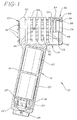
- Fig. 1 is a partially sectional, elevation view of a thermoelectric therapy device in accordance with the invention;
- Fig. 2 is an exploded, side elevation view of a face cap and contact plate used within the device;
- Fig. 3 is a sectional, elevation view of the head of the device having a moisturizing device according to one embodiment of the invention;
- Fig. 4 is a schematical illustration of the electrical circuit employed within the device;
- Fig. 5 is a schematical illustration of an alternative electrical circuit employed within the device;
- Fig. 6 is a sectional view of a porous pouch secured to the front end of the head of the device;
- Fig. 7 is a sectional view showing a moisturizing device and cover secured to the front end of the head of the therapy device;
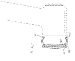
- Fig.8 is a sectional view showing an alternative embodiment of a moisturizing device according to the invention;
- Fig. 9 is a bottom plan showing a holder for a moisturizing device, and
- Fig. 10 is a side elevation view thereof, and
- Fig. 11 is a schematical illustration thereof as secured to a device cooling the skin.
- A
therapy device 10 as shown in Fig. 1 is provided. The device includes a substantiallycylindrical handle 12 and a substantiallycylindrical head 14. The handle and head are preferably of integral construction, and are made from a thermally conductive material such as aluminum, copper, or an alloy containing both of these metals and silicon. - The handle includes a
cylindrical wall 16 which defines anenclosure 18. The enclosure is adapted for receiving at least one battery. Two rechargeable, nickel-cadmium batteries 20 are positioned within the enclosure shown in Fig. 1. Other types of batteries may alternatively be employed. - A
tail cap 22 is threadably secured to the end of thehandle 12 opposite from thehead 14. A three-way switch 24 is positioned within theenclosure 18 and adjacent to the tail cap. Aknob 26 extending outside the tail cap controls the operation of the switch. The opposite end of the switch is connected to acontroller board 28. - Referring now to Figs. 1-3, the
head 14 includes a substantiallycylindrical wall 30 having an opening at its front end and an opening at its rear end. Aface cap 32 is threadably secured to the front end of the head. The face cap includes anannular body 34 having a bevelledfront wall 36. Ashoulder 38 is defined by the rear surface of the front wall, as best shown in Fig. 2. - A vented
plate 40 includingfins 42 is secured to the rear end of the head. A plurality ofgrooves 44 are defined in the outer surface of thecylindrical wall 30. Thegrooves 44 extend circumferentially about the axis of the head. Alternatively, the grooves may extend axially.Vent openings 46 extend through thecylindrical wall 30 at the grooved portions thereof. - The
cylindrical wall 30 defines achamber 48. The ventedplate 40 defines one end of the chamber while afront wall 50 defines the opposite end thereof. Athermo module 52 adjoins the front side of the front wall. The thermo module includes thermoelectric means including a Peltier effect device. A hat-shaped, thermallyconductive contact plate 54 adjoins the thermo module. A thin,ceramic insulator 55 is positioned between thethermo module 52 andcontact plate 54, thereby electrically insulating the latter. The contact plate is thermally isolated from theface cap 32, which maintains it in position, by an O-ring 56. The face cap may alternatively be made from plastic to provide such thermal insulation. Anannular space 58 defined between the inner surface of the end cap and the edge of the contact plate also provides thermal isolation. The O-ring is slightly compressed between theshoulder 38 of the face cap and a shoulder defined by the hat-shaped contact plate. The contact plate accordingly does not tend to move axially or laterally with respect to thehead 14. - A
fan 60 is mounted within thechamber 48, as shown in Fig. 3. Other equivalent means for circulating air could alternatively be employed. The fan includes amotor 62 having ablade 64 secured thereto. The blade is positioned adjacent to the ventedplate 40. Aweight 66 may be added to one of the fan blades to cause the head to vibrate slightly when the fan is operated. - A fluid-filled
end piece 68 may be mounted to the front end of thehead 14 as shown in dotted lines in Fig. 3. The end piece includes a reservoir having a permeable membrane orwall 70 and a rigid,impermeable container 71 which is secured to anelastic sleeve 72. Thepermeable wall 70 conforms to the surface of the skin to which it is applied. It is either heated or cooled depending upon the temperature of the adjoining contact plate. The sleeve is preferably substantially non-conductive of heat, while the rigid container portion of the reservoir may be made from a metal which is highly heat-conductive. The container may either be slidably positioned within the sleeve so that it moves towards the end of the sleeve when the sleeve is secured to the head, or fixedly secured to one end of the sleeve. The reservoir preferably includes no absorbent materials, and is not intended to be filled by dipping it into a container of moisturizing liquid. The wall of the reservoir engaging the contact plate should be permeable if the apparatus is to be used for iontophoresis as described below. - In an alternative embodiment of the invention shown in Fig. 6, a reservoir in the form of a fluid-filled
bag 74 having a flexibleporous wall 76 is secured to the front end of the head by arigid sleeve 78. Thesleeve 78 is frictionally engageable with the outer surface of thehead 14. Moist heat may be accordingly provided by thedevice 10 when fitted with such a bag as the flexible, impermeable wall portions 77 of the bag readily conduct heat. - Fig. 4 provides a schematical illustration of one electrical circuit which may be used within the
device 10. An alternative circuit is shown in Fig. 5. This circuit includes the same elements shown in Fig. 4, plus atemperature feedback loop 80, ahigh voltage source 82, and avoltage regulator 84. The temperature feedback loop allows the temperature of the thermo module, and therefore the contact plate, to be maintained within preselected limits. In addition, the temperature may be varied as a function of time between hot and cold. - Electrical stimulation of the skin and underlying muscles may be provided through the use of the high voltage source and the voltage regulator. The high voltage source may be a multi- vibratory transformer circuit or the like. A polarity switch (not shown) may also be employed in this loop. The switch controls the direction of the current and, therefore, the type of electrical therapy provided (i.e. desensitization (sedation) or stimulation (tetanization)). If employed in conjunction with a reservoir having permeable walls, it may facilitate the absorption of therapeutic liquids via iontophoresis.
- In operation, the device is used for applying heat or cold to a relatively large, circular area defined by the outer surface of the
contact plate 54. Theknob 26 is turned to actuate theswitch 24. Current flows in a selected direction through thethermo module 52, thereby causing it to heat or cool thecontact plate 54. The fan is simultaneously actuated, and helps maintain the thermal gradient across the thermo module and the device itself. - The relative surface areas and masses of the thermo module, contact plate,
head 14 and handle 12 are such that excess heat which may be generated by the thermo module is easily absorbed by the head and handle. The head and handle, each being thermally conductive and having much larger masses and surface areas than the contact plate, function as a large heat sink which easily dissipates such heat. The fan, grooves and vent openings are also strategically positioned to efficiently circulate and exhaust air within thechamber 48. There is accordingly no danger of thermal runaway regardless of how long the device is operated. - The
knob 26 is turned to a different position if one desires to reverse the current flow through the thermo module. The fan is actuated regardless of the direction of current flow through the thermo module. - If one desires to apply moist heat to the skin, a pre-filled reservoir may be mounted to the front end of the head as shown in Figs. 3 and 6. The size of the pores in the permeable walls is exaggerated in these figures for illustrative purposes. Such pores may simply be pinholes in a material such as latex. Alternatively, the walls may simply be membranes which are sufficiently permeable to allow the slow passage of the liquid within the reservoir to pass therethrough. The permeability required will depend upon the particular liquid contained within the reservoir. Liquid within the pouch can slowly escape as the pouch is applied to the skin. The
knob 26 is turned in the appropriate direction so that heat is applied to the contact plate and, in turn, the impermeable wall of the reservoir and liquid therein. The term "liquid" as employed herein encompasses liquid materials as well as suspensions, colloids and other such materials which may be used for moisturizing the skin. - As shown in Fig. 7, the
permeable wall 76 of the fluid-filledbag 74 is preferably protected by acover 86 when not applied to the skin. Thecover 86 is removably secured to thesleeve 78 in such a manner that the liquid does not evaporate from or leak out from thepermeable wall 76 of thebag 74. Thefront wall 88 of the cover preferably engages thepermeable wall 76 when secured to the sleeve. Thepermeable wall 76 extends beyond the end of the sleeve to permit its engagement with thecover 86 or the skin. Thefront wall 88 of the cover may be flexible or semi-rigid. - A gentle vibratory motion is imparted by the
device 10 due to the eccentric weighing of thefan blade 64. Such vibration can alternatively be provided by a mechanical vibrator. - Fig. 8 shows a moisturizing device 90 including a
reservoir 92 having a thermally conductiverear wall 94, a porousfront wall 96. The reservoir is supported by an annular support including a pair ofrings sleeve 100 made from a semi-rigid material such as plastic. The adapter includes a generallyfrustoconical body 102 having arim 104 extending inwardly from the relatively large diameter end thereof. Therim 104 is positionable within anannular groove 106 in theface cap 32, thegroove 106 being shown in Figs. 1 and 11. A pair of inwardly extendingrims annular support 98. The smaller end of the adapter include an opening 112 through which thereservoir 92 protrudes. - Although illustrative embodiments of the present invention have been described herein with reference to the accompanying drawings, it is to be understood that the invention is not limited to those precise embodiments, and that various other changes and modifications may be effected therein by one skilled in the art without departing from the scope or spirit of the invention. The heat source may, for example, be a resistive heat source positioned within the reservoir rather than adjacent thereto. The reservoir, while preferably removable from the heating device, may be integrally formed therewith if an inexpensive heat source is employed. The entire heating and moisturizing assembly would then simply be discarded once all of the moisturizing liquid has been used.
Claims (14)
- A device for moisturizing the skin, comprising:
a housing, said housing including a handle portion;
a heat source mounted to said housing; and
a liquid-filled reservoir containing substantially no absorbent materials and including a wall having a flexible permeable portion which allows the passage of liquid slowly therethrough, said heat source being positioned in proximity to said reservoir and capable of heating the liquid within said reservoir. - A device as described in Claim 1, including a substantially impermeable cover which covers at least said permeable portion of said wall of said reservoir.
- A device as described in Claim 1, wherein said reservoir includes a substantially impermeable portion.
- A device as described any of the preceding claims, wherein said reservoir is secured to a sleeve, said sleeve being coupled to said housing.
- A device as described in Claim 4, wherein said sleeve includes a first end portion and a second end portion, said first end portion including means for removably securing said sleeve to said housing, said second end portion being secured to said wall of said reservoir in such a manner that said permeable portion of said wall of said reservoir extends outside said sleeve.
- A device as described in Claim 5, wherein said reservoir is removably secured to said sleeve.
- A device as described in Claims 1 or 2, wherein said housing includes a contact plate adjacent to said heat source and adjoining said reservoir, and a high voltage source connected to said contact plate.
- A device as described in any of the preceding claims, wherein said housing includes a contact plate adjacent to said reservoir, and means for cooling said contact plate.
- A device described in Claim 6 wherein said housing includes an annular groove, said sleeve including an inwardly extending rim positionable with said groove.
- A moisturizing device for use with a heating device, comprising:
a substantially rigid sleeve including a first end portion and a second end portion, said first end portion being adapted to be secured to a heating device;
a reservoir including a wall having a substantially impermeable portion and a flexible, permeable portion which allows the passage of liquid slowly therethrough, said reservoir being secured to said second end portion of said sleeve such that said permeable portion extends outside said sleeve. - A device as described in Claim 10 wherein said reservoir is removably secured to said sleeve.
- A device as described in Claim 10 wherein said sleeve includes an inwardly extending rim adjacent one end thereof, said reservoir being secured to the opposite end thereof.
- A therapeutic device for heating or cooling the skin and underlying muscles, comprising:
a handle having an exposed outer wall made from a thermally conductive material;
a thermally conductive head secured to said handle such that heat is readily transferable from said head to said handle, said head including a front end and a rear end;
a thermally conductive contact plate secured to said front end of said head;
means for thermally and electrically isolating said contact plate from said head;
thermoelectric means adjoining said contact plate, said thermoelectric means being capable of producing a temperature change in said contact plate in response to an electrical current flowing therethrough;
means for causing current to flow through said thermoelectric means in a first direction, thereby causing said thermoelectric means to heat said contact plate;
means for causing current to flow through said thermoelectric means in a second direction, thereby causing said thermoelectric means to cool said contact plate;
said head including a thermally conductive portion adjoining said thermoelectric means such that said head can function as a heat sink for dissipating heat generated by said thermoelectric means;
a fan positioned within said head; and
a plurality of vent openings extending into said head. - A device as described in Claim 13, including a high voltage source connected to said contact plate.
Applications Claiming Priority (2)
| Application Number | Priority Date | Filing Date | Title |
|---|---|---|---|
| US815958 | 1992-01-02 | ||
| US07/815,958 US5209227A (en) | 1990-09-25 | 1992-01-02 | Thermoelectric therapy device and moisturizing device therefor |
Publications (3)
| Publication Number | Publication Date |
|---|---|
| EP0552397A2 true EP0552397A2 (en) | 1993-07-28 |
| EP0552397A3 EP0552397A3 (en) | 1993-10-27 |
| EP0552397B1 EP0552397B1 (en) | 1997-12-17 |
Family
ID=25219286
Family Applications (1)
| Application Number | Title | Priority Date | Filing Date |
|---|---|---|---|
| EP92104941A Expired - Lifetime EP0552397B1 (en) | 1992-01-02 | 1992-03-21 | Device for moisturizing the skin |
Country Status (3)
| Country | Link |
|---|---|
| US (1) | US5209227A (en) |
| EP (1) | EP0552397B1 (en) |
| DE (1) | DE69223600T2 (en) |
Cited By (6)
| Publication number | Priority date | Publication date | Assignee | Title |
|---|---|---|---|---|
| EP1239239A2 (en) * | 1996-11-04 | 2002-09-11 | Luc Pira | Cryoprobe based on a Peltier module |
| WO2006128703A1 (en) * | 2005-06-02 | 2006-12-07 | Paul Haslauer | Device for applying or administering compresses and a compress holder |
| JP2007037969A (en) * | 2005-05-11 | 2007-02-15 | Beauty Clinical:Kk | Cosmetic apparatus |
| EP1800711A1 (en) * | 2004-09-07 | 2007-06-27 | Yugen Kaisha Beauty Clinical | Cosmetic apparatus |
| WO2013005880A1 (en) * | 2011-07-04 | 2013-01-10 | Jeon Seong Hee | Thermotherapy massage device |
| WO2017089547A1 (en) | 2015-11-26 | 2017-06-01 | Ineos Styrolution Group Gmbh | Polycarbonate-asa blends with antistatic properties using sulfonated alkanes |
Families Citing this family (23)
| Publication number | Priority date | Publication date | Assignee | Title |
|---|---|---|---|---|
| US5476492A (en) * | 1994-02-23 | 1995-12-19 | Unrug; Sophia | Body warmer for therapeutic purposes containing whole herb seed |
| US5447530A (en) * | 1994-03-28 | 1995-09-05 | Guibert; Raul | Periodic pulsed heat technique for inducing analgesic effects |
| US5628769A (en) * | 1994-09-30 | 1997-05-13 | Saringer Research, Inc. | Method and devices for producing somatosensory stimulation using temperature |
| JP2001190586A (en) * | 2000-01-11 | 2001-07-17 | Ohiro Seisakusho:Kk | Facial treatment implement |
| US20040034321A1 (en) * | 2000-10-05 | 2004-02-19 | Seacoast Technologies, Inc. | Conformal pad for neurosurgery and method thereof |
| WO2002028331A1 (en) * | 2000-10-05 | 2002-04-11 | Seacoast Technologies, Inc. | Expandable device for thermal therapy including spiral element |
| KR20010016582A (en) * | 2000-12-22 | 2001-03-05 | 김성숙 | A Skin Beauty Apparatus Of The Controlled Cold And Warmth |
| DE10065592A1 (en) * | 2000-12-28 | 2002-07-04 | Werner Sinnig | Method of hot-cold treatment of migraine involves using head band with pads to apply heat or cold to blood vessels in head |
| GB2422109B (en) * | 2005-01-13 | 2007-02-21 | Richard Mills | Apparatus for providing a heating and cooling effect |
| US8192474B2 (en) * | 2006-09-26 | 2012-06-05 | Zeltiq Aesthetics, Inc. | Tissue treatment methods |
| US9610039B2 (en) * | 2008-07-17 | 2017-04-04 | Prosenex, LLC | Hand-held neuroscreening device |
| CN102258421B (en) * | 2010-05-25 | 2015-11-25 | 皇家飞利浦电子股份有限公司 | For transmitting the equipment of mist to face |
| US9849024B2 (en) | 2010-06-11 | 2017-12-26 | Oasis Medical Solutions | Apparatus for therapeutic cooling and warming of a body portion of a human or mammal |
| KR200465291Y1 (en) * | 2012-02-02 | 2013-02-12 | (주)아모레퍼시픽 | Cosmetic container having massage unit with heater |
| JP5992260B2 (en) * | 2012-07-31 | 2016-09-14 | ヤーマン株式会社 | Hot and cold beauty treatment equipment |
| EP3099261A2 (en) | 2014-01-31 | 2016-12-07 | Zeltiq Aesthetics, Inc. | Treating systems for treating cellulite by cooling |
| US10667985B2 (en) * | 2014-06-16 | 2020-06-02 | Id Lab | Applicator and capsule for such applicator |
| US20160030233A1 (en) * | 2014-08-01 | 2016-02-04 | Empire Technology Development Llc | Apparatuses and methods for cooling a surface |
| US20160242956A1 (en) * | 2015-02-25 | 2016-08-25 | Jennifer Marie Pilby Gomez | Pre and post anesthetic cooling device and method |
| DE102015218094A1 (en) * | 2015-09-21 | 2017-03-23 | Atec Innovation Gmbh | Drive unit for a massage system and massage system with such a drive unit |
| ES2940348T3 (en) * | 2016-08-05 | 2023-05-05 | Koninklijke Philips Nv | skin heat treatment device |
| CN110897856A (en) * | 2019-09-28 | 2020-03-24 | 山东卡蕾兰健康科技有限公司 | Can accomodate formula beauty apparatus |
| DE102021122642A1 (en) | 2021-09-01 | 2023-03-02 | Markus Hintennach | cooling device |
Citations (6)
| Publication number | Priority date | Publication date | Assignee | Title |
|---|---|---|---|---|
| WO1981003608A1 (en) * | 1980-06-19 | 1981-12-24 | E Major | Thermoelectric diagnostic instrument |
| EP0125210A1 (en) * | 1983-05-09 | 1984-11-14 | Pierre Fabre S.A. | Apparatus for treating the respiratory passages |
| EP0135245A2 (en) * | 1983-09-17 | 1985-03-27 | Cosmo Kogyo Kabushiki Kaisha | Apparatus for treating the skin |
| FR2627707A1 (en) * | 1987-09-07 | 1989-09-01 | Fisher & Paykel | MICROPOROUS WALL GAS HUMIDIFICATION APPARATUS |
| WO1990004955A1 (en) * | 1988-11-08 | 1990-05-17 | William Patrick Campbell | Method for increasing body heat transfer |
| EP0376584A2 (en) * | 1988-12-27 | 1990-07-04 | Puritan-Bennett Corporation | Humidifier module for use in a gas humidification assembly |
Family Cites Families (9)
| Publication number | Priority date | Publication date | Assignee | Title |
|---|---|---|---|---|
| US1480353A (en) * | 1921-01-19 | 1924-01-08 | Wappler Electric Co Inc | Electrode |
| US1653901A (en) * | 1923-05-14 | 1927-12-27 | Leo J Haessly | Therapeutical heating and steaming instrument |
| NL285407A (en) * | 1962-06-14 | 1900-01-01 | ||
| US3133539A (en) * | 1962-08-06 | 1964-05-19 | Eidus William | Thermoelectric medical instrument |
| US3168895A (en) * | 1962-11-19 | 1965-02-09 | Okuhara Motoharu | Therapeutic instrument for application of heat and cold |
| US4640284A (en) * | 1985-07-22 | 1987-02-03 | Ruderian Max J | Hot and cold direct contact applicator |
| US4585002A (en) * | 1985-04-22 | 1986-04-29 | Igor Kissin | Method and apparatus for treatment of pain by frequently alternating temperature stimulation |
| US4860748A (en) * | 1988-02-23 | 1989-08-29 | Thermapeutics, Inc. | Thermal pattern generator for pain relief |
| US4915108A (en) * | 1988-06-06 | 1990-04-10 | Sun Shin Ching | Hot and cold compress device |
-
1992
- 1992-01-02 US US07/815,958 patent/US5209227A/en not_active Expired - Fee Related
- 1992-03-21 DE DE69223600T patent/DE69223600T2/en not_active Expired - Fee Related
- 1992-03-21 EP EP92104941A patent/EP0552397B1/en not_active Expired - Lifetime
Patent Citations (6)
| Publication number | Priority date | Publication date | Assignee | Title |
|---|---|---|---|---|
| WO1981003608A1 (en) * | 1980-06-19 | 1981-12-24 | E Major | Thermoelectric diagnostic instrument |
| EP0125210A1 (en) * | 1983-05-09 | 1984-11-14 | Pierre Fabre S.A. | Apparatus for treating the respiratory passages |
| EP0135245A2 (en) * | 1983-09-17 | 1985-03-27 | Cosmo Kogyo Kabushiki Kaisha | Apparatus for treating the skin |
| FR2627707A1 (en) * | 1987-09-07 | 1989-09-01 | Fisher & Paykel | MICROPOROUS WALL GAS HUMIDIFICATION APPARATUS |
| WO1990004955A1 (en) * | 1988-11-08 | 1990-05-17 | William Patrick Campbell | Method for increasing body heat transfer |
| EP0376584A2 (en) * | 1988-12-27 | 1990-07-04 | Puritan-Bennett Corporation | Humidifier module for use in a gas humidification assembly |
Cited By (8)
| Publication number | Priority date | Publication date | Assignee | Title |
|---|---|---|---|---|
| EP1239239A2 (en) * | 1996-11-04 | 2002-09-11 | Luc Pira | Cryoprobe based on a Peltier module |
| EP1239239A3 (en) * | 1996-11-04 | 2004-08-11 | Luc Pira | Cryoprobe based on a Peltier module |
| EP1800711A1 (en) * | 2004-09-07 | 2007-06-27 | Yugen Kaisha Beauty Clinical | Cosmetic apparatus |
| EP1800711A4 (en) * | 2004-09-07 | 2008-04-02 | Yugen Kaisha Beauty Clinical | Cosmetic apparatus |
| JP2007037969A (en) * | 2005-05-11 | 2007-02-15 | Beauty Clinical:Kk | Cosmetic apparatus |
| WO2006128703A1 (en) * | 2005-06-02 | 2006-12-07 | Paul Haslauer | Device for applying or administering compresses and a compress holder |
| WO2013005880A1 (en) * | 2011-07-04 | 2013-01-10 | Jeon Seong Hee | Thermotherapy massage device |
| WO2017089547A1 (en) | 2015-11-26 | 2017-06-01 | Ineos Styrolution Group Gmbh | Polycarbonate-asa blends with antistatic properties using sulfonated alkanes |
Also Published As
| Publication number | Publication date |
|---|---|
| US5209227A (en) | 1993-05-11 |
| EP0552397A3 (en) | 1993-10-27 |
| EP0552397B1 (en) | 1997-12-17 |
| DE69223600T2 (en) | 1998-05-28 |
| DE69223600D1 (en) | 1998-01-29 |
Similar Documents
| Publication | Publication Date | Title |
|---|---|---|
| EP0552397B1 (en) | Device for moisturizing the skin | |
| US5097828A (en) | Thermoelectric therapy device | |
| KR101985569B1 (en) | Cosmetic tool | |
| US3133539A (en) | Thermoelectric medical instrument | |
| US20230381013A1 (en) | Rollable device with features aiding soft tissue release and muscle loosening | |
| US5653741A (en) | Heating and cooling pad | |
| US5327886A (en) | Electronic massage device with cold/hot compress function | |
| US3327713A (en) | Portable thermoelectric hypothermia device | |
| US20100274162A1 (en) | Thermal Massager | |
| US5009228A (en) | Device for relieving ear pain | |
| JP6096819B2 (en) | Beauty equipment | |
| KR101578689B1 (en) | Portable beauty device | |
| JP6096570B2 (en) | Beauty equipment | |
| IT8224764A1 (en) | PROCEDURE FOR CHECKING THE TEMPERATURE OF AN EQUIPMENT AND EQUIPMENT FOR THE IMPLEMENTATION OF THIS PROCEDURE | |
| JP6095451B2 (en) | Beauty equipment | |
| JP2014200496A (en) | Cosmetic instrument | |
| GB2565139A (en) | Cryotherapy device | |
| JP2005006837A (en) | Facial equipment | |
| GB2525412A (en) | Therapeutic Appliance | |
| US11684795B2 (en) | Apparatus and cosmetic method for providing cooling to a skin tissue treatment head | |
| JPH05161691A (en) | Hot moxa cauterizing device | |
| US5948302A (en) | Acrylic warmer for manicuring purposes | |
| WO2010112915A1 (en) | Thermal transfer device | |
| CA2851496C (en) | Therapeutic appliance | |
| JP6153369B2 (en) | Beauty equipment |
Legal Events
| Date | Code | Title | Description |
|---|---|---|---|
| PUAI | Public reference made under article 153(3) epc to a published international application that has entered the european phase |
Free format text: ORIGINAL CODE: 0009012 |
|
| AK | Designated contracting states |
Kind code of ref document: A2 Designated state(s): CH DE FR GB IT LI |
|
| PUAL | Search report despatched |
Free format text: ORIGINAL CODE: 0009013 |
|
| AK | Designated contracting states |
Kind code of ref document: A3 Designated state(s): CH DE FR GB IT LI |
|
| 17P | Request for examination filed |
Effective date: 19940408 |
|
| 17Q | First examination report despatched |
Effective date: 19960130 |
|
| GRAG | Despatch of communication of intention to grant |
Free format text: ORIGINAL CODE: EPIDOS AGRA |
|
| GRAH | Despatch of communication of intention to grant a patent |
Free format text: ORIGINAL CODE: EPIDOS IGRA |
|
| GRAH | Despatch of communication of intention to grant a patent |
Free format text: ORIGINAL CODE: EPIDOS IGRA |
|
| GRAA | (expected) grant |
Free format text: ORIGINAL CODE: 0009210 |
|
| AK | Designated contracting states |
Kind code of ref document: B1 Designated state(s): CH DE FR GB IT LI |
|
| REG | Reference to a national code |
Ref country code: CH Ref legal event code: EP |
|
| REF | Corresponds to: |
Ref document number: 69223600 Country of ref document: DE Date of ref document: 19980129 |
|
| ET | Fr: translation filed | ||
| REG | Reference to a national code |
Ref country code: CH Ref legal event code: NV Representative=s name: FIAMMENGHI-FIAMMENGHI |
|
| ITF | It: translation for a ep patent filed |
Owner name: STUDIO TORTA S.R.L. |
|
| PGFP | Annual fee paid to national office [announced via postgrant information from national office to epo] |
Ref country code: CH Payment date: 19980310 Year of fee payment: 7 |
|
| PLBE | No opposition filed within time limit |
Free format text: ORIGINAL CODE: 0009261 |
|
| STAA | Information on the status of an ep patent application or granted ep patent |
Free format text: STATUS: NO OPPOSITION FILED WITHIN TIME LIMIT |
|
| 26N | No opposition filed | ||
| PG25 | Lapsed in a contracting state [announced via postgrant information from national office to epo] |
Ref country code: LI Free format text: LAPSE BECAUSE OF NON-PAYMENT OF DUE FEES Effective date: 19990331 Ref country code: CH Free format text: LAPSE BECAUSE OF NON-PAYMENT OF DUE FEES Effective date: 19990331 |
|
| REG | Reference to a national code |
Ref country code: CH Ref legal event code: PL |
|
| PGFP | Annual fee paid to national office [announced via postgrant information from national office to epo] |
Ref country code: GB Payment date: 20010321 Year of fee payment: 10 |
|
| PGFP | Annual fee paid to national office [announced via postgrant information from national office to epo] |
Ref country code: FR Payment date: 20010330 Year of fee payment: 10 |
|
| PGFP | Annual fee paid to national office [announced via postgrant information from national office to epo] |
Ref country code: DE Payment date: 20010411 Year of fee payment: 10 |
|
| REG | Reference to a national code |
Ref country code: GB Ref legal event code: IF02 |
|
| PG25 | Lapsed in a contracting state [announced via postgrant information from national office to epo] |
Ref country code: GB Free format text: LAPSE BECAUSE OF NON-PAYMENT OF DUE FEES Effective date: 20020321 |
|
| PG25 | Lapsed in a contracting state [announced via postgrant information from national office to epo] |
Ref country code: DE Free format text: LAPSE BECAUSE OF NON-PAYMENT OF DUE FEES Effective date: 20021001 |
|
| GBPC | Gb: european patent ceased through non-payment of renewal fee |
Effective date: 20020321 |
|
| PG25 | Lapsed in a contracting state [announced via postgrant information from national office to epo] |
Ref country code: FR Free format text: LAPSE BECAUSE OF NON-PAYMENT OF DUE FEES Effective date: 20021129 |
|
| REG | Reference to a national code |
Ref country code: FR Ref legal event code: ST |
|
| PG25 | Lapsed in a contracting state [announced via postgrant information from national office to epo] |
Ref country code: IT Free format text: LAPSE BECAUSE OF NON-PAYMENT OF DUE FEES;WARNING: LAPSES OF ITALIAN PATENTS WITH EFFECTIVE DATE BEFORE 2007 MAY HAVE OCCURRED AT ANY TIME BEFORE 2007. THE CORRECT EFFECTIVE DATE MAY BE DIFFERENT FROM THE ONE RECORDED. Effective date: 20050321 |