EP0558090A2 - Electrical dust collector - Google Patents
Electrical dust collector Download PDFInfo
- Publication number
- EP0558090A2 EP0558090A2 EP93103160A EP93103160A EP0558090A2 EP 0558090 A2 EP0558090 A2 EP 0558090A2 EP 93103160 A EP93103160 A EP 93103160A EP 93103160 A EP93103160 A EP 93103160A EP 0558090 A2 EP0558090 A2 EP 0558090A2
- Authority
- EP
- European Patent Office
- Prior art keywords
- dust
- discharge
- electrodes
- plate
- charged
- Prior art date
- Legal status (The legal status is an assumption and is not a legal conclusion. Google has not performed a legal analysis and makes no representation as to the accuracy of the status listed.)
- Withdrawn
Links
Images


Classifications
-
- B—PERFORMING OPERATIONS; TRANSPORTING
- B03—SEPARATION OF SOLID MATERIALS USING LIQUIDS OR USING PNEUMATIC TABLES OR JIGS; MAGNETIC OR ELECTROSTATIC SEPARATION OF SOLID MATERIALS FROM SOLID MATERIALS OR FLUIDS; SEPARATION BY HIGH-VOLTAGE ELECTRIC FIELDS
- B03C—MAGNETIC OR ELECTROSTATIC SEPARATION OF SOLID MATERIALS FROM SOLID MATERIALS OR FLUIDS; SEPARATION BY HIGH-VOLTAGE ELECTRIC FIELDS
- B03C3/00—Separating dispersed particles from gases or vapour, e.g. air, by electrostatic effect
- B03C3/02—Plant or installations having external electricity supply
- B03C3/04—Plant or installations having external electricity supply dry type
- B03C3/08—Plant or installations having external electricity supply dry type characterised by presence of stationary flat electrodes arranged with their flat surfaces parallel to the gas stream
-
- B—PERFORMING OPERATIONS; TRANSPORTING
- B03—SEPARATION OF SOLID MATERIALS USING LIQUIDS OR USING PNEUMATIC TABLES OR JIGS; MAGNETIC OR ELECTROSTATIC SEPARATION OF SOLID MATERIALS FROM SOLID MATERIALS OR FLUIDS; SEPARATION BY HIGH-VOLTAGE ELECTRIC FIELDS
- B03C—MAGNETIC OR ELECTROSTATIC SEPARATION OF SOLID MATERIALS FROM SOLID MATERIALS OR FLUIDS; SEPARATION BY HIGH-VOLTAGE ELECTRIC FIELDS
- B03C3/00—Separating dispersed particles from gases or vapour, e.g. air, by electrostatic effect
- B03C3/02—Plant or installations having external electricity supply
- B03C3/04—Plant or installations having external electricity supply dry type
- B03C3/12—Plant or installations having external electricity supply dry type characterised by separation of ionising and collecting stations
-
- B—PERFORMING OPERATIONS; TRANSPORTING
- B03—SEPARATION OF SOLID MATERIALS USING LIQUIDS OR USING PNEUMATIC TABLES OR JIGS; MAGNETIC OR ELECTROSTATIC SEPARATION OF SOLID MATERIALS FROM SOLID MATERIALS OR FLUIDS; SEPARATION BY HIGH-VOLTAGE ELECTRIC FIELDS
- B03C—MAGNETIC OR ELECTROSTATIC SEPARATION OF SOLID MATERIALS FROM SOLID MATERIALS OR FLUIDS; SEPARATION BY HIGH-VOLTAGE ELECTRIC FIELDS
- B03C3/00—Separating dispersed particles from gases or vapour, e.g. air, by electrostatic effect
- B03C3/34—Constructional details or accessories or operation thereof
- B03C3/38—Particle charging or ionising stations, e.g. using electric discharge, radioactive radiation or flames
-
- B—PERFORMING OPERATIONS; TRANSPORTING
- B03—SEPARATION OF SOLID MATERIALS USING LIQUIDS OR USING PNEUMATIC TABLES OR JIGS; MAGNETIC OR ELECTROSTATIC SEPARATION OF SOLID MATERIALS FROM SOLID MATERIALS OR FLUIDS; SEPARATION BY HIGH-VOLTAGE ELECTRIC FIELDS
- B03C—MAGNETIC OR ELECTROSTATIC SEPARATION OF SOLID MATERIALS FROM SOLID MATERIALS OR FLUIDS; SEPARATION BY HIGH-VOLTAGE ELECTRIC FIELDS
- B03C3/00—Separating dispersed particles from gases or vapour, e.g. air, by electrostatic effect
- B03C3/34—Constructional details or accessories or operation thereof
- B03C3/36—Controlling flow of gases or vapour
- B03C3/361—Controlling flow of gases or vapour by static mechanical means, e.g. deflector
- B03C3/366—Controlling flow of gases or vapour by static mechanical means, e.g. deflector located in the filter, e.g. special shape of the electrodes
-
- B—PERFORMING OPERATIONS; TRANSPORTING
- B03—SEPARATION OF SOLID MATERIALS USING LIQUIDS OR USING PNEUMATIC TABLES OR JIGS; MAGNETIC OR ELECTROSTATIC SEPARATION OF SOLID MATERIALS FROM SOLID MATERIALS OR FLUIDS; SEPARATION BY HIGH-VOLTAGE ELECTRIC FIELDS
- B03C—MAGNETIC OR ELECTROSTATIC SEPARATION OF SOLID MATERIALS FROM SOLID MATERIALS OR FLUIDS; SEPARATION BY HIGH-VOLTAGE ELECTRIC FIELDS
- B03C3/00—Separating dispersed particles from gases or vapour, e.g. air, by electrostatic effect
- B03C3/34—Constructional details or accessories or operation thereof
- B03C3/36—Controlling flow of gases or vapour
- B03C3/368—Controlling flow of gases or vapour by other than static mechanical means, e.g. internal ventilator or recycler
-
- B—PERFORMING OPERATIONS; TRANSPORTING
- B03—SEPARATION OF SOLID MATERIALS USING LIQUIDS OR USING PNEUMATIC TABLES OR JIGS; MAGNETIC OR ELECTROSTATIC SEPARATION OF SOLID MATERIALS FROM SOLID MATERIALS OR FLUIDS; SEPARATION BY HIGH-VOLTAGE ELECTRIC FIELDS
- B03C—MAGNETIC OR ELECTROSTATIC SEPARATION OF SOLID MATERIALS FROM SOLID MATERIALS OR FLUIDS; SEPARATION BY HIGH-VOLTAGE ELECTRIC FIELDS
- B03C3/00—Separating dispersed particles from gases or vapour, e.g. air, by electrostatic effect
- B03C3/34—Constructional details or accessories or operation thereof
- B03C3/40—Electrode constructions
- B03C3/41—Ionising-electrodes
-
- B—PERFORMING OPERATIONS; TRANSPORTING
- B03—SEPARATION OF SOLID MATERIALS USING LIQUIDS OR USING PNEUMATIC TABLES OR JIGS; MAGNETIC OR ELECTROSTATIC SEPARATION OF SOLID MATERIALS FROM SOLID MATERIALS OR FLUIDS; SEPARATION BY HIGH-VOLTAGE ELECTRIC FIELDS
- B03C—MAGNETIC OR ELECTROSTATIC SEPARATION OF SOLID MATERIALS FROM SOLID MATERIALS OR FLUIDS; SEPARATION BY HIGH-VOLTAGE ELECTRIC FIELDS
- B03C3/00—Separating dispersed particles from gases or vapour, e.g. air, by electrostatic effect
- B03C3/34—Constructional details or accessories or operation thereof
- B03C3/40—Electrode constructions
- B03C3/45—Collecting-electrodes
- B03C3/47—Collecting-electrodes flat, e.g. plates, discs, gratings
-
- B—PERFORMING OPERATIONS; TRANSPORTING
- B03—SEPARATION OF SOLID MATERIALS USING LIQUIDS OR USING PNEUMATIC TABLES OR JIGS; MAGNETIC OR ELECTROSTATIC SEPARATION OF SOLID MATERIALS FROM SOLID MATERIALS OR FLUIDS; SEPARATION BY HIGH-VOLTAGE ELECTRIC FIELDS
- B03C—MAGNETIC OR ELECTROSTATIC SEPARATION OF SOLID MATERIALS FROM SOLID MATERIALS OR FLUIDS; SEPARATION BY HIGH-VOLTAGE ELECTRIC FIELDS
- B03C2201/00—Details of magnetic or electrostatic separation
- B03C2201/10—Ionising electrode has multiple serrated ends or parts
-
- B—PERFORMING OPERATIONS; TRANSPORTING
- B03—SEPARATION OF SOLID MATERIALS USING LIQUIDS OR USING PNEUMATIC TABLES OR JIGS; MAGNETIC OR ELECTROSTATIC SEPARATION OF SOLID MATERIALS FROM SOLID MATERIALS OR FLUIDS; SEPARATION BY HIGH-VOLTAGE ELECTRIC FIELDS
- B03C—MAGNETIC OR ELECTROSTATIC SEPARATION OF SOLID MATERIALS FROM SOLID MATERIALS OR FLUIDS; SEPARATION BY HIGH-VOLTAGE ELECTRIC FIELDS
- B03C2201/00—Details of magnetic or electrostatic separation
- B03C2201/14—Details of magnetic or electrostatic separation the gas being moved electro-kinetically
Definitions
- the present invention relates to an electrical dust collector, and more particularly to an electrical dust collector for electrically collecting and removing particle impurities, such as dust particles, in air.
- Known domestic or office air conditioner has been generally used for conditioning room air optimally and provided with an air filter for purifying the room air by filtering off particle impurities, such as dust particles.
- the known air filter has a problem in that it can not filter off micro impurities, such as cigarette smoke.
- Fig. 1 shows a construction of a general type of known electrical dust collector.
- the electrical dust collector generally includes a main body 1 provided with an inlet 1a and an outlet 1b at opposite ends thereof, respectively.
- a plurality of dust collect electrodes 3 and a plurality of discharge electrodes 4 are longitudinally alternately arranged such that they face in parallel to each other. These electrodes 3 and 4 are applied with high voltages of opposite polarities supplied by a high voltage generator 2.
- the known electric dust collector further includes a blower 5 disposed at a position near the outlet 1b for causing the air to be introduced into the body 1 through the inlet 1a and exhausted therefrom through the outlet 1b after purification.
- the electrodes 3 and 4 are applied with negative (-) voltage and positive (+) voltage, both supplied by the high voltage generator 2, respectively. Hence, an ionization field is formed between the electrodes 3 and 4.
- the dust particles in the room air are ionized by the discharge electrodes 4, which are applied with the positive (+) voltage as aforementioned, and positively charged.
- This positively charged dust particles are then collected by the dust collect electrodes 3 which are applied with the negative (-) voltage.
- the dust particles in the room air are, therefore, removed from the room air and the purified air is exhausted from the main body 1 through the outlet 1b.
- this dust collect part includes a charged plate 6 provided with a plurality of openings 6a.
- This dust collect part further includes a plurality of discharge electrode plates 7 each of which is integrally formed with a plurality of wedge-shaped electrodes 7a horizontally extending from a longitudinal side of the plate 7.
- all of the discharge electrode plates 7 are arranged with respect to the charged plate 6 such that their wedge-shaped electrodes 7a face predetermined positions of individual openings 6a of the charged plate 6.
- a plurality of dust collect plates 8 are arranged between the discharge electrode plates 7 such that the plates 7 and 8 are alternately disposed.
- the discharge plates 7 and the dust collect plates 8 are applied with positive (+) voltage and negative (-) voltage from a high voltage generator (not shown), respectively.
- the dust particles in the room air passing through the collector are ionized with cations by the wedge-shaped electrodes 7a of the discharge plates 7 applied with the positive (+) voltage, and positively charged.
- These positively charged dust particles are then collected by the dust collect plates 8 applied with the negative (-) voltage.
- the dust particles are removed from the room air and the purification of the room air is achieved.
- this known electrical dust collector has a problem in that it reduces productivity and increases manufacturing cost. Furthermore, the dust particles are collected by the additionally mounted dust collect plates 8 and this causes another problem of the dust collector to be resided in that the dust collect efficiency is inevitably deteriorated.
- an object of the present invention to provide an electrical dust collector in which the above problems of the prior are can be overcome, and of which a charged plate for collecting ionized dust particles has a plurality of vertically erected dust collect electrodes facing individual erected discharge electrodes of a discharge plate to be spaced apart therefrom, thereby causing the assembling of the charged plate with the discharge plate to be easily achieved.
- an electrical dust collector for collecting and removing dust particles in a room air by ionizing said dust particles comprising a charged plate being adapted for collecting the ionized dust particles and being provided with a plurality of through holes each of which has an erected dust collect electrode provided at a side thereof; and a discharge plate being adapted for ionizing the dust particles and being arranged to face and to be spaced apart from the charged plate with a distance provided between them, and being provided with a plurality of discharge electrodes which are erected in an opposite direction to the dust collect electrodes of the charged plate.
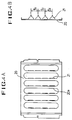
- the electrical dust collector of the present invention includes a charged plate 10 shown in Figs. 3A and 3B.
- the charged plate 10 which is used for collecting ionized and positively charged dust particles when it is applied with negative (-) voltage, is provided with a plurality of generally rectangular through holes 10a.
- the width x1 and length x2 of each hole 10 are determined to be equal to each other.
- this charged plate 10 is integrally provided with a plurality of dust collect electrodes 11 at individual through holes 10a.
- each of the holes 10a is cut at its three sides, and thereafter, the remaining cut part is erected at the other side of the hole 10a such that this remaining cut part is perpendicular to the plane of the charged plate 10. This erected cut part functions as the dust collect electrode 11.
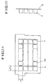
- a discharge plate 20 which is made of a stainless steel and used for ionizing the dust particles when it is applied with positive (+) voltage.
- this discharge plate 20 has a plurality of longitudinal openings 20a each of which is integrally provided with a plurality of wedge-shaped discharge electrodes 21 at a side thereof.
- these wedge-shaped discharge electrodes 21 have individual sharpened tips and are erected such that they are perpendicular to the discharge plate 20.
- the discharge electrodes 21 it is preferred to form the discharge electrodes 21 such that the distances y1, y2 and y3 between them are equal to each other.
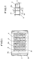
- the charged plate 10 and the discharge plate 20 are assembled into a dust collect part.
- the charged plate 10 is arranged in an insulating main body 30.
- the discharge plate 20 is, thereafter, arranged in the main body 30 such that the discharge plate 20 is parallel to and spaced apart from the charged plate 10 with a predetermined interval therebetween.
- the discharge electrodes 21 of the discharge plate 20 face individual dust collect electrodes 11 of the charged plate 10 in parallel and are spaced apart from the dust collect electrodes 11 by a predetermined distance.
- each of the discharge electrodes 21 is arranged between two dust collect electrodes 11 of the charged plate 10 so as to be parallel to the dust collect electrodes 11.
- the distance between the dust collect electrode 11 and the discharge electrode 21 be x
- the width and the length of the through hole 10a of the charged plate 10 be x1 and x2, respectively
- a thickness of the discharge electrode 21 be t
- the distances between the discharge electrodes 21 of the discharge plate 20 be y1, y2 and y3, respectively, and let a gap between the charged plate 10 and the discharge electrode 21 be t1
- FIGs. 7A and 7B there are shown graphs representing relation of dust collect efficiency of the electrical dust collector of this invention with respect to the distance between the dust collect electrode 11 and the discharge electrode 21.
- the distance x of 6.0 - 6.5 mm causes the optimum dust collect efficiency of the dust collector when the average diameter of the dust particles in the room air is 0.3 ⁇ mm
- the distance x of 6.0 - 6.9 mm causes the optimum dust collect efficiency of the dust collector when the average diameter of the dust particles is 0.5 ⁇ mm.
- uniform electric potential and uniform electric field are provided between the plates 10 and 20.
- Such a uniform electric potential as well as the uniform electric field is provided because the dust collect electrodes 11 of the charged plate 10 and the discharge electrodes 21 of the discharge plate 20 are characteristically arranged, as aforementioned, such that no wedge-shaped electrode is disposed in the through holes 10a of the charged plate 10.
- the uniform electric potential and the uniform electric field prevent generation of corona discharge and this causes uniform discharge between the charged plate 10 and the discharge plate 20.
- the room air containing dust particles passing by the discharge electrodes 21 and passing through the through holes 10a of the charged plate 10 are applied with high frequency of 800 Hz - 1500 KHz. This makes the dust particles be divided into micro particles which are in turn charged with cations. These positively charged micro dust particles are easily collected by the negatively charged plate 10.
- the present invention provides an electrical dust collector which includes a discharge plate provided with a plurality of longitudinal openings, each having a plurality of vertically erected discharge electrodes having individual sharpened tips.
- the present dust collector further includes a charged plate having a plurality of through holes provided with individual dust collect electrodes.
- the discharge plate and the charged plate are assembled into a dust collect part such that the discharge electrodes of the discharge plate face individual dust collect electrodes of the charged plate in parallel and are spaced apart therefrom by a predetermined distance.
- the present invention causes a uniform discharge between the dust collect electrodes and the discharge electrodes and, as a result, provides an advantage in that the dust collect efficiency of the dust collector is remarkably improved.
- the charged plate and the discharge plate can be easily assembled.
- another advantage of this invention is resided in that the manufacturing cost of the electrical dust collector is reduced.
Abstract
An electrical dust collector for collecting and removing dust particles in a room air by ionizing the dust particles. The charged plate (10) collects the ionized dust particles and is provided with a plurality of through holes (10a) each of which has an erected dust collect electrode (11) provided at a side thereof. The discharge plate (20) ionizes the dust particles and is arranged with respect to the charged plate (10) such that it faces and is spaced apart from the charged plate (10) with a distance provided between them. The discharge plate (20) is provided with a plurality of discharge electrodes (21) which is erected in an opposite direction to the dust collect electrodes (11) of the charged plate (10). This dust collector causes a uniform electric potential and a uniform electric field to be provided between the charged plate (10) and the discharge plate (20) and, as a result, provides a uniform charge between the plates, thereby improving the dust collect efficiency.
Description
- The present invention relates to an electrical dust collector, and more particularly to an electrical dust collector for electrically collecting and removing particle impurities, such as dust particles, in air.
- Known domestic or office air conditioner has been generally used for conditioning room air optimally and provided with an air filter for purifying the room air by filtering off particle impurities, such as dust particles. However, the known air filter has a problem in that it can not filter off micro impurities, such as cigarette smoke.
- In order to overcome such a problem of the known air filter, there has been proposed several types of electrical dust collectors. Fig. 1 shows a construction of a general type of known electrical dust collector. As shown in this drawing, the electrical dust collector generally includes a main body 1 provided with an
inlet 1a and an outlet 1b at opposite ends thereof, respectively. In the main body 1 between theinlet 1a and the outlet 1b, a plurality of dust collectelectrodes 3 and a plurality ofdischarge electrodes 4 are longitudinally alternately arranged such that they face in parallel to each other. Theseelectrodes high voltage generator 2. The known electric dust collector further includes ablower 5 disposed at a position near the outlet 1b for causing the air to be introduced into the body 1 through theinlet 1a and exhausted therefrom through the outlet 1b after purification. - In operation of this type of known electric dust collector, the
electrodes high voltage generator 2, respectively. Hence, an ionization field is formed between theelectrodes discharge electrodes 4, which are applied with the positive (+) voltage as aforementioned, and positively charged. This positively charged dust particles are then collected by the dust collectelectrodes 3 which are applied with the negative (-) voltage. The dust particles in the room air are, therefore, removed from the room air and the purified air is exhausted from the main body 1 through the outlet 1b. - However, it has been noted that the dust collect efficiency of the known electric dust collector are remarkably affected by construction and arrangement of the dust collect
electrodes 3 and thedischarge electrodes 4. - With reference to Fig. 2, which is a perspective view of an embodiment of a dust collect part of the known electric dust collector, this dust collect part includes a charged plate 6 provided with a plurality of
openings 6a. This dust collect part further includes a plurality ofdischarge electrode plates 7 each of which is integrally formed with a plurality of wedge-shaped electrodes 7a horizontally extending from a longitudinal side of theplate 7. Here, all of thedischarge electrode plates 7 are arranged with respect to the charged plate 6 such that their wedge-shaped electrodes 7a face predetermined positions ofindividual openings 6a of the charged plate 6. In addition, a plurality of dust collectplates 8 are arranged between thedischarge electrode plates 7 such that theplates discharge plates 7 and the dust collectplates 8 are applied with positive (+) voltage and negative (-) voltage from a high voltage generator (not shown), respectively. In the same manner as described in the electrical dust collector of Fig. 1, the dust particles in the room air passing through the collector are ionized with cations by the wedge-shaped electrodes 7a of thedischarge plates 7 applied with the positive (+) voltage, and positively charged. These positively charged dust particles are then collected by the dust collectplates 8 applied with the negative (-) voltage. Thus, the dust particles are removed from the room air and the purification of the room air is achieved. - However, it is very difficult to position the
discharge electrode plates 7 with respect to the charged plate 6 such that the wedge-shaped electrodes 7a of theplates 7 accurately face the predetermined positions of theindividual openings 6a of the charged plates 6. In this regard, this known electrical dust collector has a problem in that it reduces productivity and increases manufacturing cost. Furthermore, the dust particles are collected by the additionally mounteddust collect plates 8 and this causes another problem of the dust collector to be resided in that the dust collect efficiency is inevitably deteriorated. - It is, therefore, an object of the present invention to provide an electrical dust collector in which the above problems of the prior are can be overcome, and of which a charged plate for collecting ionized dust particles has a plurality of vertically erected dust collect electrodes facing individual erected discharge electrodes of a discharge plate to be spaced apart therefrom, thereby causing the assembling of the charged plate with the discharge plate to be easily achieved.
- It is another object of the present invention to provide an electrical dust collector which reduces manufacturing cost.
- It is still another object of the present invention to provide an electrical dust collector which improves dust collect efficiency by introducing uniform discharge between dust collect electrodes and discharge electrodes.
- In accordance with a preferred embodiment of the present invention, the above objects can be accomplished by providing an electrical dust collector for collecting and removing dust particles in a room air by ionizing said dust particles comprising a charged plate being adapted for collecting the ionized dust particles and being provided with a plurality of through holes each of which has an erected dust collect electrode provided at a side thereof; and a discharge plate being adapted for ionizing the dust particles and being arranged to face and to be spaced apart from the charged plate with a distance provided between them, and being provided with a plurality of discharge electrodes which are erected in an opposite direction to the dust collect electrodes of the charged plate.
- Other objects and aspects of the invention will become apparent from the following description of embodiments with reference to the accompanying drawings in which:
- Fig. 1 is a schematic view showing a construction of a general type of known electric dust collector;
- Fig. 2 is a partially exploded perspective view of an embodiment of a dust collect part of a known electric dust collector;
- Fig. 3A is an elevational view; and
- Fig. 3B is a side view;
- Fig. 4A is an elevational view; and
- Fig. 4B is a side view;
- Fig. 5 is an elevational view of a dust collect part provided by assembling the charged plate with the discharge plate of the present invention;
- Fig. 6 is an enlarged sectional view of the circled section A of Fig. 5; and
- Figs. 7A and 7B are graphs showing relation of dust collect efficiency of the electrical dust collector of the present invention with respect to a distance between a dust collect electrode of the charged plate and a discharge electrode of the discharged plate.
- The electrical dust collector of the present invention includes a
charged plate 10 shown in Figs. 3A and 3B. As depicted in these drawings, thecharged plate 10, which is used for collecting ionized and positively charged dust particles when it is applied with negative (-) voltage, is provided with a plurality of generally rectangular throughholes 10a. The width x₁ and length x₂ of eachhole 10 are determined to be equal to each other. In addition, thischarged plate 10 is integrally provided with a plurality of dust collectelectrodes 11 at individual throughholes 10a. In order to provide the dust collectelectrodes 11 for thecharged plate 10, each of theholes 10a is cut at its three sides, and thereafter, the remaining cut part is erected at the other side of thehole 10a such that this remaining cut part is perpendicular to the plane of thecharged plate 10. This erected cut part functions as the dust collectelectrode 11. - Turning to Figs. 4A and 4B, there is shown a
discharge plate 20 which is made of a stainless steel and used for ionizing the dust particles when it is applied with positive (+) voltage. As depicted in Fig. 4A, thisdischarge plate 20 has a plurality oflongitudinal openings 20a each of which is integrally provided with a plurality of wedge-shaped discharge electrodes 21 at a side thereof. As best seen in Fig. 4B, these wedge-shapeddischarge electrodes 21 have individual sharpened tips and are erected such that they are perpendicular to thedischarge plate 20. - Here, it is preferred to form the
discharge electrodes 21 such that the distances y₁, y₂ and y₃ between them are equal to each other. - Referring next to Fig. 5, the charged
plate 10 and thedischarge plate 20 are assembled into a dust collect part. In assembling theplates plate 10 is arranged in an insulatingmain body 30. Thedischarge plate 20 is, thereafter, arranged in themain body 30 such that thedischarge plate 20 is parallel to and spaced apart from the chargedplate 10 with a predetermined interval therebetween. As a result of such an assembling of theplates discharge electrodes 21 of thedischarge plate 20 face individual dust collectelectrodes 11 of the chargedplate 10 in parallel and are spaced apart from the dust collectelectrodes 11 by a predetermined distance. - Otherwise stated, as best seen in Fig. 6, each of the
discharge electrodes 21 is arranged between two dust collectelectrodes 11 of the chargedplate 10 so as to be parallel to the dust collectelectrodes 11. - Here, when let the distance between the dust collect
electrode 11 and thedischarge electrode 21 be x, let the width and the length of the throughhole 10a of the chargedplate 10 be x₁ and x₂, respectively, let a thickness of thedischarge electrode 21 be t, let the distances between thedischarge electrodes 21 of thedischarge plate 20 be y₁, y₂ and y₃, respectively, and let a gap between the chargedplate 10 and thedischarge electrode 21 be t₁, the distance x between theelectrodes

wherein x₁ = x₂, y₁ = y₂ = y₃ and t = t₁. - Referring to Figs. 7A and 7B, there are shown graphs representing relation of dust collect efficiency of the electrical dust collector of this invention with respect to the distance between the dust collect
electrode 11 and thedischarge electrode 21. As represented in these graphs, the distance x of 6.0 - 6.5 mm causes the optimum dust collect efficiency of the dust collector when the average diameter of the dust particles in the room air is 0.3 µmm, whilst the distance x of 6.0 - 6.9 mm causes the optimum dust collect efficiency of the dust collector when the average diameter of the dust particles is 0.5 µmm. - Hereinafter, the operational effect of the present electrical dust collector will be described.
- Upon applying the positive (+) voltage to the
discharge plate 20 at the same time of applying the negative (-) voltage to the chargedplate 10, uniform electric potential and uniform electric field are provided between theplates electrodes 11 of the chargedplate 10 and thedischarge electrodes 21 of thedischarge plate 20 are characteristically arranged, as aforementioned, such that no wedge-shaped electrode is disposed in the throughholes 10a of the chargedplate 10. - The uniform electric potential and the uniform electric field prevent generation of corona discharge and this causes uniform discharge between the charged
plate 10 and thedischarge plate 20. Hence, the room air containing dust particles passing by thedischarge electrodes 21 and passing through the throughholes 10a of the chargedplate 10 are applied with high frequency of 800 Hz - 1500 KHz. This makes the dust particles be divided into micro particles which are in turn charged with cations. These positively charged micro dust particles are easily collected by the negatively chargedplate 10. - As described above, the present invention provides an electrical dust collector which includes a discharge plate provided with a plurality of longitudinal openings, each having a plurality of vertically erected discharge electrodes having individual sharpened tips. The present dust collector further includes a charged plate having a plurality of through holes provided with individual dust collect electrodes. The discharge plate and the charged plate are assembled into a dust collect part such that the discharge electrodes of the discharge plate face individual dust collect electrodes of the charged plate in parallel and are spaced apart therefrom by a predetermined distance. Hence, the present invention causes a uniform discharge between the dust collect electrodes and the discharge electrodes and, as a result, provides an advantage in that the dust collect efficiency of the dust collector is remarkably improved. Furthermore, the charged plate and the discharge plate can be easily assembled. Thus, another advantage of this invention is resided in that the manufacturing cost of the electrical dust collector is reduced.
- Having described specific preferred embodiments of the invention with reference to the accompanying drawings, it is to be understood that the invention is not limited to those precise embodiments, and that various changes and modifications may be effected therein by one skilled in the art without departing from the scope or spirit of the invention as defined in the appended claims.
Claims (4)
- An electrical dust collector for collecting and removing dust particles by ionizing said dust particles, characterized by
charged means (10) for collecting the ionized dust particles, said charged means (10) being provided with a plurality of through holes (10a), each said through hole (10a) having an erected dust collect electrode (11) provided at a side thereof; and
discharge means (20) for ionizing said dust particles, said discharge means (20) being arranged to face and to be spaced apart from said charged means (10) with a predetermined distance, and being provided with a plurality of discharge electrodes (21), said discharge electrodes (21) being erected in an opposite direction to said dust collect electrodes (11) of the charged means (10). - An electrical dust collector according to claim 1, wherein said discharge electrodes (21) of the discharge means (20) are positioned to be aligned with centers of said through holes (10a) of the charged means (10), respectively.
- An electrical dust collector according to claim 1 or 2,
wherein said discharge electrodes (21) of the discharge means (20) are alternately positioned between said dust collect electrodes (11) of the charged means (10) so as to be parallel to said dust collect electrodes (11). - An electrical dust collector according to any of claims 1 to 3,
wherein each said discharge electrode (21) of the discharge means (20) is a wedge-shaped electrode having a sharpened tip.
Applications Claiming Priority (2)
| Application Number | Priority Date | Filing Date | Title |
|---|---|---|---|
| KR1019920003207A KR930017626A (en) | 1992-02-28 | 1992-02-28 | Electrostatic precipitator |
| KR320792 | 1992-02-28 |
Publications (2)
| Publication Number | Publication Date |
|---|---|
| EP0558090A2 true EP0558090A2 (en) | 1993-09-01 |
| EP0558090A3 EP0558090A3 (en) | 1993-11-03 |
Family
ID=19329669
Family Applications (1)
| Application Number | Title | Priority Date | Filing Date |
|---|---|---|---|
| EP19930103160 Withdrawn EP0558090A3 (en) | 1992-02-28 | 1993-02-27 | Electrical dust collector |
Country Status (8)
| Country | Link |
|---|---|
| US (1) | US5322550A (en) |
| EP (1) | EP0558090A3 (en) |
| JP (1) | JPH0679196A (en) |
| KR (1) | KR930017626A (en) |
| CN (1) | CN1088853A (en) |
| AU (1) | AU664069B2 (en) |
| NZ (1) | NZ247027A (en) |
| TW (1) | TW221382B (en) |
Cited By (5)
| Publication number | Priority date | Publication date | Assignee | Title |
|---|---|---|---|---|
| WO1996011745A1 (en) * | 1994-10-17 | 1996-04-25 | Jing Mei Industrial Holdings, Ltd. | Ionizer |
| US6464754B1 (en) | 1999-10-07 | 2002-10-15 | Kairos, L.L.C. | Self-cleaning air purification system and process |
| WO2004033104A1 (en) * | 2002-09-21 | 2004-04-22 | Forschungszentrum Karlsruhe Gmbh | Ionizer and use thereof in an exhaust gas purifying installation for condensed humid and/or droplet-loaded gases |
| US6810832B2 (en) | 2002-09-18 | 2004-11-02 | Kairos, L.L.C. | Automated animal house |
| CN102218373A (en) * | 2010-01-29 | 2011-10-19 | 三星电子株式会社 | Electric dust removing device and home appliance having the electric dust removing device |
Families Citing this family (29)
| Publication number | Priority date | Publication date | Assignee | Title |
|---|---|---|---|---|
| IT1264222B1 (en) * | 1993-09-22 | 1996-09-23 | Salvatore Vanella | FILTER DEVICE FOR AIR POLLUTION |
| US5484472C1 (en) * | 1995-02-06 | 2001-02-20 | Wein Products Inc | Miniature air purifier |
| US5685838A (en) * | 1995-04-17 | 1997-11-11 | Xomed-Treace, Inc. | Sinus debrider apparatus |
| US5622543A (en) * | 1995-09-20 | 1997-04-22 | Yang; Chen-Ho | Rectilinear turbulent flow type air purifier |
| US5733360A (en) * | 1996-04-05 | 1998-03-31 | Environmental Elements Corp. | Corona discharge reactor and method of chemically activating constituents thereby |
| US5667564A (en) * | 1996-08-14 | 1997-09-16 | Wein Products, Inc. | Portable personal corona discharge device for destruction of airborne microbes and chemical toxins |
| US5702507A (en) * | 1996-09-17 | 1997-12-30 | Yih Change Enterprise Co., Ltd. | Automatic air cleaner |
| KR100234085B1 (en) * | 1997-12-27 | 1999-12-15 | 윤종용 | Electrostatic precipitator |
| US6126722A (en) * | 1998-07-28 | 2000-10-03 | The United States Of America As Represented By The Secretary Of Agriculture | Electrostatic reduction system for reducing airborne dust and microorganisms |
| JP3059438B1 (en) * | 1999-05-31 | 2000-07-04 | 株式会社オーデン | Electric dust collection unit |
| ES2383686T3 (en) * | 2003-06-05 | 2012-06-25 | Daikin Industries, Ltd. | Discharge device and air purifier |
| AU2004302996B2 (en) * | 2003-08-29 | 2008-05-29 | Daikin Industries, Ltd. | Discharge device and air purifying device |
| KR100745952B1 (en) * | 2003-08-29 | 2007-08-02 | 다이킨 고교 가부시키가이샤 | Gas treating apparatus |
| JP2006021077A (en) * | 2004-07-06 | 2006-01-26 | Matsushita Electric Ind Co Ltd | Electrical dust precipitation unit |
| TWI283192B (en) * | 2004-12-21 | 2007-07-01 | Ind Tech Res Inst | A flat-plate type static dust-connecting device |
| AU2007259679B2 (en) * | 2006-06-15 | 2011-02-24 | Daikin Industries, Ltd. | Dust collector |
| EP2039431A4 (en) * | 2006-06-15 | 2013-01-23 | Daikin Ind Ltd | Dust collector |
| US8657937B2 (en) * | 2008-11-14 | 2014-02-25 | Daikin Industries, Ltd. | Dust collector |
| JP5761461B2 (en) * | 2012-07-31 | 2015-08-12 | 富士電機株式会社 | Electric dust collector |
| CN104148184B (en) * | 2014-08-26 | 2017-08-01 | 珠海格力电器股份有限公司 | The charged component of electrostatic precipitator |
| JP6408861B2 (en) * | 2014-10-23 | 2018-10-17 | アマノ株式会社 | Electric dust collector and fryer integrated electrostatic dust collection unit |
| KR102201298B1 (en) * | 2015-02-17 | 2021-01-11 | 한온시스템 주식회사 | Electrification apparatus for electrostatic dust collector |
| CN106269256A (en) * | 2016-08-10 | 2017-01-04 | 福建龙净环保股份有限公司 | A kind of electrostatic precipitator for gas cleaning |
| KR102586516B1 (en) * | 2018-07-20 | 2023-10-06 | 엘지전자 주식회사 | Electrification apparatus for electric dust collector and air conditioner for vehicle comprising the same |
| KR102636066B1 (en) * | 2018-07-20 | 2024-02-08 | 엘지전자 주식회사 | Electrification apparatus for electric dust collector and air conditioner for vehicle comprising the same |
| KR102534790B1 (en) * | 2018-07-23 | 2023-05-19 | 엘지전자 주식회사 | Electrification apparatus for electric dust collector and control method for the same |
| WO2020026370A1 (en) * | 2018-08-01 | 2020-02-06 | 三菱日立パワーシステムズ環境ソリューション株式会社 | Electrostatic precipitator |
| CN114054208B (en) * | 2020-07-30 | 2023-12-05 | Lg电子株式会社 | Charging device for electric dust collection |
| CN114054209B (en) * | 2020-07-30 | 2023-12-05 | Lg电子株式会社 | Charging device for electric dust collection |
Citations (4)
| Publication number | Priority date | Publication date | Assignee | Title |
|---|---|---|---|---|
| FR883953A (en) * | 1941-04-28 | 1943-07-28 | Heinrich Koppers Ges M B H | Gas treatment device by electric discharges |
| DE1901981A1 (en) * | 1969-01-16 | 1970-08-20 | Hesselbrock Dipl Ing Hermann | Precipitation electrode for electric gas - cleaner |
| GB1445753A (en) * | 1973-11-15 | 1976-08-11 | Mead Corp | Apparatus and method for electrical precipitation |
| US4673416A (en) * | 1983-12-05 | 1987-06-16 | Nippondenso Co., Ltd. | Air cleaning apparatus |
Family Cites Families (8)
| Publication number | Priority date | Publication date | Assignee | Title |
|---|---|---|---|---|
| US2195431A (en) * | 1935-10-09 | 1940-04-02 | Koppers Co Inc | Gas treating apparatus |
| US2575181A (en) * | 1948-07-14 | 1951-11-13 | Wheeling Steel Corp | Precipitator collecting electrode |
| US2936851A (en) * | 1957-06-07 | 1960-05-17 | Richard R Cook | Air purifier |
| GB1142527A (en) * | 1966-09-08 | 1969-02-12 | Aerocoat Sa | Improvements in or relating to apparatus for applying powder coatings to articles |
| US3418792A (en) * | 1967-06-26 | 1968-12-31 | Koppers Co Inc | Modular collector electrode for electrostatic precipitators |
| US3820306A (en) * | 1969-02-25 | 1974-06-28 | American Standard Inc | Electrostatic precipitator employing dielectric grids |
| US3668836A (en) * | 1970-01-22 | 1972-06-13 | Chemical Construction Corp | Electrostatic precipitator |
| DE3418577A1 (en) * | 1984-05-18 | 1985-11-21 | Masuda, Senichi, Tokio/Tokyo | FILM SHAPED DUST COLLECTING ELECTRODES AND ELECTRIC DUST COLLECTING DEVICE WITH A STACK OF SUCH DUST COLLECTING ELECTRODES |
-
1992
- 1992-02-28 KR KR1019920003207A patent/KR930017626A/en not_active Application Discontinuation
-
1993
- 1993-02-27 TW TW082101484A patent/TW221382B/zh active
- 1993-02-27 EP EP19930103160 patent/EP0558090A3/en not_active Withdrawn
- 1993-02-27 CN CN93103491A patent/CN1088853A/en active Pending
- 1993-03-01 AU AU33887/93A patent/AU664069B2/en not_active Ceased
- 1993-03-01 NZ NZ247027A patent/NZ247027A/en unknown
- 1993-03-01 US US08/024,217 patent/US5322550A/en not_active Expired - Fee Related
- 1993-03-01 JP JP5040251A patent/JPH0679196A/en active Pending
Patent Citations (4)
| Publication number | Priority date | Publication date | Assignee | Title |
|---|---|---|---|---|
| FR883953A (en) * | 1941-04-28 | 1943-07-28 | Heinrich Koppers Ges M B H | Gas treatment device by electric discharges |
| DE1901981A1 (en) * | 1969-01-16 | 1970-08-20 | Hesselbrock Dipl Ing Hermann | Precipitation electrode for electric gas - cleaner |
| GB1445753A (en) * | 1973-11-15 | 1976-08-11 | Mead Corp | Apparatus and method for electrical precipitation |
| US4673416A (en) * | 1983-12-05 | 1987-06-16 | Nippondenso Co., Ltd. | Air cleaning apparatus |
Cited By (8)
| Publication number | Priority date | Publication date | Assignee | Title |
|---|---|---|---|---|
| WO1996011745A1 (en) * | 1994-10-17 | 1996-04-25 | Jing Mei Industrial Holdings, Ltd. | Ionizer |
| US5535089A (en) * | 1994-10-17 | 1996-07-09 | Jing Mei Industrial Holdings, Ltd. | Ionizer |
| US6464754B1 (en) | 1999-10-07 | 2002-10-15 | Kairos, L.L.C. | Self-cleaning air purification system and process |
| US6810832B2 (en) | 2002-09-18 | 2004-11-02 | Kairos, L.L.C. | Automated animal house |
| WO2004033104A1 (en) * | 2002-09-21 | 2004-04-22 | Forschungszentrum Karlsruhe Gmbh | Ionizer and use thereof in an exhaust gas purifying installation for condensed humid and/or droplet-loaded gases |
| US7101424B2 (en) | 2002-09-21 | 2006-09-05 | Forschungszentrum Karlsruhe Gmbh | Ionizer and use thereof in an exhaust gas purifying system for moisture-laden gases |
| CN102218373A (en) * | 2010-01-29 | 2011-10-19 | 三星电子株式会社 | Electric dust removing device and home appliance having the electric dust removing device |
| CN102218373B (en) * | 2010-01-29 | 2015-11-25 | 三星电子株式会社 | Electric dust collector and there is the home appliance of this electric dust collector |
Also Published As
| Publication number | Publication date |
|---|---|
| JPH0679196A (en) | 1994-03-22 |
| KR930017626A (en) | 1993-09-20 |
| EP0558090A3 (en) | 1993-11-03 |
| CN1088853A (en) | 1994-07-06 |
| US5322550A (en) | 1994-06-21 |
| NZ247027A (en) | 1995-10-26 |
| AU3388793A (en) | 1993-09-02 |
| AU664069B2 (en) | 1995-11-02 |
| TW221382B (en) | 1994-03-01 |
Similar Documents
| Publication | Publication Date | Title |
|---|---|---|
| EP0558090A2 (en) | Electrical dust collector | |
| US5302190A (en) | Electrostatic air cleaner with negative polarity power and method of using same | |
| KR920004208B1 (en) | Dust collector for a air cleaner | |
| US5993521A (en) | Two-stage electrostatic filter | |
| US4602921A (en) | Air cleaner | |
| US4351648A (en) | Electrostatic precipitator having dual polarity ionizing cell | |
| US3678653A (en) | Electrostatic precipitator | |
| GB1559629A (en) | Electrostatic precipitator | |
| JPH05245411A (en) | Electrical dust collector | |
| US4381927A (en) | Corona electrode apparatus | |
| CN114502285A (en) | Electric dust remover | |
| EP0556847B1 (en) | Electric precipitator | |
| KR200295210Y1 (en) | Electric dust collector | |
| KR100551491B1 (en) | Electric dust collector and air cleaner comprising it | |
| KR102572534B1 (en) | Collector for electric precipitator | |
| KR0147748B1 (en) | Collecting filter of air purifier | |
| CN112154032B (en) | Electrostatic precipitator and air supply equipment | |
| KR960001706Y1 (en) | Electrode constructions for air cleaner | |
| KR20000056263A (en) | electric dust collector | |
| JPH10113577A (en) | Charging part of air cleaning device | |
| KR20220085202A (en) | Fine Dust Filter and Fine Dust Collecting Apparatus | |
| JPH09173899A (en) | Electric precipitator | |
| JPS6227230Y2 (en) | ||
| KR20190028611A (en) | Electrostatic precipitator for compact air cleaner and compact air cleaner using thereof | |
| KR0133347Y1 (en) | Electric dust collector of airconditioner |
Legal Events
| Date | Code | Title | Description |
|---|---|---|---|
| PUAI | Public reference made under article 153(3) epc to a published international application that has entered the european phase |
Free format text: ORIGINAL CODE: 0009012 |
|
| AK | Designated contracting states |
Kind code of ref document: A2 Designated state(s): DE FR GB |
|
| PUAL | Search report despatched |
Free format text: ORIGINAL CODE: 0009013 |
|
| AK | Designated contracting states |
Kind code of ref document: A3 Designated state(s): DE FR GB |
|
| 17P | Request for examination filed |
Effective date: 19940429 |
|
| STAA | Information on the status of an ep patent application or granted ep patent |
Free format text: STATUS: THE APPLICATION HAS BEEN WITHDRAWN |
|
| 18W | Application withdrawn |
Withdrawal date: 19940831 |