EP0560115A1 - Method and rolling mill for precision rolling wire or stock having a circular cross-section - Google Patents
Method and rolling mill for precision rolling wire or stock having a circular cross-section Download PDFInfo
- Publication number
- EP0560115A1 EP0560115A1 EP93102809A EP93102809A EP0560115A1 EP 0560115 A1 EP0560115 A1 EP 0560115A1 EP 93102809 A EP93102809 A EP 93102809A EP 93102809 A EP93102809 A EP 93102809A EP 0560115 A1 EP0560115 A1 EP 0560115A1
- Authority
- EP
- European Patent Office
- Prior art keywords
- block
- rolling
- mill
- finishing
- roughing
- Prior art date
- Legal status (The legal status is an assumption and is not a legal conclusion. Google has not performed a legal analysis and makes no representation as to the accuracy of the status listed.)
- Granted
Links
- 238000005096 rolling process Methods 0.000 title claims abstract description 84
- 238000000034 method Methods 0.000 title claims abstract description 7
- 238000001816 cooling Methods 0.000 claims abstract description 14
- 229910000831 Steel Inorganic materials 0.000 claims abstract description 8
- 239000010959 steel Substances 0.000 claims abstract description 8
- 229910000851 Alloy steel Inorganic materials 0.000 claims abstract description 3
- 239000000463 material Substances 0.000 claims description 2
- 239000010935 stainless steel Substances 0.000 claims description 2
- 229910001220 stainless steel Inorganic materials 0.000 claims description 2
- 230000005540 biological transmission Effects 0.000 description 8
- XLYOFNOQVPJJNP-UHFFFAOYSA-N water Substances O XLYOFNOQVPJJNP-UHFFFAOYSA-N 0.000 description 7
- 230000006978 adaptation Effects 0.000 description 1
- 229910045601 alloy Inorganic materials 0.000 description 1
- 239000000956 alloy Substances 0.000 description 1
- 238000005516 engineering process Methods 0.000 description 1
- 238000004519 manufacturing process Methods 0.000 description 1
- 238000005496 tempering Methods 0.000 description 1
- 238000004804 winding Methods 0.000 description 1
Images
Classifications
-
- B—PERFORMING OPERATIONS; TRANSPORTING
- B21—MECHANICAL METAL-WORKING WITHOUT ESSENTIALLY REMOVING MATERIAL; PUNCHING METAL
- B21B—ROLLING OF METAL
- B21B1/00—Metal-rolling methods or mills for making semi-finished products of solid or profiled cross-section; Sequence of operations in milling trains; Layout of rolling-mill plant, e.g. grouping of stands; Succession of passes or of sectional pass alternations
- B21B1/16—Metal-rolling methods or mills for making semi-finished products of solid or profiled cross-section; Sequence of operations in milling trains; Layout of rolling-mill plant, e.g. grouping of stands; Succession of passes or of sectional pass alternations for rolling wire rods, bars, merchant bars, rounds wire or material of like small cross-section
- B21B1/18—Metal-rolling methods or mills for making semi-finished products of solid or profiled cross-section; Sequence of operations in milling trains; Layout of rolling-mill plant, e.g. grouping of stands; Succession of passes or of sectional pass alternations for rolling wire rods, bars, merchant bars, rounds wire or material of like small cross-section in a continuous process
-
- B—PERFORMING OPERATIONS; TRANSPORTING
- B21—MECHANICAL METAL-WORKING WITHOUT ESSENTIALLY REMOVING MATERIAL; PUNCHING METAL
- B21B—ROLLING OF METAL
- B21B35/00—Drives for metal-rolling mills, e.g. hydraulic drives
- B21B35/02—Drives for metal-rolling mills, e.g. hydraulic drives for continuously-operating mills
Definitions
- the invention relates to a method for rolling out wire or rolling stock with a round cross-section made of stainless steel or other alloy steel in a high-performance fine steel / wire mill, each with a plurality of roll stands or rolling units, a roughing mill, at least one intermediate mill with a subsequent finishing mill, in particular as a finishing mill block, whereby the finishing roll block is followed by an at least two-stand finishing roll block and, if appropriate, a cooling section and / or a temperature compensation device is arranged between the finish rolling block and the finish rolling block.
- the invention also relates to a rolling mill for carrying out the rolling process.
- Modern high-performance fine steel / wire mills usually consist of a roughing mill, one or more intermediate mills and a finishing block for the rolling stock behind the furnace system.
- the mill stands in the Vorstrasse and Eisenstrasse are robustly built and designed for high rolling demands.
- Vor No there are generally single scaffolds.
- In the intermediate line there are preferably compact stands with a horizontal / vertical arrangement of the rollers.
- a finishing mill is understood to mean rolling machines that consist of several, usually six to ten, alternately offset 90 ° rolling units, which are housed in a cassette in the rolling line and are driven directly and together by a drive via a transfer case.
- the rolling stock After the finish rolling block, there is a water cooling section with an integrated temperature compensation section for the rolling stock. Depending on the size and quality of the rolling stock, the cooling zones can be controlled so that the required temperature profile in the rolling stock is achieved even at maximum rolling speed.
- the rolling stock Behind the water cooling section, the rolling stock is air-cooled, for example, on a Stelmor system.
- a Stelmor system At the end of the Stelmor system there is an adjustable drop step with subsequent chain transport.
- the wire windings enter the bundle forming chambers via the chain transport.
- the bundles formed are placed on a hook conveyor via a tipping chair unloading station and from there go into the binding machines and the dispatch.
- the finishing block be followed by a further, at least two-stand finishing block, with a tempering cooling between the finishing block and the finishing block - And / or compensation device for the rolling stock is interposed.
- the total pass reduction of existing rolling mills can be increased and thinner finished dimensions can be generated for the rolling stock.
- the final rolling speed can also be increased if the speed level of the road remains unchanged.
- the structure in the rolling stock can be influenced by targeted cooling before the last two passes in the roughing block.
- the object of the present invention is to further develop the rolling mill of the type mentioned at the outset in order to be able to guarantee even the tightest wire tolerances with a high performance level of the mill.
- the rolling stock is rolled out in the re-rolling block with a significantly lower pass reduction compared to the take-off passes performed in the finishing roll block.
- the roughing block is therefore used as a precision rolling block in order to improve the surface quality of the rolling stock and to further narrow the rolling stock tolerances.
- the rolling stock properties and the surface of the rolling stock can be quickly and safely adapted to the respective product requirements.
- the rolling mill for carrying out the rolling method according to the invention for wire or rolling stock with a round cross-section is characterized in that the post-rolling block has a manual transmission for switching it over to a skin pass or precision rolling block.
- Manual transmissions in hitherto familiar arrangements of rolling mills to reduce the acceptance ratios may be known per se. However, this has nothing to do with the present measure, since the use of a roughing block behind the finishing block of a rolling mill remained unknown.
- the switchover of the roughing block or certain framework cassettes of the roughing block proposed here enables the production of the narrowest tolerances of the rolling stock and the adaptation, in particular of existing rolling mills, to a wide range of products.
- the gearbox can be arranged in front of the roughing block.
- the gearbox is preferably arranged between the individual stands of the roughing block before its outlet stand.
- the gear ratio of the manual transmission is designed in a range from 1: 1.25 to 1: 1.15. It is also advantageous if the calibration of the rolls in the finishing block can be adapted to the precision rolling.
- the invention is described below using an exemplary embodiment for a fine steel / wire mill.
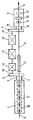
- This shows: a section of a rolling mill with a finishing mill, a cooling and compensation device and with a switchable finishing mill as a precision mill.
- the generic fine steel / wire mill generally consists of a preheating chamber in which the pre-block to be rolled out, usually a billet, is preheated before it is heated to rolling temperature in a pusher furnace, for example.
- the billet comes out of the pusher furnace after descaling the press water into a multi-stand roughing mill, in which the billet cross-section is reduced to a round cross-section.
- Crank cropping and chopping shears are usually installed after the roughing mill and are able to prepare the cropping end for the intermediate mill.
- the rolling core passes through the intermediate line, in which the cross section of the round rolled stock is further reduced in several passes. Subsequently, after a renewed cropping of the roll ends, the roll core enters the finishing roll block 1 shown schematically in FIG. 1.
- the finishing mill 1 has ten swirl-free stand cassettes in a 45 ° arrangement.
- the horizontal stand cassettes 16 are drawn perpendicular to the rolling core 5 in the schematic plan view and drawn out with a reinforced line.
- the vertical stand cassettes 17 are shown as opposing rolling rings.
- the finishing mill block 1 is connected to a transfer case 2, from which an output shaft 3 is laid to the horizontal stand cassettes and an output shaft 4 to the vertical stand cassettes.
- the section of the fine steel / wire mill shown also shows a two-stand roughing block 6, the vertical stand cassette 6 'and the horizontal stand cassette 6' 'being arranged at a 90 ° angle to one another.
- the finishing mill 1 and the finishing mill 6 are aligned with each other in the rolling line.
- the roughing block 6 is connected to a manual transmission 7, from which an output shaft 8 is guided to the horizontal stand cassette and an output shaft 9 to the vertical stand cassette.
- the input shafts 10, 11 of the transfer case 2 or of the manual transmission 7 are directly coupled to three DC motors 12 of the same power rating. The DC motors are used to drive the finishing block and the finishing block.
- a water box 13 for cooling the rolling stock and a compensation section 14 for temperature compensation of the rolling stock are provided between the transfer case 2 and the manual transmission 7.
- the roughing block 6 has a changeover gear 15 between the vertical stand cassette 6 'and the horizontal stand cassette 6''in order to be able to use the roughing block as a precision rolling stand if required.
- the gear ratio of the changeover gear 15 is approximately 1: 1.25 to 1: 1.15. If the roughing block is used as a precision roll stand, the calibration of the rolls of the discharge stand or the stand cassette 6 ′′ is adapted to the specified precision roll.
- a further water cooling section is optionally arranged, which was not shown in more detail, as well as a Stelmor system, a bundle forming chamber and a hook track for the cooled wire bundles that were prepared for dispatch.
- the wire is then passed through the water tank 13, cooled in it and then passed through the temperature compensation section 14.
- the temperature cooling and temperature compensation are controlled depending on the respective wire alloy and the desired quality profile. If necessary, a cooling / compensating arrangement of the finishing block 1 can be switched on.
- the wire then enters the roughing block 6 and is rolled out in the first vertical stand cassette in a standard pass to initially 5 mm in diameter.
- the rolling mill of the type specified here is made even more adaptable to the different rolled product products and rolled material qualities by switching the post-rolling block into a precision rolling stand according to the invention.
Landscapes
- Engineering & Computer Science (AREA)
- Mechanical Engineering (AREA)
- Metal Rolling (AREA)
- Reduction Rolling/Reduction Stand/Operation Of Reduction Machine (AREA)
Abstract
Description
Die Erfindung betrifft ein Verfahren zum Auswalzen von Draht bzw. von Walzgut mit Rundquerschnitt aus Edelstahl oder sonstigem Legierungsstahl in einer Hochleistungs Feinstahl/Draht-Straße mit jeweils mehrere Walzgerüste bzw. Walzeinheiten aufweisender Vorstraße, mindestens einer Zwischenstraße mit anschließender Fertigstraße, insbesondere als Fertigwalzblock, wobei dem Fertigwalzblock ein mindestens zwei-gerüstiger Nachwalzblock nachgeordnet ist und zwischen Fertigwalzblock und Nachwalzblock gegebenenfalls eine Kühlstrecke und/oder eine Temperaturausgleichsvorrichtung angeordnet ist. Die Erfindung betrifft auch eine Walzstraße zur Durchführung des Walzverfahrens.The invention relates to a method for rolling out wire or rolling stock with a round cross-section made of stainless steel or other alloy steel in a high-performance fine steel / wire mill, each with a plurality of roll stands or rolling units, a roughing mill, at least one intermediate mill with a subsequent finishing mill, in particular as a finishing mill block, whereby the finishing roll block is followed by an at least two-stand finishing roll block and, if appropriate, a cooling section and / or a temperature compensation device is arranged between the finish rolling block and the finish rolling block. The invention also relates to a rolling mill for carrying out the rolling process.
Moderne Hochleistungs Feinstahl/Drahtstraßen bestehen hinter der Ofenanlage zumeist aus einer Vorstraße, einer oder mehrerer Zwischenstraßen und aus einem Fertigwalzblock für das Walzgut. Die Walzgerüste in Vorstraße und Zwischenstraße sind robust gebaut und für hohe Walzansprüche ausgelegt. In der Vorstraße sind es im allgemeinen Einzelgerüste. In der Zwischenstraße sind es vorzugsweise Kompaktgerüste mit einer Horizontal/Vertikalanordnung der Walzen. Als Fertigwalzblock versteht man Walzmaschinen, die aus mehreren, meist sechs bis zehn, wechselweise um 90° gegeneinander versetzten Walzeinheiten bestehen, die in Walzlinie dicht hintereinander in einer Kassette untergebracht sind und die als Walzeinheiten von einem Antrieb über ein Verteilergetriebe direkt und gemeinsam angetrieben werden.Modern high-performance fine steel / wire mills usually consist of a roughing mill, one or more intermediate mills and a finishing block for the rolling stock behind the furnace system. The mill stands in the Vorstrasse and Zwischenstrasse are robustly built and designed for high rolling demands. In the Vorstraße there are generally single scaffolds. In the intermediate line there are preferably compact stands with a horizontal / vertical arrangement of the rollers. A finishing mill is understood to mean rolling machines that consist of several, usually six to ten, alternately offset 90 ° rolling units, which are housed in a cassette in the rolling line and are driven directly and together by a drive via a transfer case.
Nach dem Fertigwalzblock folgt eine Wasserkühlstrecke mit integrierter Temperaturausgleichsstrecke für das Walzgut. In Abhängigkeit von Abmessung und Qualität des Walzgutes lassen sich die Kühlzonen so ansteuern, daß auch bei maximaler Walzgeschwindigkeit das geforderte Temperaturprofil im Walzgut erreicht wird. Hinter der Wasserkühlstrecke wird das Walzgut bspw. auf einer Stelmor-Anlage luftgekühlt. Am Ende der Stelmor-Anlage befindet sich eine verstellbare Fallstufe mit anschließendem Kettentransport. Über den Kettentransport laufen die Drahtwindungen in die Bundbildekammern ein. Die gebildeten Bunde werden über eine Kippstuhlentladestation auf eine Hakenbahn aufgelegt und gehen von dort in die Bindeanlagen und den Versand.After the finish rolling block, there is a water cooling section with an integrated temperature compensation section for the rolling stock. Depending on the size and quality of the rolling stock, the cooling zones can be controlled so that the required temperature profile in the rolling stock is achieved even at maximum rolling speed. Behind the water cooling section, the rolling stock is air-cooled, for example, on a Stelmor system. At the end of the Stelmor system there is an adjustable drop step with subsequent chain transport. The wire windings enter the bundle forming chambers via the chain transport. The bundles formed are placed on a hook conveyor via a tipping chair unloading station and from there go into the binding machines and the dispatch.
In einer nicht veröffentlichten Patentanmeldung wird zur Erhöhung der Leistungsfähigkeit, insbesondere bestehender Feinstahl/Drahtstraßen, die gegebenenfalls schon im technischen Grenzbereich betrieben werden, vorgeschlagen, daß dem Fertigwalzblock ein weiterer, mindestens zweigerüstiger Nachwalzblock nachzuordnen ist, wobei zwischen dem Fertigwalzblock und dem Nachwalzblock eine temperierende Kühl- und/oder Ausgleichsvorrichtung für das Walzgut zwischengeschaltet ist. Mit dieser Maßnahme kann die Gesamt-Stichabnahme bestehender Walzstraßen erhöht werden und es können dünnere Fertigabmessungen für das Walzgut erzeugt werden. Auch kann die Endwalzgeschwindigkeit bei ungeändertem Geschwindigkeitsniveau der Straße gesteigert werden. Ferner kann das Gefüge im Walzgut durch gezielte Kühlung vor den letzten beiden Stichen im Nachwalzblock beeinflußt werden.In an unpublished patent application, in order to increase the performance, in particular existing fine steel / wire mills, which may already be operated in the technical limit range, it is proposed that the finishing block be followed by a further, at least two-stand finishing block, with a tempering cooling between the finishing block and the finishing block - And / or compensation device for the rolling stock is interposed. With this measure, the total pass reduction of existing rolling mills can be increased and thinner finished dimensions can be generated for the rolling stock. The final rolling speed can also be increased if the speed level of the road remains unchanged. Furthermore, the structure in the rolling stock can be influenced by targeted cooling before the last two passes in the roughing block.
Die Aufgabe der vorliegenden Erfindung besteht darin, die Walzstraße der eingangs genannten Gattung weiter auszugestalten, um bei hohem Leistungsniveau der Straße auch engste Drahttoleranzen gewährleisten zu können.The object of the present invention is to further develop the rolling mill of the type mentioned at the outset in order to be able to guarantee even the tightest wire tolerances with a high performance level of the mill.
Diese Aufgabe wird gemäß der Erfindung dadurch gelöst, daß das Walzgut in dem Nachwalzblock mit einer gegenüber den in dem Fertigwalzblock durchgeführten Abnahmestichen deutlich geringeren Stichabnahme ausgewalzt wird. Der Nachwalzblock wird also als Präzisionswalzblock benutzt, um die Oberflächengüte des Walzgutes zu verbessern und die Walzguttoleranzen weiter einzuengen. In Verbindung mit der möglichen Temperatursteuerung des Walzgutes in der Kühl- und Ausgleichsstrecke vor dem Präzisionswalzen können die Walzguteigenschaften und die Oberfläche des Walzgutes in weitem Rahmen den jeweiligen Produktanforderungen schnell und sicher angepaßt werden.This object is achieved according to the invention in that the rolling stock is rolled out in the re-rolling block with a significantly lower pass reduction compared to the take-off passes performed in the finishing roll block. The roughing block is therefore used as a precision rolling block in order to improve the surface quality of the rolling stock and to further narrow the rolling stock tolerances. In connection with the possible temperature control of the rolling stock in the cooling and compensation line before precision rolling, the rolling stock properties and the surface of the rolling stock can be quickly and safely adapted to the respective product requirements.
Insbesondere bei einem zweigerüstigen Nachwalzblock ist es zweckmäßig, wenn das Walzgut in dem Auslaufgerüst des Nachwalzblocks mit einer gegenüber der zuvor erfolgten Abnahme geringeren Stichabnahme ausgewalzt wird. Als vorteilhaft hat sich herausgestellt, wenn die Stichabnahme im Auslaufgerüst etwa 5 % - 15 % beträgt.In the case of a two-stand roughing block in particular, it is expedient if the rolling stock is rolled out in the run-out stand of the roughing block with a smaller pass reduction compared to the previous acceptance. It has proven to be advantageous if the stitch reduction in the discharge stand is approximately 5% - 15%.
Das Walzwerk zur Durchführung des erfindungsgemäßen Walzverfahrens für Draht oder Walzgut mit Rundquerschnitt zeichnet sich dadurch aus, daß der Nachwalzblock ein Schaltgetriebe zu dessen Umschaltung auf ein Dressier- bzw. Präzisionswalzblock aufweist. Schaltgetriebe in bisher geläufigen Anordnungen von Walzwerken zur Reduzierung der Abnahmeverhältnisse mögen an sich bekannt sein. Mit der vorliegenden Maßnahme hat dies aber nichts zu tun, da der Einsatz eines Nachwalzblocks hinter dem Fertigwalzblock einer Walzstraße unbekannt blieb. Zur Bereicherung der bekannten Walzwerkstechnik ermöglicht die hier vorgeschlagene Umschaltung des Nachwalzblocks bzw. bestimmter Gerüstkassetten des Nachwalzblocks die Herstellung engster Walzguttoleranzen und die Anpassung, insbesondere bestehender Walzstraßen an eine weite Produktpalette.The rolling mill for carrying out the rolling method according to the invention for wire or rolling stock with a round cross-section is characterized in that the post-rolling block has a manual transmission for switching it over to a skin pass or precision rolling block. Manual transmissions in hitherto familiar arrangements of rolling mills to reduce the acceptance ratios may be known per se. However, this has nothing to do with the present measure, since the use of a roughing block behind the finishing block of a rolling mill remained unknown. To enrich the known rolling mill technology, the switchover of the roughing block or certain framework cassettes of the roughing block proposed here enables the production of the narrowest tolerances of the rolling stock and the adaptation, in particular of existing rolling mills, to a wide range of products.
In vorteilhafter Ausgestaltung des Walzwerks kann das Schaltgetriebe vor dem Nachwalzblock angeordnet sein. Es ist jedoch auch zweckmäßig, daß das Schaltgetriebe zwischen den einzelnen Gerüsten des Nachwalzblocks vorzugsweise vor dessen Auslaufgerüst angeordnet ist.In an advantageous embodiment of the rolling mill, the gearbox can be arranged in front of the roughing block. However, it is also expedient that the gearbox is preferably arranged between the individual stands of the roughing block before its outlet stand.
Da in dem auf ein Präzisionswalzgerüst umgeschalteten Nachwalzblock nur noch eine geringe Walzgutabnahme bspw. von 5 bis 15 % erfolgt, ist das Übersetzungsverhältnis des Schaltgetriebes in einem Bereich von 1:1,25 bis 1:1,15 ausgelegt. Ferner ist es vorteilhaft, wenn die Kalibrierung der Walzen im Nachwalzblock der Präzisionswalzung anpaßbar sind.Since there is only a small decrease in rolling stock, for example of 5 to 15%, in the re-rolling block switched to a precision rolling stand, the gear ratio of the manual transmission is designed in a range from 1: 1.25 to 1: 1.15. It is also advantageous if the calibration of the rolls in the finishing block can be adapted to the precision rolling.
Die Erfindung wird nachfolgend anhand eines Ausführungsbeispiels für eine Feinstahl/Drahtstraße beschrieben. Dieses zeigt:
einen Ausschnitt aus einer Walzstraße mit einem Fertigwalzblock, einer Kühl- und Ausgleichsvorrichtung und mit einem schaltbaren Nachwalzblock als Präzisionswalzgerüst.The invention is described below using an exemplary embodiment for a fine steel / wire mill. This shows:
a section of a rolling mill with a finishing mill, a cooling and compensation device and with a switchable finishing mill as a precision mill.
Die gattungsgemäße Feinstahl/Drahtstraße besteht in der Regel aus einer Vorwärmkammer, in der der auszuwalzende Vorblock, zumeist ein Knüppel, vorgewärmt wird, bevor dieser bspw. in einem Stoßofen auf Walztemperatur aufgeheizt wird. Der Knüppel gelangt aus dem Stoßofen nach einer Preßwasserentzunderung in eine mehrgerüstige Vorstraße, in welcher der Knüppelquerschnitt auf einen runden Querschnitt reduziert wird. Nach der Vorstraße ist gewöhnlich eine Kurbel-Schopf- und Häckselschere installiert, die in der Lage ist, das Schopfende für die Zwischenstraße vorzubereiten. Die Walzader durchläuft die Zwischenstraße, in welcher der Querschnitt des runden Walzgutes in mehreren Stichen weiter reduziert wird. Anschließend gelangt die Walzader nach einem erneuten Schopfen der Walzenden in den in der Fig. 1 schematisch dargestellten Fertigwalzblock 1.The generic fine steel / wire mill generally consists of a preheating chamber in which the pre-block to be rolled out, usually a billet, is preheated before it is heated to rolling temperature in a pusher furnace, for example. The billet comes out of the pusher furnace after descaling the press water into a multi-stand roughing mill, in which the billet cross-section is reduced to a round cross-section. Crank cropping and chopping shears are usually installed after the roughing mill and are able to prepare the cropping end for the intermediate mill. The rolling core passes through the intermediate line, in which the cross section of the round rolled stock is further reduced in several passes. Subsequently, after a renewed cropping of the roll ends, the roll core enters the finishing roll block 1 shown schematically in FIG. 1.
Der Fertigwalzblock 1 besitzt zehn drallfreie Gerüstkassetten in 45°-Anordnung. Die horizontalen Gerüstkassetten 16 sind in der schematischen Draufsicht senkrecht zur Walzader 5 gezeichnet und mit einem verstärkten Strich ausgezogen. Die vertikalen Gerüstkassetten 17 sind als gegenüberliegende Walzringe dargestellt. Der Fertigwalzblock 1 ist mit einem Verteilergetriebe 2 verbunden, von dem eine Abtriebswelle 3 zu den horizontalen Gerüstkassetten und eine Abtriebswelle 4 zu den vertikalen Gerüstkassetten verlegt ist.The finishing mill 1 has ten swirl-free stand cassettes in a 45 ° arrangement. The
Der dargestellte Ausschnitt der Feinstahl/Drahtstraße zeigt außerdem einen zweigerüstigen Nachwalzblock 6, wobei die vertikale Gerüstkassette 6' und die horizontale Gerüstkassette 6'' in einem 90°-Winkel zueinander angeordnet sind. Der Fertigwalzblock 1 und der Nachwalzblock 6 sind in Walzlinie zueinander ausgerichtet. Der Nachwalzblock 6 ist mit einem Schaltgetriebe 7 verbunden, von welchem eine Abtriebswelle 8 zu der horizontalen Gerüstkassette und eine Abtriebswelle 9 zu der vertikalen Gerüstkassette geführt ist. Die Eingangswellen 10, 11 des Verteilergetriebes 2 bzw. des Schaltgetriebes 7 sind direkt mit drei leistungsmäßig gleich stark ausgelegten Gleichstrommotoren 12 gekoppelt. Die Gleichstrommotoren dienen dem Antrieb des Fertigwalzblocks und dem Antrieb des Nachwalzblocks. Zwischen dem Verteilergetriebe 2 und dem Schaltgetriebe 7 ist ein Wasserkasten 13 zur Kühlung des Walzgutes und eine Ausgleichsstrecke 14 zum Temperaturausgleich des Walzgutes vorgesehen.The section of the fine steel / wire mill shown also shows a two-stand roughing block 6, the vertical stand cassette 6 'and the horizontal stand cassette 6' 'being arranged at a 90 ° angle to one another. The finishing mill 1 and the finishing mill 6 are aligned with each other in the rolling line. The roughing block 6 is connected to a
Der Nachwalzblock 6 weist zwischen der vertikalen Gerüstkassette 6' und der horizontalen Gerüstkassette 6'' ein Umschaltgetriebe 15 auf, um den Nachwalzblock bei Bedarf als Präzisionswalzgerüst einsetzen zu können. Das Übersetzungsverhältnis des Umschaltgetriebes 15 beträgt etwa 1:1,25 bis 1:1,15. Wird der Nachwalzblock als Präzisionswalzgerüst benutzt, so wird die Kalibrierung der Walzen des Auslaufgerüstes bzw. der Gerüstkassette 6'' der vorgegebenen Präzisionswalzung angepaßt.The roughing block 6 has a changeover gear 15 between the vertical stand cassette 6 'and the horizontal stand cassette 6''in order to be able to use the roughing block as a precision rolling stand if required. The gear ratio of the changeover gear 15 is approximately 1: 1.25 to 1: 1.15. If the roughing block is used as a precision roll stand, the calibration of the rolls of the discharge stand or the stand cassette 6 ″ is adapted to the specified precision roll.
Hinter dem Nachwalzblock ist - was nicht näher dargestellt wurde gegebenenfalls eine weitere Wasserkühlstrecke angeordnet sowie eine Stelmor-Anlage, eine Bundbildekammer sowie eine Hakenbahn für die abgekühlten und zum Versand vorbereiteten Drahtbunde.Behind the re-rolling block, a further water cooling section is optionally arranged, which was not shown in more detail, as well as a Stelmor system, a bundle forming chamber and a hook track for the cooled wire bundles that were prepared for dispatch.
Der vorgewalzte und geschopfte Draht aus der nicht dargestellten Zwischenstraße tritt in den Fertigwalzblock 1 ein und wird in dessen zehn Gerüstkassetten drallfrei auf bspw. 5,5 mm Durchmesser bei einer Endwalzgeschwindigkeit von etwa 85 m/sec reduziert. Anschließend wird der Draht durch den Wasserkasten 13 geführt, in diesem abgekühlt und danach durch die Temperaturausgleichsstrecke 14 geführt. Die Regelung der Temperaturabkühlung und des Temperaturausgleichs erfolgt in Abhängigkeit von der jeweiligen Drahtlegierung und von dem gewünschten Qualitätsprofil. Gegebenenfalls kann eine Kühl/Ausgleichsanordnung des Fertigwalzblocks 1 zugeschaltet werden. Anschließend gelangt der Draht in den Nachwalzblock 6 und wird in der ersten vertikalen Gerüstkassette in einem Standardstich auf zunächst 5 mm Durchmesser ausgewalzt. Danach gelangt er in die horizontale Gerüstkassette 6'' und wird in diesem Auslaufgerüst mit einer deutlich geringeren Stichabnahme ausgewalzt, d.h. der Draht erfährt in dem Auslaufgerüst nur noch eine Durchmesserabnahme von etwa 5 bis 15 %. Bei entsprechend angepaßter Kalibrierung der Walzringe in dem Auslaufgerüst 6'' des Nachwalzblocks werden auf diese Weise engste Drahttoleranzen erzielt bei unveränderte hohem Leistungsniveau des Walzwerks.The pre-rolled and cropped wire from the intermediate line, not shown, enters the finishing mill 1 and is reduced in a twist-free manner in its ten stand cassettes to, for example, 5.5 mm in diameter at a final rolling speed of about 85 m / sec. The wire is then passed through the
Das Walzwerk der hier bestimmten Gattung wird durch die erfindungsgemäße Umschaltung des Nachwalzblocks in ein Präzisionswalzgerüst noch anpassungsfähiger an die unterschiedlichen Walzgutprodukte und Walzgutqualitäten.The rolling mill of the type specified here is made even more adaptable to the different rolled product products and rolled material qualities by switching the post-rolling block into a precision rolling stand according to the invention.
- 11
- FertigwalzblockFinishing mill
- 22nd
- VerteilergetriebeTransfer case
- 33rd
- AbtriebswelleOutput shaft
- 44th
- AbtriebswelleOutput shaft
- 55
- Walzader/WalzgutRolling wire / rolling stock
- 66
- NachwalzblockRoughing block
- 6'6 '
- vertikale Gerüstkassettevertical scaffold cassette
- 6''6 ''
- horizontale Gerüstkassettehorizontal scaffold cassette
- 77
- SchaltgetriebeManual transmission
- 88th
- AbtriebswelleOutput shaft
- 99
- AbtriebswelleOutput shaft
- 1010th
- Eingangswelle VerteilergetriebeInput shaft transfer case
- 1111
- Eingangswelle SchaltgetriebeInput shaft manual transmission
- 1212
- GleichstrommotorDC motor
- 1313
- WasserkastenWater tank
- 1414
- AusgleichsstreckeCompensation distance
- 1515
- UmschaltgetriebeReverse gear
- 1616
- horizontale Gerüstkassettehorizontal scaffold cassette
- 1717th
- vertikale Gerüstkassettevertical scaffold cassette
Claims (8)
dadurch gekennzeichnet,
daß das Walzgut (5) in dem Nachwalzblock (6) mit einer gegenüber den in dem Fertigwalzblock (1) durchgeführten Abnahmestichen deutlich geringeren Stichabnahme ausgewalzt wird.Process for rolling out wire or rolled material with a round cross-section made of stainless steel or other alloy steel in a high-performance fine steel / wire mill with in each case several roughing stands or rolling units comprising a roughing mill, at least one intermediate mill with a subsequent finishing mill, in particular as a finishing mill block, the finishing mill block having an at least two-stand mill Post-rolling block, and a cooling section and / or temperature compensation device is optionally arranged between the finishing roll block and the post-rolling block,
characterized,
that the rolling stock (5) is rolled out in the roughing block (6) with a significantly lower pass reduction compared to the acceptance passes performed in the finishing roll block (1).
dadurch gekennzeichnet,
daß das Walzgut (5) in dem Auslaufgerüst (6'') des Nachwalzblocks (6) mit einer gegenüber der zuvor erfolgten Abnahme deutlich geringeren Stichabnahme ausgewalzt wird.Method according to claim 1,
characterized,
that the rolling stock (5) is rolled out in the discharge stand (6 '') of the finishing block (6) with a significantly lower pass reduction compared to the previous decrease.
dadurch gekennzeichnet,
daß die Stichabnahme im Auslaufgerüst (6'') etwa 5 % bis 15 % beträgt.The method of claim 1 or 2,
characterized,
that the stitch decrease in the discharge stand (6 '') is about 5% to 15%.
dadurch gekennzeichnet,
daß der Nachwalzblock (6) ein Umschaltgetriebe (15) zu dessen Umschaltung auf ein Dressier- bzw. Präzisionswalzblock aufweist.Rolling mill for carrying out the rolling process for wire or rolling stock with a round cross-section according to at least one of Claims 1 to 3,
characterized,
that the roughing block (6) has a changeover gear (15) for switching it over to a skin pass or precision roll block.
dadurch gekennzeichnet,
daß das Umschaltgetriebe (15) vor dem Nachwalzblock (6) angeordnet ist.Device according to claim 4,
characterized,
that the changeover gear (15) is arranged in front of the roughing block (6).
dadurch gekennzeichnet,
daß das Umschaltgetriebe (15) zwischen den einzelnen Gerüsten (6', 6'') des Nachwalzblocks (6), vorzugsweise vor dessen Auslaufgerüst (6'') angeordnet ist (Fig. 1).Device according to claim 4,
characterized,
that the changeover gear (15) between the individual stands (6 ', 6'') of the roughing block (6), preferably in front of the outlet stand (6'') is arranged (Fig. 1).
dadurch gekennzeichnet,
daß das Übersetzungsverhältnis des Umschaltgetriebes (15) im Bereich von 1:1,25 bis 1:1,15 ausgelegt ist.Device according to at least one of claims 4 to 6,
characterized,
that the gear ratio of the changeover gear (15) is designed in the range from 1: 1.25 to 1: 1.15.
dadurch gekennzeichnet,
daß die Kalibrierung der Walzen im Nachwalzblock (6) der Präzisionswalzung anpaßbar ist.Rolling mill according to at least one of Claims 4 to 7,
characterized,
that the calibration of the rolls in the roughing block (6) of the precision rolling is adaptable.
Applications Claiming Priority (2)
| Application Number | Priority Date | Filing Date | Title |
|---|---|---|---|
| DE4207298A DE4207298A1 (en) | 1992-03-07 | 1992-03-07 | METHOD AND ROLLING MILL FOR PRECISION ROLLING OF WIRE OR FROM ROLLING GOODS WITH A ROUND SECTION |
| DE4207298 | 1992-03-07 |
Publications (2)
| Publication Number | Publication Date |
|---|---|
| EP0560115A1 true EP0560115A1 (en) | 1993-09-15 |
| EP0560115B1 EP0560115B1 (en) | 1997-06-18 |
Family
ID=6453504
Family Applications (1)
| Application Number | Title | Priority Date | Filing Date |
|---|---|---|---|
| EP93102809A Expired - Lifetime EP0560115B1 (en) | 1992-03-07 | 1993-02-24 | Method and rolling mill for precision rolling wire or stock having a circular cross-section |
Country Status (5)
| Country | Link |
|---|---|
| US (1) | US5682785A (en) |
| EP (1) | EP0560115B1 (en) |
| JP (1) | JP3293933B2 (en) |
| AT (1) | ATE154527T1 (en) |
| DE (2) | DE4207298A1 (en) |
Cited By (6)
| Publication number | Priority date | Publication date | Assignee | Title |
|---|---|---|---|---|
| EP0694345A1 (en) * | 1994-07-29 | 1996-01-31 | Sms Schloemann-Siemag Aktiengesellschaft | Small section mill, in particular wire mill |
| EP0845310A1 (en) * | 1996-11-27 | 1998-06-03 | Sms Schloemann-Siemag Aktiengesellschaft | Wire cooling |
| WO1999025499A1 (en) * | 1997-11-14 | 1999-05-27 | Voest-Alpine Industrieanlagenbau Gmbh | Precision-rolling method |
| US6327885B1 (en) | 1999-07-26 | 2001-12-11 | Voest-Alpine Industrieanlagenbau Gmbh | Rolling-mill installation |
| WO2006050680A1 (en) * | 2004-10-02 | 2006-05-18 | C.D. Wälzholz-Brockhaus GmbH | Method and device for shaping wire-shaped and rod-shaped starting materials close to the gauge block, and correspondingly produced flat profiled element |
| WO2006097317A1 (en) * | 2005-03-16 | 2006-09-21 | Siemens Vai Metals Technologies S.R.L. | Rolling monoblock with intercooling |
Families Citing this family (1)
| Publication number | Priority date | Publication date | Assignee | Title |
|---|---|---|---|---|
| US6185972B1 (en) | 1999-03-11 | 2001-02-13 | Morgan Construction Company | Rolling mill finishing section |
Citations (6)
| Publication number | Priority date | Publication date | Assignee | Title |
|---|---|---|---|---|
| DE1602180A1 (en) * | 1967-08-23 | 1970-02-26 | Suedwestfalen Ag Stahlwerke | Recalibration device for rolling stock |
| US4024746A (en) * | 1975-01-28 | 1977-05-24 | Demag Aktiengesellschaft | Stand gearing arrangement for the rolls of a continuous rolling mill |
| EP0313930A2 (en) * | 1987-10-30 | 1989-05-03 | Daido Tokushuko Kabushiki Kaisha | Sizing mill and method of rolling a round bar material |
| EP0340505A2 (en) * | 1988-05-05 | 1989-11-08 | Sms Schloemann-Siemag Aktiengesellschaft | Operating process and roll train for continuously rolling a sectional bar to a finished profile section with given accurate dimensions |
| EP0479749A1 (en) * | 1990-10-03 | 1992-04-08 | Nippon Steel Corporation | Sizing-rolling method for continuous length sections, rolling mill driving mechanism, roll depressing mechanism and roll fixing mechanism |
| EP0512735B1 (en) * | 1991-05-06 | 1995-04-12 | Morgan Construction Company | Method for continuously hot rolling of ferrous long products |
Family Cites Families (12)
| Publication number | Priority date | Publication date | Assignee | Title |
|---|---|---|---|---|
| GB216280A (en) * | 1923-04-09 | 1924-05-29 | Arthur Claud Page | Improvements in or relating to shop blinds and the like |
| US1931912A (en) * | 1930-04-08 | 1933-10-24 | Aluminum Co Of America | Method of forming aluminum |
| BE541872A (en) * | 1954-10-15 | |||
| DE2437684C2 (en) * | 1974-08-05 | 1982-09-02 | SMS Schloemann-Siemag AG, 4000 Düsseldorf | Rolling mill for the production of wire and ribbed steel |
| US3992915A (en) * | 1975-04-21 | 1976-11-23 | Birdsboro Corporation | Rolling mill |
| DE2920398A1 (en) * | 1979-05-19 | 1980-11-20 | Kocks Technik | ROLLING BLOCK FOR HOT ROLLING WIRE OR BARS |
| IT7922943V0 (en) * | 1979-10-23 | 1979-10-23 | Properzi Giulio | CONTINUOUS ROLLING MACHINE FOR ROD OR METAL WIRE WITH MORE IN LINE ROLLING UNITS. |
| US4527408A (en) * | 1983-10-31 | 1985-07-09 | Morgan Construction Company | Method and Apparatus for cooling and handling hot rolled steel rod in direct sequence with a high speed rolling operation |
| JPS60152302A (en) * | 1984-01-19 | 1985-08-10 | Daido Steel Co Ltd | Method for precision rolling of steel bar |
| JPS6343702A (en) * | 1986-08-08 | 1988-02-24 | Nippon Steel Corp | Sizing rolling method for wire rod |
| ATE101065T1 (en) * | 1986-10-20 | 1994-02-15 | Schloemann Siemag Ag | FINE OR MEDIUM STEEL LINE. |
| DE3830101A1 (en) * | 1988-09-05 | 1990-03-15 | Schloemann Siemag Ag | METHOD FOR OPERATING A STEEL ROLLING MILL WITH A REFRIGERATION LINE ARRANGED ON A ROLLING LINE FOR THERMOMECHANICAL FINISHED ROLLS AND ROLLING STEEL ROLLING MILL FOR IMPLEMENTING THE METHOD |
-
1992
- 1992-03-07 DE DE4207298A patent/DE4207298A1/en not_active Withdrawn
-
1993
- 1993-02-24 EP EP93102809A patent/EP0560115B1/en not_active Expired - Lifetime
- 1993-02-24 AT AT93102809T patent/ATE154527T1/en not_active IP Right Cessation
- 1993-02-24 DE DE59306757T patent/DE59306757D1/en not_active Expired - Fee Related
- 1993-03-05 JP JP04550093A patent/JP3293933B2/en not_active Ceased
-
1996
- 1996-05-29 US US08/654,813 patent/US5682785A/en not_active Expired - Fee Related
Patent Citations (6)
| Publication number | Priority date | Publication date | Assignee | Title |
|---|---|---|---|---|
| DE1602180A1 (en) * | 1967-08-23 | 1970-02-26 | Suedwestfalen Ag Stahlwerke | Recalibration device for rolling stock |
| US4024746A (en) * | 1975-01-28 | 1977-05-24 | Demag Aktiengesellschaft | Stand gearing arrangement for the rolls of a continuous rolling mill |
| EP0313930A2 (en) * | 1987-10-30 | 1989-05-03 | Daido Tokushuko Kabushiki Kaisha | Sizing mill and method of rolling a round bar material |
| EP0340505A2 (en) * | 1988-05-05 | 1989-11-08 | Sms Schloemann-Siemag Aktiengesellschaft | Operating process and roll train for continuously rolling a sectional bar to a finished profile section with given accurate dimensions |
| EP0479749A1 (en) * | 1990-10-03 | 1992-04-08 | Nippon Steel Corporation | Sizing-rolling method for continuous length sections, rolling mill driving mechanism, roll depressing mechanism and roll fixing mechanism |
| EP0512735B1 (en) * | 1991-05-06 | 1995-04-12 | Morgan Construction Company | Method for continuously hot rolling of ferrous long products |
Non-Patent Citations (2)
| Title |
|---|
| PATENT ABSTRACTS OF JAPAN vol. 9, no. 316 (M-438)12. Dezember 1985 & JP-A-60 152 302 ( DAIDO TOKUSHUKO ) 10. August 1985 * |
| STAHL UND EISEN. Bd. 110, Nr. 6, 14. Juni 1990, DUSSELDORF DE Seiten 59 - 64 W.KR[MER ET AL.: 'Hochpr{zisionswalzen von Stabstahl auf der Feinstahl- und Drahtstrasse der Moos Stahl AG (Luzern/Schweiz)' * |
Cited By (9)
| Publication number | Priority date | Publication date | Assignee | Title |
|---|---|---|---|---|
| EP0694345A1 (en) * | 1994-07-29 | 1996-01-31 | Sms Schloemann-Siemag Aktiengesellschaft | Small section mill, in particular wire mill |
| US5666843A (en) * | 1994-07-29 | 1997-09-16 | Sms Schloemann-Siemag Aktiengesellschaft | Light section rolling mill particularly wire rolling mill |
| EP0845310A1 (en) * | 1996-11-27 | 1998-06-03 | Sms Schloemann-Siemag Aktiengesellschaft | Wire cooling |
| US5907967A (en) * | 1996-11-27 | 1999-06-01 | Sms Schloemann-Siemag Ag | Wire rod cooling |
| WO1999025499A1 (en) * | 1997-11-14 | 1999-05-27 | Voest-Alpine Industrieanlagenbau Gmbh | Precision-rolling method |
| US6216517B1 (en) | 1997-11-14 | 2001-04-17 | Voest Alpine Industieanlagenbau Gmbh | Precision-rolling process |
| US6327885B1 (en) | 1999-07-26 | 2001-12-11 | Voest-Alpine Industrieanlagenbau Gmbh | Rolling-mill installation |
| WO2006050680A1 (en) * | 2004-10-02 | 2006-05-18 | C.D. Wälzholz-Brockhaus GmbH | Method and device for shaping wire-shaped and rod-shaped starting materials close to the gauge block, and correspondingly produced flat profiled element |
| WO2006097317A1 (en) * | 2005-03-16 | 2006-09-21 | Siemens Vai Metals Technologies S.R.L. | Rolling monoblock with intercooling |
Also Published As
| Publication number | Publication date |
|---|---|
| EP0560115B1 (en) | 1997-06-18 |
| JPH05337502A (en) | 1993-12-21 |
| DE59306757D1 (en) | 1997-07-24 |
| DE4207298A1 (en) | 1993-09-09 |
| ATE154527T1 (en) | 1997-07-15 |
| JP3293933B2 (en) | 2002-06-17 |
| US5682785A (en) | 1997-11-04 |
Similar Documents
| Publication | Publication Date | Title |
|---|---|---|
| DE69411971T3 (en) | Hot rolling mill for steel sheet and rolling process | |
| EP0256409B2 (en) | Method of producing sections | |
| EP0266564B1 (en) | Strip casting installation with a following multiple stand continuous rolling mill | |
| EP0368048B1 (en) | Method and device for manufacturing hot-rolled steel strip | |
| DE2256024A1 (en) | PROCESS FOR ROLLING HOT METAL WORKS | |
| EP0307606B1 (en) | Compact rolling mill train and method for rolling sections | |
| EP0818250B1 (en) | Method for rolling rails from preliminary sections | |
| EP1519798B1 (en) | Method and casting roller plant for the semi-endless or endless rolling by casting of a metal in particular a steel strip which may be transversely separated as required after solidification | |
| EP0761326A1 (en) | Installation for producing hot rolled thin strip | |
| DE4041206C2 (en) | Process and plant for the production of hot-rolled steel strip, in particular for stainless steels from continuously cast primary material | |
| DE2437684C2 (en) | Rolling mill for the production of wire and ribbed steel | |
| DE4009861C2 (en) | Process for the production of hot-rolled bar material such as fine steel or wire and plant for carrying out the process | |
| DE19935647C2 (en) | Process for rolling heated metallic material and plant for carrying out the process | |
| EP0560093B1 (en) | Small section-/wire rod mill | |
| EP0560115B1 (en) | Method and rolling mill for precision rolling wire or stock having a circular cross-section | |
| EP1675693B1 (en) | Rolling mill for hot-rolling metal, in particular, aluminium in addition to hot-rolling method | |
| EP1463591B1 (en) | Method and rolling stand for producing rods, bar stock or seamless tubes | |
| DE4009860C2 (en) | Process and plant for the production of hot-rolled steel strip, in particular for stainless steels, from strip-shaped continuous material | |
| DE1427875A1 (en) | Rolling mill for rolling and method for producing profiles, such as double T-beams or the like. with thin wall thickness | |
| DE10261632B4 (en) | Process and rolling plant for the production of wire, bars or seamless tubes | |
| EP0845310B1 (en) | Wire cooling | |
| DE2659318A1 (en) | PROCESS FOR ROLLING ROUND STEEL | |
| EP1107834A1 (en) | Method and device for producing hot-rolled wide strip, notably from thin slabs | |
| EP1059125A2 (en) | Method for the manufacture of metal strip | |
| DE10025080A1 (en) | Method of making metal tape |
Legal Events
| Date | Code | Title | Description |
|---|---|---|---|
| PUAI | Public reference made under article 153(3) epc to a published international application that has entered the european phase |
Free format text: ORIGINAL CODE: 0009012 |
|
| 17P | Request for examination filed |
Effective date: 19930308 |
|
| AK | Designated contracting states |
Kind code of ref document: A1 Designated state(s): AT DE FR GB IT SE |
|
| 17Q | First examination report despatched |
Effective date: 19941108 |
|
| GRAG | Despatch of communication of intention to grant |
Free format text: ORIGINAL CODE: EPIDOS AGRA |
|
| GRAH | Despatch of communication of intention to grant a patent |
Free format text: ORIGINAL CODE: EPIDOS IGRA |
|
| GRAH | Despatch of communication of intention to grant a patent |
Free format text: ORIGINAL CODE: EPIDOS IGRA |
|
| GRAA | (expected) grant |
Free format text: ORIGINAL CODE: 0009210 |
|
| AK | Designated contracting states |
Kind code of ref document: B1 Designated state(s): AT DE FR GB IT SE |
|
| PG25 | Lapsed in a contracting state [announced via postgrant information from national office to epo] |
Ref country code: GB Effective date: 19970618 Ref country code: FR Effective date: 19970618 |
|
| REF | Corresponds to: |
Ref document number: 154527 Country of ref document: AT Date of ref document: 19970715 Kind code of ref document: T |
|
| REF | Corresponds to: |
Ref document number: 59306757 Country of ref document: DE Date of ref document: 19970724 |
|
| ITF | It: translation for a ep patent filed |
Owner name: STUDIO JAUMANN |
|
| EN | Fr: translation not filed | ||
| GBV | Gb: ep patent (uk) treated as always having been void in accordance with gb section 77(7)/1977 [no translation filed] |
Effective date: 19970618 |
|
| PLBQ | Unpublished change to opponent data |
Free format text: ORIGINAL CODE: EPIDOS OPPO |
|
| PLBI | Opposition filed |
Free format text: ORIGINAL CODE: 0009260 |
|
| PLBF | Reply of patent proprietor to notice(s) of opposition |
Free format text: ORIGINAL CODE: EPIDOS OBSO |
|
| 26 | Opposition filed |
Opponent name: MORGAN CONSTRUCTION COMPANY Effective date: 19980318 |
|
| PLBF | Reply of patent proprietor to notice(s) of opposition |
Free format text: ORIGINAL CODE: EPIDOS OBSO |
|
| PLBQ | Unpublished change to opponent data |
Free format text: ORIGINAL CODE: EPIDOS OPPO |
|
| PLAB | Opposition data, opponent's data or that of the opponent's representative modified |
Free format text: ORIGINAL CODE: 0009299OPPO |
|
| R26 | Opposition filed (corrected) |
Opponent name: MORGAN CONSTRUCTION COMPANY Effective date: 19980318 |
|
| RAP2 | Party data changed (patent owner data changed or rights of a patent transferred) |
Owner name: SMS DEMAG AG |
|
| PLBO | Opposition rejected |
Free format text: ORIGINAL CODE: EPIDOS REJO |
|
| PLBO | Opposition rejected |
Free format text: ORIGINAL CODE: EPIDOS REJO |
|
| APAC | Appeal dossier modified |
Free format text: ORIGINAL CODE: EPIDOS NOAPO |
|
| PLBQ | Unpublished change to opponent data |
Free format text: ORIGINAL CODE: EPIDOS OPPO |
|
| PLAB | Opposition data, opponent's data or that of the opponent's representative modified |
Free format text: ORIGINAL CODE: 0009299OPPO |
|
| R26 | Opposition filed (corrected) |
Opponent name: MORGAN CONSTRUCTION COMPANY Effective date: 19980318 |
|
| APAC | Appeal dossier modified |
Free format text: ORIGINAL CODE: EPIDOS NOAPO |
|
| APBU | Appeal procedure closed |
Free format text: ORIGINAL CODE: EPIDOSNNOA9O |
|
| PLBN | Opposition rejected |
Free format text: ORIGINAL CODE: 0009273 |
|
| STAA | Information on the status of an ep patent application or granted ep patent |
Free format text: STATUS: OPPOSITION REJECTED |
|
| 27O | Opposition rejected |
Effective date: 20031128 |
|
| APAA | Appeal reference recorded |
Free format text: ORIGINAL CODE: EPIDOS REFN |
|
| APAH | Appeal reference modified |
Free format text: ORIGINAL CODE: EPIDOSCREFNO |
|
| PGFP | Annual fee paid to national office [announced via postgrant information from national office to epo] |
Ref country code: SE Payment date: 20060214 Year of fee payment: 14 Ref country code: DE Payment date: 20060214 Year of fee payment: 14 |
|
| PGFP | Annual fee paid to national office [announced via postgrant information from national office to epo] |
Ref country code: AT Payment date: 20060215 Year of fee payment: 14 |
|
| PGFP | Annual fee paid to national office [announced via postgrant information from national office to epo] |
Ref country code: IT Payment date: 20060228 Year of fee payment: 14 |
|
| PG25 | Lapsed in a contracting state [announced via postgrant information from national office to epo] |
Ref country code: SE Free format text: LAPSE BECAUSE OF NON-PAYMENT OF DUE FEES Effective date: 20070225 |
|
| EUG | Se: european patent has lapsed | ||
| PG25 | Lapsed in a contracting state [announced via postgrant information from national office to epo] |
Ref country code: AT Free format text: LAPSE BECAUSE OF NON-PAYMENT OF DUE FEES Effective date: 20070224 |
|
| PG25 | Lapsed in a contracting state [announced via postgrant information from national office to epo] |
Ref country code: DE Free format text: LAPSE BECAUSE OF NON-PAYMENT OF DUE FEES Effective date: 20070901 |
|
| PG25 | Lapsed in a contracting state [announced via postgrant information from national office to epo] |
Ref country code: IT Free format text: LAPSE BECAUSE OF NON-PAYMENT OF DUE FEES Effective date: 20070224 |