EP0562019B1 - Liquid container - Google Patents
Liquid container Download PDFInfo
- Publication number
- EP0562019B1 EP0562019B1 EP92903102A EP92903102A EP0562019B1 EP 0562019 B1 EP0562019 B1 EP 0562019B1 EP 92903102 A EP92903102 A EP 92903102A EP 92903102 A EP92903102 A EP 92903102A EP 0562019 B1 EP0562019 B1 EP 0562019B1
- Authority
- EP
- European Patent Office
- Prior art keywords
- container
- layer
- air vent
- syrup
- pet
- Prior art date
- Legal status (The legal status is an assumption and is not a legal conclusion. Google has not performed a legal analysis and makes no representation as to the accuracy of the status listed.)
- Expired - Lifetime
Links
Images


Classifications
-
- B—PERFORMING OPERATIONS; TRANSPORTING
- B67—OPENING, CLOSING OR CLEANING BOTTLES, JARS OR SIMILAR CONTAINERS; LIQUID HANDLING
- B67D—DISPENSING, DELIVERING OR TRANSFERRING LIQUIDS, NOT OTHERWISE PROVIDED FOR
- B67D1/00—Apparatus or devices for dispensing beverages on draught
- B67D1/04—Apparatus utilising compressed air or other gas acting directly or indirectly on beverages in storage containers
- B67D1/0462—Squeezing collapsible or flexible beverage containers, e.g. bag-in-box containers
-
- B—PERFORMING OPERATIONS; TRANSPORTING
- B65—CONVEYING; PACKING; STORING; HANDLING THIN OR FILAMENTARY MATERIAL
- B65D—CONTAINERS FOR STORAGE OR TRANSPORT OF ARTICLES OR MATERIALS, e.g. BAGS, BARRELS, BOTTLES, BOXES, CANS, CARTONS, CRATES, DRUMS, JARS, TANKS, HOPPERS, FORWARDING CONTAINERS; ACCESSORIES, CLOSURES, OR FITTINGS THEREFOR; PACKAGING ELEMENTS; PACKAGES
- B65D1/00—Containers having bodies formed in one piece, e.g. by casting metallic material, by moulding plastics, by blowing vitreous material, by throwing ceramic material, by moulding pulped fibrous material, by deep-drawing operations performed on sheet material
- B65D1/02—Bottles or similar containers with necks or like restricted apertures, designed for pouring contents
- B65D1/0207—Bottles or similar containers with necks or like restricted apertures, designed for pouring contents characterised by material, e.g. composition, physical features
- B65D1/0215—Bottles or similar containers with necks or like restricted apertures, designed for pouring contents characterised by material, e.g. composition, physical features multilayered
-
- B—PERFORMING OPERATIONS; TRANSPORTING
- B65—CONVEYING; PACKING; STORING; HANDLING THIN OR FILAMENTARY MATERIAL
- B65D—CONTAINERS FOR STORAGE OR TRANSPORT OF ARTICLES OR MATERIALS, e.g. BAGS, BARRELS, BOTTLES, BOXES, CANS, CARTONS, CRATES, DRUMS, JARS, TANKS, HOPPERS, FORWARDING CONTAINERS; ACCESSORIES, CLOSURES, OR FITTINGS THEREFOR; PACKAGING ELEMENTS; PACKAGES
- B65D23/00—Details of bottles or jars not otherwise provided for
- B65D23/10—Handles
- B65D23/104—Handles formed separately
-
- B—PERFORMING OPERATIONS; TRANSPORTING
- B65—CONVEYING; PACKING; STORING; HANDLING THIN OR FILAMENTARY MATERIAL
- B65D—CONTAINERS FOR STORAGE OR TRANSPORT OF ARTICLES OR MATERIALS, e.g. BAGS, BARRELS, BOTTLES, BOXES, CANS, CARTONS, CRATES, DRUMS, JARS, TANKS, HOPPERS, FORWARDING CONTAINERS; ACCESSORIES, CLOSURES, OR FITTINGS THEREFOR; PACKAGING ELEMENTS; PACKAGES
- B65D51/00—Closures not otherwise provided for
- B65D51/24—Closures not otherwise provided for combined or co-operating with auxiliary devices for non-closing purposes
- B65D51/242—Closures not otherwise provided for combined or co-operating with auxiliary devices for non-closing purposes provided with means for facilitating lifting or suspending of the container
-
- B—PERFORMING OPERATIONS; TRANSPORTING
- B65—CONVEYING; PACKING; STORING; HANDLING THIN OR FILAMENTARY MATERIAL
- B65D—CONTAINERS FOR STORAGE OR TRANSPORT OF ARTICLES OR MATERIALS, e.g. BAGS, BARRELS, BOTTLES, BOXES, CANS, CARTONS, CRATES, DRUMS, JARS, TANKS, HOPPERS, FORWARDING CONTAINERS; ACCESSORIES, CLOSURES, OR FITTINGS THEREFOR; PACKAGING ELEMENTS; PACKAGES
- B65D83/00—Containers or packages with special means for dispensing contents
- B65D83/0055—Containers or packages provided with a flexible bag or a deformable membrane or diaphragm for expelling the contents
-
- B—PERFORMING OPERATIONS; TRANSPORTING
- B67—OPENING, CLOSING OR CLEANING BOTTLES, JARS OR SIMILAR CONTAINERS; LIQUID HANDLING
- B67D—DISPENSING, DELIVERING OR TRANSFERRING LIQUIDS, NOT OTHERWISE PROVIDED FOR
- B67D1/00—Apparatus or devices for dispensing beverages on draught
- B67D1/0042—Details of specific parts of the dispensers
- B67D1/0078—Ingredient cartridges
- B67D1/0079—Ingredient cartridges having their own dispensing means
-
- B—PERFORMING OPERATIONS; TRANSPORTING
- B67—OPENING, CLOSING OR CLEANING BOTTLES, JARS OR SIMILAR CONTAINERS; LIQUID HANDLING
- B67D—DISPENSING, DELIVERING OR TRANSFERRING LIQUIDS, NOT OTHERWISE PROVIDED FOR
- B67D1/00—Apparatus or devices for dispensing beverages on draught
- B67D1/08—Details
- B67D1/0801—Details of beverage containers, e.g. casks, kegs
- B67D2001/0812—Bottles, cartridges or similar containers
- B67D2001/0814—Bottles, cartridges or similar containers for upside down use
- B67D2001/0817—Bottles, cartridges or similar containers for upside down use with a venting orifice
-
- Y—GENERAL TAGGING OF NEW TECHNOLOGICAL DEVELOPMENTS; GENERAL TAGGING OF CROSS-SECTIONAL TECHNOLOGIES SPANNING OVER SEVERAL SECTIONS OF THE IPC; TECHNICAL SUBJECTS COVERED BY FORMER USPC CROSS-REFERENCE ART COLLECTIONS [XRACs] AND DIGESTS
- Y10—TECHNICAL SUBJECTS COVERED BY FORMER USPC
- Y10S—TECHNICAL SUBJECTS COVERED BY FORMER USPC CROSS-REFERENCE ART COLLECTIONS [XRACs] AND DIGESTS
- Y10S215/00—Bottles and jars
- Y10S215/902—Vent
-
- Y—GENERAL TAGGING OF NEW TECHNOLOGICAL DEVELOPMENTS; GENERAL TAGGING OF CROSS-SECTIONAL TECHNOLOGIES SPANNING OVER SEVERAL SECTIONS OF THE IPC; TECHNICAL SUBJECTS COVERED BY FORMER USPC CROSS-REFERENCE ART COLLECTIONS [XRACs] AND DIGESTS
- Y10—TECHNICAL SUBJECTS COVERED BY FORMER USPC
- Y10T—TECHNICAL SUBJECTS COVERED BY FORMER US CLASSIFICATION
- Y10T428/00—Stock material or miscellaneous articles
- Y10T428/13—Hollow or container type article [e.g., tube, vase, etc.]
- Y10T428/1334—Nonself-supporting tubular film or bag [e.g., pouch, envelope, packet, etc.]
Definitions
- the present invention relates to a blow molded plastic container of laminated construction for syrup or flavor concentrate suitable for use with a post-mix beverage dispenser. More specifically, the present invention relates to a disposable and recyclable container for supplying syrup or flavor concentrate, said container being connectable to a syrup pump which withdraws the syrup or flavor concentrate from the container by suction and feeds it to a post-mix dispenser.
- the syrup is presently supplied from either a reusable stainless steel, pressurized container with a 18.9 litre (five-gallon) capacity, or a disposable bag-in-box type of container.
- the stainless steel type of container is known as a "figal", an accepted abbreviation in the beverage dispensing art for a syrup container with a 18.9 litre (five-gallon) capacity fabricated primarily of stainless steel.
- "Figal" containers are generally described in U.S. -A- 3,186,577 to Tennison.
- the figal container must be strong enough to withstand the CO 2 pressure used to pressurize the Figal to force the syrup to the dispenser, it is relatively expensive to manufacture, and it must be kept after use and then returned to the syrup supplier, where it is sanitized and reused.
- bag-in-box packages for syrup are disposable, more convenient and less expensive.
- known bag-in-box type packages are not easily recyclable because of the many different materials used therein including the outer shrink wrap, the paperboard box, the two layer bag, the spout, the dipstrip, and the valve. Thus, an associated waste disposal problem results.
- a typical bag-in-box type package is disclosed in U.S. -A- 4,286,636.
- Bag-in-box packages of the general type disclosed in US-A- 4 286 636 are in wide use today in beverage dispensing systems which include gas-operated reciprocating pumps in the syrup line between the bag-in-box package and the dispenser.
- the syrup line is connected to the bag by a quick-disconnect coupling.
- An example of such a quick-disconnect coupling is also illustrated in US-A- 4 286 636.
- GB-A-1455453 discloses an aerosol can having an outer metal can and an inner wall.
- the package is filled less than full to leave room for a pressure fluid injected through a filler valve, which then closes to contain the pressure fluid.
- a pressure fluid injected through a filler valve, which then closes to contain the pressure fluid.
- the can is pressurised it does not have air vents in the outer metal can which are permanently open to atmosphere.
- a liquid container system comprises filling a PET container with syrup and connecting the syrup container to a post-mix beverage dispenser through a bag-in-box syrup pump.
- the syrup container includes a wall, a container opening, an air vent or a plurality of air vents, and a PET closure connected to the container opening.
- the wall preferably includes an outer and an inner PET layer and a release agent therebetween, such as a layer of EVOH.
- the inner PET layer separates from the outer PET layer and collapses around the remaining syrup, eliminating the need for venting the syrup chamber to atmosphere.
- a vacuum is drawn so that existing bag-in-box sold-out devices can be used.
- the PET container is disposable and can be recycled.
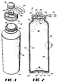
- Figs. 1-6 show the details of a PET syrup container 10 according to one embodiment of the present invention
- Fig. 7 shows the use of the container 10 to supply syrup 48 (see Fig. 2) to a post-mix beverage dispenser 12
- Figs. 8 and 9 show a container according to a preferred embodiment of this invention
- Fig. 10 shows another container of this invention.
- a syrup tube or line 14 connects the container 10 to the dispenser 12 with a syrup pump 15 in the line.
- the pump 15 is typically operated by gas such as by being connected to a CO 2 source 16 through a CO 2 line 18.
- the dispenser 12 is any well-known dispenser and includes an inlet water line 20 connected thereto and includes a plurality of beverage dispensing valves 22 for dispensing a selected beverage from a nozzle 24 into a cup 26 located on a drip tray 28.
- the syrup line 14 is attached to the container by a known quick-disconnect coupling 30 on the distal end of the line 14.
- the container 10 includes a wall 32, a container opening 34 (for filling and evacuation) surrounded by a neck 36, an air vent 38 extending partway through the wall, and a closure 50.
- the wall includes an outer PET layer 40, an inner PET layer 42, and a release agent therebetween such as a layer 44 of EVOH.
- the EVOH layer is known for use as an oxygen barrier and in such cases an adhesive layer is used on both sides of the EVOH layer.
- the release layer 44 can be EVOH but the EVOH does not have to have barrier properties, just release properties.
- no adhesive layer is needed, although it can be used on one side only of the EVOH layer, if desired.
- Fig. 4 shows the area around the air vent 38 before evacuation begins.
- Fig. 5 shows what happens when evacuation begins and the inner layer 42 begins to separate from the outer layer 40 and the EVOH layer 44 producing an air space 46 therebetween.
- Fig. 6 shows what happens after partial evacuation.
- the inner layer 42 simply separates from the outer and EVOH layers and surrounds the remaining syrup, similarly to what happens in the present bag-in-box system of a plastic bag in a paperboard box.
- a closure 50 is attached to the neck 36 of the container. Between the time of manufacture and filling, a dust cap (not shown) may be attached to cover the container opening, if desired.
- the closure includes a cap 52 screw threaded thereon and which is removed when the quick-disconnect coupling 30 is to be attached to the container.
- the closure 50 includes screw threads 54 for connecting to the container 10 and screw threads 56 for connecting to the syrup line coupling 30.
- the screw threads 54 on the closure and/or the screw threads on the neck 36 are preferably ratchet type so that the closure 50 cannot be removed.
- the screw threads 56 are the same as used now on bag-in-box bag valves for connecting to known syrup couplings.
- the coupling 30 includes a pin 58 to actuate (open) the valve (not shown) in the coupling 30 in the manner-known in the art as the coupling 30 is attached to the closure 50.
- the closure 50 includes a closure opening 60 for evacuating the syrup therefrom when the pump is energized.
- the opening 60 includes a plurality of small holes as shown in Fig. 2. The advantage of the opening 60 being a plurality of holes is that it makes unauthorized refilling difficult.
- the closure 50 also includes means for preventing the inner layer 42 from collapsing against and closing off the opening 60 prior to all of the syrup being evacuated.
- this means includes a plurality of ribs 62, although other means such as dip tubes, dip strips and perforated hollow cylinders can be used, as desired.
- the closure 50 also preferably includes a handle 64 preferably molded or formed as part of the closure.
- the handle can include a weakened area to act as a hinge 66 for the handle.
- the ribs 62 can have whatever dimensions are found to work best to achieve the above-stated purpose.
- the bottom of the container 10 includes the air vent 38, which is preferably about 10 mm (3/8 inch) in diameter.
- Various spacer means can be used to ensure free flow of air into the air vent such as a concave bottom wall 70 surrounded by an annular base 74 with a plurality, preferably four, small radial air slots 72 in the bottom surface of the annular base 74. While this is the preferred arrangement, alternatively the container bottom can be convex and a separate base cup with air openings can be added to the container to keep the air vent 38 from being closed off by contact with the floor.
- the wall (at least the elongated portion thereof between the neck and the base) can be provided or formed with strengthening ribs as shown in Fig. 3. Any known form of strengthening ribs can be used. Those shown are very gently curving, with the radial distance from crest to valley being about 3 to 6 mm (1/8 to 1/4 inch) and the vertical distance from crest to crest being about three to four times the radial distance or about 13 to 25 mm (1/2 to 1 inch). Vertically extending ribs would be preferred, having a distance of about 25 mm (one inch) from crest to crest and a depth of about 3 mm (1/8 inch).
- the container 10 is preferably cylindrical with a diameter of about 200 mm (8 inches) and a height of about 690 mm (27 inches) to hold 18.9 litres (five gallons) of syrup.
- the inner and outer walls are preferably of PET and the release layer is preferably EVOH.
- the outer layer is preferably about 0.51 to 0.64 mm (.02 to .025 inch) thick.
- the inner layer is preferably about 0.038 to 0.076 mm (.0015 to .0030 inch) thick.
- the EVOH layer is preferably about 0.025 mm (.001 inch) thick.
- the container opening 34 is preferably about 50 mm. in diameter.
- the wall 32 of the container is thicker at the neck 36 (about 3mm (1/8 inch)) similar to the thickness variation in present PET bottles.
- the air vent 38 extends through the outer and middle layers but not through the inner layer 42.
- This air vent hole can be produced in any desired manner, such as by drilling after manufacture or forming during manufacture (forming is preferred).
- the container wall includes a delaminatable portion where the EVOH layer is located and a non-delaminatable portion where there is no EVOH layer, such as at the neck.
- Figs. 8 and 9 show a container 100 according to a preferred embodiment of this invention.
- the container 100 is similar to the container 10 of Figs. 1-7 and can be used in the same way.
- the container 100 includes a wall 102, a container opening 104 surrounded by a neck 106 and three air vents 108, 110 and 112 extending partway through the wall.
- the wall 102 includes a thick, main central PET layer 114 and thin inner and outer PET layers 116 and 118, respectively, with thin inner and outer layers 120 and 122, respectively, of release agent (preferably EVOH) between the thin layers and the main layer.
- release agent preferably EVOH
- the container 100 preferably has vertical ribs for strength.
- the container 100 has two additional air vents 108 and 110 (preferably about 6 mm (1/4 inch) in diameter) and that there is an additional PET layer 118 on the outside of the main PET layer 114 with an additional layer 122 of EVOH therebetween as shown in Fig. 9.
- the inner and outer wall layers 116 and 118 preferably have a thickness of about 0.038 to 0.076 mm (.0015 to .0030) inch, the main layer 114 is preferably about 0.51 to 0.64 mm (.02 to .025 inch) thick.
- the EVOH is preferably about 0.025 mm (.001 inch) thick.
- the air vent 38 or 112 When the container 10 or 100 is placed horizontally in use, the air vent 38 or 112 is sufficient. However, when placed vertically, the weight of the syrup can keep the air vent 38 closed and the entire container 10 could collapse as the syrup is withdrawn.
- the purpose for the additional air vents 108 and 110 is to prevent such collapse and to ensure that the inner layer 116 collapses and releases from the remainder of the wall of the container.
- one air vent 108 is toward the top and one air vent 110 is toward the bottom of the container 100.
- the air vents 108 and 110 are preferably axially spaced-apart and approximately in-line circumferentially.
- the wall is all PET, with no EVOH, as shown in Fig. 8.
- the container 100 preferably has vertical (axially extending) ribs for strength, although it can also have circumferential ribs in addition to the vertical ribs.
- Fig. 10 shows a container 130 like container 100 except that it has only one side air vent 132 plus a bottom air vent 134.
- the air vents can be formed in any desired fashion, including drilling, and terminate at the inner PET layer 116, that is, they terminate directly at the inner layer or in or at the inner EVOH layer adjacent the inner PET layer.
- the air vents extend through the rest of the layers, including the other PET layer or layers and any other release layer(s).
- the air vents preferably extend through the EVOH layer adjacent the inner PET layer, although this is not essential.
- the containers are preferably manufactured by blow molding from laminated preforms using any well-known stretch and blow process from a coextruded preform, as described, for example, in U.S. Patents 4,032,341 and 4,609,516.
- the containers can be used in any position, but vertical is preferred. No container valve is required, unless the coupling is to be connected while the container is horizontal.
- the containers can be used with the same exact equipment presently used with the existing bag-in-box syrup container.
- the wall layers 40, 42, 114, 116 and 118 are preferably all made of PET and the closure of polyethylene for ease of recycling. While a particular handle has been shown, others can be used, such as one separate from the closure to connect to the bottle under the flange 136.
- the containers are preferably cylindrical although other shapes such as cubical (with rounded corners) or spherical can be used.
- the container can be made in any desired size, such as 3.8 litres (one gallon), 7.6 litres (two gallon), etc.
- the preferred application is for use with syrup in post-mix beverage dispensing; however, other liquids and other applications can be used.
- the container is preferably disposable, although it can be reused by blowing the inner layer back to its original position and shape, cleaning and refilling.
- Other plastics than PET and other release layers or agents than EVOH can be used.
- other plastic materials such as certain nylons, copolyesters, polypropylene (PP), PP/PET blends, polyacrylonitrile, polycarbonate and the like can be used.
- PP polypropylene
- PP/PET blends polyacrylonitrile, polycarbonate and the like
- the present invention provides a syrup container system for post-mix beverage dispensing using a disposable and recyclable plastic syrup container in lieu of a conventional bag-in-box type of container, and which can be used with the same identical equipment used with bag-in-box type containers, including the same syrup pump, sold-out device, and quick-disconnect coupling.
Abstract
Description
- The present invention relates to a blow molded plastic container of laminated construction for syrup or flavor concentrate suitable for use with a post-mix beverage dispenser. More specifically, the present invention relates to a disposable and recyclable container for supplying syrup or flavor concentrate, said container being connectable to a syrup pump which withdraws the syrup or flavor concentrate from the container by suction and feeds it to a post-mix dispenser.
- In post-mix beverage dispensers, such as those used in fast-food restaurants or the like, the syrup is presently supplied from either a reusable stainless steel, pressurized container with a 18.9 litre (five-gallon) capacity, or a disposable bag-in-box type of container. The stainless steel type of container is known as a "figal", an accepted abbreviation in the beverage dispensing art for a syrup container with a 18.9 litre (five-gallon) capacity fabricated primarily of stainless steel. "Figal" containers are generally described in U.S. -A- 3,186,577 to Tennison. Because the figal container must be strong enough to withstand the CO2 pressure used to pressurize the Figal to force the syrup to the dispenser, it is relatively expensive to manufacture, and it must be kept after use and then returned to the syrup supplier, where it is sanitized and reused.
- In contrast, bag-in-box packages for syrup are disposable, more convenient and less expensive. However, known bag-in-box type packages are not easily recyclable because of the many different materials used therein including the outer shrink wrap, the paperboard box, the two layer bag, the spout, the dipstrip, and the valve. Thus, an associated waste disposal problem results. A typical bag-in-box type package is disclosed in U.S. -A- 4,286,636.
- Bag-in-box packages of the general type disclosed in US-A- 4 286 636 are in wide use today in beverage dispensing systems which include gas-operated reciprocating pumps in the syrup line between the bag-in-box package and the dispenser. The syrup line is connected to the bag by a quick-disconnect coupling. An example of such a quick-disconnect coupling is also illustrated in US-A- 4 286 636.
- GB-A-1455453 discloses an aerosol can having an outer metal can and an inner wall. The package is filled less than full to leave room for a pressure fluid injected through a filler valve, which then closes to contain the pressure fluid. As the can is pressurised it does not have air vents in the outer metal can which are permanently open to atmosphere.
- Accordingly, a need exists in the art for a disposable, inexpensive syrup container for use with post-mix beverage dispensers, which is also recyclable.
- According to the present invention there is provided a liquid container as set out in claim 1.
- Thus a liquid container system according to one embodiment of the present invention comprises filling a PET container with syrup and connecting the syrup container to a post-mix beverage dispenser through a bag-in-box syrup pump. The syrup container includes a wall, a container opening, an air vent or a plurality of air vents, and a PET closure connected to the container opening. The wall preferably includes an outer and an inner PET layer and a release agent therebetween, such as a layer of EVOH. As syrup is withdrawn from the container, the inner PET layer separates from the outer PET layer and collapses around the remaining syrup, eliminating the need for venting the syrup chamber to atmosphere. When all of the syrup has been evacuated, a vacuum is drawn so that existing bag-in-box sold-out devices can be used. After use, the PET container is disposable and can be recycled.
- Some embodiments of the invention will now be described by way of example and with reference to the accompanying drawings wherein like reference numerals refer to like elements and wherein:
- Fig. 1 is a perspective view of a container according to the present invention;
- Fig. 2 is a cross-sectional view of a syrup container according to the present invention;
- Fig. 3 is an enlarged, partial view of a portion of the container of Fig. 2;
- Fig. 4 is an enlarged, partial cross-sectional view through the air vent area of the container of Fig. 1 as it appears after manufacture;
- Fig. 5 is a view identical to Fig. 2 but showing the separation occurring at the beginning of product evacuation from the container;
- Fig. 6 is a cross-sectional view of the container of Fig. 1 after partial evacuation of the syrup therefrom;
- Fig. 7 is a partly schematic, partly diagrammatic view of a syrup container system according to the present invention;
- Fig. 8 is a cross-sectional view through a container according to a preferred embodiment of this invention;
- Fig. 9 is an enlarged, partial cross-sectional view through a portion of the wall of the container of Fig. 8; and
- Fig. 10 is a view like Fig. 8 of another container of this invention.
- Figs. 1-6 show the details of a
PET syrup container 10 according to one embodiment of the present invention, Fig. 7 shows the use of thecontainer 10 to supply syrup 48 (see Fig. 2) to apost-mix beverage dispenser 12, Figs. 8 and 9 show a container according to a preferred embodiment of this invention and Fig. 10 shows another container of this invention. - Referring to Fig. 7, a syrup tube or
line 14 connects thecontainer 10 to thedispenser 12 with asyrup pump 15 in the line. Thepump 15 is typically operated by gas such as by being connected to a CO2 source 16 through a CO2 line 18. Thedispenser 12 is any well-known dispenser and includes aninlet water line 20 connected thereto and includes a plurality ofbeverage dispensing valves 22 for dispensing a selected beverage from anozzle 24 into acup 26 located on adrip tray 28. Thesyrup line 14 is attached to the container by a known quick-disconnect coupling 30 on the distal end of theline 14. - Referring to Figs. 1-6, the
container 10 includes awall 32, a container opening 34 (for filling and evacuation) surrounded by aneck 36, anair vent 38 extending partway through the wall, and aclosure 50. The wall includes anouter PET layer 40, aninner PET layer 42, and a release agent therebetween such as alayer 44 of EVOH. - The EVOH layer is known for use as an oxygen barrier and in such cases an adhesive layer is used on both sides of the EVOH layer. However, in the
container 10, therelease layer 44 can be EVOH but the EVOH does not have to have barrier properties, just release properties. In thecontainer 10, no adhesive layer is needed, although it can be used on one side only of the EVOH layer, if desired. In the preferred embodiment, there is no adhesive between the EVOH and the inner PET layer. - Fig. 4 shows the area around the
air vent 38 before evacuation begins. Fig. 5 shows what happens when evacuation begins and theinner layer 42 begins to separate from theouter layer 40 and theEVOH layer 44 producing anair space 46 therebetween. - Fig. 6 shows what happens after partial evacuation. The
inner layer 42 simply separates from the outer and EVOH layers and surrounds the remaining syrup, similarly to what happens in the present bag-in-box system of a plastic bag in a paperboard box. - Certain features of the present embodiment will now be described in detail.
- After the
container 10 is filled with syrup through the container opening 34, aclosure 50 is attached to theneck 36 of the container. Between the time of manufacture and filling, a dust cap (not shown) may be attached to cover the container opening, if desired. The closure includes acap 52 screw threaded thereon and which is removed when the quick-disconnect coupling 30 is to be attached to the container. - The
closure 50 includesscrew threads 54 for connecting to thecontainer 10 andscrew threads 56 for connecting to thesyrup line coupling 30. Thescrew threads 54 on the closure and/or the screw threads on theneck 36 are preferably ratchet type so that theclosure 50 cannot be removed. Thescrew threads 56 are the same as used now on bag-in-box bag valves for connecting to known syrup couplings. - The
coupling 30 includes apin 58 to actuate (open) the valve (not shown) in thecoupling 30 in the manner-known in the art as thecoupling 30 is attached to theclosure 50. Theclosure 50 includes a closure opening 60 for evacuating the syrup therefrom when the pump is energized. In the preferred embodiment the opening 60 includes a plurality of small holes as shown in Fig. 2. The advantage of the opening 60 being a plurality of holes is that it makes unauthorized refilling difficult. Theclosure 50 also includes means for preventing theinner layer 42 from collapsing against and closing off the opening 60 prior to all of the syrup being evacuated. In a preferred embodiment this means includes a plurality ofribs 62, although other means such as dip tubes, dip strips and perforated hollow cylinders can be used, as desired. Theclosure 50 also preferably includes ahandle 64 preferably molded or formed as part of the closure. The handle can include a weakened area to act as ahinge 66 for the handle. Theribs 62 can have whatever dimensions are found to work best to achieve the above-stated purpose. - The bottom of the
container 10 includes theair vent 38, which is preferably about 10 mm (3/8 inch) in diameter. Various spacer means can be used to ensure free flow of air into the air vent such as aconcave bottom wall 70 surrounded by anannular base 74 with a plurality, preferably four, smallradial air slots 72 in the bottom surface of theannular base 74. While this is the preferred arrangement, alternatively the container bottom can be convex and a separate base cup with air openings can be added to the container to keep theair vent 38 from being closed off by contact with the floor. - To provide additional strength to the
container 10, the wall (at least the elongated portion thereof between the neck and the base) can be provided or formed with strengthening ribs as shown in Fig. 3. Any known form of strengthening ribs can be used. Those shown are very gently curving, with the radial distance from crest to valley being about 3 to 6 mm (1/8 to 1/4 inch) and the vertical distance from crest to crest being about three to four times the radial distance or about 13 to 25 mm (1/2 to 1 inch). Vertically extending ribs would be preferred, having a distance of about 25 mm (one inch) from crest to crest and a depth of about 3 mm (1/8 inch). - The
container 10 is preferably cylindrical with a diameter of about 200 mm (8 inches) and a height of about 690 mm (27 inches) to hold 18.9 litres (five gallons) of syrup. The inner and outer walls are preferably of PET and the release layer is preferably EVOH. The outer layer is preferably about 0.51 to 0.64 mm (.02 to .025 inch) thick. The inner layer is preferably about 0.038 to 0.076 mm (.0015 to .0030 inch) thick. The EVOH layer is preferably about 0.025 mm (.001 inch) thick. Thecontainer opening 34 is preferably about 50 mm. in diameter. Thewall 32 of the container is thicker at the neck 36 (about 3mm (1/8 inch)) similar to the thickness variation in present PET bottles. - The
air vent 38 extends through the outer and middle layers but not through theinner layer 42. This air vent hole can be produced in any desired manner, such as by drilling after manufacture or forming during manufacture (forming is preferred). - The three layers are laminated together but the bonding between the
inner layer 42 and theEVOH layer 44 is weak such that as syrup is evacuated from thecontainer 10, the inner layer will separate from the EVOH layer as shown in Figs. 5 and 6. The EVOH layer could separate from the outer layer and stay with the inner layer, but that is not the preferred embodiment. For other release agents, the release agent may not even be a separate layer of material. Preferably, theEVOH layer 44 stops short of the top edge of theneck 36 and the inner and outer layers are bonded together in this area to prevent separation or delamination. The EvoH layer can stop as low as about one-half way up the height of the container, however, preferably it extends all the way up to just short of the neck. Thus, the container wall includes a delaminatable portion where the EVOH layer is located and a non-delaminatable portion where there is no EVOH layer, such as at the neck. - Figs. 8 and 9 show a
container 100 according to a preferred embodiment of this invention. Thecontainer 100 is similar to thecontainer 10 of Figs. 1-7 and can be used in the same way. - The
container 100 includes awall 102, acontainer opening 104 surrounded by aneck 106 and threeair vents wall 102 includes a thick, maincentral PET layer 114 and thin inner and outer PET layers 116 and 118, respectively, with thin inner andouter layers container 100 preferably has vertical ribs for strength. - The differences between the
container 100 and thecontainer 10 are that thecontainer 100 has twoadditional air vents 108 and 110 (preferably about 6 mm (1/4 inch) in diameter) and that there is anadditional PET layer 118 on the outside of themain PET layer 114 with anadditional layer 122 of EVOH therebetween as shown in Fig. 9. The inner and outer wall layers 116 and 118 preferably have a thickness of about 0.038 to 0.076 mm (.0015 to .0030) inch, themain layer 114 is preferably about 0.51 to 0.64 mm (.02 to .025 inch) thick. The EVOH is preferably about 0.025 mm (.001 inch) thick. - When the
container air vent air vent 38 closed and theentire container 10 could collapse as the syrup is withdrawn. The purpose for theadditional air vents inner layer 116 collapses and releases from the remainder of the wall of the container. Preferably, oneair vent 108 is toward the top and oneair vent 110 is toward the bottom of thecontainer 100. The air vents 108 and 110 are preferably axially spaced-apart and approximately in-line circumferentially. - In the portion of the container wall surrounding the
opening 104, the wall is all PET, with no EVOH, as shown in Fig. 8. - The
container 100 preferably has vertical (axially extending) ribs for strength, although it can also have circumferential ribs in addition to the vertical ribs. - Fig. 10 shows a
container 130 likecontainer 100 except that it has only oneside air vent 132 plus abottom air vent 134. - The air vents can be formed in any desired fashion, including drilling, and terminate at the
inner PET layer 116, that is, they terminate directly at the inner layer or in or at the inner EVOH layer adjacent the inner PET layer. The air vents extend through the rest of the layers, including the other PET layer or layers and any other release layer(s). The air vents preferably extend through the EVOH layer adjacent the inner PET layer, although this is not essential. - The containers are preferably manufactured by blow molding from laminated preforms using any well-known stretch and blow process from a coextruded preform, as described, for example, in U.S. Patents 4,032,341 and 4,609,516.
- The containers can be used in any position, but vertical is preferred. No container valve is required, unless the coupling is to be connected while the container is horizontal. The containers can be used with the same exact equipment presently used with the existing bag-in-box syrup container.
- While the preferred embodiment of this invention has been described above in detail, it is to be understood that variations and modifications can be made therein without departing from the scope of the present invention. For example, while various numbers of PET layers have been shown, additional layers can be used, if desired. While various air vents have been shown, others can be used and in different locations, if desired. The wall layers 40, 42, 114, 116 and 118 are preferably all made of PET and the closure of polyethylene for ease of recycling. While a particular handle has been shown, others can be used, such as one separate from the closure to connect to the bottle under the flange 136. The containers are preferably cylindrical although other shapes such as cubical (with rounded corners) or spherical can be used. While the preferred container size is 18.9 litres (five gallons), the container can be made in any desired size, such as 3.8 litres (one gallon), 7.6 litres (two gallon), etc. The preferred application is for use with syrup in post-mix beverage dispensing; however, other liquids and other applications can be used. The container is preferably disposable, although it can be reused by blowing the inner layer back to its original position and shape, cleaning and refilling. Other plastics than PET and other release layers or agents than EVOH can be used. For example, depending on the use of the container, other plastic materials such as certain nylons, copolyesters, polypropylene (PP), PP/PET blends, polyacrylonitrile, polycarbonate and the like can be used. When using a plurality of air vents, it is preferred to have one in the bottom wall of the container, although this is not essential. When using a plurality of air vents, it is not necessary to have the spacer means.
- It will thus be seen that the present invention, at least in its preferred forms, provides a syrup container system for post-mix beverage dispensing using a disposable and recyclable plastic syrup container in lieu of a conventional bag-in-box type of container, and which can be used with the same identical equipment used with bag-in-box type containers, including the same syrup pump, sold-out device, and quick-disconnect coupling.
Claims (14)
- A liquid container comprising:(a) a wall (32), a container opening (34) for filling and evacuating said container surrounded by a container neck (36), and an air vent (38) extending partway through said wall;(b) said wall including an outer PET layer (40) and an inner PET layer (42), said wall including a delaminatable portion and a non-delaminatable portion, and a release agent (44) located between said layers over said delaminatable portion of said container wall such that said inner layer can separate from said outer layer when liquid is evacuated from said container and air flows in through said air vent;(c) said air vent extending through said outer layer and terminating at said inner layer, and said air vent being permanently open to atmosphere, such that air can flow through said air vent and in between said inner and outer PET layers as liquid is withdrawn from said container;(d) said inner and outer PET layers being bonded directly together in said non-delaminatable portion of said wall and said non-delaminatable portion including said container neck;(e) said container including a closure (50) connected to said container neck and sealing said container opening closed;(f) means for non-removably connecting said closure to said container; and(g) said closure including a closure opening (60) therethrough, a removable cap (52) for closing said closure opening prior to connecting a coupling (30) thereto, means (62) for preventing said inner layer from sealing off said closure opening prior to complete liquid evacuation, and means (58) for engaging and opening a valve in a quick-disconnect liquid coupling (30) when connected to said closure.
- A container as claimed in claim 1, including spacer means (70) for maintaining said air vent (38) open and out of contact with an external surface.
- A container as claimed in claim 2, wherein said container wall (32) includes a concave bottom wall (70) surrounded by an annular base (74), said air vent (38) being centrally located in said concave bottom wall, and including a plurality of air slots (72) in said annular base to allow unrestricted air flow to said air vent.
- A container as claimed in any preceding claim, wherein said closure opening (60) includes a plurality of small holes.
- A container as claimed in any preceding claim, including an additional PET layer (118) on the outside of said outer PET layer (114) and an additional layer of release agent (122) located between said outer PET layer and said additional PET layer.
- A container as claimed in any preceding claim including a plurality of said air vents.
- A container as claimed in claim 6, wherein said container includes a bottom wall and a sidewall and wherein one said air vent (134) is in said bottom wall and including at least one additional side air vent (132) in said sidewall.
- A container as claimed in claim 6 or 7, including a pair of axially spaced-apart air vents (108,110) in said sidewall.
- A container as claimed in any of claims 6 to 8, wherein said bottom wall air vent (134;112) has a diameter of about 10 mm (3/8 inch) and said at least one sidewall air vent (132;108,110) has a diameter of about 6 mm (1/4 inch).
- A container as claimed in any of claims 6 to 9, wherein said at least one side air vent (132) consists of a single side air vent.
- A container as claimed in claim 10, wherein said single side air vent (132) is centrally located in said sidewall between the top and bottom of said container.
- A container as claimed in any preceding claim, wherein the or each said air vent (38;134,132;112,108, 110) has a diameter of about 10 mm (3/8 inch).
- A container as claimed in any preceding claim, wherein said release agent comprises a layer of EVOH.
- In combination, a post-mix beverage dispenser (12) and a container (10) as claimed in any preceding claim, said container being connected to said dispenser via a syrup line having a pump (15) therein by means of a said coupling (30).
Applications Claiming Priority (5)
| Application Number | Priority Date | Filing Date | Title |
|---|---|---|---|
| US62881990A | 1990-12-17 | 1990-12-17 | |
| US628819 | 1990-12-17 | ||
| US07/803,241 US5242085A (en) | 1990-12-17 | 1991-12-05 | Liquid container system |
| US803241 | 1991-12-05 | ||
| PCT/US1991/009171 WO1992011187A1 (en) | 1990-12-17 | 1991-12-17 | Liquid container system |
Publications (2)
| Publication Number | Publication Date |
|---|---|
| EP0562019A1 EP0562019A1 (en) | 1993-09-29 |
| EP0562019B1 true EP0562019B1 (en) | 1997-03-12 |
Family
ID=27090797
Family Applications (1)
| Application Number | Title | Priority Date | Filing Date |
|---|---|---|---|
| EP92903102A Expired - Lifetime EP0562019B1 (en) | 1990-12-17 | 1991-12-17 | Liquid container |
Country Status (10)
| Country | Link |
|---|---|
| US (4) | US5242085A (en) |
| EP (1) | EP0562019B1 (en) |
| AT (1) | ATE149953T1 (en) |
| AU (1) | AU646126B2 (en) |
| BR (1) | BR9107234A (en) |
| CA (1) | CA2099616A1 (en) |
| DE (1) | DE69125177T2 (en) |
| FI (1) | FI932817A (en) |
| MX (1) | MX9102605A (en) |
| WO (1) | WO1992011187A1 (en) |
Families Citing this family (88)
| Publication number | Priority date | Publication date | Assignee | Title |
|---|---|---|---|---|
| US5242085A (en) * | 1990-12-17 | 1993-09-07 | The Coca-Cola Company | Liquid container system |
| US5344045A (en) * | 1990-12-17 | 1994-09-06 | The Coca-Cola Company | Liquid container system |
| US5301838A (en) * | 1991-01-23 | 1994-04-12 | Continental Pet Technologies, Inc. | Multilayer bottle with separable inner layer and method for forming same |
| DE69227822T2 (en) * | 1991-08-05 | 1999-07-29 | Yoshino Kogyosho Co Ltd | LAMINATED BOTTLE AND METHOD FOR THEIR PRODUCTION |
| DE4139555A1 (en) * | 1991-09-18 | 1993-03-25 | Gaplast Gmbh | CONTAINER |
| DE4209436A1 (en) * | 1992-02-05 | 1993-08-12 | Henkel Kgaa | THIN-WALLED PLASTIC BOTTLE WITH A STRUCTURED SURFACE |
| EP1026086B1 (en) * | 1992-05-11 | 2003-10-08 | YOSHINO KOGYOSHO Co., Ltd. | Pump unit for a laminated bottle |
| JP2999071B2 (en) * | 1992-08-12 | 2000-01-17 | 麒麟麦酒株式会社 | Bag body and bag-in-box for bag-in-box |
| EP0599301B1 (en) * | 1992-11-24 | 1997-03-12 | Coster Tecnologie Speciali S.P.A. | Device for metered dispensing of flowable product from a container |
| AU6157794A (en) * | 1993-02-23 | 1994-09-14 | Karl Magnus Dahlberg | Reusable container with an inner liner, and a method for making such a container |
| JP3595571B2 (en) * | 1993-05-07 | 2004-12-02 | 日精エー・エス・ビー機械株式会社 | Double wall bottle and method and apparatus for molding the same |
| US6749604B1 (en) * | 1993-05-10 | 2004-06-15 | Arthrocare Corporation | Electrosurgical instrument with axially-spaced electrodes |
| US5516007A (en) * | 1994-12-12 | 1996-05-14 | Larson; Donna M. | Dispenser |
| US5538160A (en) * | 1994-12-16 | 1996-07-23 | The Coca-Cola Company | Postmix beverage dispenser with water boost |
| EP1266698B1 (en) * | 1995-03-10 | 2006-05-24 | Yoshino Kogyosho Co., Ltd. | Separable laminated container |
| AU715849B2 (en) * | 1995-04-17 | 2000-02-10 | Canon Kabushiki Kaisha | Liquid container |
| AU741550B2 (en) * | 1995-04-17 | 2001-12-06 | Canon Kabushiki Kaisha | Ink container |
| JP3251845B2 (en) | 1995-04-17 | 2002-01-28 | キヤノン株式会社 | Liquid container for applying negative pressure, method for manufacturing the container, ink jet cartridge integrating the container with an ink jet recording head, and ink jet recording apparatus |
| JP3098412B2 (en) | 1995-11-27 | 2000-10-16 | 株式会社青木固研究所 | Bottle with hanging tool by stretch blow molding |
| AU6419496A (en) * | 1996-04-02 | 1997-10-22 | Luis Garcia Garcia | Improved package for fluids |
| DE19615422A1 (en) | 1996-04-19 | 1997-11-20 | Boehringer Ingelheim Kg | Two-chamber cartridge for propellant-free MDIs |
| JP3181235B2 (en) | 1997-01-31 | 2001-07-03 | 株式会社青木固研究所 | Biaxially stretched bottle with a hand |
| CA2230768C (en) * | 1997-02-28 | 2007-02-13 | John W. Safian | Multilayer container package |
| US6685691B1 (en) | 1998-02-27 | 2004-02-03 | Boehringer Ingelheim Gmbh | Container for a medicinal liquid |
| US7963955B2 (en) * | 1998-02-27 | 2011-06-21 | Boehringer Ingelheim International Gmbh | Container for a medicinal liquid |
| US6179142B1 (en) | 1998-04-13 | 2001-01-30 | The Coca-Cola Company | Wire-frame bottle and method of manufacturing same |
| DE19831540C5 (en) | 1998-07-14 | 2005-07-07 | Groß, Heinz, Dr.-Ing. | Partial change of the flow channel cross section of a closed flow channel cross section |
| DE19851404A1 (en) * | 1998-11-07 | 2000-05-11 | Boehringer Ingelheim Int | Pressure compensation device for a double tank |
| US6269837B1 (en) | 1998-11-09 | 2001-08-07 | The Procter & Gamble Company | Rechargeable dispensing system |
| DE19940713A1 (en) | 1999-02-23 | 2001-03-01 | Boehringer Ingelheim Int | Diffusion resistant cartridge for storing and dosing liquids, especially for producing drug-containing inhalable aerosols, has three-shell structure with collapsible bag, container and rigid housing |
| US6145513A (en) * | 1999-02-26 | 2000-11-14 | New Basics, Inc. | Hair dye applicator |
| US20040076782A1 (en) * | 1999-04-07 | 2004-04-22 | Safian John W. | Multilayer container |
| US6670007B1 (en) | 1999-04-07 | 2003-12-30 | Owens-Brockway Plastic Products Inc. | Multilayer container |
| US20070292646A1 (en) * | 1999-04-07 | 2007-12-20 | Graham Packaging Company L.P. | Multilayer container |
| US6422455B1 (en) | 2000-04-05 | 2002-07-23 | Sonoco Development, Inc. | Composite container for vacuum packaging food products such as dough and associated methods |
| GB0023394D0 (en) * | 2000-09-23 | 2000-11-08 | Imi Cornelius Uk Ltd | Liquid storage |
| JP3938300B2 (en) * | 2001-11-30 | 2007-06-27 | 株式会社吉野工業所 | Dispensing container |
| JP2003205973A (en) * | 2002-01-16 | 2003-07-22 | Canon Inc | Container for housing liquid and manufacturing method of same container |
| US6719173B2 (en) * | 2002-03-25 | 2004-04-13 | Owens-Brockway Plastic Products Inc. | Multilayer container package for dispensing a liquid product |
| AU2003281772A1 (en) * | 2002-07-25 | 2004-02-16 | Jae-Kun Lee | Dye container and hair dyeing device using the same |
| AU2003280165B2 (en) * | 2002-11-29 | 2009-07-16 | Interbrew S.A. | Beer dispensing system with gas pressure reservoir |
| AU2003301033A1 (en) * | 2002-12-17 | 2004-07-22 | New Basics, Inc. | Highlighting hair fluid applicator |
| AU2003301034A1 (en) * | 2002-12-17 | 2004-07-22 | New Basics, Inc. | Touch up/moustache hair fluid applicator |
| US20040149674A1 (en) * | 2003-01-30 | 2004-08-05 | Denis Corr | Quiet pill bottle |
| US7284579B2 (en) | 2003-03-28 | 2007-10-23 | Hyclone Laboratories, Inc. | Fluid dispensing bins and related methods |
| US6945429B2 (en) | 2003-06-10 | 2005-09-20 | Illinois Tool Works Inc. | Disposable paint cup attachment system for gravity-feed paint sprayer |
| FR2866010B1 (en) * | 2004-02-05 | 2007-04-27 | Tournaire Sa | CONTAINER WITH DEFORMABLE MULTILAYER INTERNAL POCKET AND METHOD OF OBTAINING THE SAME |
| DE102005000056A1 (en) * | 2005-05-10 | 2006-11-16 | Hilti Ag | cartridge |
| DE102005029746B4 (en) * | 2005-06-24 | 2017-10-26 | Boehringer Ingelheim International Gmbh | atomizer |
| US9944453B2 (en) * | 2007-04-19 | 2018-04-17 | Anheuser-Busch Inbev S.A. | Integrally blow-moulded bag-in-container having an inner layer and the outer layer made of the same material and preform for making it |
| US20080258356A1 (en) | 2007-04-19 | 2008-10-23 | Inbev S.A. | Integrally blow-moulded bag-in-container comprising an inner layer and an outer layer comprising energy absorbing additives, and preform for making it |
| US20080257883A1 (en) | 2007-04-19 | 2008-10-23 | Inbev S.A. | Integrally blow-moulded bag-in-container having an inner layer and the outer layer made of the same material and preform for making it |
| US9475611B2 (en) | 2007-04-19 | 2016-10-25 | Anheuser-Busch Inbev S.A. | Integrally blow-moulded bag-in-container having interface vents opening to the atmosphere at location adjacent to bag's mouth, preform for making it; and processes for producing the preform and bag-in-container |
| FI7694U1 (en) * | 2007-05-30 | 2007-11-30 | Matti Koskinen | Lure |
| NL1034895C2 (en) * | 2008-01-08 | 2009-07-13 | Dispensing Technologies Bv | Composite container and method for manufacturing thereof. |
| US8087532B2 (en) * | 2008-01-18 | 2012-01-03 | Brown Newman, L.L.C. | Waste container |
| US7740212B2 (en) * | 2008-04-17 | 2010-06-22 | ConeCraft, Inc, | Apparatus to retain and position tubing of media bags |
| US20090285949A1 (en) * | 2008-05-15 | 2009-11-19 | Wendell Brown | Expandable Food Container |
| EP2165968A1 (en) | 2008-09-19 | 2010-03-24 | InBev S.A. | Bag-in-container with prepressurized space between inner bag and outer container |
| NL2003132C2 (en) | 2009-07-03 | 2011-01-04 | Heineken Supply Chain Bv | Container, preform assembly and method and apparatus for forming containers. |
| EP2336078A1 (en) | 2009-12-18 | 2011-06-22 | Anheuser-Busch InBev S.A. | Pressurized gas driven liquid dispensing device comprising a piercing unit |
| EP2339421A1 (en) | 2009-12-18 | 2011-06-29 | Anheuser-Busch InBev S.A. | Pressure regulating valve for pressure driven beverage dispensing apparatuses |
| EP2336077A1 (en) | 2009-12-18 | 2011-06-22 | Anheuser-Busch InBev S.A. | Beverage dispensing apparatus comprising an integrated pressure reducing channel |
| US9046403B2 (en) * | 2010-02-01 | 2015-06-02 | Mallinckrodt Llc | Systems and methods for managing use of a medicament |
| EP2405164A1 (en) | 2010-07-08 | 2012-01-11 | Anheuser-Bush Inbev NV | Resilient closure for pressure driven dispensing container |
| TWI432363B (en) * | 2010-12-03 | 2014-04-01 | Ind Tech Res Inst | Anti-forgery bottled structure |
| US20120175366A1 (en) * | 2011-01-10 | 2012-07-12 | GM Global Technology Operations LLC | Vent hole alignment of temperature-pressure relief devices on pressure vessels |
| JP5979467B2 (en) * | 2011-08-31 | 2016-08-24 | 株式会社吉野工業所 | Laminated blow molded container and method for forming air inlet |
| US9376655B2 (en) | 2011-09-29 | 2016-06-28 | Life Technologies Corporation | Filter systems for separating microcarriers from cell culture solutions |
| NL2009235C2 (en) | 2012-07-26 | 2014-01-28 | Heineken Supply Chain Bv | Container and set of preforms for forming a container. |
| JP6112385B2 (en) * | 2012-08-31 | 2017-04-12 | 株式会社吉野工業所 | Blow molded container and manufacturing method thereof |
| CN102878425B (en) * | 2012-10-23 | 2014-01-22 | 张家港富瑞特种装备股份有限公司 | Device for avoiding liquid layering in liquefied natural gas storage tank |
| KR102402208B1 (en) * | 2013-11-27 | 2022-05-25 | 교라꾸 가부시끼가이샤 | Delamination Container |
| EP3075671B1 (en) * | 2013-11-27 | 2018-05-23 | Kyoraku Co., Ltd. | Delamination container and method of manufacturing it |
| EP3176100B1 (en) * | 2013-11-27 | 2018-06-20 | Kyoraku CO., LTD | Delamination container |
| US9850059B2 (en) * | 2014-03-20 | 2017-12-26 | Gojo Industries, Inc | Closed system for venting a dispenser reservoir |
| WO2016078763A1 (en) | 2014-11-20 | 2016-05-26 | Boehringer Ingehlheim Vetmedica Gmbh | Container for an inhaler |
| ES2732942T3 (en) | 2015-01-23 | 2019-11-26 | Kyoraku Co Ltd | Delaminable container |
| AR101299A1 (en) * | 2015-07-24 | 2016-12-07 | Valvulas Prec De Argentina S A C I | PRECINTO WITH UNLOCKABLE SAFETY WORK, APPLICABLE TO LIQUID DISPENSING HEADS |
| CN106809461A (en) * | 2015-12-01 | 2017-06-09 | 威玛精密化学科技股份有限公司 | Double container and its preparation method |
| USD799967S1 (en) * | 2016-01-15 | 2017-10-17 | Industries Lassonde Inc. | Plastic bottle |
| JP6912697B2 (en) * | 2016-10-14 | 2021-08-04 | キョーラク株式会社 | Laminate peeling container |
| EP3372372B1 (en) * | 2017-03-09 | 2019-09-11 | Aptar Radolfzell GmbH | Method for producing a container system and a liquid dispenser and container system with same and resulting liquid dispenser |
| EP3597562B1 (en) * | 2017-03-15 | 2021-10-13 | Kyoraku Co., Ltd. | Delamination container |
| US10759584B2 (en) | 2018-03-02 | 2020-09-01 | Life Technologies Corporation | System for port and tube holder assembly attachment device and methods of use |
| WO2019173718A1 (en) * | 2018-03-09 | 2019-09-12 | Dispenser Packaging, LLC | Liquid dispense system |
| US11891224B2 (en) * | 2019-06-12 | 2024-02-06 | Real Value LLC | Vessel lid and methods of making and using same |
| USD962007S1 (en) * | 2020-04-10 | 2022-08-30 | The International Company for Designs and Innovative Products | Syrup dispenser |
Family Cites Families (53)
| Publication number | Priority date | Publication date | Assignee | Title |
|---|---|---|---|---|
| US2732977A (en) * | 1956-01-31 | charpiat | ||
| BE570451A (en) * | ||||
| US2715980A (en) * | 1950-10-09 | 1955-08-23 | Leo M Harvey | Liquid handling dispenser |
| US3040933A (en) * | 1959-01-05 | 1962-06-26 | Edgar A Poe Jr | Pressure can having a flexible material holding bag therein |
| US3178062A (en) * | 1960-04-26 | 1965-04-13 | Welty Frank | Dispensing apparatus for pre-mixed beverages |
| US3161327A (en) * | 1962-02-15 | 1964-12-15 | Wilhelm Schmidding | Siphon dispenser |
| GB1032825A (en) * | 1962-03-20 | 1966-06-15 | John Sidney Gooch | Beverage storage and dispensing apparatus |
| US3118572A (en) * | 1962-09-04 | 1964-01-21 | Koppers Co Inc | Squeeze bottle |
| US3239102A (en) * | 1964-04-30 | 1966-03-08 | Pacific Sales Inc | Beverage dispenser |
| GB1171612A (en) * | 1964-10-10 | 1969-11-26 | Porter Lancastrian Ltd | Improvements relating to the Storage and Distribution of Carbonated Beverages |
| US3409714A (en) * | 1966-08-09 | 1968-11-05 | Goodrich Co B F | Fuel tank |
| US3945539A (en) * | 1966-08-16 | 1976-03-23 | Thiokol Corporation | Method and apparatus for expelling fluids |
| US3592360A (en) * | 1967-06-28 | 1971-07-13 | Arde Inc | Cylindrical fluid storage and expulsion tank |
| US3484011A (en) * | 1968-04-16 | 1969-12-16 | William Greenhalgh | Disposable container liner and advertising means |
| US3727780A (en) * | 1971-01-04 | 1973-04-17 | Bucciconi Eng Co | Scissors-type hoist mechanism |
| US3727783A (en) * | 1971-06-15 | 1973-04-17 | Du Pont | Noneverting bottom for thermoplastic bottles |
| US4350272A (en) * | 1971-09-15 | 1982-09-21 | Petterson Tor H | Product isolated aerosol container and method of manufacture |
| GB1421176A (en) * | 1971-12-25 | 1976-01-14 | Yoshino Kogyosho Co Ltd | Collapsible tube |
| US3940001A (en) * | 1972-10-06 | 1976-02-24 | Ethyl Corporation | Recyclable plastic containers |
| US4008831A (en) * | 1972-11-20 | 1977-02-22 | Jacques Vidilles | Safety reservoir for hydrocarbons and dangerous liquids |
| US3765574A (en) * | 1973-02-16 | 1973-10-16 | I Urquiza | Container for liquids |
| US3876119A (en) * | 1973-02-26 | 1975-04-08 | Denham Lee Roy | Inverting liner pressurized tank |
| US4008830A (en) * | 1973-08-10 | 1977-02-22 | Philip Meshberg | Liquid dispenser using a non vented pump and a collapsible plastic bag |
| GB1455453A (en) * | 1973-11-13 | 1976-11-10 | Petterson T H | Barrier package and method of manufacture |
| US4286636A (en) * | 1979-07-19 | 1981-09-01 | The Coca-Cola Company | Dip tube and valve with quick-disconnect coupling for a collapsible container |
| US4350227A (en) * | 1980-08-25 | 1982-09-21 | Bohn & Dawson | Wheelchair brake assembly |
| US4484697A (en) * | 1980-08-27 | 1984-11-27 | Shasta Beverages, Inc. | Method and apparatus for dispensing liquid |
| JPS58183243A (en) * | 1982-04-22 | 1983-10-26 | 株式会社吉野工業所 | Biaxial stretched blow molded bottle body made of synthetic resin |
| US4463875A (en) * | 1982-06-14 | 1984-08-07 | Robert W. Mann | Method and apparatus for preparing and applying a two-component cement |
| US4482588A (en) * | 1983-05-19 | 1984-11-13 | Eastman Kodak Company | Bonding compositions and shaped articles utilizing the bonding compositions |
| US4585146A (en) * | 1983-06-16 | 1986-04-29 | The Coca-Cola Company | Open top tank with flow rate control device therein |
| JPS6071207A (en) * | 1983-09-29 | 1985-04-23 | Toyo Seikan Kaisha Ltd | Multilayer preform for elongation blow molding and its manufacture |
| US4723688A (en) * | 1983-11-03 | 1988-02-09 | Munoz Edward A | Beverage container and dispenser |
| US4550043A (en) * | 1984-02-17 | 1985-10-29 | Continental Plastic Containers, Inc. | Preform with internal barrier and internal layer of high thermal stability and products made from the same |
| US4609516A (en) * | 1984-02-17 | 1986-09-02 | Continental Pet Technologies, Inc. | Method of forming laminated preforms |
| DE3442092A1 (en) * | 1984-11-17 | 1986-05-28 | Kautex Werke Reinold Hagen AG, 5300 Bonn | METHOD FOR PRODUCING A PACKAGING PROVIDED WITH A LOCKABLE OPENING AND PACKAGING PRODUCED BY THIS METHOD |
| DE3676803D1 (en) * | 1985-08-19 | 1991-02-14 | Splicerite Ltd | LIQUID CONTAINER. |
| US4696840A (en) * | 1985-12-13 | 1987-09-29 | The Procter & Gamble Company | Blown bag-in-box composite container and method and apparatus for making the same |
| US4708266A (en) * | 1986-03-21 | 1987-11-24 | The Coca-Cola Company | Concentrate dispensing system for a post-mix beverage dispenser |
| DE3618634A1 (en) * | 1986-06-03 | 1987-12-10 | Jean Pierre Denis | DISPENSER FOR BEVERAGES |
| AU7588587A (en) * | 1986-07-16 | 1988-02-10 | Richard Friedrich | Container with at least one chamber formed by a tubular body, tubular body, process and device for producing the same |
| US4796788A (en) * | 1987-08-26 | 1989-01-10 | Liqui-Box Corporation | Bag-in-box packaging and dispensing of substances which will not readily flow by gravity |
| US4881666A (en) * | 1988-01-19 | 1989-11-21 | Robert Tullman | Variable volume container |
| US4892230A (en) * | 1988-02-08 | 1990-01-09 | Lynn Jr Arthur E | Carbonated beverage bottle |
| US4913316A (en) * | 1988-07-27 | 1990-04-03 | The Coca - Cola Company | Binary syrup system bag and valve |
| US4972969A (en) * | 1988-09-19 | 1990-11-27 | Minnesota Mining And Manufacturing Company | Assembly for storing mixing and dispensing preparations such as dental materials |
| US4979631A (en) * | 1988-11-14 | 1990-12-25 | Continental Pet Technologies, Inc. | Vented recyclable multilayer barrier container |
| US4980100A (en) * | 1988-11-14 | 1990-12-25 | Continental Pet Technologies, Inc. | Vented recyclable multilayer barrier container, an apparatus for and method of making same |
| US4949871A (en) * | 1989-02-09 | 1990-08-21 | Aerosol Systems, Inc. | Barrier pack product dispensing cans |
| US4921135A (en) * | 1989-03-03 | 1990-05-01 | Lawrence Pleet | Pressurized beverage container dispensing system |
| US5037002A (en) * | 1990-07-11 | 1991-08-06 | Liqui-Box/B-Bar-B Corporation | Integral self-supporting and recyclable liquid container |
| US5242085A (en) * | 1990-12-17 | 1993-09-07 | The Coca-Cola Company | Liquid container system |
| US5301838A (en) * | 1991-01-23 | 1994-04-12 | Continental Pet Technologies, Inc. | Multilayer bottle with separable inner layer and method for forming same |
-
1991
- 1991-12-05 US US07/803,241 patent/US5242085A/en not_active Expired - Fee Related
- 1991-12-17 AU AU91625/91A patent/AU646126B2/en not_active Ceased
- 1991-12-17 MX MX9102605A patent/MX9102605A/en unknown
- 1991-12-17 EP EP92903102A patent/EP0562019B1/en not_active Expired - Lifetime
- 1991-12-17 WO PCT/US1991/009171 patent/WO1992011187A1/en active IP Right Grant
- 1991-12-17 CA CA002099616A patent/CA2099616A1/en not_active Abandoned
- 1991-12-17 AT AT92903102T patent/ATE149953T1/en not_active IP Right Cessation
- 1991-12-17 BR BR919107234A patent/BR9107234A/en not_active Application Discontinuation
- 1991-12-17 DE DE69125177T patent/DE69125177T2/en not_active Expired - Fee Related
-
1993
- 1993-01-14 US US08/004,736 patent/US5242086A/en not_active Expired - Fee Related
- 1993-06-17 FI FI932817A patent/FI932817A/en not_active Application Discontinuation
- 1993-09-02 US US08/115,390 patent/US5385269A/en not_active Expired - Lifetime
- 1993-09-02 US US08/116,154 patent/US5383576A/en not_active Expired - Lifetime
Also Published As
| Publication number | Publication date |
|---|---|
| US5242086A (en) | 1993-09-07 |
| DE69125177T2 (en) | 1997-09-18 |
| US5242085A (en) | 1993-09-07 |
| ATE149953T1 (en) | 1997-03-15 |
| EP0562019A1 (en) | 1993-09-29 |
| CA2099616A1 (en) | 1992-06-18 |
| WO1992011187A1 (en) | 1992-07-09 |
| DE69125177D1 (en) | 1997-04-17 |
| FI932817A (en) | 1993-07-30 |
| AU9162591A (en) | 1992-07-22 |
| US5383576A (en) | 1995-01-24 |
| AU646126B2 (en) | 1994-02-10 |
| US5385269A (en) | 1995-01-31 |
| BR9107234A (en) | 1994-02-16 |
| MX9102605A (en) | 1992-06-01 |
| FI932817A0 (en) | 1993-06-17 |
Similar Documents
| Publication | Publication Date | Title |
|---|---|---|
| EP0562019B1 (en) | Liquid container | |
| US5433347A (en) | Liquid container system | |
| JP3328276B2 (en) | Container with separable inner layer | |
| JPH06503789A (en) | liquid container system | |
| AU631032B2 (en) | Five-gallon plastic syrup container | |
| US5381927A (en) | Method of dispensing from a liquid container system | |
| EP1954569A1 (en) | Method of filling and stabilising a thin-walled container | |
| CA2690157C (en) | Container with recessed removable venting tab | |
| WO1995005338A1 (en) | Dispenser for flowable materials | |
| TW215072B (en) |
Legal Events
| Date | Code | Title | Description |
|---|---|---|---|
| PUAI | Public reference made under article 153(3) epc to a published international application that has entered the european phase |
Free format text: ORIGINAL CODE: 0009012 |
|
| 17P | Request for examination filed |
Effective date: 19930714 |
|
| AK | Designated contracting states |
Kind code of ref document: A1 Designated state(s): AT BE CH DE DK ES FR GB GR IT LI LU MC NL SE |
|
| 17Q | First examination report despatched |
Effective date: 19941102 |
|
| GRAG | Despatch of communication of intention to grant |
Free format text: ORIGINAL CODE: EPIDOS AGRA |
|
| GRAH | Despatch of communication of intention to grant a patent |
Free format text: ORIGINAL CODE: EPIDOS IGRA |
|
| GRAH | Despatch of communication of intention to grant a patent |
Free format text: ORIGINAL CODE: EPIDOS IGRA |
|
| GRAA | (expected) grant |
Free format text: ORIGINAL CODE: 0009210 |
|
| AK | Designated contracting states |
Kind code of ref document: B1 Designated state(s): AT BE CH DE DK ES FR GB GR IT LI LU MC NL SE |
|
| PG25 | Lapsed in a contracting state [announced via postgrant information from national office to epo] |
Ref country code: NL Free format text: LAPSE BECAUSE OF FAILURE TO SUBMIT A TRANSLATION OF THE DESCRIPTION OR TO PAY THE FEE WITHIN THE PRESCRIBED TIME-LIMIT Effective date: 19970312 Ref country code: LI Effective date: 19970312 Ref country code: IT Free format text: LAPSE BECAUSE OF FAILURE TO SUBMIT A TRANSLATION OF THE DESCRIPTION OR TO PAY THE FEE WITHIN THE PRESCRIBED TIME-LIMIT;WARNING: LAPSES OF ITALIAN PATENTS WITH EFFECTIVE DATE BEFORE 2007 MAY HAVE OCCURRED AT ANY TIME BEFORE 2007. THE CORRECT EFFECTIVE DATE MAY BE DIFFERENT FROM THE ONE RECORDED. Effective date: 19970312 Ref country code: GR Free format text: LAPSE BECAUSE OF FAILURE TO SUBMIT A TRANSLATION OF THE DESCRIPTION OR TO PAY THE FEE WITHIN THE PRESCRIBED TIME-LIMIT Effective date: 19970312 Ref country code: FR Effective date: 19970312 Ref country code: ES Free format text: THE PATENT HAS BEEN ANNULLED BY A DECISION OF A NATIONAL AUTHORITY Effective date: 19970312 Ref country code: DK Effective date: 19970312 Ref country code: CH Effective date: 19970312 Ref country code: BE Effective date: 19970312 Ref country code: AT Effective date: 19970312 |
|
| REF | Corresponds to: |
Ref document number: 149953 Country of ref document: AT Date of ref document: 19970315 Kind code of ref document: T |
|
| REG | Reference to a national code |
Ref country code: CH Ref legal event code: EP |
|
| REF | Corresponds to: |
Ref document number: 69125177 Country of ref document: DE Date of ref document: 19970417 |
|
| PG25 | Lapsed in a contracting state [announced via postgrant information from national office to epo] |
Ref country code: SE Effective date: 19970612 |
|
| NLV1 | Nl: lapsed or annulled due to failure to fulfill the requirements of art. 29p and 29m of the patents act | ||
| EN | Fr: translation not filed | ||
| REG | Reference to a national code |
Ref country code: CH Ref legal event code: PL |
|
| PG25 | Lapsed in a contracting state [announced via postgrant information from national office to epo] |
Ref country code: LU Free format text: LAPSE BECAUSE OF NON-PAYMENT OF DUE FEES Effective date: 19971217 |
|
| PLBE | No opposition filed within time limit |
Free format text: ORIGINAL CODE: 0009261 |
|
| STAA | Information on the status of an ep patent application or granted ep patent |
Free format text: STATUS: NO OPPOSITION FILED WITHIN TIME LIMIT |
|
| 26N | No opposition filed | ||
| PG25 | Lapsed in a contracting state [announced via postgrant information from national office to epo] |
Ref country code: MC Free format text: LAPSE BECAUSE OF NON-PAYMENT OF DUE FEES Effective date: 19980630 |
|
| PGFP | Annual fee paid to national office [announced via postgrant information from national office to epo] |
Ref country code: GB Payment date: 19981112 Year of fee payment: 8 |
|
| PGFP | Annual fee paid to national office [announced via postgrant information from national office to epo] |
Ref country code: DE Payment date: 19981118 Year of fee payment: 8 |
|
| PG25 | Lapsed in a contracting state [announced via postgrant information from national office to epo] |
Ref country code: GB Free format text: LAPSE BECAUSE OF NON-PAYMENT OF DUE FEES Effective date: 19991217 |
|
| GBPC | Gb: european patent ceased through non-payment of renewal fee |
Effective date: 19991217 |
|
| PG25 | Lapsed in a contracting state [announced via postgrant information from national office to epo] |
Ref country code: DE Free format text: LAPSE BECAUSE OF NON-PAYMENT OF DUE FEES Effective date: 20001003 |