EP0570342A1 - Disc cartridge - Google Patents
Disc cartridge Download PDFInfo
- Publication number
- EP0570342A1 EP0570342A1 EP93810341A EP93810341A EP0570342A1 EP 0570342 A1 EP0570342 A1 EP 0570342A1 EP 93810341 A EP93810341 A EP 93810341A EP 93810341 A EP93810341 A EP 93810341A EP 0570342 A1 EP0570342 A1 EP 0570342A1
- Authority
- EP
- European Patent Office
- Prior art keywords
- disc
- cassette
- cover
- housing
- opening
- Prior art date
- Legal status (The legal status is an assumption and is not a legal conclusion. Google has not performed a legal analysis and makes no representation as to the accuracy of the status listed.)
- Granted
Links
- 230000000873 masking effect Effects 0.000 abstract 2
- 238000010137 moulding (plastic) Methods 0.000 description 4
- 210000000078 claw Anatomy 0.000 description 3
- 239000000463 material Substances 0.000 description 3
- 239000004033 plastic Substances 0.000 description 3
- XEEYBQQBJWHFJM-UHFFFAOYSA-N Iron Chemical compound [Fe] XEEYBQQBJWHFJM-UHFFFAOYSA-N 0.000 description 2
- 238000004026 adhesive bonding Methods 0.000 description 2
- 230000014759 maintenance of location Effects 0.000 description 2
- 238000004519 manufacturing process Methods 0.000 description 2
- 230000002093 peripheral effect Effects 0.000 description 2
- 238000005452 bending Methods 0.000 description 1
- 239000000969 carrier Substances 0.000 description 1
- 239000000470 constituent Substances 0.000 description 1
- 230000006866 deterioration Effects 0.000 description 1
- 239000000428 dust Substances 0.000 description 1
- 230000000694 effects Effects 0.000 description 1
- 238000003780 insertion Methods 0.000 description 1
- 230000037431 insertion Effects 0.000 description 1
- 229910052742 iron Inorganic materials 0.000 description 1
- 239000000696 magnetic material Substances 0.000 description 1
- 238000012423 maintenance Methods 0.000 description 1
- 230000007257 malfunction Effects 0.000 description 1
- 239000002991 molded plastic Substances 0.000 description 1
- 230000003287 optical effect Effects 0.000 description 1
- 238000000926 separation method Methods 0.000 description 1
- 230000007704 transition Effects 0.000 description 1
Images


Classifications
-
- G—PHYSICS
- G11—INFORMATION STORAGE
- G11B—INFORMATION STORAGE BASED ON RELATIVE MOVEMENT BETWEEN RECORD CARRIER AND TRANSDUCER
- G11B23/00—Record carriers not specific to the method of recording or reproducing; Accessories, e.g. containers, specially adapted for co-operation with the recording or reproducing apparatus ; Intermediate mediums; Apparatus or processes specially adapted for their manufacture
- G11B23/02—Containers; Storing means both adapted to cooperate with the recording or reproducing means
- G11B23/03—Containers for flat record carriers
- G11B23/0301—Details
- G11B23/0313—Container cases
- G11B23/0316—Constructional details, e.g. shape
-
- G—PHYSICS
- G11—INFORMATION STORAGE
- G11B—INFORMATION STORAGE BASED ON RELATIVE MOVEMENT BETWEEN RECORD CARRIER AND TRANSDUCER
- G11B23/00—Record carriers not specific to the method of recording or reproducing; Accessories, e.g. containers, specially adapted for co-operation with the recording or reproducing apparatus ; Intermediate mediums; Apparatus or processes specially adapted for their manufacture
- G11B23/02—Containers; Storing means both adapted to cooperate with the recording or reproducing means
- G11B23/03—Containers for flat record carriers
- G11B23/0301—Details
- G11B23/0307—Positioning or centering features
-
- G—PHYSICS
- G11—INFORMATION STORAGE
- G11B—INFORMATION STORAGE BASED ON RELATIVE MOVEMENT BETWEEN RECORD CARRIER AND TRANSDUCER
- G11B23/00—Record carriers not specific to the method of recording or reproducing; Accessories, e.g. containers, specially adapted for co-operation with the recording or reproducing apparatus ; Intermediate mediums; Apparatus or processes specially adapted for their manufacture
- G11B23/02—Containers; Storing means both adapted to cooperate with the recording or reproducing means
- G11B23/03—Containers for flat record carriers
- G11B23/0301—Details
- G11B23/0317—Containers with interchangeable record carriers
-
- G—PHYSICS
- G11—INFORMATION STORAGE
- G11B—INFORMATION STORAGE BASED ON RELATIVE MOVEMENT BETWEEN RECORD CARRIER AND TRANSDUCER
- G11B33/00—Constructional parts, details or accessories not provided for in the other groups of this subclass
- G11B33/02—Cabinets; Cases; Stands; Disposition of apparatus therein or thereon
- G11B33/04—Cabinets; Cases; Stands; Disposition of apparatus therein or thereon modified to store record carriers
- G11B33/0405—Cabinets; Cases; Stands; Disposition of apparatus therein or thereon modified to store record carriers for storing discs
- G11B33/0411—Single disc boxes
- G11B33/0422—Single disc boxes for discs without cartridge
- G11B33/0427—Single disc boxes for discs without cartridge comprising centre hole locking means
Definitions
- the present invention relates to disc cassettes such as those used as a housing for discs serving as information carriers and arranged so as to allow reading and / or recording of information, while the disc is housed in the cassette.
- the invention more particularly relates to a disc cassette comprising a lower casing element arranged to serve as a disc housing, the bottom of this element comprising an opening, a part of which is intended to allow the passage of a shaft drive disc in rotation, this shaft belonging to a disc reading device, and another part of which is intended to allow access to a disc reading device, belonging to this same device, and a cover housing arranged so as to allow the cassette to be closed or opened, constituting a main wall facing the bottom of the lower housing element.
- the invention can in particular be applied in the case where the disc in question is of the type usually designated by the term "compact disc” or "CD” and, more particularly, that in which it is a support disc.
- CD-ROM Compact Disc - Read Only Memory
- Disc cassettes of this kind as well as the discs intended for use in these cassettes, are arranged so as to allow their use in devices for reading and / or recording information produced by different manufacturers.
- cassettes for CD-ROM discs include a movable shutter intended to close the opening made in the bottom of the lower case element, in order to protect the disc. against the risk of mechanical deterioration and, also, to imitate the access of dust inside the cassette, when the disc is not in use in the reading device.
- This shutter is provided with a mechanical device to cause its automatic erasure, by releasing said opening, during the introduction of the cassette into the reading device and its return to the closed position, when it is removed.
- the cassette in its receiver housing located in the reading device.
- Such a device generally comprises actuation levers and at least one spring, it is therefore relatively complex, delicate and expensive. The presence of this device therefore considerably increases the cost price of this type of disc cassette and it also entails a non-negligible risk of operating faults, in particular when the cassette reaches a more or less advanced state of wear.
- the disc cassettes are provided with a disc clamping element generally comprising a circular piece of plastic material, in which is housed a plate made of magnetic material, this element clamping device being intended to be attracted towards the surface of the anterior magnetized end of the drive shaft for rotating the disc, by securing the disc to this shaft.
- This clamping element is held in a housing arranged in the wall of the cassette coming in position opposite the bottom of the lower housing element, so as to allow the free rotation of this element relative to the housing, when the cassette is placed in the reading device, the drive shaft being engaged with the disc.
- the object of the invention is precisely to make it possible to significantly reduce the cost price of a disc cassette, while eliminating the risk of malfunction mentioned above.
- the cassette according to the invention is characterized in that the cassette also comprises a drawer arranged to removably receive said lower housing element, closed by said housing cover, this drawer comprising a bottom which constitutes a wall closing said opening of the bottom of the lower casing element, when the latter is placed in said drawer.
- the shutter for closing the opening of the bottom of the element of the lower housing, as well as the mechanism for the operation of this shutter during the introduction of the cassette into the reading device are eliminated and the cassette simply comprises a drawer or additional casing element into which it suffices to introduce the lower casing element, closed by the casing cover to close said opening when the cassette is not in during use in the reading device, this opening being able to be released by simple separation of the additional box element from the rest of the cassette, just before the introduction thereof into the reading device.
- This drawer can be produced in the form of a piece of simple shape, coming from plastic molding, and the total size of the entire cassette, including this drawer or additional element, is barely greater than that of 'A cassette of the usual type, the format of the part of the cassette according to the invention intended to be introduced into the reading device remaining, of course, the same as that of the cassettes of the usual type.
- the cassette according to the invention is not necessarily provided with the disc clamping element mentioned above, and it can be used in relation to a disc comprising a disc clamping element fixed on the disc. himself.
- the invention also relates to such a disc intended to be used in a disc cassette not provided with disc clamping element.
- the invention also encompasses embodiments which are not provided with a disc clamping element, these embodiments, intended to be used in the case where the clamping element is fixed to the disc itself, being particularly simple and inexpensive since they consist only of two or three plastic parts, of uncomplicated shape, only embodiments provided, in a manner known per se, with a disc clamping element.
- These latter embodiments are also less expensive and more table than disc cassettes conforming to the prior state, since they are free from the shutter and its operating mechanism, as indicated above.
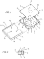
- the cassette according to the embodiment shown in FIG. 1 consists of a lower housing element 1, a housing cover 2 and a drawer 3.
- the lower housing element 1 comprises a compartment 4 intended to receive a disc (not shown), this compartment being delimited by three wall elements in an arc of a circle 5a, 5b, 5c.
- the bottom 6 of the lower housing element 1 comprises an opening 7, part of which 7a, delimited by an edge 7'a in an arc of a circle, is formed in the central part of the bottom 6 and is intended to allow the passage of a drive shaft for rotating the disc, when the cassette is placed in a disc reading device, in a known manner.
- the rest of the opening 7 constitutes a part 7b, delimited by two edges 7'b, intended to allow access to a disk reading device, for example an optical laser reading device (not shown) also belonging to this reading device.
- the location, dimensions and shape of the opening 7, as well as, more generally, the shape and external dimensions of the lower housing element 1, correspond to those of the models existing on the market for the kind of disc, for example, for CD-ROM discs and corresponding disc cassettes.
- the housing cover 2 is arranged so that it can be fixed, in a removable manner, to the lower housing element 1 by enclosing a disc (not shown) contained in the compartment 4.
- the fixing of the cover 2 on the element 1 is carried out by means of four hooking fingers 8 made up of strips projecting from the bottom 6 of the element 1 and inside of it, in the vicinity of each of its corners, parallel to the side walls 9 of the element 1.
- the end of each of these fingers 8 is provided with a claw 10 arranged so as to be able to hang on a flange 11 projecting into an opening 12 made in the vicinity of each of the corners of the cover 2, the release of each claw 10 to release the rim 11 when it is desired to separate the cover 2 from the lower element 1 which can be carried out by slight bending of the corresponding finger 8.
- a circle represented by a broken line in FIG. 1 indicates, in transparency, the location of an optional housing 13 on the underside 2b of the cover 2, not visible in FIG. 1.
- This housing 13, when it exists, is provided for retaining a rotary disc clamping element according to an arrangement identical or analogous to that of cassettes of the usual type.
- the rear side face 9 ′ of the lower casing element 1 has a recess 14 which makes it easier to identify the orientation of the cassette with a view to its correct insertion into the device for reading the disc.
- the drawer 3 is arranged to receive, by translation, as indicated in FIG. 1, the assembly constituted by the housing element 1, closed by its cover 2, and it comprises a bottom 15, two side walls 16 and a rear wall 17.
- a cutout 18, in an arc of a circle, formed in the edge front of the bottom 15, facilitates the handling of the housing element 1 when it is desired to remove it from the drawer 3.
- a housing (not shown) is provided in the upper face of the bottom 15 to receive a sheet or a plate. with instructions on how to use the cassette and / or disc, or any other kind of information.
- the parts 1, 2 and 3 constituting the cassette have very simple shapes. They can be produced in the form of plastic molding parts and the cost price of a cassette made up of these three parts is therefore very low.
- the cassette according to the embodiment shown in FIG. 3 is similar to that of FIG. 1. These two embodiments differ essentially in that, in the cassette of FIG. 3, the cover 2 'is assembled with the lower housing element 1' by means of a hinge. As seen in Fig. 4, this hinge is constituted by a thinned wall portion 21 which provides the transition between the front wall 22 of the housing element 1 and the cover 2 ', this element 1 and this cover 2' being advantageously made in one piece coming from plastic molding.
- Fig. 5 shows the relative arrangement of the functional elements of the cassette and of a disc, arranged to be used with this cassette, according to an embodiment of the cassette not provided with disc clamping element.
- the disc 23 is placed in the compartment 4, inside the lower case element 1, closed by its cover 2.
- the cover 2 does not have a housing intended to retain a disc clamping element, at the location corresponding to the latter which is indicated by the circle 13 in Figures 1 and 3, but simply a thinned part, also identified by the number 13 which prevents friction of the clamping element 24 against the inner surface of the cover 2 when the cassette is in the disc playback position.
- this clamping element 30 is constituted by a piece of circular shape, advantageously made of plastic, comprising an annular projection 31, the flat front surface 36 of which is intended to bear on the upper surface of the disc, in order to clamp it against the drive shaft of the rotating disc, as indicated below, and a central housing 32 in which is placed a circular plate 24 ', made of non-permanently magnetizable material.
- the clamping element 30 also has a peripheral rim 33 making it possible to retain the whole of the element 30 inside a housing 13, formed in the cover 2 of the cassette, while also ensuring it freedom of translation parallel to the axis of the drive shaft 26 (see Fig. 7) than freedom of movement in rotation about its axis, the maintenance of the element 30 inside the housing 13 being provided by collaboration of the rim 33 with a plurality of retention members 34 extending parallel to the surface of the cover in the direction of the center of an opening 35 allowing the passage of the annular projection 31.
- the positioning allowing the cassette to be removed, after reading the information recorded on the disc 23, is carried out in a similar manner to the case of the embodiment illustrated in FIG. 5.
- the housing 13 is not closed, on the outside of the cassette, by a thinned wall forming an integral part of the cover 2 as in the case of the embodiment of FIG. 6, but by a disc-shaped wall element 43 which is fixed on the cover 2, for example by bonding its peripheral part to a flange 44 formed for this purpose all around the external opening of the housing 13, after introduction of the clamping element 30 in this housing.
- the magnetizable plate 24 ′ can be placed very simply inside the central housing 32 of the body 30a of the clamping element 30, which advantageously consists of a piece of plastic molding. As illustrated by part 8 (b) of FIG. 8, the positioning of the magnetizable plate 24 ′ in the body 30a is effected by simple translation and the plate 24 ′ is fixed to the body 30a in any suitable manner, for example by gluing.
- Part 8 (a) of FIG. 8 shows the introduction of the element 30, previously provided with the magnetizable plate 24 ′, in the housing 13 of the cover 2 (produced in accordance with the embodiment illustrated in FIG. 6), by temporary deformation, so elastic, retention elements 34 of this housing when the rim 33 of the element 30 passes.
- Fig. 9 shows a variant of the embodiment of the disc 23 of FIG. 5.
- the clamping piece 24 of the disc 23 is fixed on the latter, not by gluing, but by clipping, by means of fingers 40, forming room from the upper surface of the disc 23, around the central opening of the latter, these fingers 40 being terminated by claws 41 arranged to bear on the edge 42 of the part 24 by securing it to the disc 23.
Abstract
Description
La présente invention concerne les cassettes à disque telles que celles que l'on utilise comme logement pour des disques servant de supports d'information et agencées de manière à permettre la lecture et/ou l'enregistrement des informations, alors que le disque est logé dans la cassette. L'invention a, plus particulièrement, pour objet une cassette à disque comprenant un élément de boîtier inférieur agencé pour servir de logement de disque, le fond de cet élément comportant une ouverture, dont une partie est destinée à permettre le passage d'un arbre d'entraînement du disque en rotation, cet arbre appartenant à un appareil de lecture du disque, et dont une autre partie est destinée à permettre l'accès d'un dispositif de lecture du disque, appartenant à ce même appareil, et un couvercle de boîtier agencé de manière à permettre de fermer ou d'ouvrir la cassette, en constituant une paroi principale en regard du fond de l'élément de boîtier inférieur.The present invention relates to disc cassettes such as those used as a housing for discs serving as information carriers and arranged so as to allow reading and / or recording of information, while the disc is housed in the cassette. The invention more particularly relates to a disc cassette comprising a lower casing element arranged to serve as a disc housing, the bottom of this element comprising an opening, a part of which is intended to allow the passage of a shaft drive disc in rotation, this shaft belonging to a disc reading device, and another part of which is intended to allow access to a disc reading device, belonging to this same device, and a cover housing arranged so as to allow the cassette to be closed or opened, constituting a main wall facing the bottom of the lower housing element.
L'invention peut notamment s'appliquer dans le cas où le disque en question est du type désigné habituellement par le terme de "disque compact" ou "CD" et, plus particulièrement, celui où il s'agit d'un disque support d'information désigné par le terme "CD-ROM" correspondant à l'abréviation de la dénomination anglaise "Compact Disc - Read Only Memory". Toutefois, l'invention n'est nullement limitée à ce type de disque.The invention can in particular be applied in the case where the disc in question is of the type usually designated by the term "compact disc" or "CD" and, more particularly, that in which it is a support disc. information designated by the term "CD-ROM" corresponding to the abbreviation of the English name "Compact Disc - Read Only Memory". However, the invention is in no way limited to this type of disc.
Les cassettes à disque de ce genre, de même que les disques destinés à être utilisés dans ces cassettes, sont agencés de manière à permettre leur utilisation dans des dispositifs de lecture et/ou d'enregistrement d'information produits par différents fabricants.Disc cassettes of this kind, as well as the discs intended for use in these cassettes, are arranged so as to allow their use in devices for reading and / or recording information produced by different manufacturers.
L'agencement des cassettes à disque usuel, pour disques du genre CD-ROM est relativement compliqué, bien que de telles cassettes soient réalisées à partir d'éléments de boîtier constitués de simples pièces venues de moulage en matières plastiques.The arrangement of conventional disc cassettes for CD-ROM type discs is relatively complicated, although such cassettes are made from housing elements consisting of simple molded plastic parts.
En effet, conformément à l'état antérieur de la technique, les cassettes pour disques CD-ROM comprennent un volet d'obturation mobile destiné à fermer l'ouverture pratiquée dans le fond de l'élément de boîtier inférieur, afin de protéger le disque contre le risque de détérioration mécanique et, également, pour imiter l'accès de poussières à l'intérieur de la cassette, lorsque le disque n'est pas en cours d'utilisation dans l'appareil de lecture. Ce volet d'obturation est muni d'un dispositif mécanique pour provoquer son effacement automatique, en dégageant ladite ouverture, lors de l'introduction de la cassette dans l'appareil de lecture et sa remise en position de fermeture, lorsque l'on retire la cassette de son logement récepteur, ménagé dans l'appareil de lecture. Un tel dispositif comporte généralement des leviers d'actionnement et au moins un ressort, il est donc relativement complexe, délicat et onéreux. La présence de ce dispositif augmente donc considérablement le prix de revient de ce genre de cassette à disque et elle entraîne, en outre, un risque non négligeable de défauts de fonctionnement, notamment lorsque la cassette atteint un état d'usure plus ou moins avancé.In fact, according to the prior art, cassettes for CD-ROM discs include a movable shutter intended to close the opening made in the bottom of the lower case element, in order to protect the disc. against the risk of mechanical deterioration and, also, to imitate the access of dust inside the cassette, when the disc is not in use in the reading device. This shutter is provided with a mechanical device to cause its automatic erasure, by releasing said opening, during the introduction of the cassette into the reading device and its return to the closed position, when it is removed. the cassette in its receiver housing, located in the reading device. Such a device generally comprises actuation levers and at least one spring, it is therefore relatively complex, delicate and expensive. The presence of this device therefore considerably increases the cost price of this type of disc cassette and it also entails a non-negligible risk of operating faults, in particular when the cassette reaches a more or less advanced state of wear.
D'autre part, également selon l'état antérieur de la technique, les cassettes à disques sont munies d'un élément de serrage du disque comportant généralement une pièce circulaire en matière plastique, dans laquelle est logée une plaque en matériau magnétique, cet élément de serrage étant destiné à être attiré vers la surface de l'extrémité antérieure aimantée de l'arbre d'entraînement en rotation du disque, en solidarisant le disque de cet arbre. Cet élément de serrage est maintenu dans un logement agence dans la paroi de la cassette venant en position opposée au fond de l'élément inférieur de boîtier, de manière à permettre la libre rotation de cet élément par rapport au boîtier, lorsque la cassette est placée dans l'appareil de lecture, l'arbre d'entraînement étant en prise avec le disque.On the other hand, also according to the prior art, the disc cassettes are provided with a disc clamping element generally comprising a circular piece of plastic material, in which is housed a plate made of magnetic material, this element clamping device being intended to be attracted towards the surface of the anterior magnetized end of the drive shaft for rotating the disc, by securing the disc to this shaft. This clamping element is held in a housing arranged in the wall of the cassette coming in position opposite the bottom of the lower housing element, so as to allow the free rotation of this element relative to the housing, when the cassette is placed in the reading device, the drive shaft being engaged with the disc.
La présence de cet élément de serrage en tant que partie constitutive des cassettes à disque constitue, bien entendu, un facteur supplémentaire d'élévation du coût de ce genre de cassette.The presence of this clamping element as a constituent part of disc cassettes constitutes, of course, an additional factor raising the cost of this type of cassette.
L'invention a précisément pour but de permettre de réduire, de manière importante, le prix de revient d'une cassette à disque, tout en éliminant le risque de défaut de fonctionnement mentionné ci-dessus.The object of the invention is precisely to make it possible to significantly reduce the cost price of a disc cassette, while eliminating the risk of malfunction mentioned above.
A cet effet, la cassette selon l'invention est caractérisée en ce que la cassette comprend également un tiroir agencé pour recevoir, de manière amovible, ledit élément de boîtier inférieur, fermé par ledit couvercle de boîtier, ce tiroir comportant un fond qui constitue une paroi fermant ladite ouverture du fond de l'élément de boîtier inférieur, lorsque ce dernier est placé dans ledit tiroir.To this end, the cassette according to the invention is characterized in that the cassette also comprises a drawer arranged to removably receive said lower housing element, closed by said housing cover, this drawer comprising a bottom which constitutes a wall closing said opening of the bottom of the lower casing element, when the latter is placed in said drawer.
Ainsi, dans la cassette selon l'invention, le volet d'obturation de l'ouverture du fond de l'élément de boîtier inférieur, ainsi que le mécanisme pour la manoeuvre de ce volet lors de l'introduction de la cassette dans l'appareil de lecture, sont supprimés et la cassette comprend simplement un tiroir ou élément de boîtier additionnel dans lequel il suffit d'introduire l'élément de boîtier inférieur, fermé par le couvercle de boîtier pour fermer ladite ouverture lorsque la cassette n'est pas en cours d'utilisation dans l'appareil de lecture, cette ouverture pouvant être dégagée par simple séparation de l'élément de boîtier additionnel du reste de la cassette, juste avant l'introduction de celle-ci dans l'appareil de lecture.Thus, in the cassette according to the invention, the shutter for closing the opening of the bottom of the element of the lower housing, as well as the mechanism for the operation of this shutter during the introduction of the cassette into the reading device, are eliminated and the cassette simply comprises a drawer or additional casing element into which it suffices to introduce the lower casing element, closed by the casing cover to close said opening when the cassette is not in during use in the reading device, this opening being able to be released by simple separation of the additional box element from the rest of the cassette, just before the introduction thereof into the reading device.
Ce tiroir peut être réalisé sous forme d'une pièce de forme simple, venue de moulage en matière plastique, et l'encombrement total de l'ensemble de la cassette, y compris ce tiroir ou élément additionnel, est à peine supérieur à celui d'une cassette de type usuel, le format de la partie de la cassette selon l'invention destinée à être introduite dans l'appareil de lecture restant, bien entendu, le même que celui des cassettes de type usuel.This drawer can be produced in the form of a piece of simple shape, coming from plastic molding, and the total size of the entire cassette, including this drawer or additional element, is barely greater than that of 'A cassette of the usual type, the format of the part of the cassette according to the invention intended to be introduced into the reading device remaining, of course, the same as that of the cassettes of the usual type.
D'autre part, la cassette selon l'invention n'est pas nécessairement munie de l'élément de serrage du disque mentionné plus haut, et elle peut être utilisée en relation avec un disque comprenant un élément de serrage de disque fixé sur le disque lui-même.On the other hand, the cassette according to the invention is not necessarily provided with the disc clamping element mentioned above, and it can be used in relation to a disc comprising a disc clamping element fixed on the disc. himself.
L'invention a également pour objet un tel disque destiné à être utilisé dans une cassette à disque non munie d'élément de serrage de disque.The invention also relates to such a disc intended to be used in a disc cassette not provided with disc clamping element.
On comprend donc que l'invention englobe aussi bien des formes d'exécution qui ne sont pas munies d'élément de serrage de disque, ces formes d'exécution, prévues pour être utilisées dans le cas où l'élément de serrage est fixé sur le disque lui-même, étant particulièrement simples et peu onéreuses puisqu'elles ne se composent que de deux ou trois pièces en matière plastique, de forme peu compliquée, que des formes d'exécution munies, de manière connue en soi, d'un élément de serrage du disque. Ces dernières formes d'exécution sont également moins onéreuses et plus tables que les cassettes à disque conformes à l'état antérieur, puisqu'elles sont exemptes du volet d'obturation et de son mécanisme de manoeuvre, comme indiqué plus haut.It is therefore understood that the invention also encompasses embodiments which are not provided with a disc clamping element, these embodiments, intended to be used in the case where the clamping element is fixed to the disc itself, being particularly simple and inexpensive since they consist only of two or three plastic parts, of uncomplicated shape, only embodiments provided, in a manner known per se, with a disc clamping element. These latter embodiments are also less expensive and more table than disc cassettes conforming to the prior state, since they are free from the shutter and its operating mechanism, as indicated above.
On va maintenant décrire, à titre d'exemples non limitatifs, des formes particulières d'exécution de la cassette selon l'invention, ainsi que d'un disque destiné à être utilisé dans cette cassette, en se référant au dessin annexé, dans lequel:
- La Fig. 1 est une vue en perspective montrant une première forme d'exécution de la cassette;
- La Fig. 2 est une vue en coupe montrant un détail de l'agencement de la cassette de la Fig. 1;
- La Fig. 3 est une vue en perspective montrant une deuxième forme d'exécution de la cassette;
- La Fig. 4 est une vue en coupe montrant un détail de l'agencement de la cassette de la Fig. 3;
- La Fig. 5 est une vue en coupe montrant la disposition relative de la cassette selon une forme d'exécution non munie d'élément de serrage de disque, d'un disque comprenant un élément de serrage fixé sur le disque lui-même et de l'arbre d'entraînement du disque en rotation, lorsque la cassette est en position de lecture dans un appareil de lecture des informations enregistrées sur le disque;
- La Fig. 6 est une vue en coupe montrant l'agencement d'un élément de serrage du disque et sa disposition dans un logement ménagé dans le couvercle de boîtier, selon une forme d'exécution de la cassette selon l'invention, munie d'un tel élément de serrage;
- La Fig. 7 est une vue en coupe montrant la disposition relative de la cassette selon une forme d'exécution de cette cassette munie d'un élément de serrage de disque, et d'un disque en prise avec l'arbre d'entraînement du disque, lorsque la cassette est en position de lecture dans un appareil de lecture;
- La Fig. 8 est une vue en coupe, en trois parties, illustrant la fabrication d'un élément de serrage de disque, agencé de manière à pouvoir être utilisé dans la cassette selon la Fig. 7 et la mise en place de cet élément dans cette cassette; et
- La Fig. 9 est une vue en coupe montrant une variante du disque destiné à être utilisé dans la cassette de la Fig. 5.
- Fig. 1 is a perspective view showing a first embodiment of the cassette;
- Fig. 2 is a sectional view showing a detail of the arrangement of the cassette of FIG. 1;
- Fig. 3 is a perspective view showing a second embodiment of the cassette;
- Fig. 4 is a sectional view showing a detail of the arrangement of the cassette of FIG. 3;
- Fig. 5 is a sectional view showing the relative arrangement of the cassette according to an embodiment not provided with a disc clamping element, a disc comprising a clamping element fixed to the disc itself and the shaft driving the disc in rotation, when the cassette is in the reading position in a device for reading the information recorded on the disc;
- Fig. 6 is a sectional view showing the arrangement of a disc clamping element and its arrangement in a housing provided in the housing cover, according to an embodiment of the cassette according to the invention, provided with such a clamping element;
- Fig. 7 is a sectional view showing the relative arrangement of the cassette according to an embodiment of this cassette provided with a disc clamping element, and with a disc engaged with the drive shaft of the disc, when the cassette is in the reading position in a reading device;
- Fig. 8 is a sectional view, in three parts, illustrating the manufacture of a disc clamping element, arranged so that it can be used in the cassette according to FIG. 7 and the positioning of this element in this cassette; and
- Fig. 9 is a sectional view showing a variant of the disc intended for use in the cassette of FIG. 5.
La cassette conforme à la forme d'exécution représentée à la Fig. 1 se compose d'un élément de boîtier inférieur 1, d'un couvercle de boîtier 2 et d'un tiroir 3.The cassette according to the embodiment shown in FIG. 1 consists of a lower housing element 1, a
L'élément de boîtier inférieur 1 comprend un compartiment 4 destiné à recevoir un disque (non représenté), ce compartiment étant délimité par trois éléments de parois en arc de cercle 5a, 5b, 5c.The lower housing element 1 comprises a compartment 4 intended to receive a disc (not shown), this compartment being delimited by three wall elements in an arc of a
Le fond 6 de l'élément de boîtier inférieur 1 comprend une ouverture 7, dont une partie 7a, délimitée par un bord 7'a en arc de cercle, est ménagée dans la partie centrale du fond 6 et est destinée à permettre le passage d'un arbre d'entraînement en rotation du disque, lorsque la cassette est placée dans un appareil de lecture du disque, de manière connue. Le reste de l'ouverture 7 constitue une partie 7b, délimitée par deux bords 7'b, destinée à permettre l'accès d'un dispositif de lecture du disque, par exemple un dispositif de lecture optique à laser (non représenté) appartenant également à cet appareil de lecture.The
L'emplacement, les dimensions et la forme de l'ouverture 7, de même que, plus généralement, la forme et les dimensions extérieures de l'élément de boîtier inférieur 1, correspondent à ceux des modèles existant sur le marché pour le genre de disque dont il s'agit, par exemple, pour les disques CD-ROM et les cassettes à disque correspondantes.The location, dimensions and shape of the
Le couvercle de boîtier 2 est agencé de manière à pouvoir être fixé, de manière amovible, sur l'élément de boîtier inférieur 1 en enfermant un disque (non représenté) contenu dans le compartiment 4.The
La fixation du couvercle 2 sur l'élément 1 s'effectue au moyen de quatre doigts d'accrochage 8 constitués de lamelles en saillie à partir du fond 6 de l'élément 1 et à l'intérieur de celui-ci, au voisinage de chacun de ses coins, parallèlement aux parois latérales 9 de l'élément 1. Comme représenté à la Fig. 2, l'extrémité de chacun de ces doigts 8 est munie d'une griffe 10 agencée de manière à pouvoir s'accrocher sur un rebord 11 en saillie dans une ouverture 12 pratiquée au voisinage de chacun des coins du couvercle 2, le décrochage de chaque griffe 10 pour dégager le rebord 11 lorsqu'on désire séparer le couvercle 2 de l'élément inférieur 1 pouvant s'effectuer par légère flexion du doigt 8 correspondant.The fixing of the
Un cercle représenté par une ligne discontinue à la Fig. 1 indique, en transparence, l'emplacement d'un logement 13, facultatif, sur la face inférieure 2b du couvercle 2, non visible à la Fig. 1. Ce logement 13, lorsqu'il existe, est prévu pour retenir un élément rotatif de serrage de disque selon un agencement identique ou analogue à celui des cassettes de type usuel.A circle represented by a broken line in FIG. 1 indicates, in transparency, the location of an
Une forme d'exécution particulière de la cassette selon l'invention, munie d'un tel logement, sera décrite plus loin.A particular embodiment of the cassette according to the invention, provided with such a housing, will be described later.
La face latérale arrière 9' de l'élément de boîtier inférieur 1 présente un renfoncement 14 qui facilite le repérage de l'orientation de la cassette en vue de son introduction correcte dans l'appareil de lecture du disque.The
Le tiroir 3 est agencé pour recevoir, par translation, comme indiqué à la Fig. 1, l'ensemble constitué par l'élément de boîtier 1, fermé par son couvercle 2, et il comprend un fond 15, deux parois latérales 16 et une paroi arrière 17. Une découpure 18, en arc de cercle, pratiquée dans le bord antérieur du fond 15, facilite la prise en main de l'élément de boîtier 1 lorsque l'on désire le retirer du tiroir 3.The drawer 3 is arranged to receive, by translation, as indicated in FIG. 1, the assembly constituted by the housing element 1, closed by its
Deux rebords latéraux 19, s'étendant à partir du bord libre des parois latérales 16, sur une partie de la longueur de ce bord, et un rebord arrière 20, s'étendant à partir du bord libre de la paroi arrière 18, permettent de retenir l'ensemble formé par l'élément de boîtier 1 et son couvercle 2 lorsqu'ils sont placés dans le tiroir 3.Two
On comprend que le tiroir 3, qui ferme entièrement l'ouverture 7 lorsque la cassette n'est pas en position d'utilisation dans l'appareil de lecture du disque, assure une protection efficace du disque.It is understood that the drawer 3, which completely closes the
Avantageusement, un logement (non représenté) est ménagé dans la face supérieure du fond 15 pour recevoir une feuille ou une plaque portant des instructions concernant le mode d'emploi de la cassette et/ou du disque, ou tout autre genre d'indications.Advantageously, a housing (not shown) is provided in the upper face of the
On voit que les pièces 1, 2 et 3, constitutives de la cassette, ont des formes très simples. Elles peuvent être réalisées sous forme de pièces venues de moulage en matière plastique et le prix de revient d'une cassette constituée par ces trois pièces est donc très faible.We see that the
La cassette selon la forme d'exécution représentée à la Fig. 3 est similaire à celle de la Fig. 1. Ces deux formes d'exécution diffèrent essentiellement en ce que, dans la cassette de la Fig. 3, le couvercle 2' est assemblé avec l'élément de boîtier inférieur 1' au moyen d'une charnière. Comme on le voit à la Fig. 4, cette charnière est constituée par une partie de paroi amincie 21 qui assure la transition entre la paroi antérieure 22 de l'élément de boîtier 1 et le couvercle 2', cet élément 1 et ce couvercle 2' étant avantageusement réalisés en une seule pièce venue de moulage en matière plastique.The cassette according to the embodiment shown in FIG. 3 is similar to that of FIG. 1. These two embodiments differ essentially in that, in the cassette of FIG. 3, the cover 2 'is assembled with the lower housing element 1' by means of a hinge. As seen in Fig. 4, this hinge is constituted by a thinned
La Fig. 5 montre la disposition relative des éléments fonctionnels de la cassette et d'un disque, agencé pour être utilisé avec cette cassette, selon une forme d'exécution de la cassette non munie d'élément de serrage de disque. Comme on le voit à la Fig. 5, qui représente la disposition des éléments de la cassette lorsque celle-ci est placée dans un appareil de lecture du disque, le disque 23 est placé dans le compartiment 4, à l'intérieur de l'élément de boîtier inférieur 1, fermé par son couvercle 2. Une pièce circulaire 24, ayant la forme d'une cuvette présentant un rebord circulaire 25 plat et dont le fond est constitué par une plaquette 24a en un matériau aimantable de manière non permanente, telle que le fer doux, est collée sur la partie centrale du disque 23, concentriquement à celui-ci, avec le rebord 25 appliqué tout autour de l'ouverture centrale du disque 23.Fig. 5 shows the relative arrangement of the functional elements of the cassette and of a disc, arranged to be used with this cassette, according to an embodiment of the cassette not provided with disc clamping element. As seen in Fig. 5, which represents the arrangement of the elements of the cassette when the latter is placed in a device for reading the disc, the
Lorsque, de manière connue en soi, on place la surface frontale 27 de l'extrémité aimantée de l'arbre 26 d'entraînement en rotation du disque 23 dans l'ouverture centrale du disque 23, dans la position représentée à la Fig. 5, la partie centrale plate aimantable 24a de la pièce 24 est attirée par la surface 27 en solidarisant le disque 23 de l'arbre 26. On peut ainsi faire tourner le disque 23 au moyen de l'arbre 26.When, in a manner known per se, the
Pour éviter qu'une surpression d'air ne se produise lors de l'introduction de l'extrémité de l'arbre 26 dans l'ouverture centrale du disque 23, en entraînant un risque de déplacement intempestif de la pièce 24, ainsi que pour éviter le risque d'effet de ventouse lors de l'extraction de l'extrémité de l'arbre 26, une petite ouverture 29, servant d'évent, est ménagée au centre de la pièce 24.To prevent an overpressure of air from occurring during the introduction of the end of the
Après lecture des informations enregistrées sur le disque 23, lorsque l'on désire retirer la cassette de l'appareil de lecture du disque, il suffit de tirer vers le bas l'arbre d'entraînement 26 en exerçant au début de ce mouvement une force supérieure à la force d'attraction de la partie centrale 24 a de la pièce 24 par la surface frontale 27 de l'arbre 26, sur une distance suffisante pour que ce dernier sorte complètement de l'ouverture 7 du fond 6 de l'élément de boîtier inférieur 1. Le disque 23 vient alors se poser sur la surface du fond 6 de l'élément 1 et le retrait de la cassette hors de son logement dans l'appareil de lecture devient possible.After reading the information recorded on the
Comme on le voit à la Fig. 5, le couvercle 2 ne présente pas de logement destiné à retenir un élément de serrage du disque, à l'emplacement correspondant à celui-ci qui est indiqué par le cercle 13 aux Figures 1 et 3, mais simplement une partie amincie, également repérée par le chiffre 13 qui évite le frottement de l'élément de serrage 24 contre la surface intérieure du couvercle 2 lorsque la cassette est dans la position de lecture de disque.As seen in Fig. 5, the
Comme on le voit à la Fig. 6, conformément à une forme d'exécution de la cassette munie d'un élément de serrage du disque, cet élément de serrage 30 est constitué par une pièce de forme circulaire, avantageusement réalisée en matière plastique, comprenant une projection annulaire 31, dont la surface frontale plane 36 est destinée à prendre appui sur la surface supérieure du disque, afin de le serrer contre l'arbre d'entraînement du disque en rotation, comme indiqué plus loin, et un logement central 32 dans lequel est placée une plaquette circulaire 24', en matériau aimantable de manière non permanente.As seen in Fig. 6, in accordance with an embodiment of the cassette provided with a disc clamping element, this clamping
L'élément de serrage 30 présente, en outre, un rebord périphérique 33 permettant de retenir l'ensemble de l'élément 30 à l'intérieur d'un logement 13, ménagée dans le couvercle 2 de la cassette, tout en lui assurant aussi bien une liberté de translation parallèlement à l'axe de l'arbre d'entraînement 26 (voir Fig. 7) qu'une liberté de déplacement en rotation autour de son axe, le maintien de l'élément 30 à l'intérieur du logement 13 étant assuré par collaboration du rebord 33 avec une pluralité d'organes de rétention 34 s'étendant parallèlement à la surface du couvercle en direction du centre d'une ouverture 35 permettant le passage de la projection annulaire 31.The clamping
Comme on le voit à la Fig. 7, lorsque la cassette correspondant à une forme d'exécution similaire à celle dont un détail est illustré à la Fig. 6, est placée dans l'appareil de lecture du disque, l'arbre 26 d'entraînement en rotation du disque 23 étant engagé dans l'ouverture centrale de celui-ci, la pièce aimantable 24' est attirée par la surface frontale 27 de l'extrémité aimantée de l'arbre 26, de manière analogue au cas de la forme d'exécution illustrée à la Fig. 5. La surface frontale plane 36 de la projection annulaire 31 vient alors s'appuyer fortement contre la surface supérieure du disque 23, autour de l'ouverture centrale de ce dernier, en le solidarisant de l'arbre 26.As seen in Fig. 7, when the cassette corresponding to an embodiment similar to that of which a detail is illustrated in FIG. 6, is placed in the disc reading device, the
La mise en position permettant le retrait de la cassette, après lecture des informations enregistrées sur le disque 23, s'effectue de manière analogue au cas de la forme d'exécution illustrée à la Fig. 5.The positioning allowing the cassette to be removed, after reading the information recorded on the
Il est à noter que, dans la forme d'exécution représentée à la Fig. 7, le logement 13 n'est pas fermé, du côté extérieur de la cassette, par une paroi amincie faisant partie intégrante du couvercle 2 comme dans le cas de la forme d'exécution de la Fig. 6, mais par un élément de paroi 43 en forme de disque que l'on fixe sur le couvercle 2, par exemple par collage de sa partie périphérique sur un rebord 44 ménagé à cet effet tout autour de l'ouverture extérieure du logement 13, après introduction de l'élément de serrage 30 dans ce logement.It should be noted that, in the embodiment shown in FIG. 7, the
Comme on le voit à la Fig. 8, la plaquette aimantable 24' peut être mise en place de manière très simple à l'intérieur du logement central 32 du corps 30a de l'élément de serrage 30, qui est avantageusement constitué par une pièce venue de moulage en matière plastique. Comme illustré par la partie 8 (b) de la Fig. 8, la mise en place de la plaquette aimantable 24' dans le corps 30a s effectue par simple translation et la plaquette 24' est fixée sur le corps 30a de toute manière appropriée, par exemple par collage.As seen in Fig. 8, the
La partie 8 (a) de la Fig. 8 montre l'introduction de l'élément 30, préalablement muni de la plaquette aimantable 24', dans le logement 13 du couvercle 2 (réalisé conformément à la forme d'exécution illustrée à la Fig. 6), par déformation temporaire, de manière élastique, des éléments de rétention 34 de ce logement au passage du rebord 33 de l'élément 30.Part 8 (a) of FIG. 8 shows the introduction of the
La Fig. 9 montre une variante de la forme d'exécution du disque 23 de la Fig. 5. Selon cette variante, la pièce de serrage 24 du disque 23 est fixée sur celui-ci, non pas par collage, mais par clipsage, au moyen de doigts 40, faisant salle à partir de la surface supérieure du disque 23, autour de l'ouverture centrale de ce dernier, ces doigts 40 étant terminés par des griffes 41 agencées pour prendre appui sur le bord 42 de la pièce 24 en la solidarisant du disque 23.Fig. 9 shows a variant of the embodiment of the
Claims (9)
Applications Claiming Priority (2)
| Application Number | Priority Date | Filing Date | Title |
|---|---|---|---|
| CH1565/92 | 1992-05-15 | ||
| CH156592A CH686538A5 (en) | 1992-05-15 | 1992-05-15 | Cassette drive. |
Publications (2)
| Publication Number | Publication Date |
|---|---|
| EP0570342A1 true EP0570342A1 (en) | 1993-11-18 |
| EP0570342B1 EP0570342B1 (en) | 1997-05-02 |
Family
ID=4213399
Family Applications (1)
| Application Number | Title | Priority Date | Filing Date |
|---|---|---|---|
| EP19930810341 Expired - Lifetime EP0570342B1 (en) | 1992-05-15 | 1993-05-11 | Disc cartridge |
Country Status (4)
| Country | Link |
|---|---|
| EP (1) | EP0570342B1 (en) |
| JP (1) | JPH0628810A (en) |
| CH (1) | CH686538A5 (en) |
| DE (1) | DE69310263T2 (en) |
Cited By (4)
| Publication number | Priority date | Publication date | Assignee | Title |
|---|---|---|---|---|
| EP0669615A2 (en) * | 1994-02-28 | 1995-08-30 | Hokko Kabushiki Kaisha | Disc case |
| EP0793230A2 (en) * | 1996-02-27 | 1997-09-03 | CD Plant Tecval S.A. | Disc cartridge with disc locking mechanism |
| EP0801794A1 (en) * | 1994-03-18 | 1997-10-22 | Opticord, Inc. | Protective cartridge for rewritable optical disk |
| EP2145832A1 (en) * | 2008-07-16 | 2010-01-20 | Siemens Milltronics Process Instruments Inc. | Hinged packaging container |
Families Citing this family (1)
| Publication number | Priority date | Publication date | Assignee | Title |
|---|---|---|---|---|
| US6243350B1 (en) * | 1996-05-01 | 2001-06-05 | Terastor Corporation | Optical storage systems with flying optical heads for near-field recording and reading |
Citations (10)
| Publication number | Priority date | Publication date | Assignee | Title |
|---|---|---|---|---|
| US4185313A (en) * | 1978-09-25 | 1980-01-22 | Magnetic Peripherals Inc. | Disc memory module dust shield |
| US4194228A (en) * | 1978-10-11 | 1980-03-18 | Magnetic Peripherals Inc. | Magnetic disc housing with means to prevent radial disc shift |
| US4471397A (en) * | 1983-07-28 | 1984-09-11 | Eastman Kodak Company | Magnetic disk cartridge |
| GB2173631A (en) * | 1985-04-09 | 1986-10-15 | Nikkodo Company Limited | Disc case |
| EP0230695A1 (en) * | 1985-12-24 | 1987-08-05 | GPT Axxicon B.V. | Disc-shaped information carrier having an insert piece provided with a central bore |
| US4748530A (en) * | 1983-01-24 | 1988-05-31 | Magnetic Peripherals, Inc. | Disk cover collar |
| EP0270182A2 (en) * | 1986-12-01 | 1988-06-08 | Optical Storage International Holland | Information carrier |
| EP0277809A1 (en) * | 1987-02-02 | 1988-08-10 | Sony Corporation | Disc cartridges |
| EP0319301A2 (en) * | 1987-12-01 | 1989-06-07 | Mitsui Petrochemical Industries, Ltd. | Information recording discs |
| EP0370690A2 (en) * | 1988-11-22 | 1990-05-30 | Philip Yung Tak Lam | A video and/or audio cassette assembly |
-
1992
- 1992-05-15 CH CH156592A patent/CH686538A5/en not_active IP Right Cessation
-
1993
- 1993-05-11 EP EP19930810341 patent/EP0570342B1/en not_active Expired - Lifetime
- 1993-05-11 DE DE1993610263 patent/DE69310263T2/en not_active Expired - Fee Related
- 1993-05-14 JP JP13642693A patent/JPH0628810A/en active Pending
Patent Citations (10)
| Publication number | Priority date | Publication date | Assignee | Title |
|---|---|---|---|---|
| US4185313A (en) * | 1978-09-25 | 1980-01-22 | Magnetic Peripherals Inc. | Disc memory module dust shield |
| US4194228A (en) * | 1978-10-11 | 1980-03-18 | Magnetic Peripherals Inc. | Magnetic disc housing with means to prevent radial disc shift |
| US4748530A (en) * | 1983-01-24 | 1988-05-31 | Magnetic Peripherals, Inc. | Disk cover collar |
| US4471397A (en) * | 1983-07-28 | 1984-09-11 | Eastman Kodak Company | Magnetic disk cartridge |
| GB2173631A (en) * | 1985-04-09 | 1986-10-15 | Nikkodo Company Limited | Disc case |
| EP0230695A1 (en) * | 1985-12-24 | 1987-08-05 | GPT Axxicon B.V. | Disc-shaped information carrier having an insert piece provided with a central bore |
| EP0270182A2 (en) * | 1986-12-01 | 1988-06-08 | Optical Storage International Holland | Information carrier |
| EP0277809A1 (en) * | 1987-02-02 | 1988-08-10 | Sony Corporation | Disc cartridges |
| EP0319301A2 (en) * | 1987-12-01 | 1989-06-07 | Mitsui Petrochemical Industries, Ltd. | Information recording discs |
| EP0370690A2 (en) * | 1988-11-22 | 1990-05-30 | Philip Yung Tak Lam | A video and/or audio cassette assembly |
Cited By (8)
| Publication number | Priority date | Publication date | Assignee | Title |
|---|---|---|---|---|
| EP0669615A2 (en) * | 1994-02-28 | 1995-08-30 | Hokko Kabushiki Kaisha | Disc case |
| EP0669615A3 (en) * | 1994-02-28 | 1996-01-24 | Hokko Kabushiki Kaisha | Disc case. |
| EP0801794A1 (en) * | 1994-03-18 | 1997-10-22 | Opticord, Inc. | Protective cartridge for rewritable optical disk |
| EP0801794A4 (en) * | 1994-03-18 | 1997-12-17 | Opticord Inc | Protective cartridge for rewritable optical disk |
| EP0793230A2 (en) * | 1996-02-27 | 1997-09-03 | CD Plant Tecval S.A. | Disc cartridge with disc locking mechanism |
| EP0793230A3 (en) * | 1996-02-27 | 1998-01-07 | CD Plant Tecval S.A. | Disc cartridge with disc locking mechanism |
| EP2145832A1 (en) * | 2008-07-16 | 2010-01-20 | Siemens Milltronics Process Instruments Inc. | Hinged packaging container |
| US8061553B2 (en) | 2008-07-16 | 2011-11-22 | Siemens Milltronics Process Instruments, Inc. | Hinged packaging container |
Also Published As
| Publication number | Publication date |
|---|---|
| DE69310263T2 (en) | 1997-12-18 |
| DE69310263D1 (en) | 1997-06-05 |
| EP0570342B1 (en) | 1997-05-02 |
| CH686538A5 (en) | 1996-04-15 |
| JPH0628810A (en) | 1994-02-04 |
Similar Documents
| Publication | Publication Date | Title |
|---|---|---|
| EP0035933A1 (en) | Cartridge for an optical disk | |
| FR2488715A1 (en) | FLEXIBLE MAGNETIC DISC CASSETTE AND RECORDING AND / OR REPRODUCING APPARATUS USING SUCH A DISK | |
| FR2512253A1 (en) | MAGNETIC DISC CASSETTE | |
| FR2475268A1 (en) | CASE FOR DISC-SHAPED RECORDING MEDIUM | |
| EP0004523B1 (en) | Case for cassette boxes | |
| FR2535099A1 (en) | FLEXIBLE MAGNETIC RECORDING AND / OR REPRODUCING APPARATUS | |
| EP0177415B1 (en) | Box for the storage, presentation and selection of floppy disks or other magnetic carriers | |
| EP0570342B1 (en) | Disc cartridge | |
| FR2698709A1 (en) | Disk loader. | |
| EP1003171A1 (en) | Cartridge for data carrier | |
| EP1410393B1 (en) | Cases for one or several laser discs and means for classifying same | |
| FR2767955A1 (en) | A CARTRIDGE HOLDING MECHANISM FOR A REMOVABLE CARTRIDGE READER | |
| WO2006045757A1 (en) | Plate and box for at least one pair of compact disks | |
| EP1559103B1 (en) | Package for a disc-shaped digital recording medium | |
| EP0624873A1 (en) | System which allows the correct loading of cassettes in an input room of a reading and/or writing equipment | |
| FR2537320A1 (en) | Cassette for optical disc | |
| FR2471108A1 (en) | DEVICE IN A VIDEO DRIVE TO IDENTIFY THE FACE OF A DISK | |
| FR2698710A1 (en) | Disc loader. | |
| FR2767954A1 (en) | SYSTEM FOR MOUNTING A DATA SUPPORT HUB TO MINIMIZE TRANSLATION FOLLOWING THE Z AXIS | |
| FR2727237A1 (en) | SHUTTERING MECHANISM FOR SHUTTING THE OPENING OF A DRIVE MODULE | |
| EP0783166B1 (en) | Checking and centering device for cassette loading | |
| JP3087630U (en) | Disk drive device | |
| FR2829866A1 (en) | STORAGE BOX FOR OPTICAL DISC | |
| EP0736868A1 (en) | Apparatus for detection of a cassette | |
| JP2000113629A (en) | Disk cartridge |
Legal Events
| Date | Code | Title | Description |
|---|---|---|---|
| PUAI | Public reference made under article 153(3) epc to a published international application that has entered the european phase |
Free format text: ORIGINAL CODE: 0009012 |
|
| AK | Designated contracting states |
Kind code of ref document: A1 Designated state(s): DE FR GB IT |
|
| 17P | Request for examination filed |
Effective date: 19931124 |
|
| 17Q | First examination report despatched |
Effective date: 19940225 |
|
| RAP1 | Party data changed (applicant data changed or rights of an application transferred) |
Owner name: CD PLANT TECVAL S.A. |
|
| GRAG | Despatch of communication of intention to grant |
Free format text: ORIGINAL CODE: EPIDOS AGRA |
|
| GRAH | Despatch of communication of intention to grant a patent |
Free format text: ORIGINAL CODE: EPIDOS IGRA |
|
| GRAH | Despatch of communication of intention to grant a patent |
Free format text: ORIGINAL CODE: EPIDOS IGRA |
|
| GRAA | (expected) grant |
Free format text: ORIGINAL CODE: 0009210 |
|
| AK | Designated contracting states |
Kind code of ref document: B1 Designated state(s): DE FR GB IT |
|
| REF | Corresponds to: |
Ref document number: 69310263 Country of ref document: DE Date of ref document: 19970605 |
|
| GBT | Gb: translation of ep patent filed (gb section 77(6)(a)/1977) |
Effective date: 19970801 |
|
| PLBE | No opposition filed within time limit |
Free format text: ORIGINAL CODE: 0009261 |
|
| STAA | Information on the status of an ep patent application or granted ep patent |
Free format text: STATUS: NO OPPOSITION FILED WITHIN TIME LIMIT |
|
| 26N | No opposition filed | ||
| REG | Reference to a national code |
Ref country code: GB Ref legal event code: IF02 |
|
| PGFP | Annual fee paid to national office [announced via postgrant information from national office to epo] |
Ref country code: GB Payment date: 20030428 Year of fee payment: 11 |
|
| PGFP | Annual fee paid to national office [announced via postgrant information from national office to epo] |
Ref country code: FR Payment date: 20030512 Year of fee payment: 11 |
|
| PGFP | Annual fee paid to national office [announced via postgrant information from national office to epo] |
Ref country code: DE Payment date: 20030514 Year of fee payment: 11 |
|
| PG25 | Lapsed in a contracting state [announced via postgrant information from national office to epo] |
Ref country code: GB Free format text: LAPSE BECAUSE OF NON-PAYMENT OF DUE FEES Effective date: 20040511 |
|
| PG25 | Lapsed in a contracting state [announced via postgrant information from national office to epo] |
Ref country code: DE Free format text: LAPSE BECAUSE OF NON-PAYMENT OF DUE FEES Effective date: 20041201 |
|
| GBPC | Gb: european patent ceased through non-payment of renewal fee |
Effective date: 20040511 |
|
| PG25 | Lapsed in a contracting state [announced via postgrant information from national office to epo] |
Ref country code: FR Free format text: LAPSE BECAUSE OF NON-PAYMENT OF DUE FEES Effective date: 20050131 |
|
| REG | Reference to a national code |
Ref country code: FR Ref legal event code: ST |
|
| PG25 | Lapsed in a contracting state [announced via postgrant information from national office to epo] |
Ref country code: IT Free format text: LAPSE BECAUSE OF NON-PAYMENT OF DUE FEES Effective date: 20050511 |