EP0570853A2 - Tape duplicating system - Google Patents
Tape duplicating system Download PDFInfo
- Publication number
- EP0570853A2 EP0570853A2 EP93107844A EP93107844A EP0570853A2 EP 0570853 A2 EP0570853 A2 EP 0570853A2 EP 93107844 A EP93107844 A EP 93107844A EP 93107844 A EP93107844 A EP 93107844A EP 0570853 A2 EP0570853 A2 EP 0570853A2
- Authority
- EP
- European Patent Office
- Prior art keywords
- tape
- medium
- peripheral surface
- guide means
- slave
- Prior art date
- Legal status (The legal status is an assumption and is not a legal conclusion. Google has not performed a legal analysis and makes no representation as to the accuracy of the status listed.)
- Withdrawn
Links
Images


Classifications
-
- G—PHYSICS
- G11—INFORMATION STORAGE
- G11B—INFORMATION STORAGE BASED ON RELATIVE MOVEMENT BETWEEN RECORD CARRIER AND TRANSDUCER
- G11B5/00—Recording by magnetisation or demagnetisation of a record carrier; Reproducing by magnetic means; Record carriers therefor
- G11B5/86—Re-recording, i.e. transcribing information from one magnetisable record carrier on to one or more similar or dissimilar record carriers
- G11B5/865—Re-recording, i.e. transcribing information from one magnetisable record carrier on to one or more similar or dissimilar record carriers by contact "printing"
-
- G—PHYSICS
- G11—INFORMATION STORAGE
- G11B—INFORMATION STORAGE BASED ON RELATIVE MOVEMENT BETWEEN RECORD CARRIER AND TRANSDUCER
- G11B15/00—Driving, starting or stopping record carriers of filamentary or web form; Driving both such record carriers and heads; Guiding such record carriers or containers therefor; Control thereof; Control of operating function
- G11B15/18—Driving; Starting; Stopping; Arrangements for control or regulation thereof
- G11B15/43—Control or regulation of mechanical tension of record carrier, e.g. tape tension
-
- G—PHYSICS
- G11—INFORMATION STORAGE
- G11B—INFORMATION STORAGE BASED ON RELATIVE MOVEMENT BETWEEN RECORD CARRIER AND TRANSDUCER
- G11B15/00—Driving, starting or stopping record carriers of filamentary or web form; Driving both such record carriers and heads; Guiding such record carriers or containers therefor; Control thereof; Control of operating function
- G11B15/60—Guiding record carrier
- G11B15/605—Guiding record carrier without displacing the guiding means
- G11B15/607—Pneumatic guiding
Definitions
- This invention relates to apparatus for, and methods of, transferring visual and audio information on a master tape to a slave tape. More particularly, this invention relates to apparatus for, and methods of, transferring visual and audio information in magnetic form on a master tape to a thermomagnetic layer on a slave tape. The invention also relates to a master or slave tape with properties individual to the apparatus and methods of this invention.
- Visual and audio information is often stored on a tape for playback at a subsequent time.
- visual and audio information relating to popular motion pictures is stored on tapes.
- These tapes are rented or sold at neighborhood stores.
- a popular movie such as "Batman" or a movie winning an Academy Award has millions of taped copies distributed to satisfy the demands of purchasers and renters. Substantially all of these taped copies have to be made available at a pre-selected release date in order to satisfy the pent-up demand of viewers for such taped copies.
- the demand for movie rentals and sales is great, the demand still seems to be increasing significantly from year to year.
- Visual and audio information on tapes is not only provided in the form of movies for entertainment. It is also provided in large volume for business purposes. For example, large corporations deliver messages in the form of tapes to their sales personnel to acquaint such sales personnel with the construction, operation and advantages of new products. Since large corporations employ large numbers of sales copies, many copies of such messages have to be prepared for distribution to their sales personnel.
- the visual and audio information on most tapes is in magnetic form.
- information in magnetic form can be relatively easily and inexpensively reproduced.
- most reproducing apparatus in the home use magnetic heads to read the information recorded magnetically on the tapes when the tapes are inserted into such apparatus.
- tapes with information recorded in magnetic form are less expensive to reproduce than tapes in other forms such as in optical form.
- thermomagnetic layer on the tape.
- the thermomagnetic layer may be formed from a suitable material such as chromium dioxide.
- the thermomagnetic layer has a Curie temperature at or above which any magnetic information on the tape is destroyed and below which magnetic information can be recorded on the tape.
- Thermomagnetic tape is advantageous because information can be recorded on the thermomagnetic tape at a temperature at or somewhat above the Curie temperature by pressing a master tape against the thermomagnetic layer on the slave tape at such a temperature. This causes the surface of the thermomagnetic layer to become cooled to a temperature below the Curie temperature by contact with the cool surface of the master tape.
- thermomagnetic layer cools to a temperature below the Curie temperature
- the magnetic information on the master tape becomes transferred to the thermomagnetic layer on the slave tape.
- the information on the master tape thus becomes transferred in mirror form to the thermomagnetic layer on the slave tape without having to use any magnetic heads to write information on the slave tape.
- thermomagnetic layer on a slave tape There is at least one apparatus now in use for transferring information in magnetic form on a master tape to a thermomagnetic layer on a slave tape. Although this apparatus is fast, it is large, cumbersome and expensive, and it requires excessive electrical power. It is accordingly not economical to transfer images from a master tape to a slave tape by using the apparatus.
- a master tape moves between first supply and take-up reels over a pinch roller.
- a slave tape moves between second supply and take-up reels over a capstan.
- First and second guides can be respectively constructed and adjustably positioned to regulate the movement of the master and slave tapes to aligned positions on the pinch roller and the capstan.
- a heater disposed between the capstan and the second guide heats only a thermomagnetic layer on the slave tape to at least the Curie temperature. The heater is adjustable in position to facilitate the movement of the slave tape to the aligned position on the capstan.
- a brake shoe between the capstan and the second supply reel controls the tape tension and damps any variations in the tension of the slave tape.
- a second brake shoe between the pinch roller and the first supply reel controls the tape tension and damps any variations in the tension of the master tape.
- the pinch roller is movable to a first position and locked in position relative to the capstan, in which it abuts the capstan to facilitate the transfer of magnetic information from the master tape to the slave tape. In this disposition, the pinch roller locks the heater in a fixed position relative to the capstan.
- the pinch roller and the associated guide are movable to a second position displaced from the capstan to facilitate the disposition of the master tape on the pinch roller.
- the heater is pivotable relative to the capstan to facilitate the disposition of the slave tape on the capstan.
- the capstan preferably of a unitary construction, receives forces to maintain the capstan rotational axis substantially constant.
- the tensions on the master and slave tapes are not as closely regulated at the position of transfer of the magnetic information from the master tape to the slave tape as might otherwise be desired.
- the tapes pass over alignment guides which have a variable friction with time and physical conditions. This variable friction inhibits a precise regulation of the tape tensions at the abutting positions between the capstan and the pinch roller where the magnetic information is transferred to the slave tape.
- a master tape movable in a closed loop including a pinch roller transfers a mirror image to a slave tape movable in a closed loop including a capstan.
- a thermomagnetic layer on the slave tape has a Curie temperature above which magnetic information is destroyed and below which magnetic information can be recorded on such layer. The thermomagnetic layer is heated above the Curie temperature and is accordingly lengthened by thermal expansion just before the slave tape reaches the capstan.
- a first guide contiguous to the heater regulates the slave tape tension.
- a downstream portion of a peripheral surface, preferably defining a cylindrical segment, on the guide receives a pressurized fluid for sensing the tape tension in accordance with the tape width, the spacing from the axis of the peripheral surface and the fluid pressure.
- An upstream portion of the peripheral surface receives a vacuum adjustable to vary the spacing between the slave tape and the downstream portion. This regulates the tape tension.
- the master tape is lengthened by a second guide having the same construction as the first guide to compensate for the lengthening of the slave tape by the heater and the first guide, thereby producing a true mirror image on the slave tape after the slave tape has cooled to the ambient temperature.
- a second guide having the same construction as the first guide to compensate for the lengthening of the slave tape by the heater and the first guide, thereby producing a true mirror image on the slave tape after the slave tape has cooled to the ambient temperature.
- Each of the master tape and the slave tape has a particular product of the Youngs modulus, tape width and tape thickness to provide a controlled strain on the tape when the tension on the tape is regulated.
- This invention provides apparatus for, and methods of, regulating the tension of a master tape at a position contiguous to a pinch roller and for regulating the tension of a slave tape at a position contiguous to a heater, which is in turn contiguous to a capstan.
- the apparatus and method of this invention are adapted to be used in the apparatus and method of co-pending application Serial No. 733,174 and to constitute an improvement in the apparatus and method of co-pending application Serial No. 733,174 .
- the invention also provides a master tape and a slave tape which may be constructed especially for the apparatus and method of this invention to obtain all of the advantages provided by the apparatus and method of this invention.
- the apparatus of this invention is intended to constitute an improvement of the apparatus disclosed and claimed in co-pending application Serial No. 733,174.
- Many of the drawings of this application are identical, or substantially identical, to corresponding drawings in co-pending application Serial No. 733,174. Because of this, if there is any deficiency in the drawings or disclosure of this application, the drawings and disclosure of co-pending application Serial No. 733,174 are intended to complete the disclosure of this application.
- a master tape 10 ( Figure 1) is provided with a mirror image of information such as visual pictures and aural sound to be produced on a slave tape 12.
- the mirror image of the visual and aural information is recorded in magnetic form on the master tape 10.
- the mirror image may be recorded in either analog or digital form.
- the visual and aural information may be provided in a layer 11 ( Figure 38) of a magnetizable oxide such as an iron oxide on the surface of the backing member of the master tape.
- the magnetizable oxide 11 may be formed in a conventional manner on the master tape 10.
- a slave tape 12 ( Figures 1 and 38) preferably has a thermomagnetic layer 14 ( Figure 38) on the tape.
- the thermomagnetic layer 14 may be formed on the backing member of the slave tape 12 from a suitable material such as chromium dioxide in a manner well known in the art.
- the thermomagnetic layer 14 preferably has a Curie temperature above which magnetic information in the thermomagnetic layer is destroyed and below which the magnetic information on the master tape can be duplicated in the mirror image on the thermomagnetic layer 14 on the slave tape.
- the duplication occurs at a temperature close to, but below, the Curie temperature.
- the duplication can occur by pressing the master and slave tapes together and can occur without any need to provide magnetic heads for recording the magnetic information from the master tape 10 on the slave tape 12.
- the magnetic layer 11 on the master tape 10 may also be formed from a thermomagnetic material.
- one of the features of this invention is that the tension of the master tape and the tension of the slave tape are respectively regulated at particular values at positions respectively near the positions where the information on the master tape is transferred in a mirror image to the slave tape.
- each of the master tape and the slave tape is provided with particular characteristics so that the strain (the elongation in inches per inch) on each slave tape is maintained at a first particular value and the strain on each slave tape is maintained at a second particular value. These strains are chosen so that a precise image is recorded by each master tape in a mirrored form on each slave tape when the slave tape has cooled to an ambient temperature. This provides for an accurate playback of the image on a VCR machine with a high resolution.
- the master tape 10 can be initially wound on a supply reel or cassette 16 and can then be unwound from the supply reel or cassette 16 and wound on a take-up reel or cassette 18.
- the unwinding of the master tape 10 from the cassette 16 by a capstan motor 123 ( Figure 1) and the winding of the master tape on the cassette 18 can occur through the operation of a take-up motor 20 ( Figure 1).
- the cassettes 16 and 18 and the take-up motor 20 can be constructed in a conventional manner as in a video cassette reproducer found in many homes.
- a supply reel or cassette 22, a take-up reel or cassette 24 and a take-up motor 26 can be provided for the slave tape 12.
- An annular control member 28 ( Figures 1 and 3) is disposed in a concentric relationship with the cassette 16 on a shaft 30.
- a strap 32 is wound partially around the annular control member 30 and is attached at one end as at 34 to a mechanical ground. At the other end, the strap 32 is attached to an intermediate position on a rod 36 which is pivotable at one end as at 38. At is other end, the rod 36 has a pin 40.
- the construction and arrangement of the annular control member 28, the shaft 30, the strap 32 and the rod 36 are well known in the art of video cassette recording and reproducing equipment. A similar arrangement may also be provided in association with the supply reel or cassette 22.
- the master tape 10 extends from the cassette 16 over a pin 42, the pin 40 on the rod 36, a pin 44, a post 46 ( Figure 1) and a guide pin 48 ( Figures 1, 8, and 11) to the peripheral surface 50 of an alignment guide generally indicated at 52.
- the peripheral surface 50 of the alignment guide 52 is inclined at a small angle ( Figure 9) at its upstream end. This small angle causes the tape to ride down to ledge 53, thus accurately aligning the tape to the ledge height.
- the guide pin 48 is tilted to provide compensation for the differential strain introduced by the inclined surface 50 of the alignment guide 52.
- the optimum tilt angle is a function of the wrap angle, the tension of the tape, and the slope of the alignment guide 52.
- the tape will ride upwardly off the ledge of the alignment guide at the input end. If the tilt is too small, excessive force will be created on the tape edge. This can result in a buckling of the tape at the input end of the alignment guide 52 and wear of the ledge 53.
- the slope of the guide face on the alignment guide 52 transitions to a perpendicular relationship with the pinch roller. This is indicated at 55 in Figure 10.
- the inclined surface 50 and the perpendicular surface 55 are undercut as at 54 ( Figures 8A, 9 and 10) to assure that the tape will have a planar disposition along the inclined and perpendicular surfaces.
- the guide 52 may be hollow and may be provided with an internal wall as at 56 at an intermediate position to define a pair of isolated chambers 57 and 58 ( Figure 4).
- the chamber 57 is upstream from the chamber 58 in the direction of movement of the master tape 10.
- the guide 52 may be provided with a pair of peripheral surfaces 59 and 60 which are continuous with each other.
- the peripheral surfaces 59 and 60 define a segment of a cylinder for advantageous reasons which will become apparent subsequently.
- Orifices 61 communicate the chamber 57 with the peripheral surface 59 and orifices 62 communicate the chamber 58 with the peripheral surface 60.
- a variable vacuum is produced in the chamber 57 and a fluid (e.g. air) under a variable pressure is introduced to the chamber 58.
- a fluid e.g. air
- the variable vacuum may be produced by a vacuum source 59a ( Figures 1 and 5) and the air under pressure may be obtained from a source 60a ( Figures 1 and 5).
- a reservoir 61 and an orifice 61a may be disposed between the vacuum source 59a and the chamber 57.
- a reservoir 62 and an orifice 62a may be disposed between the source 61 and the chamber 58.
- the variable vacuum in the chamber 57 and the variable pressure above atmospheric pressure in the chamber 58 are produced by the valving mechanism generally indicated at 63 in Figure 5.
- the valving mechanism 63 includes a tube 64 closed at one end (e.g. the upper end) in Figure 5.
- a constraining member such as a spring 66 is attached at one end to the closed end of the tube 64 and at the other end to a rod 65.
- the spring 66 constrains the rod 65 for movement in an upward direction.
- An arrangement including a screw 67 and an adjustable nut 68 are provided at the closed end of the tube 64 to adjust the constraint on the spring 66.
- the upper end of the spring 66 is attached to the bottom end of the screw 67 to provide for the adjustment in the constraint of the spring when the screw 67 is turned in the nut 68.
- Air under a variable pressure is introduced through a conduit 68 from the source 60a of pressurized air to a first chamber 69 which may be isolated from the tube 63.
- An extension 65a of the rod 65 extends through the chamber 69 and through a resilient diaphragm 70 in sealed relationship to the chamber 69.
- the diaphragm 70 is coupled to the rod 65 for movement upwardly and downwardly in accordance with the movement of the piston.
- the diaphragm 70 defines one end of a second chamber 71 which receives air at atmospheric pressure through a conduit 72.
- the opposite end of the chamber 71 is defined by a resilient diaphragm 73 which is sealed to the piston 65 for movement with the piston.
- a variable vacuum is introduced from the vacuum source 59 through a conduit 74 to a third chamber 75 which is isolated from the second chamber 71 by the resilient diaphragm 73.
- the vacuum chamber 75 is open at one end (e.g. the bottom end in Figure 5) to define a valve seat 76.
- a valve rod 77 preferably having a conical configuration defines with the valve seat 76 a valve having a variable leakage to the atmosphere in accordance with the vertical positioning of the valve rod relative to the valve seat.
- the valve rod 77 constitutes an extension of the piston 65.
- the spring 66 is provided with characteristics to produce a particular tension on the master tape 10 as the master tape moves along the peripheral surface 60 ( Figure 4) of the guide 52.
- This tension provides a displacement of the master tape 10 from the peripheral surface 60 of the guide 52. This is indicated by the distance ⁇ R in Figure 41.
- the magnitude of this tension determines the radial distance R+ ⁇ R of the displacement of the tape 10 from the axis of the peripheral surface 60 of the guide 52.
- an increased amount of the air under pressure is able to escape from the chamber 58 through the orifices 62 and into the atmosphere through the space between the master tape 10 and the peripheral surface 60 of the guide 52. This causes the pressure of the air passing from the source 60 of pressurized air through the conduit 68 to the chamber 69 ( Figure 5) to decrease.
- the decreased pressure of the air in the chamber 69 causes the force exerted downwardly by the air in the chamber 69 to decrease. Because of this, the force exerted upwardly by the spring 66 on the rod 65 becomes dominant so that the rod is moved upwardly in Figure 5. This causes the opening between the valve rod 77 and the valve seat 76 to decrease such that an increased vacuum is produced in the chamber 75.
- This increased vacuum results only from the force of the spring 68 since the force exerted downwardly on the rod 65 by the diaphragm 73 is equal and opposite to the force exerted upwardly on the rod 77 by the atmospheric pressure below the rod. This results from the fact that the area of the diaphragm 73 is equal to the area of the valve seat 76. This increased vacuum is also introduced to the chamber 57 in Figure 4.
- the increased vacuum in the chamber 57 ( Figure 4) produces an increased force on the master tape 10 in a direction to position the tape firmly on the peripheral surface 59 of the guide 52 as the tape moves on such peripheral surface.
- This increased force produces an increased friction between the master tape 10 and the peripheral surface 59 of the guide 52.
- the tape 10 is pulled at a constant speed by a capstan 160 in proximity with a pinch roller 100 ( Figure 18) and the increased friction of the tape with respect to the peripheral surface causes an increased tape tension.
- This increased tension on the master tape 10 produces a decrease in the spacing between the master tape 10 and the peripheral surface 60 of the guide 52.
- the decreased spacing between the master tape 10 and the peripheral surface 60 of the guide 52 provides for an increase in the pressure of the fluid passing from the source 60a of pressurized air through the conduit 68 to the chamber 69 in Figure 5.
- the increased pressure of the fluid in the chamber 69 results in a downward movement of the rod 65 to open the valve defined by the rod 77 and the valve seat 76.
- the opening of this valve causes the vacuum introduced to the chamber 57 to decrease, thereby decreasing the frictional force produced on the master tape 10 on the peripheral surface 59 of the guide 52.
- the tension of the master tape 10 is regulated at a value dependent upon the constraint provided by the setting of the spring 66.
- the tape tension sensor may be considered to be produced by an air bearing between the tape 10 and the peripheral surface 60 of the tape. Since the tape 10 does not touch the peripheral surface 60 of the guide 52, there is no frictional retarding force on the tape 10 as the tape moves along this peripheral surface. The tape tension sensed is accordingly a true representation. The variables affecting the pressure sufficiently only to lift the tape 10 slightly from the peripheral surface 60 may be intuitively, but not vigorously, seen from the following analysis.
- the air pressure sufficient in the tape sensor to lift the tape 10 slightly from the peripheral surface 60 is proportional to the tape tension since the normal force caused by the tape tension must be overcome linearly by the air pressure.
- the air pressure sufficient to lift the tape 10 is inversely proportional to the area of the tape in contact with the tape tension sensor since an air pressure over an increased area will overcome an increased normal force (and hence tape tension).
- the area of the tape 10 in contact with the tape tension sensor is proportional to the radius of the cylindrical segment defined by the peripheral surface 60 of the guide 52 (because the radius of the cylindrical segment is proportional to the circumference of the cylindrical segment and the tape width is constant). Furthermore, the area of the tape 10 is proportional to the width of the tape.
- T ⁇ L P ⁇ V (3)
- ⁇ L ⁇ (R+ ⁇ R) - ⁇ R (4)
- ⁇ is the angle of tape rap over the sector expressed in radians.
- Equation (6) indicates the difference in volume over the sector for a radius (R+ ⁇ R) and for a radius (R).
- Figure 40 illustrates the relationship between the sensor voltage used to preset the spring 65 and the tension of the master tape 10 in pounds. This relationship is used to preset the compression of the spring 65 so that a proper tension is applied to the master tape 10 to obtain an optimal operation of the system of this invention. There is a tendency to preset the tension of the spring 65 to the middle of the range shown in Figure 40.
- Figure 42 illustrates the relationship between the flow of air under pressure through the orifices 62 in the peripheral surface 60 of the guide 52 and the pressure of such air.
- the flow is shown along the horizontal axis and is in pounds per second times one thousand (#103/sec).
- the pressure is in inches of mercury (in-Hg). There is a tendency to provide the setting in the middle of the range shown in Figure 42.
- the cross sectional area of the tape 10 is the width W of the tape multiplied by the thickness of the tape.
- the tension of the master tape 10 divided by the cross sectional area of the tape constitutes the stress S on the tape 10.
- the stress S equals a constant E (constituting the Youngs Modulus) times the strain e, which is equal to the change in the length of the tape 10 divided by the length of the tape.
- the Youngs modulus of the master tape 10 may be varied by heating the tape 10 to an elevated temperature below the temperature at which the tape loses its shape.
- the tape is then stretched longitudinally and/or laterally.
- the stretching may be provided progressively in successive operations with each operation providing additional stretching.
- the amount of tape stretching in the longitudinal and lateral directions controls the Youngs modulus of the tape longitudinally and laterally. It is known in the prior art to stretch tapes longitudinally and laterally to control the Youngs modulus of the tape.
- the thickness of the tape can be controlled by varying the aperture of the extrusion. It is known in the prior art to control the thickness of the tape.
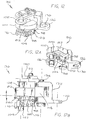
- the guide 52 is preferably disposed in contiguous relationship to a pinch roller 100 so that the tension of the tape is precisely regulated when the tape becomes disposed on the periphery of the pinch roller.
- the guide 52 ( Figures 12-13) is coupled as by bolts 98 to a pinch roller assembly generally indicated at 96.
- the pinch roller assembly 96 includes the pinch roller 100.
- the guide 52 is adjustably positioned relative to the pinch roller 100 as by a pair of eccentrics 104 and 106 ( Figures 12, 12A, 12B and 13).
- the eccentric 104 may be operative to move the guide 52 vertically in accordance with the rotation of the eccentric.
- the eccentric 106 may be operative to move the guide 52 vertically so as to adjust the tilt of the guide relative to the pinch roller 100.
- eccentrics such as the eccentrics 104 and 106 are well known to persons of ordinary skill in the art. Furthermore, the construction of the eccentric 106 may correspond to the construction of the eccentric shown in Figures 24-26. Although the construction of the eccentrics 104 and 106 is considered to be well known in the art, the use of such eccentrics in a pinch roller assembly is not believed to be known in the art.
- the pinch roller 100 may be molded on a shaft 108 and may be constructed from a suitable material such as a polyurethane.
- a suitable material such as a polyurethane.
- Polyurethane is a desirable material because it has very good wear characteristics and because it takes only a minimal permanent set from continued pressure from a capstan abutting the pinch roller in the operative relationship of the pinch roller and the capstan.
- Polyurethane is also desirable from the standpoint of its ability to adhere to the shaft 108 and also from the standpoint of having a low hysteresis in resisting the effects of heat.
- a suitable polyurethane for use as the pinch roller 100 may be obtained from Harkness in Bristol, Connecticut. This polyurethane may have a hardness of 60 Shorr on the A scale.
- the shaft 108 is supported in a bearing 110 ( Figure 13 and 14) on a support plate 112 which is supported on a knuckle support 114 ( Figure 13).
- the support plate 112 is precisely positioned on the knuckle support 114 as by pins 116 and is then secured to the frame as by threaded bolts 118.
- a bearing plate 120 is secured to the top of the support plate 112 as by a threaded bolt 122.
- the bearing plate 120 is provided with lugs 124 ( Figure 14) which extend downwardly and engage the bearing 110 to create a force having axial and radial components on the bearing, the radial component of the force being directed inwardly toward the shaft 108.
- the polyurethane pinch roller 100 is also preferably ground on centers to obtain a run-out of less than two ten-thousandths of an inch (0.0002").
- the attention devoted to the pinch roller 100 and the supporting structure as discussed above assures that the pinch roller 100 will not wobble as it rotates. Wobbling of the pinch roller 100 is undesirable because it creates inaccuracies in the transfer of magnetic information from the master tape 10 to the thermomagnetic layer 14 on the slave tape 12.
- the pinch roller 100 is rotated by the capstan as a result of tension between the master tape 10 and the slave tape 12.
- the pinch roller assembly 96 includes a base member 126 ( Figures 12-13 and 15) extending from the bottom of the frame 114.
- the member 126 has a hole 130 for receiving a positioning knuckle 132 ( Figure 15) to provide for a rotation of the knuckle support 114 on the knuckle 132.
- the base member 126 forms a part of a frame 133.
- the knuckle support 114 is pivotably secured to the frame 133 as by a pivot pin 134 ( Figures 12B and 13).
- An adjustable screw 135 (Figure 23) is disposed on a post 137 to adjust the position of the knuckle 132 ( Figure 15).
- a lug 136 extends from the bottom of the knuckle support 114 and cooperates with a recess 138 (Figure 16) in a positioning member 139 of a capstan assembly generally indicated at 140 to define a detent arrangement with the recess for locking the pinch roller assembly 96 to the positioning member 139.
- a bearing 142 ( Figure 15) on the end of the pinch roller shaft 108 is disposed in a slot 144 in a support plate 145 to facilitate the movement of the pinch roller assembly 96 into locking relationship with the capstan assembly 140.
- the pinch roller 100 and the guide 52 may be moved manually between the withdrawn position and the extended position or they may be moved by an actuator 157 ( Figure 1).
- the actuator 157, the vacuum source 59a, the source 60a of pressurized air, the drive motor 123 and the take-up motors 20 and 26 may be operated under the control of a controller 159 ( Figure 1).
- a guide generally indicated at 151 ( Figure 1) and having a construction corresponding to that of the guide 52 is associated with the slave tape 12 in a manner similar to the association between the guide 52 and the master tape 10.
- the guide 151 may have a construction corresponding to that of the guide 51.
- peripheral surfaces 161 and 162 on the guide 151 preferably have less orifices 163 ( Figure 7) than the number of orifices 61 and 62 ( Figures 4 and 6) in the peripheral surfaces 59 and 60 of the guide 52 respectively receiving the vacuum and the air under pressure. This provides for a lower braking action at the peripheral surface 161 of the guide 151 than the braking action provided at the peripheral surface 59 of the guide 52.
- the braking action at the peripheral surface 161 of the guide 151 may be equal to, or greater than the braking action at the peripheral surface 59 of the guide 52.
- the guide 151 is constructed to receive a vacuum from the source 59 in a manner similar to the guide 52. Although the guides 52 and 151 are shown as receiving a vacuum from the source 59a, it may be preferable to use separate sources for the guides 52 and 151 to enhance the tension controls provided by the guides.
- the braking action provided at the peripheral surface 161 is less than the braking action provided at the peripheral surface 59 of the guide 52.
- the slave tape 10 is lengthened as the slave tape 12 is heated to a temperature above the Curie temperature just before the slave tape 12 reaches the capstan. Since the slave tape 12 is lengthened by this heat, it does not have to be tensioned as much at the guide 151 as the tensioning of the master tape 10 by the guide 52 in order to obtain a transfer of the information on the master tape 10 to the slave tape 12 in what constitutes a mirror image after the slave tape has cooled to ambient temperatures.
- the guide 151 is disposed so that the thermomagnetic layer 14 on the slave tape 12 faces outwardly from the external surface of the guide as the slave tape moves along this external surface. As with the relationship between the guide 52 and the pinch roller 100, the guide 151 is positioned close to a capstan 160 in the capstan assembly 140. Although the guide 151 is not adjustably positioned horizontally or vertically in a manner similar to that provided by the eccentrics 104 and 106 ( Figures 12 and 13) for the guide 52, such adjustments may be provided without departing from the scope of the invention.
- the capstan 160 and a shaft 161 ( Figures 17, 18, 20, and 21) extending from the capstan are preferably formed from a single composite piece of material.
- the capstan is built with chrome plated brass brazed to a stainless steel shaft.
- the brass is desirable because it is non magnetic and does not corrode.
- Chrome is desirable because it is hard and can be polished to a fine finish.
- the capstan 160 and the shaft 161 are preferably constructed so that they have a minimal run-out.
- the shaft 162 and the capstan 160 are preferably provided with an eccentricity of less than one ten thousandth of an inch (0.0001").
- the shaft 161 and the capstan 160 are positioned relative to a support plate 167 in a manner similar to that provided for the shaft 108 by the pins 116 and the bolts 118.
- the capstan 160 may be supported by a bearing arrangement (see Figure 14) similar to that provided for the pinch roller 100.
- This arrangement includes bearings 162 and lugs 163 ( Figure 15-18) extending from a plate 164 to fixedly position the capstan 160 in the axial direction and inwardly in the radial direction.
- the capstan assembly 140 is provided with a frame 165 ( Figures 15 and 21) having a slot 166 in its base for adjustable positioning on a table (not shown) on which the capstan assembly rests. When the capstan assembly 140 has been adjusted to the desired position, the capstan assembly is fixedly positioned on the table by tightening screws 168 extending through the slot 166 to the table.
- the capstan assembly 140 is adjustably disposed in the frame 165 relative to the fixedly positioned member 139 ( Figures 16 and 20) which defines at one end the recess 138 for providing the detent relationship with the lug 136 in the pinch roller assembly 96.
- a heater generally indicated at 172 ( Figures 22-23 and 27-28) is disposed between the guide 151 and the capstan 160 to receive the slave tape 12 with the thermomagnetic layer 14 of the slave tape facing the heater.
- the heater is preferably disposed in contiguous relationship to the guide 151 and the capstan 160.
- the heater 172 is preferably constructed to heat only the thermomagnetic layer 14 of the slave tape 12 to a temperature above the Curie temperature. If the supporting tape were heated to a temperature above the Curie temperature, the thermomagnetic layer 14 would tend to shrink relative to the supporting tape. This would tend to cause the tape to become excessively cupped and would prevent the image on the master tape 10 from becoming transferred accurately to the slave tape 12.
- the heater 172 is provided with a relatively short length to prevent the slave tape 12 from becoming blistered by an excessively long time of contact with the heater.
- this contact between the heater 172 and the slave tape should preferably not exceed five milliseconds (0.005 sec).
- the heater 172 is disposed as close as possible to the capstan 160.
- the thermomagnetic layer 14 on the slave tape 12 becomes heated by the heater 172 to a temperature above the Curie temperature.
- the thermomagnetic layer 14 cools somewhat. Therefore, the heater 172 heats the thermomagnetic layer 14 to a temperature sufficiently above the Curie temperature such that the thermomagnetic layer 14 does not cool below the Curie temperature until after the thermomagnetic layer 14 reaches the capstan and contacts the magnetizable layer 11 of the master tape. This causes the magnetic information on the master tape 10 to be transferred accurately to the thermomagnetic layer 14 on the slave tape 12 without having to use any magnetic heads to obtain such a transfer.
- thermomagnetic layer 14 of the slave tape since the temperature of the magnetizable layer 11 of the master tape 10, after contacting the thermomagnetic layer 14 of the slave tape 12, can rise only to the average of the temperatures of the magnetizable layer 11 and the thermomagnetic layer 14 before the contact, the characteristics of the master tape 10 are not affected even if the magnetizable layer 11 is a thermomagnetic layer of the same type as that of thermomagnetic layer 14.
- the heater 172 is disposed in a particular relationship to the guide 151 and the capstan 160.
- the thermomagnetic layer 14 on the slave tape 12 faces away from the external surfaces of the guide 151 and the capstan 160. In facing away from the external surface of the capstan 160, the thermomagnetic layer 14 directly abuts the magnetizable layer 11 on the master tape 10 (see Figure 38). In this way, the transfer of the magnetic information on the master tape 10 to the thermomagnetic layer 14 on the slave tape 12 is facilitated.
- the thermomagnetic layer 14 directly faces the external surface of the heater 172. In this way, heat can be transferred directly to the thermomagnetic layer 14 without having to pass through the backing member supporting the thermomagnetic layer. This facilitates the heating of the thermomagnetic layer 14 to a temperature above the Curie temperature without heating the remainder of the slave tape 12 to such a high temperature.
- the heater 172 is relative short and thin. In this way, the thermomagnetic layer 14 can be heated to a temperature above the Curie temperature without significantly affecting the temperature of the backing member supporting the thermomagnetic layer. Furthermore, by making the heater 172 short and thin, the heater can be disposed close to the capstan 160. This facilitates the ability of the thermomagnetic layer 14 to operate at a temperature close to the Curie temperature when the information on the master tape 12 is being transferred to the thermomagnetic layer.
- the heat from the heater can be transferred to the thermomagnetic layer 14 in a relatively short period of time such as approximately two millisecond (2ms) when the slave tape is moving at a speed of approximately one hundred and fifty inches per second (150 i.p.s.). This is desirable in insuring that only the thermomagnetic layer 14 (and not the supporting tape 12) is heated to a temperature above the Curie temperature.
- the surface of the heater disposed near the capstan 160 can be made flat rather than concave as in the prior art.
- a flat surface has engineering advantages and is significantly simpler to manufacture than a concave surface as in the prior art.
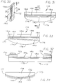
- the heater 172 includes a support member 174 ( Figures 31 and 33).
- the support member 174 is made from an insulating member such as a ceramic.
- Aluminum nitride is a desirable ceramic for certain important reasons. One reason is that it has a low coefficient of thermal expansion. Another reason is that it has a high thermal conductivity. In this way, the support member 174 is able to transfer heat quickly and efficiently to the thermomagnetic layer 14 on the slave tape 10 without changing its physical dimensions appreciably with increases in temperature and without a large thermal gradient.
- Aluminum nitride is also advantageous because it is relatively stable.
- thermomagnetic layer 14 of the slave tape 12 can be polished to a great smoothness so as to maximize the surface area of contact and thus the heat transfer efficiency.
- This external surface is indicated at 176 in Figures 31 and 32.
- the external surface 176 of the support member 174 may define a segment of a cylinder. This cylinder may have a radius of approximately one half of an inch (0.5"). It is desirable that the external surface 176 define a segment of a cylinder in order to assure that pockets of air will not be formed between the external periphery and the slave tape 12 as the slave tape moves along the internal periphery. As will be appreciated, the slave tape 12 moves in the direction of the curvature in the external surface of the support member 174.
- the maximum thickness of the support member 174 may have a dimension of thirty five thousandths of an inch (0.035").
- the external surface 176 of the insulating support member 174 may be rounded at its input end in the direction of movement of the slave tape 12 to provide a smaller radius than the radius at intermediate positions on the member. This assures that the slave tape 12 will not form a gap with the external surface 176 as it initially engages the external surface 176 of the member 174 at the input end of the member. The formation of such a gap is undesirable since it creates air pockets which allow the heater to get excessively hot. The air pockets also prevent the thermomagnetic layer 14 on the slave tape from being heated uniformly as the slave tape moves on the external surface 176.
- the external surface 176 of the member 174 is rounded as at 177 at the output end with a smaller radius than at intermediate positions on this surface. This also prevents air pockets from being produced between the tape 12 and the external surface 176 of the member 174 at the output end of this surface as the slave tape 12 leaves the member.
- the support member 174 has an external surface 178 ( Figure 31) opposite the surface 176.
- the surface 178 is preferably flat.
- the support member 174 when formed from aluminum nitride, may be heated to an elevated temperature such as approximately 950°C in air for a suitable period of time such as approximately two (2) hours. This causes a coating of aluminum oxide to be produced on the external surfaces of the support member 174. This coating of aluminum oxide appears to be desirable in retaining the coatings of materials subsequently deposited on the surfaces of the support member 174.
- a layer 180 ( Figures 31 and 32) of titanium is then deposited on this surface in a suitable thickness such as approximately one thousand Angstrom (1000 ⁇ ). Titanium has good heat conductivity and a low coefficient of thermal expansion. Then a layer 182 of platinum having a thickness such as approximately four thousand Angstrom (4000 ⁇ ) is deposited on the titanium.
- the titanium layer 180 is desirable between the surface 178 of the support member 174 and the platinum layer 182 because titanium has an affinity for aluminum nitride, aluminum oxide and platinum.
- the platinum layer 182 is then annealed at a suitable temperature such as approximately 750°C for a suitable period of time such as approximately fifteen (15) minutes to soften the platinum.
- the platinum layer 182 is then cooled at a suitable rate such as approximately three centigrade degrees (3°C) per minute to room temperature. This annealing of the platinum layer 182 prevents the platinum from cracking when heat and stress are imposed upon the heater 172. It also avoids any problems in the platinum when one side of the heater 172 is at a different temperature than the other side of the heater.
- a layer of gold having a suitable thickness such as 200 micro inches (0.0002 inch) is then deposited as by plating on the platinum.
- the gold in the laterally middle portion of the layer is then removed to define two (2) terminals 190 and 192 ( Figure 32).
- the layers 190 and 192 of plated gold define the terminals for receiving an electrical voltage.
- This voltage is introduced to the gold layer 190 and 192 by straps 193 ( Figure 23) made from a suitable material such as gold-plated copper.
- This voltage produces a flow of current through the platinum layer 182 for heating the platinum layer.
- the platinum layer has a greater thickness on the input side (in the direction of movement of the slave tape 10) of the heater than on the output side of the heater, as indicated on an exaggerated basis at 194 in Figure 33. In this way, the platinum 194 layer develops more heat on the input side of the heater than on the output side of the heater. This is desirable in insuring that the temperature in the thermomagnetic layer 14 of the slave tape 12 is brought quickly above
- the input side of the platinum layer 182 may provide a greater amount of power than the output side of the platinum even with a uniform thickness of the platinum layer. This results from the cooling of the platinum layer by the slave tape 12 as the slave tape contacts the heater. This causes the resistance of the platinum layer at the input side to be lower than the resistance of the platinum layer at the output side because the temperature coefficient of resistivity of platinum is positive. Such differences in resistance value cause the power generated at the input side of the platinum layer to be greater than the power generated at the output side of the platinum layer.
- the distance between the gold terminals 190 and 192 is preferably greater by a particular distance than the lateral width of the slave tape 12. In this way, the thermomagnetic layer 14 on the slave tape 12 is heated substantially uniformly across the lateral width of the slave tape.
- the platinum is able, in the distance between the inner ends of the terminals and the lateral peripheries of the slave tape, to heat the lateral peripheries of the thermomagnetic layer 14 on the slave tape 12 by an optimal amount. This causes the lateral peripheries of the thermomagnetic layer 14 on the slave tape 12 to be maintained at substantially the same temperature as the remainder of the thermomagnetic layer.
- thermomagnetic layer 14 on the slave tape 12 may tend to become overheated relative to the remainder of the thermomagnetic layer. If this distance is too small, the lateral peripheries of the thermomagnetic layer 14 on the slave tape 12 may tend to become underheated relative to the remainder of the thermomagnetic layer.
- the external surface 176 of the support member 174 may be initially coated with a layer 195 ( Figure 34) of titanium having a suitable thickness such as approximately five hundred Angstrom (500 ⁇ ).
- a layer of an electrically conductive material such as gold 196 having a suitable thickness such as approximately eight thousand Angstrom (8000 ⁇ ) may then be deposited as by sputtering on the titanium layer.
- a layer of gold 198 having a suitable thickness such as approximately one mil (1m) may thereafter be deposited as by plating on the gold layer 196.
- the layers 194, 196 and 198 are connected to electrical ground and are effective in dissipating electrostatic charges as such electrostatic charges are formed by movement of the slave tape 10 on the external surface 176 of the member 174.
- the heater 172 is included in a heater assembly generally indicated at 200 ( Figures 22 and 23).
- the heater assembly 200 includes a pair of holder assemblies generally indicated at 202 ( Figure 22).
- the holder assemblies 202 are disposed at the top and bottom of the heater 172 to hold the heater in a fixed position.
- Each of the holder assemblies 202 includes a pair of positioning members 204 and 206 ( Figure 27) which are clamped to each other as by threaded bolts 208 ( Figure 27).
- the positioning members 204 and 206 define an internal socket 193 (Figure 27) for receiving the heater 172.
- the socket 193 is slightly oversized relative to the heater 172 to provide for any expansion of the heater with heat.
- Spacers 205 ( Figures 22 and 23) made from a material providing a low heat transfer are disposed adjacent the positioning members 204 and 206 to limit the transfer of heat from the positioning members.
- a pair of springs 212 are disposed between the positioning members 204 and 206 at the opposite ends of the heater 172 and are disposed on the heater 172 to support the heater in a fixed position within the socket 193.
- the springs 212 may be made from a suitable material such as Inconel 718. Inconel 718 is desirable because it has good properties at high temperatures and because it does not take a permanent set when heated.
- the springs 212 are disposed in the internal socket 193 so as to be expansible with increases in temperature.
- the springs 212 may initially be flat and may be deformed as shown in Figure 27 when they are disposed on the heater 172.
- the springs 212 may be provided with an extended slot 213 to provide for expansion relative to the heater 172 and the positioning members 204 and 206.
- the heater assembly 202 also includes a pair of bridge members 214 ( Figure 22) which are attached to the heater assembly 200 as at 216 to position the heater 172 in facing relationship with the thermomagnetic layer 14 on the slave tape 12.
- a shaft 216 ( Figure 24) extends through the bridge members 214 and a support plate 219 to provide for a pivotal movement of the heater 172 to a position abutting the thermomagnetic layer 14 on the slave tape 12 or to a position displaced from the slave tape.
- the heater 172 becomes displaced from the slave tape 12 as by a spring 215 (Figure 22) which is attached at one end to the heater assembly 200 and at the other end to a fixed post 223.
- a leaf spring 221 ( Figures 17 and 18) acts to move the heater assembly toward the capstan 160 as the pinch roller extends.
- an eccentric 218 is disposed within the support plate 219. As the eccentric 218 is turned, the shaft 216 is moved in a slot 220 ( Figure 26) so as to tilt the heater 172 horizontally. A positioning pin 222 ( Figures 24 and 25) is threaded in a hole 224 in the support plate 219 to lock the eccentric 218 after the eccentric has been turned to the desired position. An insert 226 ( Figure 26) is disposed on the shaft 216 at a position below the eccentric 218. A Belleville spring 228 ( Figure 24) is disposed on the shaft 216 between the insert 226 and a spacer 230 ( Figures 23 and 24) to hold the insert 226 against the eccentric 218 for maintaining the position of the heater assembly.
- Electrical insulators 229 and 231 electrically isolate the upper and lower bridge members 214.
- Electrical terminals 230 ( Figures 23 and 24) are provided on an insulating block 234 disposed between the bridge members 214 at the end of the bridge members opposite the heater 172. The terminals 230 hold the ends of the straps 193 opposite the heater 172.
- Electrical leads 236 extend from the terminals 230 to a voltage source (not shown) for producing a current through the platinum layer 182 ( Figures 31 and 32) or the platinum layer 194 ( Figure 33) to heat the heater.
- the heater 172 is locked in position between two opposite pins when it is disposed to receive the slave tape 12 moving from the guide 151 to the capstan 160.
- One of the pins is disposed on the pinch roller assembly 96 at a position below the guide 151 and is indicated at 240 in Figures 12A and 36.
- the other pin is indicated at 242 in Figures 21, 35 and 36 and is adjustably threaded in a fixed support member 244 in Figures 35 and 36.
- the pin 242 is fixedly retained in the support member 244 as by a nut 246.
- the pins 240 and 242 respectively bear against the opposite surfaces of the lower holder assembly 202.
- the heater 172 When the heater 172 is positioned between the pins 240 and 242, it still has a slight adjustability such as in the order of a few mils. This provides for a fixed and precise positioning of the slave tape 12 on the heater 172 while still providing for a slight adjustment in this precise positioning.
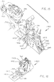
- the pinch roller assembly 96 In order to position the master tape 10 properly on the pinch roller 100 and the slave tape properly on the capstan 160, the pinch roller assembly 96 is moved to a position where the pinch roller is displaced from the capstan 160.
- the guide 52 is also movable with the pinch roller 100 to the position displaced from the capstan 160. With the pinch roller 100 and the guide 52 in the displaced positions, the slave tape 12 can be disposed on the capstan 160.
- the positioning of the slave tape 12 on the capstan 160 is facilitated by the pivotal movement of the heater assembly 200 away from the capstan on the shaft 216 ( Figure 24) as a fulcrum.
- the movement of the heater assembly 200 away from the capstan is provided by the spring 215 in Figure 22.
- the heater assembly 200 can be released. The heater 172 will then return to the position where it abuts the thermomagnetic layer 14 on the slave tape 12. This is provided by the spring 221 ( Figure 17).
- the heater 172 and the capstan 160 When the slave tape 10 has been disposed on the guide 151, the heater 172 and the capstan 160, the bevelled surface and the ledge of the guide 151 corresponding to the bevelled surface 50 ( Figure 9) and the ledge 53 on the guide 52 position the slave tape so that the slave tape moves to a particular position on the capstan 160. If the slave tape 12 does not move to the particular position on the capstan 160, the position of the guide 151 can be adjusted vertically in accordance with adjustments in an eccentric on the guide 151 corresponding to the eccentric 104 ( Figures 12 and 13).
- the position of the guide 151 can also be adjusted vertically, as by a tilting motion, by adjusting an eccentric in the guide 151 corresponding to the eccentric 106 ( Figures 12, 12A, 12B and 13) in the guide 52.
- eccentrics corresponding to the eccentrics 104 and 106 on the guide 52 were not provided on the guide 151.
- it will be appreciated that such eccentrics can be provided on the guide 151 without departing from the scope of the invention.
- the heater 172 can be tilted by adjusting the position of the eccentric 218 ( Figures 24-25) in the heater assembly 200. Since the heater 172 is disposed relatively close to the capstan 160, the adjustment provided by the eccentric 218 can be considered to provide a fine control over the positioning of the slave tape 12 on the capstan. In this way, the movement of the slave tape 12 to the capstan 160 can be controlled so that the slave tape has a precise position on the capstan. This is important in insuring that a precise transfer of information is provided from the master tape 10 to the thermomagnetic layer 14 on the slave tape 12 at the abutting positions of the pinch roller 100 and the capstan 160.
- the master tape 10 is disposed on the guide 52 and the pinch roller 100 while the guide and the pinch roller are displaced from the capstan 160.
- the guide 52 and the pinch roller 100 are then moved to a position where the pinch roller abuts the capstan.
- the pinch roller 100 becomes locked to the capstan 160 by the locking arrangement between the lug 136 ( Figures 12, 12A and 12B) on the pinch roller assembly and the recess 138 ( Figure 16) in the capstan assembly 140.
- the heater 172 When the pinch roller 100 becomes locked to the capstan 160, the heater 172 also becomes locked into position (except for a slight play of a few thousands of an inch) by the pin 240 ( Figures 12A and 36) on the pinch roller assembly 96 and by the adjustably positioned pin 242 ( Figures 35 and 36).
- the master tape 10 is precisely positioned on the pinch roller 100 by the inclined surface 50 ( Figure 9) and the ledge 53 on the external surface of the guide 52.
- the inclined surface 50 and the ledge 53 cause the master tape 10 to become positioned on the ledge 53 as the master tape 10 moves along the guide 52.
- the position of the master tape 10 on the pinch roller 96 can be further adjusted by adjusting the eccentrics 104 and 106 ( Figures 12, 12A, 12B and 13).
- the eccentric 104 provides a vertical adjustment in the position of the guide 52 and the eccentric 106 provides a horizontal adjustment in the position of the guide albeit at a position displaced from the eccentric 104.
- the eccentric 104 and the eccentric 106 in combination provide an adjustment of the height and the tilt of the guide 52. In this way, the master tape 10 can be directed to a position on the pinch roller 100 precisely corresponding to the position of the slave tape 12 on the capstan 160.
- the master tape 10 is strained in one direction by the bevel or incline in the surface 50 ( Figure 9) in the guide 52. This strain in one direction is compensated in the other direction by the pin 48 ( Figures 1 and 11).
- the pin 154 compensates for the strain imposed on the slave tape 12 by the bevel in the surface of the guide 151 corresponding to the inclined surface 50 in the guide 52.
- the guide 52 regulates the tension of the master tape 10 at a position contiguous to the pinch roller 100.
- the guide 151 regulates the tension of the slave tape 12 at a position contiguous to the capstan 160.
- These regulations of tape tension provide for a transfer of the video information on the tape 10 to the thermomagnetic layer 14 on the slave tape 12 in a mirror image with greater fidelity, this mirror image being provided after the slave tape has cooled to ambient temperature. This precise transfer is facilitated by the constant characteristics provided for the master tape 10 and for the slave tape 12.
- the constant characteristics provided for the master tape 10 may be different from the constant characteristics provided for the slave tape 12. This results from the fact that the regulated tension on the master tape 10 may be greater than the regulated tension provided on the slave tape 12 because of the expansion of the slave tape 12 by the heat from the heater 172 just before the slave tape reaches the capstan 160.
- the guide 151 performs the same function on the slave tape 12 as the guide 52 performs on the master tape 10.
- the guide 151 for the slave tape 12 can have less orifices 163 on its peripheral surface 161 than the number of apertures 61 ( Figure 4) at the peripheral surface 59 of the guide 52 for the master tape 10. This may be seen from a comparison of Figures 6 and 7.
- the increased braking action provided by the guide 52 relative to that provided by the guide 151 results from the fact that the slave tape 12 is expanded by the heater 172 as it moves over the heater. In effect, the increased braking action of the guide 52 stretches the master tape 10 to conform to the expansion provided on the slave tape 12 by the heater 172.
- the vacuum source 59a can be small and can have a low capacity.
- a diaphragm type of aquarium pump can be used as the vacuum source 59a.
- a "Supra 4" pump distributed by Willinger Brothers of Wrightway Oakland, New Jersey, has been found satisfactory for use as the vacuum source 59a but a number of other pumps can also be used.
- This pump is designed as a pressure pump. It can be easily modified to provide a vacuum source by reversing the inlet and outlet ports and adjusting the diaphragm position.
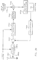
- Figure 39 is a schematic block diagram of a system for regulating the heat produced by the heater 172 and for providing an almost instantaneous heating of the heater on a regulated basis when the apparatus shown in Figures 1-38 initially becomes operative.
- the system shown in Figure 39 includes a potentiometer 280 having an adjustable am 282.
- the voltage on the adjustable arm 282 is introduced to a circuit 284 which multiplies the adjustable voltage by a transfer function such as a time constant to obtain a signal representing the desired amount of power to be introduced to the heater 172.
- the signal from the time constant circuit 284 is introduced to a differencing circuit 286 which also receives a signal input from a wattmeter 288.
- the output from the differencing circuit 286 is introduced to an integrator 290.
- the output from the integrator 290 in turn passes to a stage 292 for obtaining a square root of the output from the integrator.
- the output from the square root stage 292 then passes to a multiplier 294 which also receives a signal on a line 296.
- the signal on the line 296 is an alternating signal having a particular waveform such as a sine wave or a square wave.
- a power amplifier 298 receives the output signal from the multiplier 294 and introduces an amplified signal to the heater 172.
- the input current and voltage to the heater are introduced to the wattmeter 288.
- the system shown in Figure 39 constitutes a closed loop servo for regulating the power introduced to the heater 172 in accordance with a desired amount of power represented by the voltage on the adjustable arm 282 of the potentiometer 280. This voltage is varied by the time constant provided by the stage 284. The resultant signal represents the desired power to be introduced to the heater 172.
- the resultant signal from the stage 284 is introduced to the comparator 286 for comparison with the signal from the wattmeter 288.
- the signal from the wattmeter 288 represents at each instant the amount of power generated by the heater 172 at that instant.
- the output from the differencing circuit 286 accordingly represents at each instant any difference between the desired power and the actual power introduced to the heater 172 at that instant.
- the difference signal from the differencing circuit 286 is introduced to the integrator 290 which integrates the difference signal at progressive instants of time.
- the output from the integrator 290 is introduced to the stage 292 which determines at each instant the square root of the output from the integrator 290.
- the output from the stage 292 accordingly represents the power introduced to the heater 172 at that instant.
- the square root output from the stage 292 is in the form of a variable direct voltage.
- This signal is introduced to the multiplier 294 for multiplication with an alternating signal, such as a sine wave signal or a square wave signal, on the line 296.
- the resultant alternating signal is amplified by the amplifier 298 and the amplified signal is introduced to the heater 172.
- the heat produced in the heater 172 at each instant is regulated in accordance with a desired amount of heat as represented by the voltage on the adjustable arm 282 of the potentiometer 280.
- the square root function 292 assures that the power into the heater is a linear function of the position of the potentiometer arm 282. Without the square root function 292, relatively small changes in the position of the potentiometer arm 282 at typical operating powers will cause large changes in the heater power.
- the potentiometer 280 can be replaced by other command means such as a digital-to-analog converter connected to a microprocessor.
- the system shown in Figure 39 and discussed above provides this regulation on an instantaneous basis. Far example, this regulation is provided in less than a second after the slave tape 12 starts to move.
- the time constant stage 284 and the integrator 290 may be caged while the system shown in Figures 1-38 is not in use. When the time constant stage 284 and the integrator 290 are caged, a low amount of power is introduced to these stages to prepare the system shown in Figure 39 for instantaneous operation when the transfer of information from the master tape 10 to the slave tape 12 is initiated. When the transfer of information from the master tape 10 to the slave tape 12 is initiated, the time constant stage 284 and the integrator 290 are uncaged.
- the system described above has a number of important advantages. It provides a precise transfer of an image on a mirror basis from the master tape 10 to the slave tape 12 after the slave tape has cooled to ambient temperatures. It provides this precise transfer in a minimal period of time. For example, a two (2) hour tape of a movie can be transferred from the master tape 10 to the slave tape 12 in a period of approximately thirty (30) seconds.
- the system is also advantageous in that the master tape 10 can be disposed easily on the pinch roller 100 and the guide 52 associated with the pinch roller and the slave tape can be disposed easily on the capstan 160, the associated guide 151 and the heater 172. This is important when images are being transferred from the master tape 10 to the slave tape 12 on a commercial basis where time is important.
- the system is further advantageous in that the information on the master tape 10 can be transferred to the slave tape 12 without having to use any reading or recording heads.
- the system of this invention also has other important advantages.
- the system of this invention heats essentially only the thermomagnetic layer to a temperature above the Curie temperature. This is important in conserving power and in preserving the characteristics of the slave tape 12 for subsequent use and in providing an accurate transfer of information from the master tape 10 to the slave tape 12.
- the system includes members for maintaining the tension on each of the master and slave tapes substantially constant. This enhances the accuracy in which the information on the master tape 10 is transferred to the slave tape 12.
- the system of this invention maintains the tensions on the tapes substantially constant and damps any variations in the tape tensions. The system accomplishes this by regulating the tension of the master tape 10 at a position contiguous to the pinch roller 100 and by regulating the tension of the slave tape 10 at a position contiguous to the heater 172.
- the guide 151 may be constructed and may be adjustable in the same manner as the guide member 52 to position the slave tape 12 precisely at a particular position on the capstan 160 corresponding to the particular position on the pinch roller 100. If there is any deviation between the particular positions on the pinch roller 100 and the capstan 160, the position of the slave tape 12 on the capstan 160 can be fine tuned by adjusting the position of the heater 172 so that the position of the master tape 10 on the pinch roller 100 and the position of the slave tape 12 on the capstan 160 coincide.
- the construction of the heater 172 and the disposition of the slave tape 12 on the heater are also advantageous.
- the slave tape 12 is disposed relative to the heater 72 so that the thermomagnetic layer 14 on the slave tape 12 abuts the surface of the heater.
- the external surface of the heater 172 is shaped to prevent any air bubbles from lifting the slave tape 12 from the heater.
- the heater 172 is also formed from materials which assure an optimal operation of the heater.
- the heater 172 is also pivotable to a position displaced from the path of the slave tape to facilitate the disposition of the slave tape on the heater and the capstan 160 and disposition of the master tape 10 on the pinch roller 100.
- the invention also provides other advantages of some importance. It includes features for precisely regulating the tension of the master tape 10 just before the movement of the master tape to the surface of the pinch roller 100. It also includes similar features for precisely regulating the tension of the slave tape 12 just before the movement of the slave tape to the surface of the heater 172, which is disposed in contiguous relationship to the capstan 160.
- the system of the invention provides these regulations of tape tension in a way to compensate for the stretching of the slave tape 12 by the heat from the heater 172.
- the master tape 10 can be manufactured with certain specific constant characteristics (including the product of Youngs modulus, thickness and width) so that the mechanism regulating the tension of the master tape 10 never has to be adjusted even when master tapes manufactured at different times in different batches are used.
- the slave tape 12 can be manufactured with certain specific constant characteristics (including the product of Youngs modulus, thickness and width) so that the mechanism regulating the tension of the slave tape 12 never has to be adjusted even when slave tapes manufactured at different times in different batches are used.
- the product of the Youngs modulus, thickness and width for the characteristics of the master tape 10 can have a different value than the product of the Youngs modulus, thickness and width for the characteristics of the slave tape 10 to compensate for the stretching produced in the slave tape by the heater 172.
- the guide 52 has been described as being in contiguous relationship to the pinch roller 100. It will be appreciated, however, that the guide 52 may be disposed at any distance from the pinch roller 100 without departing from the scope of the invention and that the guide at these variable positions will still regulate the tension of the master tape 10 at the pinch roller 100 as described previously in this specification. Similarly, the guide 151 may be varied from a position contiguous to the heater 172 without departing from the scope of the invention.
- the guide 52 may be used with any stretchable medium to regulate the tension of such medium and that the master tape 10 is one form of such a medium.
- the guide 52 may be used to regulate the tension of belts and pulleys.
- such media may provide other transducing actions than the transfer of magnetic information between the master tape 10 and the slave tape 12.
- the slave tape 12 constitutes only one form of stretchable medium which may be used in this invention, and the tension of such medium may be regulated as described above without departing from the scope of the invention.
- stretching of a tape is a function of the tape width, the tape thickness and the Youngs modulus of the tape. This can be used to regulate the force preset in the spring 66 in Figure 5.
- the system shown in the drawings and described above runs the tape such as the master tape 10 at a tension T1 from the beginning of the tape to the end of the tape.
- the angle of rotation of the pinch roller 100 to provide such a tape movement is measured by a meter 300 in Figure 43.
- the tape such as the master tape 10 is again run from beginning to end with the tape at a tension T2.
- the tension T can be preset by adjusting the constraint of the spring 66 in Figure 5.
- the constraint of the spring 66 is adjusted by adjusting the screw 67 in Figure 5.
- a microprocessor 302 can instruct an adjusting mechanism 304 to adjust the screw 67 in Figure 5 to obtain the tension T1, and then to obtain the tension T2, in the tape 10.
- the microprocessor can then determine the change in the tension, ⁇ T, from the values set for the tension values T1 and T2.
- the microprocessor 302 can also use the measurements obtained from the meter 300 to determine the value of ( ⁇ 2- ⁇ 1)/ ⁇ 2(T2-T1), this value being representative of the product of the width, thickness and Youngs modulus of the master tape. From this determination, the microprocessor 302 can then calculate the tension to be applied to the master tape 10 to produce a desired strain in the tape.
- the microprocessor 302 can then instruct the adjusting mechanism 304 to produce the proper constraint in the spring 66 in Figure 5 for the production of the desired strain in the master tape 10.
Abstract
Description
- This invention relates to apparatus for, and methods of, transferring visual and audio information on a master tape to a slave tape. More particularly, this invention relates to apparatus for, and methods of, transferring visual and audio information in magnetic form on a master tape to a thermomagnetic layer on a slave tape. The invention also relates to a master or slave tape with properties individual to the apparatus and methods of this invention.
- Visual and audio information is often stored on a tape for playback at a subsequent time. For example, visual and audio information relating to popular motion pictures is stored on tapes. These tapes are rented or sold at neighborhood stores. A popular movie such as "Batman" or a movie winning an Academy Award has millions of taped copies distributed to satisfy the demands of purchasers and renters. Substantially all of these taped copies have to be made available at a pre-selected release date in order to satisfy the pent-up demand of viewers for such taped copies. Although the demand for movie rentals and sales is great, the demand still seems to be increasing significantly from year to year.
- Visual and audio information on tapes is not only provided in the form of movies for entertainment. It is also provided in large volume for business purposes. For example, large corporations deliver messages in the form of tapes to their sales personnel to acquaint such sales personnel with the construction, operation and advantages of new products. Since large corporations employ large numbers of sales copies, many copies of such messages have to be prepared for distribution to their sales personnel.
- The visual and audio information on most tapes is in magnetic form. One reason is that information in magnetic form can be relatively easily and inexpensively reproduced. For example, most reproducing apparatus in the home use magnetic heads to read the information recorded magnetically on the tapes when the tapes are inserted into such apparatus. Another reason is that tapes with information recorded in magnetic form are less expensive to reproduce than tapes in other forms such as in optical form.
- One type of tape for recording information in magnetic form has a thermomagnetic layer on the tape. The thermomagnetic layer may be formed from a suitable material such as chromium dioxide. The thermomagnetic layer has a Curie temperature at or above which any magnetic information on the tape is destroyed and below which magnetic information can be recorded on the tape. Thermomagnetic tape is advantageous because information can be recorded on the thermomagnetic tape at a temperature at or somewhat above the Curie temperature by pressing a master tape against the thermomagnetic layer on the slave tape at such a temperature. This causes the surface of the thermomagnetic layer to become cooled to a temperature below the Curie temperature by contact with the cool surface of the master tape. As the thermomagnetic layer cools to a temperature below the Curie temperature, the magnetic information on the master tape becomes transferred to the thermomagnetic layer on the slave tape. The information on the master tape thus becomes transferred in mirror form to the thermomagnetic layer on the slave tape without having to use any magnetic heads to write information on the slave tape.
- There is at least one apparatus now in use for transferring information in magnetic form on a master tape to a thermomagnetic layer on a slave tape. Although this apparatus is fast, it is large, cumbersome and expensive, and it requires excessive electrical power. It is accordingly not economical to transfer images from a master tape to a slave tape by using the apparatus.
- With the millions of copies that have to be made of a single movie such as the movie winning an Academy Award, it would be desirable to provide apparatus which is relatively inexpensive and which transfers information from a master tape to a slave tape in a minimal period of time and with low consumption of power. For example, it would be desirable to provide equipment which sells at most for a few thousand dollars and which reproduces a two (2) hour movie in approximately thirty (30) to sixty (60) seconds without any need for using magnetic reproducing heads. Because of the desire, and actually the need, for such apparatus, a considerable effort has been devoted, and a significant amount of money has been expended, to develop apparatus which meets such criteria. In spite of such effort and such money expenditure, no satisfactory apparatus meeting such criteria has been provided to this date.
- Co-pending application Serial No. 733,174 filed by Alfred M. Nelson and Robert P. Adams on July 19, 1991, for a "Tape Duplicating System" provides apparatus which more than meets the criteria specified in the previous paragraph. It is able to record a two (2) hour movie in approximately thirty (30) to sixty (60) seconds such that the duplicated copy has the visual and audio fidelity of the original or master copy. It is compact so that it occupies relatively little space. This is important when a large number of apparatuses are used simultaneously in an enclosure such as a room to make duplicate copies. For example, the apparatus can be used to transfer the information on a master-master tape to a master tape, and subsequently the same apparatus can be used to transfer the information on the master tape to the slave tape, all without using recording heads. The apparatus also consumes low amounts of power.
- In the apparatus disclosed and claimed in co-pending application Serial No. 733,174, a master tape moves between first supply and take-up reels over a pinch roller. A slave tape moves between second supply and take-up reels over a capstan. First and second guides can be respectively constructed and adjustably positioned to regulate the movement of the master and slave tapes to aligned positions on the pinch roller and the capstan. A heater disposed between the capstan and the second guide heats only a thermomagnetic layer on the slave tape to at least the Curie temperature. The heater is adjustable in position to facilitate the movement of the slave tape to the aligned position on the capstan. A brake shoe between the capstan and the second supply reel controls the tape tension and damps any variations in the tension of the slave tape. A second brake shoe between the pinch roller and the first supply reel controls the tape tension and damps any variations in the tension of the master tape.
- The pinch roller is movable to a first position and locked in position relative to the capstan, in which it abuts the capstan to facilitate the transfer of magnetic information from the master tape to the slave tape. In this disposition, the pinch roller locks the heater in a fixed position relative to the capstan. The pinch roller and the associated guide are movable to a second position displaced from the capstan to facilitate the disposition of the master tape on the pinch roller. The heater is pivotable relative to the capstan to facilitate the disposition of the slave tape on the capstan. The capstan, preferably of a unitary construction, receives forces to maintain the capstan rotational axis substantially constant.
- Since the tapes pass over surfaces between the brake shoes and the capstan and the pinch roller, the tensions on the master and slave tapes are not as closely regulated at the position of transfer of the magnetic information from the master tape to the slave tape as might otherwise be desired. Specifically, the tapes pass over alignment guides which have a variable friction with time and physical conditions. This variable friction inhibits a precise regulation of the tape tensions at the abutting positions between the capstan and the pinch roller where the magnetic information is transferred to the slave tape.
- In one embodiment of this invention, a master tape movable in a closed loop including a pinch roller transfers a mirror image to a slave tape movable in a closed loop including a capstan. A thermomagnetic layer on the slave tape has a Curie temperature above which magnetic information is destroyed and below which magnetic information can be recorded on such layer. The thermomagnetic layer is heated above the Curie temperature and is accordingly lengthened by thermal expansion just before the slave tape reaches the capstan.
- A first guide contiguous to the heater regulates the slave tape tension. A downstream portion of a peripheral surface, preferably defining a cylindrical segment, on the guide receives a pressurized fluid for sensing the tape tension in accordance with the tape width, the spacing from the axis of the peripheral surface and the fluid pressure. An upstream portion of the peripheral surface receives a vacuum adjustable to vary the spacing between the slave tape and the downstream portion. This regulates the tape tension.
- The master tape is lengthened by a second guide having the same construction as the first guide to compensate for the lengthening of the slave tape by the heater and the first guide, thereby producing a true mirror image on the slave tape after the slave tape has cooled to the ambient temperature. Each of the master tape and the slave tape has a particular product of the Youngs modulus, tape width and tape thickness to provide a controlled strain on the tape when the tension on the tape is regulated.
- This invention provides apparatus for, and methods of, regulating the tension of a master tape at a position contiguous to a pinch roller and for regulating the tension of a slave tape at a position contiguous to a heater, which is in turn contiguous to a capstan. The apparatus and method of this invention are adapted to be used in the apparatus and method of co-pending application Serial No. 733,174 and to constitute an improvement in the apparatus and method of co-pending application Serial No. 733,174 . The invention also provides a master tape and a slave tape which may be constructed especially for the apparatus and method of this invention to obtain all of the advantages provided by the apparatus and method of this invention.
- In the drawings:
- Figure 1 is a schematic plan view, partly in block form, of one embodiment of apparatus for transferring the information, preferably in magnetic form, on a master tape to a slave tape;
- Figure 2 is an enlarged perspective view of a portion of the apparatus shown in Figure 1 and illustrates this portion of the apparatus in additional detail, this portion including the members adjacent to and including the position where the information on the master tape is transferred to the slave tape;
- Figure 3 is an enlarged perspective view of braking apparatus associated with a supply reel or cassette (also shown in Figure 1) for controlling the unwinding of a tape from the supply reel;
- Figure 4 is an enlarged plan view of a guide means (also shown in Figure 1) for regulating the tension of the tape at a position contiguous to a pinch roller which receives the master tape and provides for a mirror transfer of the image on the master tape to a slave tape;
- Figure 5 is an enlarged sectional view of apparatus associated with the guide means shown in Figure 4 for operating in conjunction with the apparatus shown in Figure 4 for regulating the tension on the master tape at the position contiguous to the pinch roller;
- Figure 6 is an enlarged schematic elevational view of the external surface of the guide means (also shown in Figure 1, 4 and 5) associated with the master tape;
- Figure 7 is an enlarged schematic elevational view of the external surface of the guide means (also shown in Figure 1) associated with the slave tape, the guide means associated with the slave tape being constructed in a manner similar to the construction of the guide means associated with the master tape;
- Figure 8 is an enlarged perspective view of a portion of the apparatus included in Figure 1 and specifically illustrates the construction of a guide pin, the guide means shown in Figures 4 and 6 and a pinch roller and the disposition of these members in the path of movement of the master tape;
- Figure 8A is an enlarged perspective view of the external surface of the guide means shown in Figure 8;
- Figure 9 is an enlarged fragmentary sectional view taken substantially on the line 9-9 of Figure 8 and illustrates in additional detail the construction of the guide means for the master tape at the input end of the guide means in the direction of movement of the master tape;
- Figure 10 is an enlarged fragmentary sectional view taken substantially on the line 10-10 of Figure 8 and illustrates additionally the construction of the guide means;
- Figure 11 is an enlarged fragmentary sectional view taken substantially on the line 11-11 of Figure 8 and illustrates in further detail the construction of the guide pin for the master tape in the direction of movement of the master tape;
- Figure 12 is an enlarged perspective view of the pinch roller and the guide means, as seen from a position above and to one side of such means, for receiving the master tape, the pinch roller being disposed in a position withdrawn from an abutting relationship with a capstan;
- Figure 12A is an enlarged perspective view of the pinch roller and guide means shown in Figure 12 as seen from a position below and to the other side of such means with the pinch roller and the guide means in the withdrawn position;
- Figure 12B is an enlarged elevational view of the pinch roller and the guide means with the pinch roller and the guide means in the extended position;
- Figure 13 is an enlarged, partly exploded, perspective view of the pinch roller and the guide means with the pinch roller and the guide means in the withdrawn position;
- Figure 14 is an enlarged fragmentary sectional view taken substantially on the line 14-14 of Figure 13 and illustrates a bearing assembly associated with the pinch roller for assuring that the pinch roller does not rotate in an off-round relationship;
- Figure 15 is an enlarged exploded perspective view of the pinch roller and the guide means shown in Figures 12-14 and of the capstan assembly, as seen from a position above and to one side of these members, with the pinch roller and the guide means in the extended relationship shown in Figure 18;
- Figure 16 is an enlarged perspective view of the capstan assembly, as seen from a position above and to the other side of the capstan assembly;
- Figure 17 is an enlarged perspective view of the pinch roller and the associated guide means and of the capstan assembly, as seen from a position above and in front of these members, when the pinch roller and the guide means have been extended almost to the position of the pinch roller abutting the capstan;
- Figure 18 is an enlarged perspective view of the pinch roller and the associated guide means and the capstan assembly, as seen from a position above and in front of these members, when the pinch roller and the guide means have been extended to the position of the pinch roller abutting the capstan;
- Figure 19 is an enlarged fragmentary sectional view taken substantially on the line 19-19 of Figure 18 and illustrates the construction of an assembly for providing for the movement of the pinch roller and the associated guide means between the withdrawn and extended positions;
- Figure 20 is an enlarged perspective view of the capstan assembly and associated members, including associated guide means, for guiding the movement of the slave tape to the capstan, the view being provided from a position above and to one side of these members;
- Figure 21 is an enlarged perspective view of the capstan assembly and the associated members, including the associated guide means shown in Figure 20, as seen from a position above and to the other side of these members, and also shows a disposition of the slave tape on these members;
- Figure 22 is an enlarged perspective view of a heater assembly including a heater for heating the thermomagnetic layer on the slave tape to a temperature above the Curie temperature just before the slave tape reaches the capstan, the view being taken from a position above and to one side of the heater assembly;
- Figure 23 is an enlarged perspective view of the heater assembly and the capstan assembly and the associated guide means as seen from a position above and to the other side of the heater assembly and further illustrates the disposition of the slave tape on the guide means, the heater and the capstan;
- Figure 24 is an enlarged fragmentary sectional view taken substantially on the line 24-24 of Figure 22 and illustrates the construction of the pivot assembly for pivoting the heater assembly between a position with the heater receiving the slave tape and a withdrawn position and further illustrates the members for tilting the heater assembly relative to the capstan;
- Figure 25 is an enlarged fragmentary sectional view taken substantially on the line 25-25 of Figure 24 and illustrates in additional detail the construction of the members for tilting the heater assembly relative to the capstan;
- Figure 26 is an enlarged fragmentary view taken substantially on the line 26-26 of Figure 24 and illustrates in further detail the construction of the members for tilting the heater assembly relative to the capstan;
- Figure 27 is an enlarged sectional view taken substantially on the line 27-27 of Figure 22 and illustrates the heater and the construction of members for holding the heater in a fixed position on the heater assembly;
- Figure 28 is a schematic perspective view illustrating the disposition of the slave tape on the heater;
- Figure 29 is an enlarged fragmentary perspective view of the heater and illustrates additional details concerning the construction of the heater;
- Figure 30 is a perspective view of the heater for instantaneously heating the thermomagnetic layer on the slave tape to a temperature above the Curie temperature;
- Figure 31 is an enlarged fragmentary sectional view taken on the line 31-31 of Figure 30 and illustrates the different layers of material which are disposed on an electrically insulating support member to form one embodiment of the heater;
- Figure 32 is an enlarged sectional view taken substantially on the line 32-32 of Figure 31 and illustrates additional details of the embodiment of the heater shown in Figure 31;
- Figure 33 is an enlarged fragmentary sectional view corresponding to the view shown in Figure 31 and illustrates a modification of the heater shown in Figure 31;
- Figure 34 is an enlarged fragmentary sectional view taken substantially on the line 34-34 of Figure 30 and illustrates a modification to the embodiment shown in Figure 31;
- Figure 35 is an enlarged fragmentary plan view of the pinch roller, the capstan, the guide means associated with the capstan, and the heater assembly in the operative positions of these members;
- Figure 36 is an enlarged fragmentary view, partly in section, of the portion of the members shown in Figure 35 within a broken circle designated by the numeral "36" in Figure 35;
- Figure 37 is an enlarged fragmentary sectional view taken substantially on the line 37-37 of Figure 35 and illustrates a portion of the pinch roller and the capstan and the master and slave tapes with the master and slave tapes in abutting relationship to each other and to the pinch roller and the capstan;
- Figure 38 is a fragmentary sectional view, enlarged with respect to Figure 37, of the portion of the members within the broken circle designated by the numeral "38" in Figure 37 and particularly illustrates the abutting relationship of the magnetic layer on the master tape and the thermomagnetic layer on the slave tape;
- Figure 39 is a schematic block diagram of a system for regulating the heat produced by the heater for the thermomagnetic layer on the slave tape and for providing a rapid heating of the heater on a regulated basis when the apparatus shown in the previous Figures initially becomes operative;
- Figure 40 provides a curve illustrating the relationship between tape tension and a parameter such as a sensor voltage for presetting the apparatus shown in Figure 5 to regulate the tension on the guide means shown in Figure 4;
- Figure 41 schematically illustrates the disposition of the master tape on the periphery of the guide means shown in Figure 4 when the tension of the tape has been regulated to a preselected value,
- Figure 42 provides a curve showing the relationship between the flow of air under pressure to the periphery of the guide means shown in Figure 4 and the pressure of the air providing such flow; and
- Figure 43 is a schematic diagram, partly in block form, of apparatus for determining the characteristics of a tape (either master or slave) and for setting the constraint of a spring shown in Figure 5 to provide a particular strain or tension on the master or slave tape during the process of transferring information from the master tape to the slave tape.
- The apparatus of this invention is intended to constitute an improvement of the apparatus disclosed and claimed in co-pending application Serial No. 733,174. Many of the drawings of this application are identical, or substantially identical, to corresponding drawings in co-pending application Serial No. 733,174. Because of this, if there is any deficiency in the drawings or disclosure of this application, the drawings and disclosure of co-pending application Serial No. 733,174 are intended to complete the disclosure of this application.
- In one embodiment of the invention, a master tape 10 (Figure 1) is provided with a mirror image of information such as visual pictures and aural sound to be produced on a
slave tape 12. Preferably the mirror image of the visual and aural information is recorded in magnetic form on themaster tape 10. The mirror image may be recorded in either analog or digital form. The visual and aural information may be provided in a layer 11 (Figure 38) of a magnetizable oxide such as an iron oxide on the surface of the backing member of the master tape. The magnetizable oxide 11 may be formed in a conventional manner on themaster tape 10. - A slave tape 12 (Figures 1 and 38) preferably has a thermomagnetic layer 14 (Figure 38) on the tape. The
thermomagnetic layer 14 may be formed on the backing member of theslave tape 12 from a suitable material such as chromium dioxide in a manner well known in the art. Thethermomagnetic layer 14 preferably has a Curie temperature above which magnetic information in the thermomagnetic layer is destroyed and below which the magnetic information on the master tape can be duplicated in the mirror image on thethermomagnetic layer 14 on the slave tape. Preferably the duplication occurs at a temperature close to, but below, the Curie temperature. When this occurs, the duplication can occur by pressing the master and slave tapes together and can occur without any need to provide magnetic heads for recording the magnetic information from themaster tape 10 on theslave tape 12. It will be appreciated that the magnetic layer 11 on themaster tape 10 may also be formed from a thermomagnetic material. - As will be described, one of the features of this invention is that the tension of the master tape and the tension of the slave tape are respectively regulated at particular values at positions respectively near the positions where the information on the master tape is transferred in a mirror image to the slave tape. Another feature of this invention is that each of the master tape and the slave tape is provided with particular characteristics so that the strain (the elongation in inches per inch) on each slave tape is maintained at a first particular value and the strain on each slave tape is maintained at a second particular value. These strains are chosen so that a precise image is recorded by each master tape in a mirrored form on each slave tape when the slave tape has cooled to an ambient temperature. This provides for an accurate playback of the image on a VCR machine with a high resolution.
- The
master tape 10 can be initially wound on a supply reel orcassette 16 and can then be unwound from the supply reel orcassette 16 and wound on a take-up reel or cassette 18. The unwinding of themaster tape 10 from thecassette 16 by a capstan motor 123 (Figure 1) and the winding of the master tape on the cassette 18 can occur through the operation of a take-up motor 20 (Figure 1). Thecassettes 16 and 18 and the take-upmotor 20 can be constructed in a conventional manner as in a video cassette reproducer found in many homes. Similarly, a supply reel orcassette 22, a take-up reel orcassette 24 and a take-upmotor 26 can be provided for theslave tape 12. - An annular control member 28 (Figures 1 and 3) is disposed in a concentric relationship with the
cassette 16 on ashaft 30. Astrap 32 is wound partially around theannular control member 30 and is attached at one end as at 34 to a mechanical ground. At the other end, thestrap 32 is attached to an intermediate position on arod 36 which is pivotable at one end as at 38. At is other end, therod 36 has apin 40. The construction and arrangement of theannular control member 28, theshaft 30, thestrap 32 and therod 36 are well known in the art of video cassette recording and reproducing equipment. A similar arrangement may also be provided in association with the supply reel orcassette 22. - The
master tape 10 extends from thecassette 16 over a pin 42, thepin 40 on therod 36, apin 44, a post 46 (Figure 1) and a guide pin 48 (Figures 1, 8, and 11) to theperipheral surface 50 of an alignment guide generally indicated at 52. Theperipheral surface 50 of thealignment guide 52 is inclined at a small angle (Figure 9) at its upstream end. This small angle causes the tape to ride down toledge 53, thus accurately aligning the tape to the ledge height. Theguide pin 48 is tilted to provide compensation for the differential strain introduced by theinclined surface 50 of thealignment guide 52. The optimum tilt angle is a function of the wrap angle, the tension of the tape, and the slope of thealignment guide 52. If the tilt is too large, the tape will ride upwardly off the ledge of the alignment guide at the input end. If the tilt is too small, excessive force will be created on the tape edge. This can result in a buckling of the tape at the input end of thealignment guide 52 and wear of theledge 53. - At the downstream end of the
guide 52, the slope of the guide face on thealignment guide 52 transitions to a perpendicular relationship with the pinch roller. This is indicated at 55 in Figure 10. Thus the tape exits the guide in a plane parallel to the pinch roller axis and without differential strain. Theinclined surface 50 and the perpendicular surface 55 are undercut as at 54 (Figures 8A, 9 and 10) to assure that the tape will have a planar disposition along the inclined and perpendicular surfaces. - The
guide 52 may be hollow and may be provided with an internal wall as at 56 at an intermediate position to define a pair ofisolated chambers 57 and 58 (Figure 4). Thechamber 57 is upstream from thechamber 58 in the direction of movement of themaster tape 10. Theguide 52 may be provided with a pair ofperipheral surfaces peripheral surfaces Orifices 61 communicate thechamber 57 with theperipheral surface 59 and orifices 62 communicate thechamber 58 with theperipheral surface 60. A variable vacuum is produced in thechamber 57 and a fluid (e.g. air) under a variable pressure is introduced to thechamber 58. The variable vacuum may be produced by a vacuum source 59a (Figures 1 and 5) and the air under pressure may be obtained from a source 60a (Figures 1 and 5). Areservoir 61 and an orifice 61a may be disposed between the vacuum source 59a and thechamber 57. Similarly, a reservoir 62 and an orifice 62a may be disposed between thesource 61 and thechamber 58. - The variable vacuum in the
chamber 57 and the variable pressure above atmospheric pressure in thechamber 58 are produced by the valving mechanism generally indicated at 63 in Figure 5. Thevalving mechanism 63 includes atube 64 closed at one end (e.g. the upper end) in Figure 5. A constraining member such as a spring 66 is attached at one end to the closed end of thetube 64 and at the other end to arod 65. The spring 66 constrains therod 65 for movement in an upward direction. An arrangement including ascrew 67 and anadjustable nut 68 are provided at the closed end of thetube 64 to adjust the constraint on the spring 66. The upper end of the spring 66 is attached to the bottom end of thescrew 67 to provide for the adjustment in the constraint of the spring when thescrew 67 is turned in thenut 68. - Air under a variable pressure is introduced through a
conduit 68 from the source 60a of pressurized air to afirst chamber 69 which may be isolated from thetube 63. Anextension 65a of therod 65 extends through thechamber 69 and through aresilient diaphragm 70 in sealed relationship to thechamber 69. Thediaphragm 70 is coupled to therod 65 for movement upwardly and downwardly in accordance with the movement of the piston. Thediaphragm 70 defines one end of a second chamber 71 which receives air at atmospheric pressure through aconduit 72. The opposite end of the chamber 71 is defined by aresilient diaphragm 73 which is sealed to thepiston 65 for movement with the piston. - A variable vacuum is introduced from the
vacuum source 59 through a conduit 74 to athird chamber 75 which is isolated from the second chamber 71 by theresilient diaphragm 73. Thevacuum chamber 75 is open at one end (e.g. the bottom end in Figure 5) to define avalve seat 76. A valve rod 77 preferably having a conical configuration defines with the valve seat 76 a valve having a variable leakage to the atmosphere in accordance with the vertical positioning of the valve rod relative to the valve seat. The valve rod 77 constitutes an extension of thepiston 65. - The spring 66 is provided with characteristics to produce a particular tension on the
master tape 10 as the master tape moves along the peripheral surface 60 (Figure 4) of theguide 52. This tension provides a displacement of themaster tape 10 from theperipheral surface 60 of theguide 52. This is indicated by the distance ΔR in Figure 41. The magnitude of this tension determines the radial distance R+ΔR of the displacement of thetape 10 from the axis of theperipheral surface 60 of theguide 52. As the radial distance ΔR between themaster tape 10 and theperipheral surface 60 of theguide 52 increases, an increased amount of the air under pressure is able to escape from thechamber 58 through the orifices 62 and into the atmosphere through the space between themaster tape 10 and theperipheral surface 60 of theguide 52. This causes the pressure of the air passing from thesource 60 of pressurized air through theconduit 68 to the chamber 69 (Figure 5) to decrease. - The decreased pressure of the air in the chamber 69 (Figure 5) causes the force exerted downwardly by the air in the
chamber 69 to decrease. Because of this, the force exerted upwardly by the spring 66 on therod 65 becomes dominant so that the rod is moved upwardly in Figure 5. This causes the opening between the valve rod 77 and thevalve seat 76 to decrease such that an increased vacuum is produced in thechamber 75. This increased vacuum results only from the force of thespring 68 since the force exerted downwardly on therod 65 by thediaphragm 73 is equal and opposite to the force exerted upwardly on the rod 77 by the atmospheric pressure below the rod. This results from the fact that the area of thediaphragm 73 is equal to the area of thevalve seat 76. This increased vacuum is also introduced to thechamber 57 in Figure 4. - The increased vacuum in the chamber 57 (Figure 4) produces an increased force on the
master tape 10 in a direction to position the tape firmly on theperipheral surface 59 of theguide 52 as the tape moves on such peripheral surface. This increased force produces an increased friction between themaster tape 10 and theperipheral surface 59 of theguide 52. Thetape 10 is pulled at a constant speed by acapstan 160 in proximity with a pinch roller 100 (Figure 18) and the increased friction of the tape with respect to the peripheral surface causes an increased tape tension. This increased tension on themaster tape 10 produces a decrease in the spacing between themaster tape 10 and theperipheral surface 60 of theguide 52. The decreased spacing between themaster tape 10 and theperipheral surface 60 of theguide 52 provides for an increase in the pressure of the fluid passing from the source 60a of pressurized air through theconduit 68 to thechamber 69 in Figure 5. - The increased pressure of the fluid in the
chamber 69 results in a downward movement of therod 65 to open the valve defined by the rod 77 and thevalve seat 76. The opening of this valve causes the vacuum introduced to thechamber 57 to decrease, thereby decreasing the frictional force produced on themaster tape 10 on theperipheral surface 59 of theguide 52. In this way, the tension of themaster tape 10 is regulated at a value dependent upon the constraint provided by the setting of the spring 66. - As will be seen from the above discussion, the tape tension sensor may be considered to be produced by an air bearing between the
tape 10 and theperipheral surface 60 of the tape. Since thetape 10 does not touch theperipheral surface 60 of theguide 52, there is no frictional retarding force on thetape 10 as the tape moves along this peripheral surface. The tape tension sensed is accordingly a true representation. The variables affecting the pressure sufficiently only to lift thetape 10 slightly from theperipheral surface 60 may be intuitively, but not vigorously, seen from the following analysis. - The air pressure sufficient in the tape sensor to lift the
tape 10 slightly from theperipheral surface 60 is proportional to the tape tension since the normal force caused by the tape tension must be overcome linearly by the air pressure. The air pressure sufficient to lift thetape 10 is inversely proportional to the area of the tape in contact with the tape tension sensor since an air pressure over an increased area will overcome an increased normal force (and hence tape tension). - If the convex surface receiving the
tape 10 is a section of a cylinder (as is theperipheral surface 60 in Figure 4), the area of thetape 10 in contact with the tape tension sensor is proportional to the radius of the cylindrical segment defined by theperipheral surface 60 of the guide 52 (because the radius of the cylindrical segment is proportional to the circumference of the cylindrical segment and the tape width is constant). Furthermore, the area of thetape 10 is proportional to the width of the tape. - In view of the above,

where - P =
- the air pressure at the
peripheral surface 60; - K =
- a constant;
- T =
- the tension of the
tape 10 at theperipheral surface 60; - W =
- the width of the
tape 10; - R =
- the radius defined by the
tape 10 with respect to the axis of the cylindrical configuration of theperipheral surface 60 - Solving for T in equation (1)

Thus, the tension of thetape 10 is proportional to the product of the width of thetape 10, the radius of the tape with respect to the axis of theperipheral surface 60 of theguide 52 and the air pressure at theperipheral surface 60. As previously described, the air pressure is dependent upon the spacing between thetape 10 and theperipheral surface 60 of theguide 52. - The following is a more vigorous analysis to determine the tension T of the
master tape 10 than that specified above in equations (1) and (2). Assume that the tension sensor has the shape of a cylinder with a radius R and thetape 10 rides over a sector (in radius) of the cylindrical surface defined by the tape sensor. Assume also that there is a chamber within this cylindrical surface and that this chamber (e.g. thechamber 58 in Figure 4) has a pneumatic pressure which is positive with respect to atmospheric pressure. Assume further that there are a multiplicity of orifices (e.g. the orifices 62 in Figure 4) communicating between the chamber (e.g. the chamber 58) and the peripheral surface (e.g. the surface 60) and that all of these orifices are under thetape 10. - On the basis of the assumptions in the previous paragraph, for a particular tape tension T, there is within the chamber (e.g. the chamber 58) a particular pressure P which will lift the tape slightly above the cylindrical surface (e.g. the surface 60). This slight distance can be designated as ΔR as shown schematically in Figure 41. This increase ΔR in the radial distance of the
tape 10 from theperipheral surface 60 of theguide 52 causes an increase ΔL to occur in the length of thetape 10 over the sector φ defined by theperipheral surface 60. Then the energy required to move thetape 10 the distance ΔL against the action of the tape tension T equals the energy required to increase the volume of air by the increment ΔV under thetape 10 at an air pressure P. - The relationship discussed in the previous paragraph can be expressed as

The increase ΔL in the length of thetape 10 over the sector B can be expressed as

where β is the angle of tape rap over the sector expressed in radians. - Equation (4) can be simplified to

ΔV can be expressed as

Equation (6) indicates the difference in volume over the sector for a radius (R+ΔR) and for a radius (R). Equation (6) can be simplified to

If R is assumed to be considerably greater than ΔR/2 equation (7) can be simplified to

Substituting in equation (8) the value of ΔV obtained from equation (3),

Substituting equation (5) in equation (9),

Equation (10) may be simplified and transposed to obtain

As will be seen, equation (11) from a rigorous analysis corresponds to equation (2) from a simplified analysis. In accordance with equation 11, the tension of thetape 10 is equal to the product of the width of the tape, the radius of the tape to the axis of theperipheral surface 60 of theguide 52 and the pressure of the air at theperipheral surface 60. - Figure 40 illustrates the relationship between the sensor voltage used to preset the
spring 65 and the tension of themaster tape 10 in pounds. This relationship is used to preset the compression of thespring 65 so that a proper tension is applied to themaster tape 10 to obtain an optimal operation of the system of this invention. There is a tendency to preset the tension of thespring 65 to the middle of the range shown in Figure 40. - Figure 42 illustrates the relationship between the flow of air under pressure through the orifices 62 in the
peripheral surface 60 of theguide 52 and the pressure of such air. The flow is shown along the horizontal axis and is in pounds per second times one thousand (#10³/sec). The pressure is in inches of mercury (in-Hg). There is a tendency to provide the setting in the middle of the range shown in Figure 42. - As will be appreciated, it would be desirable not to have to change the set point for the tension of the
master tape 10 with each new batch of master tape. This may be accomplished as shown by the following analysis. The cross sectional area of thetape 10 is the width W of the tape multiplied by the thickness of the tape. The tension of themaster tape 10 divided by the cross sectional area of the tape constitutes the stress S on thetape 10. The stress S equals a constant E (constituting the Youngs Modulus) times the strain e, which is equal to the change in the length of thetape 10 divided by the length of the tape. - The requirements for manufacturing the
master tape 10 can be computed as follows: As will be seen from the previous paragraph,

where - S =
- the stress on the
tape 10; - E =
- the Youngs Modulus of the
tape 10; and - e =
- the strain on the
tape 10. - The stress S on the
tape 10 can also be written as

where - T =
- the tension of the
tape 10; - W =
- the width of the
tape 10; and - d =
- the thickness of the
tape 10. - The Youngs modulus of the
master tape 10 may be varied by heating thetape 10 to an elevated temperature below the temperature at which the tape loses its shape. The tape is then stretched longitudinally and/or laterally. The stretching may be provided progressively in successive operations with each operation providing additional stretching. The amount of tape stretching in the longitudinal and lateral directions controls the Youngs modulus of the tape longitudinally and laterally. It is known in the prior art to stretch tapes longitudinally and laterally to control the Youngs modulus of the tape. The thickness of the tape can be controlled by varying the aperture of the extrusion. It is known in the prior art to control the thickness of the tape. - The
guide 52 is preferably disposed in contiguous relationship to apinch roller 100 so that the tension of the tape is precisely regulated when the tape becomes disposed on the periphery of the pinch roller. The guide 52 (Figures 12-13) is coupled as bybolts 98 to a pinch roller assembly generally indicated at 96. Thepinch roller assembly 96 includes thepinch roller 100. Theguide 52 is adjustably positioned relative to thepinch roller 100 as by a pair ofeccentrics 104 and 106 (Figures 12, 12A, 12B and 13). The eccentric 104 may be operative to move theguide 52 vertically in accordance with the rotation of the eccentric. The eccentric 106 may be operative to move theguide 52 vertically so as to adjust the tilt of the guide relative to thepinch roller 100. It is believed that the construction of eccentrics such as theeccentrics eccentrics - The
pinch roller 100 may be molded on ashaft 108 and may be constructed from a suitable material such as a polyurethane. Polyurethane is a desirable material because it has very good wear characteristics and because it takes only a minimal permanent set from continued pressure from a capstan abutting the pinch roller in the operative relationship of the pinch roller and the capstan. Polyurethane is also desirable from the standpoint of its ability to adhere to theshaft 108 and also from the standpoint of having a low hysteresis in resisting the effects of heat. A suitable polyurethane for use as thepinch roller 100 may be obtained from Harkness in Bristol, Connecticut. This polyurethane may have a hardness of 60 Shorr on the A scale. - The
shaft 108 is supported in a bearing 110 (Figure 13 and 14) on asupport plate 112 which is supported on a knuckle support 114 (Figure 13). Thesupport plate 112 is precisely positioned on theknuckle support 114 as bypins 116 and is then secured to the frame as by threadedbolts 118. A bearingplate 120 is secured to the top of thesupport plate 112 as by a threadedbolt 122. The bearingplate 120 is provided with lugs 124 (Figure 14) which extend downwardly and engage thebearing 110 to create a force having axial and radial components on the bearing, the radial component of the force being directed inwardly toward theshaft 108. This force prevents thepinch roller 100 from being off-round as thepinch roller 100 rotates and presses against the capstan during such rotation. This force also prevents axial displacement of thepinch roller 100. Thepolyurethane pinch roller 100 is also preferably ground on centers to obtain a run-out of less than two ten-thousandths of an inch (0.0002"). - The attention devoted to the
pinch roller 100 and the supporting structure as discussed above assures that thepinch roller 100 will not wobble as it rotates. Wobbling of thepinch roller 100 is undesirable because it creates inaccuracies in the transfer of magnetic information from themaster tape 10 to thethermomagnetic layer 14 on theslave tape 12. Thepinch roller 100 is rotated by the capstan as a result of tension between themaster tape 10 and theslave tape 12. - The
pinch roller assembly 96 includes a base member 126 (Figures 12-13 and 15) extending from the bottom of theframe 114. Themember 126 has ahole 130 for receiving a positioning knuckle 132 (Figure 15) to provide for a rotation of theknuckle support 114 on theknuckle 132. Thebase member 126 forms a part of aframe 133. Theknuckle support 114 is pivotably secured to theframe 133 as by a pivot pin 134 (Figures 12B and 13). An adjustable screw 135 (Figure 23) is disposed on a post 137 to adjust the position of the knuckle 132 (Figure 15). - A lug 136 (Figure 15) extends from the bottom of the
knuckle support 114 and cooperates with a recess 138 (Figure 16) in apositioning member 139 of a capstan assembly generally indicated at 140 to define a detent arrangement with the recess for locking thepinch roller assembly 96 to thepositioning member 139. A bearing 142 (Figure 15) on the end of thepinch roller shaft 108 is disposed in aslot 144 in asupport plate 145 to facilitate the movement of thepinch roller assembly 96 into locking relationship with thecapstan assembly 140. Thepinch roller 100 and theguide 52 may be moved manually between the withdrawn position and the extended position or they may be moved by an actuator 157 (Figure 1). The actuator 157, the vacuum source 59a, the source 60a of pressurized air, the drive motor 123 and the take-upmotors - A guide generally indicated at 151 (Figure 1) and having a construction corresponding to that of the
guide 52 is associated with theslave tape 12 in a manner similar to the association between theguide 52 and themaster tape 10. Theguide 151 may have a construction corresponding to that of the guide 51. However,peripheral surfaces guide 151 preferably have less orifices 163 (Figure 7) than the number oforifices 61 and 62 (Figures 4 and 6) in theperipheral surfaces guide 52 respectively receiving the vacuum and the air under pressure. This provides for a lower braking action at theperipheral surface 161 of theguide 151 than the braking action provided at theperipheral surface 59 of theguide 52. However, depending upon the characteristics of themaster tape 10 and theslave tape 12, the braking action at theperipheral surface 161 of theguide 151 may be equal to, or greater than the braking action at theperipheral surface 59 of theguide 52. Theguide 151 is constructed to receive a vacuum from thesource 59 in a manner similar to theguide 52. Although theguides guides - Preferably the braking action provided at the
peripheral surface 161 is less than the braking action provided at theperipheral surface 59 of theguide 52. This results from the fact that theslave tape 10 is lengthened as theslave tape 12 is heated to a temperature above the Curie temperature just before theslave tape 12 reaches the capstan. Since theslave tape 12 is lengthened by this heat, it does not have to be tensioned as much at theguide 151 as the tensioning of themaster tape 10 by theguide 52 in order to obtain a transfer of the information on themaster tape 10 to theslave tape 12 in what constitutes a mirror image after the slave tape has cooled to ambient temperatures. - The
guide 151 is disposed so that thethermomagnetic layer 14 on theslave tape 12 faces outwardly from the external surface of the guide as the slave tape moves along this external surface. As with the relationship between theguide 52 and thepinch roller 100, theguide 151 is positioned close to acapstan 160 in thecapstan assembly 140. Although theguide 151 is not adjustably positioned horizontally or vertically in a manner similar to that provided by theeccentrics 104 and 106 (Figures 12 and 13) for theguide 52, such adjustments may be provided without departing from the scope of the invention. - The
capstan 160 and a shaft 161 (Figures 17, 18, 20, and 21) extending from the capstan are preferably formed from a single composite piece of material. Preferably the capstan is built with chrome plated brass brazed to a stainless steel shaft. The brass is desirable because it is non magnetic and does not corrode. Chrome is desirable because it is hard and can be polished to a fine finish. Thecapstan 160 and theshaft 161 are preferably constructed so that they have a minimal run-out. For example, theshaft 162 and thecapstan 160 are preferably provided with an eccentricity of less than one ten thousandth of an inch (0.0001"). Theshaft 161 and thecapstan 160 are positioned relative to asupport plate 167 in a manner similar to that provided for theshaft 108 by thepins 116 and thebolts 118. - The
capstan 160 may be supported by a bearing arrangement (see Figure 14) similar to that provided for thepinch roller 100. This arrangement includesbearings 162 and lugs 163 (Figure 15-18) extending from aplate 164 to fixedly position thecapstan 160 in the axial direction and inwardly in the radial direction. Thecapstan assembly 140 is provided with a frame 165 (Figures 15 and 21) having aslot 166 in its base for adjustable positioning on a table (not shown) on which the capstan assembly rests. When thecapstan assembly 140 has been adjusted to the desired position, the capstan assembly is fixedly positioned on the table by tighteningscrews 168 extending through theslot 166 to the table. Thecapstan assembly 140 is adjustably disposed in theframe 165 relative to the fixedly positioned member 139 (Figures 16 and 20) which defines at one end therecess 138 for providing the detent relationship with thelug 136 in thepinch roller assembly 96. - A heater generally indicated at 172 (Figures 22-23 and 27-28) is disposed between the
guide 151 and thecapstan 160 to receive theslave tape 12 with thethermomagnetic layer 14 of the slave tape facing the heater. The heater is preferably disposed in contiguous relationship to theguide 151 and thecapstan 160. Theheater 172 is preferably constructed to heat only thethermomagnetic layer 14 of theslave tape 12 to a temperature above the Curie temperature. If the supporting tape were heated to a temperature above the Curie temperature, thethermomagnetic layer 14 would tend to shrink relative to the supporting tape. This would tend to cause the tape to become excessively cupped and would prevent the image on themaster tape 10 from becoming transferred accurately to theslave tape 12. Theheater 172 is provided with a relatively short length to prevent theslave tape 12 from becoming blistered by an excessively long time of contact with the heater. For example, this contact between theheater 172 and the slave tape should preferably not exceed five milliseconds (0.005 sec). - The
heater 172 is disposed as close as possible to thecapstan 160. Thethermomagnetic layer 14 on theslave tape 12 becomes heated by theheater 172 to a temperature above the Curie temperature. During the time that theslave tape 12 moves from theheater 172 to thecapstan 160, thethermomagnetic layer 14 cools somewhat. Therefore, theheater 172 heats thethermomagnetic layer 14 to a temperature sufficiently above the Curie temperature such that thethermomagnetic layer 14 does not cool below the Curie temperature until after thethermomagnetic layer 14 reaches the capstan and contacts the magnetizable layer 11 of the master tape. This causes the magnetic information on themaster tape 10 to be transferred accurately to thethermomagnetic layer 14 on theslave tape 12 without having to use any magnetic heads to obtain such a transfer. - Furthermore, since the temperature of the magnetizable layer 11 of the
master tape 10, after contacting thethermomagnetic layer 14 of theslave tape 12, can rise only to the average of the temperatures of the magnetizable layer 11 and thethermomagnetic layer 14 before the contact, the characteristics of themaster tape 10 are not affected even if the magnetizable layer 11 is a thermomagnetic layer of the same type as that ofthermomagnetic layer 14. - The
heater 172 is disposed in a particular relationship to theguide 151 and thecapstan 160. In this particular relationship, thethermomagnetic layer 14 on theslave tape 12 faces away from the external surfaces of theguide 151 and thecapstan 160. In facing away from the external surface of thecapstan 160, thethermomagnetic layer 14 directly abuts the magnetizable layer 11 on the master tape 10 (see Figure 38). In this way, the transfer of the magnetic information on themaster tape 10 to thethermomagnetic layer 14 on theslave tape 12 is facilitated. However, thethermomagnetic layer 14 directly faces the external surface of theheater 172. In this way, heat can be transferred directly to thethermomagnetic layer 14 without having to pass through the backing member supporting the thermomagnetic layer. This facilitates the heating of thethermomagnetic layer 14 to a temperature above the Curie temperature without heating the remainder of theslave tape 12 to such a high temperature. - The
heater 172 is relative short and thin. In this way, thethermomagnetic layer 14 can be heated to a temperature above the Curie temperature without significantly affecting the temperature of the backing member supporting the thermomagnetic layer. Furthermore, by making theheater 172 short and thin, the heater can be disposed close to thecapstan 160. This facilitates the ability of thethermomagnetic layer 14 to operate at a temperature close to the Curie temperature when the information on themaster tape 12 is being transferred to the thermomagnetic layer. By making theheater 172 short and thin, the heat from the heater can be transferred to thethermomagnetic layer 14 in a relatively short period of time such as approximately two millisecond (2ms) when the slave tape is moving at a speed of approximately one hundred and fifty inches per second (150 i.p.s.). This is desirable in insuring that only the thermomagnetic layer 14 (and not the supporting tape 12) is heated to a temperature above the Curie temperature. By making the heater short and thin, the surface of the heater disposed near thecapstan 160 can be made flat rather than concave as in the prior art. A flat surface has engineering advantages and is significantly simpler to manufacture than a concave surface as in the prior art. - The
heater 172 includes a support member 174 (Figures 31 and 33). Preferably thesupport member 174 is made from an insulating member such as a ceramic. Aluminum nitride is a desirable ceramic for certain important reasons. One reason is that it has a low coefficient of thermal expansion. Another reason is that it has a high thermal conductivity. In this way, thesupport member 174 is able to transfer heat quickly and efficiently to thethermomagnetic layer 14 on theslave tape 10 without changing its physical dimensions appreciably with increases in temperature and without a large thermal gradient. Aluminum nitride is also advantageous because it is relatively stable. Another advantage of aluminum nitride is that its external surface abutting thethermomagnetic layer 14 of theslave tape 12 can be polished to a great smoothness so as to maximize the surface area of contact and thus the heat transfer efficiency. This external surface is indicated at 176 in Figures 31 and 32. - The
external surface 176 of thesupport member 174 may define a segment of a cylinder. This cylinder may have a radius of approximately one half of an inch (0.5"). It is desirable that theexternal surface 176 define a segment of a cylinder in order to assure that pockets of air will not be formed between the external periphery and theslave tape 12 as the slave tape moves along the internal periphery. As will be appreciated, theslave tape 12 moves in the direction of the curvature in the external surface of thesupport member 174. The maximum thickness of thesupport member 174 may have a dimension of thirty five thousandths of an inch (0.035"). - As indicated at 175 (Figure 33) at the input side of the insulating
member 174, theexternal surface 176 of the insulatingsupport member 174 may be rounded at its input end in the direction of movement of theslave tape 12 to provide a smaller radius than the radius at intermediate positions on the member. This assures that theslave tape 12 will not form a gap with theexternal surface 176 as it initially engages theexternal surface 176 of themember 174 at the input end of the member. The formation of such a gap is undesirable since it creates air pockets which allow the heater to get excessively hot. The air pockets also prevent thethermomagnetic layer 14 on the slave tape from being heated uniformly as the slave tape moves on theexternal surface 176. In like manner, theexternal surface 176 of themember 174 is rounded as at 177 at the output end with a smaller radius than at intermediate positions on this surface. This also prevents air pockets from being produced between thetape 12 and theexternal surface 176 of themember 174 at the output end of this surface as theslave tape 12 leaves the member. - The
support member 174 has an external surface 178 (Figure 31) opposite thesurface 176. The surface 178 is preferably flat. As a first step in forming theheater 172, thesupport member 174, when formed from aluminum nitride, may be heated to an elevated temperature such as approximately 950°C in air for a suitable period of time such as approximately two (2) hours. This causes a coating of aluminum oxide to be produced on the external surfaces of thesupport member 174. This coating of aluminum oxide appears to be desirable in retaining the coatings of materials subsequently deposited on the surfaces of thesupport member 174. - After the formation of the aluminum oxide on the surface 178 of the
support member 174, the surface is subsequently cleaned thoroughly. A layer 180 (Figures 31 and 32) of titanium is then deposited on this surface in a suitable thickness such as approximately one thousand Angstrom (1000Å). Titanium has good heat conductivity and a low coefficient of thermal expansion. Then alayer 182 of platinum having a thickness such as approximately four thousand Angstrom (4000 Å) is deposited on the titanium. Thetitanium layer 180 is desirable between the surface 178 of thesupport member 174 and theplatinum layer 182 because titanium has an affinity for aluminum nitride, aluminum oxide and platinum. - The
platinum layer 182 is then annealed at a suitable temperature such as approximately 750°C for a suitable period of time such as approximately fifteen (15) minutes to soften the platinum. Theplatinum layer 182 is then cooled at a suitable rate such as approximately three centigrade degrees (3°C) per minute to room temperature. This annealing of theplatinum layer 182 prevents the platinum from cracking when heat and stress are imposed upon theheater 172. It also avoids any problems in the platinum when one side of theheater 172 is at a different temperature than the other side of the heater. - A layer of gold having a suitable thickness such as 200 micro inches (0.0002 inch) is then deposited as by plating on the platinum. The gold in the laterally middle portion of the layer is then removed to define two (2)
terminals 190 and 192 (Figure 32). Thelayers gold layer platinum layer 182 for heating the platinum layer. The platinum layer has a greater thickness on the input side (in the direction of movement of the slave tape 10) of the heater than on the output side of the heater, as indicated on an exaggerated basis at 194 in Figure 33. In this way, theplatinum 194 layer develops more heat on the input side of the heater than on the output side of the heater. This is desirable in insuring that the temperature in thethermomagnetic layer 14 of theslave tape 12 is brought quickly above the Curie temperature. - Preferably, the input side of the
platinum layer 182 may provide a greater amount of power than the output side of the platinum even with a uniform thickness of the platinum layer. This results from the cooling of the platinum layer by theslave tape 12 as the slave tape contacts the heater. This causes the resistance of the platinum layer at the input side to be lower than the resistance of the platinum layer at the output side because the temperature coefficient of resistivity of platinum is positive. Such differences in resistance value cause the power generated at the input side of the platinum layer to be greater than the power generated at the output side of the platinum layer. - The distance between the
gold terminals slave tape 12. In this way, thethermomagnetic layer 14 on theslave tape 12 is heated substantially uniformly across the lateral width of the slave tape. With an optimum distance between the inner ends of theterminals slave tape 12, the platinum is able, in the distance between the inner ends of the terminals and the lateral peripheries of the slave tape, to heat the lateral peripheries of thethermomagnetic layer 14 on theslave tape 12 by an optimal amount. This causes the lateral peripheries of thethermomagnetic layer 14 on theslave tape 12 to be maintained at substantially the same temperature as the remainder of the thermomagnetic layer. If the distance between the inner ends of theterminals slave tape 12 is too great, the lateral peripheries of thethermomagnetic layer 14 on theslave tape 12 may tend to become overheated relative to the remainder of the thermomagnetic layer. If this distance is too small, the lateral peripheries of thethermomagnetic layer 14 on theslave tape 12 may tend to become underheated relative to the remainder of the thermomagnetic layer. - When the
thermomagnetic layer 14 of theslave tape 12 is moved along theexternal surface 176 of thesupport member 174, theexternal surface 176 tends to accumulate an electrostatic charge. This electrostatic charge is undesirable since it tends to interfere with the movement of the slave tape by causing a stretching of the tape. To eliminate this electrostatic charge, theexternal surface 176 of thesupport member 174 may be initially coated with a layer 195 (Figure 34) of titanium having a suitable thickness such as approximately five hundred Angstrom (500Å). A layer of an electrically conductive material such asgold 196 having a suitable thickness such as approximately eight thousand Angstrom (8000Å) may then be deposited as by sputtering on the titanium layer. A layer ofgold 198 having a suitable thickness such as approximately one mil (1m) may thereafter be deposited as by plating on thegold layer 196. Thelayers slave tape 10 on theexternal surface 176 of themember 174. - The
heater 172 is included in a heater assembly generally indicated at 200 (Figures 22 and 23). Theheater assembly 200 includes a pair of holder assemblies generally indicated at 202 (Figure 22). Theholder assemblies 202 are disposed at the top and bottom of theheater 172 to hold the heater in a fixed position. Each of theholder assemblies 202 includes a pair ofpositioning members 204 and 206 (Figure 27) which are clamped to each other as by threaded bolts 208 (Figure 27). Thepositioning members heater 172. Thesocket 193 is slightly oversized relative to theheater 172 to provide for any expansion of the heater with heat. Spacers 205 (Figures 22 and 23) made from a material providing a low heat transfer are disposed adjacent thepositioning members - A pair of springs 212 (Figure 27) are disposed between the positioning
members heater 172 and are disposed on theheater 172 to support the heater in a fixed position within thesocket 193. Thesprings 212 may be made from a suitable material such as Inconel 718. Inconel 718 is desirable because it has good properties at high temperatures and because it does not take a permanent set when heated. Thesprings 212 are disposed in theinternal socket 193 so as to be expansible with increases in temperature. Thesprings 212 may initially be flat and may be deformed as shown in Figure 27 when they are disposed on theheater 172. Thesprings 212 may be provided with anextended slot 213 to provide for expansion relative to theheater 172 and thepositioning members - The
heater assembly 202 also includes a pair of bridge members 214 (Figure 22) which are attached to theheater assembly 200 as at 216 to position theheater 172 in facing relationship with thethermomagnetic layer 14 on theslave tape 12. A shaft 216 (Figure 24) extends through thebridge members 214 and asupport plate 219 to provide for a pivotal movement of theheater 172 to a position abutting thethermomagnetic layer 14 on theslave tape 12 or to a position displaced from the slave tape. When theheater 172 is displaced from theslave tape 12, the disposition of the slave tape on theguide 151 and thecapstan 160 can be facilitated. Theheater 172 becomes displaced from theslave tape 12 as by a spring 215 (Figure 22) which is attached at one end to theheater assembly 200 and at the other end to a fixedpost 223. A leaf spring 221 (Figures 17 and 18) acts to move the heater assembly toward thecapstan 160 as the pinch roller extends. - As shown in Figures 24-25, an eccentric 218 is disposed within the
support plate 219. As the eccentric 218 is turned, theshaft 216 is moved in a slot 220 (Figure 26) so as to tilt theheater 172 horizontally. A positioning pin 222 (Figures 24 and 25) is threaded in ahole 224 in thesupport plate 219 to lock the eccentric 218 after the eccentric has been turned to the desired position. An insert 226 (Figure 26) is disposed on theshaft 216 at a position below the eccentric 218. A Belleville spring 228 (Figure 24) is disposed on theshaft 216 between theinsert 226 and a spacer 230 (Figures 23 and 24) to hold theinsert 226 against the eccentric 218 for maintaining the position of the heater assembly.Electrical insulators lower bridge members 214. Electrical terminals 230 (Figures 23 and 24) are provided on an insulatingblock 234 disposed between thebridge members 214 at the end of the bridge members opposite theheater 172. Theterminals 230 hold the ends of thestraps 193 opposite theheater 172. Electrical leads 236 extend from theterminals 230 to a voltage source (not shown) for producing a current through the platinum layer 182 (Figures 31 and 32) or the platinum layer 194 (Figure 33) to heat the heater. - The
heater 172 is locked in position between two opposite pins when it is disposed to receive theslave tape 12 moving from theguide 151 to thecapstan 160. One of the pins is disposed on thepinch roller assembly 96 at a position below theguide 151 and is indicated at 240 in Figures 12A and 36. The other pin is indicated at 242 in Figures 21, 35 and 36 and is adjustably threaded in a fixedsupport member 244 in Figures 35 and 36. Thepin 242 is fixedly retained in thesupport member 244 as by anut 246. Thepins lower holder assembly 202. When theheater 172 is positioned between thepins slave tape 12 on theheater 172 while still providing for a slight adjustment in this precise positioning. - In order to position the
master tape 10 properly on thepinch roller 100 and the slave tape properly on thecapstan 160, thepinch roller assembly 96 is moved to a position where the pinch roller is displaced from thecapstan 160. Theguide 52 is also movable with thepinch roller 100 to the position displaced from thecapstan 160. With thepinch roller 100 and theguide 52 in the displaced positions, theslave tape 12 can be disposed on thecapstan 160. The positioning of theslave tape 12 on thecapstan 160 is facilitated by the pivotal movement of theheater assembly 200 away from the capstan on the shaft 216 (Figure 24) as a fulcrum. The movement of theheater assembly 200 away from the capstan is provided by thespring 215 in Figure 22. After theslave tape 12 has been disposed on thecapstan 160, theheater assembly 200 can be released. Theheater 172 will then return to the position where it abuts thethermomagnetic layer 14 on theslave tape 12. This is provided by the spring 221 (Figure 17). - When the
slave tape 10 has been disposed on theguide 151, theheater 172 and thecapstan 160, the bevelled surface and the ledge of theguide 151 corresponding to the bevelled surface 50 (Figure 9) and theledge 53 on theguide 52 position the slave tape so that the slave tape moves to a particular position on thecapstan 160. If theslave tape 12 does not move to the particular position on thecapstan 160, the position of theguide 151 can be adjusted vertically in accordance with adjustments in an eccentric on theguide 151 corresponding to the eccentric 104 (Figures 12 and 13). The position of theguide 151 can also be adjusted vertically, as by a tilting motion, by adjusting an eccentric in theguide 151 corresponding to the eccentric 106 (Figures 12, 12A, 12B and 13) in theguide 52. In the embodiment constructed, eccentrics corresponding to theeccentrics guide 52 were not provided on theguide 151. However, it will be appreciated that such eccentrics can be provided on theguide 151 without departing from the scope of the invention. - The
heater 172 can be tilted by adjusting the position of the eccentric 218 (Figures 24-25) in theheater assembly 200. Since theheater 172 is disposed relatively close to thecapstan 160, the adjustment provided by the eccentric 218 can be considered to provide a fine control over the positioning of theslave tape 12 on the capstan. In this way, the movement of theslave tape 12 to thecapstan 160 can be controlled so that the slave tape has a precise position on the capstan. This is important in insuring that a precise transfer of information is provided from themaster tape 10 to thethermomagnetic layer 14 on theslave tape 12 at the abutting positions of thepinch roller 100 and thecapstan 160. - The
master tape 10 is disposed on theguide 52 and thepinch roller 100 while the guide and the pinch roller are displaced from thecapstan 160. Theguide 52 and thepinch roller 100 are then moved to a position where the pinch roller abuts the capstan. At the end of this movement, thepinch roller 100 becomes locked to thecapstan 160 by the locking arrangement between the lug 136 (Figures 12, 12A and 12B) on the pinch roller assembly and the recess 138 (Figure 16) in thecapstan assembly 140. When thepinch roller 100 becomes locked to thecapstan 160, theheater 172 also becomes locked into position (except for a slight play of a few thousands of an inch) by the pin 240 (Figures 12A and 36) on thepinch roller assembly 96 and by the adjustably positioned pin 242 (Figures 35 and 36). - The
master tape 10 is precisely positioned on thepinch roller 100 by the inclined surface 50 (Figure 9) and theledge 53 on the external surface of theguide 52. Theinclined surface 50 and theledge 53 cause themaster tape 10 to become positioned on theledge 53 as themaster tape 10 moves along theguide 52. The position of themaster tape 10 on thepinch roller 96 can be further adjusted by adjusting theeccentrics 104 and 106 (Figures 12, 12A, 12B and 13). The eccentric 104 provides a vertical adjustment in the position of theguide 52 and the eccentric 106 provides a horizontal adjustment in the position of the guide albeit at a position displaced from the eccentric 104. Thus the eccentric 104 and the eccentric 106 in combination provide an adjustment of the height and the tilt of theguide 52. In this way, themaster tape 10 can be directed to a position on thepinch roller 100 precisely corresponding to the position of theslave tape 12 on thecapstan 160. - As will be appreciated, the
master tape 10 is strained in one direction by the bevel or incline in the surface 50 (Figure 9) in theguide 52. This strain in one direction is compensated in the other direction by the pin 48 (Figures 1 and 11). In like manner, thepin 154 compensates for the strain imposed on theslave tape 12 by the bevel in the surface of theguide 151 corresponding to theinclined surface 50 in theguide 52. - The
guide 52 regulates the tension of themaster tape 10 at a position contiguous to thepinch roller 100. In like manner, theguide 151 regulates the tension of theslave tape 12 at a position contiguous to thecapstan 160. These regulations of tape tension provide for a transfer of the video information on thetape 10 to thethermomagnetic layer 14 on theslave tape 12 in a mirror image with greater fidelity, this mirror image being provided after the slave tape has cooled to ambient temperature. This precise transfer is facilitated by the constant characteristics provided for themaster tape 10 and for theslave tape 12. As will be appreciated, however, the constant characteristics provided for themaster tape 10 may be different from the constant characteristics provided for theslave tape 12. This results from the fact that the regulated tension on themaster tape 10 may be greater than the regulated tension provided on theslave tape 12 because of the expansion of theslave tape 12 by the heat from theheater 172 just before the slave tape reaches thecapstan 160. - As will be appreciated, the
guide 151 performs the same function on theslave tape 12 as theguide 52 performs on themaster tape 10. However, theguide 151 for theslave tape 12 can haveless orifices 163 on itsperipheral surface 161 than the number of apertures 61 (Figure 4) at theperipheral surface 59 of theguide 52 for themaster tape 10. This may be seen from a comparison of Figures 6 and 7. The increased braking action provided by theguide 52 relative to that provided by theguide 151 results from the fact that theslave tape 12 is expanded by theheater 172 as it moves over the heater. In effect, the increased braking action of theguide 52 stretches themaster tape 10 to conform to the expansion provided on theslave tape 12 by theheater 172. - Since each of the
guides tapes peripheral surfaces Supra 4" pump distributed by Willinger Brothers of Wrightway Oakland, New Jersey, has been found satisfactory for use as the vacuum source 59a but a number of other pumps can also be used. This pump is designed as a pressure pump. It can be easily modified to provide a vacuum source by reversing the inlet and outlet ports and adjusting the diaphragm position. - Figure 39 is a schematic block diagram of a system for regulating the heat produced by the
heater 172 and for providing an almost instantaneous heating of the heater on a regulated basis when the apparatus shown in Figures 1-38 initially becomes operative. The system shown in Figure 39 includes apotentiometer 280 having anadjustable am 282. The voltage on theadjustable arm 282 is introduced to acircuit 284 which multiplies the adjustable voltage by a transfer function such as a time constant to obtain a signal representing the desired amount of power to be introduced to theheater 172. - The signal from the time
constant circuit 284 is introduced to adifferencing circuit 286 which also receives a signal input from awattmeter 288. The output from thedifferencing circuit 286 is introduced to anintegrator 290. The output from theintegrator 290 in turn passes to astage 292 for obtaining a square root of the output from the integrator. The output from thesquare root stage 292 then passes to amultiplier 294 which also receives a signal on a line 296. The signal on the line 296 is an alternating signal having a particular waveform such as a sine wave or a square wave. Apower amplifier 298 receives the output signal from themultiplier 294 and introduces an amplified signal to theheater 172. The input current and voltage to the heater are introduced to thewattmeter 288. - As will be seen, the system shown in Figure 39 constitutes a closed loop servo for regulating the power introduced to the
heater 172 in accordance with a desired amount of power represented by the voltage on theadjustable arm 282 of thepotentiometer 280. This voltage is varied by the time constant provided by thestage 284. The resultant signal represents the desired power to be introduced to theheater 172. - The resultant signal from the
stage 284 is introduced to thecomparator 286 for comparison with the signal from thewattmeter 288. The signal from thewattmeter 288 represents at each instant the amount of power generated by theheater 172 at that instant. The output from thedifferencing circuit 286 accordingly represents at each instant any difference between the desired power and the actual power introduced to theheater 172 at that instant. - The difference signal from the
differencing circuit 286 is introduced to theintegrator 290 which integrates the difference signal at progressive instants of time. The output from theintegrator 290 is introduced to thestage 292 which determines at each instant the square root of the output from theintegrator 290. The output from thestage 292 accordingly represents the power introduced to theheater 172 at that instant. - The square root output from the
stage 292 is in the form of a variable direct voltage. This signal is introduced to themultiplier 294 for multiplication with an alternating signal, such as a sine wave signal or a square wave signal, on the line 296. The resultant alternating signal is amplified by theamplifier 298 and the amplified signal is introduced to theheater 172. - In this way, the heat produced in the
heater 172 at each instant is regulated in accordance with a desired amount of heat as represented by the voltage on theadjustable arm 282 of thepotentiometer 280. Thesquare root function 292 assures that the power into the heater is a linear function of the position of thepotentiometer arm 282. Without thesquare root function 292, relatively small changes in the position of thepotentiometer arm 282 at typical operating powers will cause large changes in the heater power. It will be appreciated that thepotentiometer 280 can be replaced by other command means such as a digital-to-analog converter connected to a microprocessor. The system shown in Figure 39 and discussed above provides this regulation on an instantaneous basis. Far example, this regulation is provided in less than a second after theslave tape 12 starts to move. - The time
constant stage 284 and theintegrator 290 may be caged while the system shown in Figures 1-38 is not in use. When the timeconstant stage 284 and theintegrator 290 are caged, a low amount of power is introduced to these stages to prepare the system shown in Figure 39 for instantaneous operation when the transfer of information from themaster tape 10 to theslave tape 12 is initiated. When the transfer of information from themaster tape 10 to theslave tape 12 is initiated, the timeconstant stage 284 and theintegrator 290 are uncaged. - The system described above has a number of important advantages. It provides a precise transfer of an image on a mirror basis from the
master tape 10 to theslave tape 12 after the slave tape has cooled to ambient temperatures. It provides this precise transfer in a minimal period of time. For example, a two (2) hour tape of a movie can be transferred from themaster tape 10 to theslave tape 12 in a period of approximately thirty (30) seconds. The system is also advantageous in that themaster tape 10 can be disposed easily on thepinch roller 100 and theguide 52 associated with the pinch roller and the slave tape can be disposed easily on thecapstan 160, the associatedguide 151 and theheater 172. This is important when images are being transferred from themaster tape 10 to theslave tape 12 on a commercial basis where time is important. The system is further advantageous in that the information on themaster tape 10 can be transferred to theslave tape 12 without having to use any reading or recording heads. - The system of this invention also has other important advantages. For example, when the
slave tape 12 has thethermomagnetic layer 14, the system of this invention heats essentially only the thermomagnetic layer to a temperature above the Curie temperature. This is important in conserving power and in preserving the characteristics of theslave tape 12 for subsequent use and in providing an accurate transfer of information from themaster tape 10 to theslave tape 12. The system includes members for maintaining the tension on each of the master and slave tapes substantially constant. This enhances the accuracy in which the information on themaster tape 10 is transferred to theslave tape 12. The system of this invention maintains the tensions on the tapes substantially constant and damps any variations in the tape tensions. The system accomplishes this by regulating the tension of themaster tape 10 at a position contiguous to thepinch roller 100 and by regulating the tension of theslave tape 10 at a position contiguous to theheater 172. - There are other important advantages to the system of this invention. This results from the construction and operation of the
guide member 52 in disposing themaster tape 10 on the guide member to position the master tape precisely at a particular position on thepinch roller 100. It also results from the adjustability of theguide member 52, both vertically and with regard to its slope, to assure that themaster tape 10 moves precisely to the particular position on thepinch roller 100. - The
guide 151 may be constructed and may be adjustable in the same manner as theguide member 52 to position theslave tape 12 precisely at a particular position on thecapstan 160 corresponding to the particular position on thepinch roller 100. If there is any deviation between the particular positions on thepinch roller 100 and thecapstan 160, the position of theslave tape 12 on thecapstan 160 can be fine tuned by adjusting the position of theheater 172 so that the position of themaster tape 10 on thepinch roller 100 and the position of theslave tape 12 on thecapstan 160 coincide. - The construction of the
heater 172 and the disposition of theslave tape 12 on the heater are also advantageous. For example, theslave tape 12 is disposed relative to theheater 72 so that thethermomagnetic layer 14 on theslave tape 12 abuts the surface of the heater. Furthermore, the external surface of theheater 172 is shaped to prevent any air bubbles from lifting theslave tape 12 from the heater. Theheater 172 is also formed from materials which assure an optimal operation of the heater. Theheater 172 is also pivotable to a position displaced from the path of the slave tape to facilitate the disposition of the slave tape on the heater and thecapstan 160 and disposition of themaster tape 10 on thepinch roller 100. - The invention also provides other advantages of some importance. It includes features for precisely regulating the tension of the
master tape 10 just before the movement of the master tape to the surface of thepinch roller 100. It also includes similar features for precisely regulating the tension of theslave tape 12 just before the movement of the slave tape to the surface of theheater 172, which is disposed in contiguous relationship to thecapstan 160. The system of the invention provides these regulations of tape tension in a way to compensate for the stretching of theslave tape 12 by the heat from theheater 172. - There are even other important advantages in this invention. For example, the
master tape 10 can be manufactured with certain specific constant characteristics (including the product of Youngs modulus, thickness and width) so that the mechanism regulating the tension of themaster tape 10 never has to be adjusted even when master tapes manufactured at different times in different batches are used. Similarly, theslave tape 12 can be manufactured with certain specific constant characteristics (including the product of Youngs modulus, thickness and width) so that the mechanism regulating the tension of theslave tape 12 never has to be adjusted even when slave tapes manufactured at different times in different batches are used. As will be appreciated, the product of the Youngs modulus, thickness and width for the characteristics of themaster tape 10 can have a different value than the product of the Youngs modulus, thickness and width for the characteristics of theslave tape 10 to compensate for the stretching produced in the slave tape by theheater 172. - The
guide 52 has been described as being in contiguous relationship to thepinch roller 100. It will be appreciated, however, that theguide 52 may be disposed at any distance from thepinch roller 100 without departing from the scope of the invention and that the guide at these variable positions will still regulate the tension of themaster tape 10 at thepinch roller 100 as described previously in this specification. Similarly, theguide 151 may be varied from a position contiguous to theheater 172 without departing from the scope of the invention. - It will also be appreciated that the
guide 52 may be used with any stretchable medium to regulate the tension of such medium and that themaster tape 10 is one form of such a medium. For example, theguide 52 may be used to regulate the tension of belts and pulleys. It will also be appreciated that such media may provide other transducing actions than the transfer of magnetic information between themaster tape 10 and theslave tape 12. In like manner, theslave tape 12 constitutes only one form of stretchable medium which may be used in this invention, and the tension of such medium may be regulated as described above without departing from the scope of the invention. - As shown above in
equations master tape 10 at a tension T1 from the beginning of the tape to the end of the tape. The angle of rotation of thepinch roller 100 to provide such a tape movement is measured by ameter 300 in Figure 43. If the radius of the capstan is R1 and the angle of rotation of thepinch roller 100 is β1 radians, the tape length L1 from the beginning to the end of the tape is

The tape such as themaster tape 10 is again run from beginning to end with the tape at a tension T2. The angle of rotation of thetape 10 as measured by themeter 300 is

where
β2 is the angle of rotation of the pinch roller and L2 is the length of the tape. - The change in the strain on the tape between the two (2) tape rotations is

By measurement, the change in tension is

Therefore,

This relation of Δe/ΔT to obtain EWD may be seen fromequation 13. - Since EWD (the product of tape width, tape thickness and Youngs modulus) can be determined in this manner, the tension T for such tape can be preset to obtain a desired strain e in accordance with the formula specified in
equation 13 and repeated below as

The tension T can be preset by adjusting the constraint of the spring 66 in Figure 5. The constraint of the spring 66 is adjusted by adjusting thescrew 67 in Figure 5. - All of the operations discussed in the previous paragraphs can be accomplished by the apparatus shown in Figure 43. For example, a
microprocessor 302 can instruct anadjusting mechanism 304 to adjust thescrew 67 in Figure 5 to obtain the tension T1, and then to obtain the tension T2, in thetape 10. The microprocessor can then determine the change in the tension, ΔT, from the values set for the tension values T1 and T2. Themicroprocessor 302 can also use the measurements obtained from themeter 300 to determine the value of (β2-β1)/β2(T2-T1), this value being representative of the product of the width, thickness and Youngs modulus of the master tape. From this determination, themicroprocessor 302 can then calculate the tension to be applied to themaster tape 10 to produce a desired strain in the tape. Themicroprocessor 302 can then instruct theadjusting mechanism 304 to produce the proper constraint in the spring 66 in Figure 5 for the production of the desired strain in themaster tape 10. - It will be appreciated that the system shown in Figure 43 and discussed above works as effectively in determining the characteristics of a
slave tape 12 with unknown characteristics as in determining the characteristics of amaster tape 10 with unknown characteristics. The system shown in Figure 43 and discussed above also works as effectively in presetting the strain or tension of theslave tape 12 as in presetting the strain or tension of themaster tape 10. The system also operates as effectively in presetting the strain or tension of any stretchable medium. - Although this invention has been disclosed and illustrated with reference to particular embodiments, the principles involved are susceptible for use in numerous other embodiments which will be apparent to persons skilled in the art. The invention is, therefore, to be limited only as indicated by the scope of the appended claims.
Solving equation (13) for the strain e on the
In order to maintain the set point for the tension of the
Applicants believe that a tape meeting these requirements has never been provided in the prior art and that, accordingly, a tape meeting these requirements is patentable.
Claims (85)
- In combination for regulating the tension of a medium having a first surface and having a particular width, a particular thickness and a particular Youngs modulus and having a particular product of the width, thickness and Youngs modulus of the medium,
first means for subjecting the medium to a first force in a direction substantially parallel to the first surface of the medium,
second means for providing a variable force on the first surface of the medium in a direction substantially perpendicular to the first surface of the medium,
third means for providing a retarding force on the medium in a direction opposite to the direction of the first force,
fourth means for varying the retarding force on the medium in accordance with the particular product of the width, thickness and Youngs modulus of the medium and in accordance with variations in the force on the medium in the direction substantially perpendicular to the first surface of the medium, and
fifth means for providing a movement of the medium in a particular direction past the position at which the retarding force is varied. - In a combination as recited in claim 1 wherein
the second means provides a pneumatic force on the first surface of the medium in the direction substantially perpendicular to the first surface of the medium. - In a combination as set forth in claim 1 wherein
the third means provides a vacuum force retarding the medium in the direction opposite to the direction of the first force. - In a combination as set forth in claim 1,
a guide having a peripheral surface,
the second means including guide means for receiving the medium on the peripheral surface of the guide means and for producing a pneumatic force on the medium in the direction substantially perpendicular to the medium for separating the medium from the peripheral surface of the guide means,
the third means including the guide means for receiving the medium on the peripheral surface of the guide means and for producing a pneumatic force on the medium in the direction opposite to the direction of the first force, and
the fourth means varying the retarding force on the medium to regulate the distance of the medium from the peripheral surface of the guide means. - In combination for operating upon a medium having stretchable characteristics to vary the tension of the medium, the medium having a particular product of medium width, medium thickness and Youngs modulus,
first means for holding the medium,
second means for holding the medium,
third means for driving the medium from the first means to the second means,
guide means having a peripheral surface defining a segment of a cylinder,
fourth means for maintaining the medium at a variable distance from the periphery of the guide means, and
fifth means for regulating the tension of the medium in accordance with the particular product of the width, the thickness and the Youngs modulus of the medium and in accordance with the fourth means and the variation in the distance of the medium from the periphery of the guide means. - In a combination as set forth in claim 5,
the peripheral surface of the guide means having a radius and an axis,
the fifth means being constructed to maintain a particular radial spacing between the medium and the axis of the peripheral surface of the guide means in accordance with the fourth means and the particular product of the thickness, width and Youngs modulus of the medium, thereby regulating the tension of the medium. - In a combination as set forth in claim 6,
the medium being a master tape for duplicating an image on the master tape to a slave tape,
a pinch roller disposed between the first means and the second means,
a capstan disposed in abutting relationship to the pinch roller,
the slave tape being positionable on the capstan for a pressing contact with the master tape to obtain a transfer of the image on the master tape to the slave tape, and
means for driving the slave tape for movement on the capstan past the pinch roller. - In a combination as set forth in claim 7,
the guide means being disposed relative to the pinch roller and being shaped to guide the master tape to the receiving surface of the pinch roller, and
means on the guide means for guiding the movement of the master tape to a particular position on the pinch roller to assure the transfer of the information on the master tape to precise positions on the slave tape. - In combination for duplicating the image of a master tape on a slave tape where the slave tape has a thermomagnetic layer with a Curie temperature above which magnetic information is destroyed and below which magnetic information can be recorded on the magnetic layer,
a capstan having a peripheral surface for receiving the slave tape,
heater means hating a peripheral surface disposed in contiguous relationship to the capstan for heating the thermomagnetic layer of the slave tape to a temperature above the Curie temperature,
guide means having a peripheral surface and disposed relative to the heater means for regulating the tension of the slave tape at a particular value at the peripheral surface of the guide means before the movement of the slave tape to the heater means,
means for providing a movement of the slave tape along the peripheral surfaces of the guide means and the heater means and to the peripheral surface of the capstan,
means for rotating the capstan to provide for a movement of the slave tape on the peripheral surface of the capstan in accordance with the rotation of the capstan, and
means for transferring magnetic information from the master tape to the thermomagnetic layer on the slave tape during the movement of the slave tape on the peripheral surface of the capstan in accordance with the rotation of the capstan. - In a combination as set forth in claim 9,
the guide means having a peripheral surface constituting a segment of a cylinder and having a hollow interior and having orifices extending from the hollow interior to the peripheral surface of the guide means and the slave tape being positionable on the peripheral surface of the guide means,
means for applying a variable fluid force through the hollow interior of the guide means to the peripheral surface of the guide means to move the slave tape radially away from the peripheral surface of the guide means, and
means for regulating the tension on the slave tape in accordance with the variation in the fluid force through the hollow interior of the guide means to the peripheral surface of the guide means. - In a combination as set forth in claim 10,
means for regulating the heat applied by the heater means to the thermomagnetic layer of the slave tape, and
means disposed on the guide means for providing a movement of the slave tape to a particular position on the periphery of the capstan. - In a combination as set forth in claim 10,
a pinch roller having a peripheral surface for receiving the master tape,
means for rotating the pinch roller to provide for a movement of the master tape on the peripheral surface of the pinch roller in accordance with such rotation,
the pinch roller being disposed in abutting relationship to the capstan, and
second guide means disposed relative to the pinch roller and having a peripheral surface for receiving the master tape and including means for regulating the tension of the master tape to compensate for the expansion of the slave tape by the heat from the heater means. - In a combination as set forth in claim 11,
a pinch roller having a peripheral surface for receiving the master tape,
means for rotating the pinch roller to provide for a movement of the master tape on the peripheral surface of the pinch roller in accordance with such rotation,
the pinch roller being disposed in abutting relationship to the capstan, and
second guide means disposed relative to the pinch roller and having a peripheral surface constituting a segment of a cylinder and having a hollow interior and having orifices extending from the hollow interior to the peripheral surface and the master tape being positionable on the peripheral surface of the second guide means,
means for applying a variable fluid force through the hollow interior of the second guide means to the peripheral surface of the second guide means to move the master tape radially from the peripheral surface of the second guide means, and
means for regulating the tension on the master tape in accordance with the variation in the fluid force through the hollow interior of the second guide means to the peripheral surface of the second guide means. - In combination for operating upon a medium having stretchable characteristics to vary the tension in the medium,
means for providing for a movement of the medium,
guide means for providing a variable pneumatic force on the medium, and
means for regulating the tension of the medium in accordance with the variation in the pneumatic force on the medium. - In a combination as set forth in claim 14,
the guide means including a hollow interior and a peripheral surface and first and second orifices extending from the hollow interior to the peripheral surface of the guide means,
the guide means further including means for providing for the production of a variable vacuum through the second orifices from the hollow interior to tension the medium in accordance with the variations in such vacuum,
the guide means further including means for regulating the vacuum pressure through the second orifices in accordance with the variation in the pneumatic force between the peripheral surface of the guide means and the medium. - In a combination as set forth in claim 15,
the second orifices being isolated from the first orifices and being upstream in the direction of movement of the medium from the first orifices,
means for introducing a fluid under pressure through the second orifices to the peripheral surface of the guide means, and
means for regulating the vacuum pressure on the peripheral surface of the guide means through the second orifices in accordance with the variation in the fluid pressure through the first orifices. - In a combination as set forth in claim 16,
a piston disposed for movement in first and second opposite directions,
means for providing a particular constraint on the piston in accordance with the tension desired on the medium at the positions of the first orifices in the peripheral surface of the guide means,
means responsive to changes in the pressurized fluid for producing a movement of the piston in particular ones of the first and second opposite directions, and
means responsive to the movement of the piston for varying the vacuum provided through the second orifices in accordance with the movement of the piston. - In a combination as set forth in claim 17,
a vacuum chamber communicating with the second orifices,
valve means movable with the piston and communicating with the vacuum chamber and providing a communication between the vacuum chamber and the atmosphere in accordance with the positioning of the piston, and
means responsive to changes in the positioning of the piston for moving the valve means to vary the communication between the vacuum chamber and the atmosphere and to vary the vacuum produced through the second orifices on the periphery of the guide means. - In combination for transferring magnetic information from a master tape to a slave tape having a thermomagnetic layer with a Curie temperature above which magnetic information on the thermomagnetic layer is destroyed and below which magnetic information can be transferred from the master tape to the thermomagnetic layer on the slave tape,
means for driving the slave tape,
a capstan having a peripheral surface for receiving the slave tape,
means for rotating the capstan to provide for a movement of the slave tape on the peripheral surface of the capstan in accordance with the rotary movement of the capstan,
heater means disposed in contiguous relationship to the capstan and having a peripheral surface for receiving the thermomagnetic layer on the slave tape to heat the thermomagnetic surface of the slave tape above the Curie temperature, the heater means being disposed and shaped to direct the slave tape to the peripheral surface of the capstan, and
guide means disposed relative to the heater means for providing a regulated tension of the slave tape before the movement of the slave tape to the peripheral surface of the heater means. - In a combination as set forth in claim 19,
the heater means and the capstan being disposed relative to each other to provide for the disposition of the thermomagnetic layer on the peripheral surface of the heater means at a position facing inwardly toward the heater means and outwardly from the capstan and the guide means and the heater means being disposed relative to each other to provide for the disposition of the thermomagnetic layer on the peripheral surface of the guide means at a position facing outwardly from such peripheral surface,
the guide means having a peripheral surface defining a segment of a cylinder for receiving the slave tape and including means for maintaining the slave tape at a particular radial distance from the axis of the peripheral surface of the guide means. - In a combination as set forth in claim 19,
the guide means including a hollow interior and a peripheral surface for receiving the slave tape and including orifices extending from the hollow interior to the peripheral surface of the guide means,
the guide means further including means for producing a variable vacuum through the orifices to vary the distance of the slave tape from the peripheral surface of the guide means at positions displaced from the orifices downstream from the orifices in the direction of movement of the slave tape,
the guide means further including means for varying the vacuum pressure through the orifices in accordance with changes in the distance of the slave tape from the peripheral surface of the guide means at positions downstream from the orifices in the direction of movement of the tape to maintain the slave tape at a particular distance from the peripheral surface of the guide means at such downstream positions. - In a combination as set forth in claim 20,
the guide means including a hollow interior and orifices extending from the hollow interior to the peripheral surface of the guide means,
the guide means further including means for producing a variable vacuum through the orifices to vary the distance of the slave tape from the peripheral surface of the guide means at positions downstream from the orifices in the direction of movement of the slave tape,
the guide means further including means for varying the vacuum pressure through the orifices in accordance with changes in the distance of the slave tape from the peripheral surface of the guide means at the downstream positions,
the orifices constituting first orifices,
the guide means also including second orifices downstream on the guide means from the first orifices, and
means for passing a fluid under pressure through the second orifices to provide a spacing between the slave tape and the periphery of the guide means at the positions of the second orifices for maintaining the slave tape under a tension regulated by the variable vacuum produced through the first orifices in the guide means. - In combination for operating upon a medium having stretchable characteristics to vary the tension in the medium,
a piston,
means for providing for a movement of the piston in first and second opposite directions,
means for constraining the piston with a particular force for movement in a particular one of the first and second opposite direction,
means defining a first chamber for receiving a fluid under a variable pressure and for producing a movement of the piston in the second direction in accordance with the variations in such pressure relative to the particular force exerted by the constraining means,
means defining a second chamber isolated from the first chamber for receiving a fluid under vacuum,
the piston including a valve rod cooperative with the second chamber for varying the vacuum in the second chamber in accordance with the movement of the piston,
guide means having third and fourth chambers isolated from each other and having a peripheral surface with orifices communicating with the third and fourth chambers, the medium being movable along the peripheral surface of the guide means, the orifices communicating with the third chamber in the guide means being upstream in the direction of movement of the medium relative to the orifices communicating with the fourth chamber in the guide means,
means for introducing the fluid under pressure in the first chamber to the fourth chamber to separate the medium from the peripheral surface of the guide means at the positions of the orifices communicating with the fourth chamber, and
means for introducing the variable vacuum in the second chamber to the third chamber to regulate the separation of the medium from the peripheral surface of the guide means in accordance with the variations in the vacuum thereby regulating the tension of the medium. - In a combination as set forth in claim 23,
the peripheral surface of the guide means defining a segment of a cylinder and the guide means having a hollow interior and the third and fourth chambers being within the hollow interior of the guide means in contiguous and isolated relationship to each other to obtain a particular tension on the medium in the portion of the peripheral surface communicating with the fourth chamber. - In a combination as set forth in claim 23,
there being a fifth chamber between the first and second chambers, the fifth chamber communicating with the atmosphere,
there being a resilient diaphragm between the first and fifth chambers, the resilient diaphragm being movable in the first and second opposite directions in accordance with the difference between the force exerted by the constraining means on the diaphragm and the force exerted by the variable pressure of the fluid in the first chamber,
the piston being coupled to the diaphragm for movement with the diaphragm. - In a combination as set forth in claim 25,
the peripheral surface of the guide means defining a segment of a cylinder and the guide means having a hollow interior and the third and fourth chambers being within the hollow interior of the guide means in contiguous and isolated relationship to each other for obtaining a particular tension on the medium in the portion of the peripheral surface communicating with the fourth chamber. - In a combination as set forth in claim 26,
the medium constituting the master tape, and
a pinch roller disposed relative to the guide means downstream from the guide means in the direction of the movement of the master tape to receive the master tape after the movement of the master tape on the peripheral surface of the guide means. - In a combination as set forth in claim 27,
the master tape having characteristics defining a particular product of its width, thickness and Youngs modulus, and
the variable vacuum means being operative to regulate the tension on the master tape in accordance with the particular product of the width, thickness and Youngs modulus of the master tape. - In a combination as set forth in claim 26,
the medium constituting a slave tape,
a heater disposed in contiguous relationship to the guide means downstream from the guide means in the direction of the movement of the slave tape to receive the slave tape after the movement of the slave tape on the peripheral surface of the guide means, and
a capstan disposed in contiguous relationship to the heater downstream from the heater in the direction of movement of the slave tape,
the slave tape having a thermomagnetic layer with a Curie temperature above which magnetic information on the thermomagnetic layer is destroyed and below which magnetic information can be transferred to the thermomagnetic layer,
the heater being constructed to heat the thermomagnetic layer above the Curie temperature. - In a combination as set forth in claim 29,
the slave tape having characteristics defining a particular product of its width, thickness and Youngs modulus, and
the variable vacuum means for the slave tape being operative to regulate the tension on the slave tape in accordance with the particular product of the width, thickness and Youngs modulus of the slave tape. - In combination for operating upon a medium having stretchable characteristics to vary the tension in the medium,
a piston,
means for confining the piston for movement in first and second opposite directions,
means operatively coupled to the piston for constraining the piston with a particular force against movement in the first direction,
means defining a first chamber in co-operative relationship with the piston for receiving a fluid at a variable pressure and for producing a variable force against the piston in accordance with the variations in the fluid pressure to move the piston in the first direction,
means on the piston for defining a valve body,
means defining a second chamber and a valve seat in the second chamber in cooperation with the valve body for receiving a variable vacuum in accordance with variations in the positioning of the valve body relative to the valve seat, and
guide means constructed to hold the medium for movement along the guide means, the guide means being constructed to receive the variable vacuum on a first portion of the guide means and to produce the variable pressure on a second portion of the guide means downstream from the first portion of the guide means, the guide means being responsive to variations in the distance between the medium and the guide means in the second portion of the guide means to produce variations in the positioning of the valve body relative to the valve seat to vary the vacuum force on the medium at the first portion of the guide means and thereby regulate the tension of the medium during the movement of the medium on the second portion of the guide means. - In a combination as set forth in claim 31,
a third chamber between the first and second chambers, the third chamber being at a particular pressure, and
a resilient diaphragm operatively coupled to the piston for movement with the piston and defining a common wall between the first and third chambers for movement in the first and second directions in accordance with the variations in the fluid under pressure in the first chamber to vary the vacuum in the second chamber in accordance with such piston movements,
the guide means being constructed to provide a peripheral surface and to provide fourth and fifth chambers communicating with the peripheral surface and to introduce the variable vacuum to the fourth chamber and the fluid under the variable pressure to the fifth chamber to regulate the tension of the medium on the portion of the peripheral surface adjacent the fifth chamber. - In a combination as set forth in claim 32,
the peripheral surface of the guide means defining a segment of a cylinder and the vacuum pressure being introduced through the fourth chamber against the medium in a direction perpendicular to the peripheral surface of the guide means and the fluid under pressure being introduced through the fifth chamber against the medium in a direction perpendicular to the peripheral surface of the guide means. - In a combination as set forth in claim 32,
the medium being a master tape and information being disposed in magnetic form on the master tape and being transferred to a slave tape,
a pinch roller disposed relative to the peripheral surface of the guide means for receiving the master tape at the regulated tension, and
means associated with the pinch roller for transferring the magnetic information on the master tape to the slave tape at the position of the pinch roller. - In a combination as set forth in claim 32,
the medium being a slave tape, the slave tape being constructed to receive a transfer of magnetic information from a master tape, the slave tape having a thermomagnetic layer with a Curie temperature above which magnetic information is destroyed and below which magnetic information can be transferred from the master tape to the thermomagnetic layer,
a heater disposed relative to the guide means for receiving the slave tape from the guide means with the thermomagnetic layer in contiguous relationship to the heater and for heating the thermomagnetic layer above the Curie temperature,
a capstan disposed in contiguous relationship with the heater for receiving the slave tape from the heater, and
means associated with the capstan for transferring the magnetic information from the master tape to the slave tape at the position of the capstan. - In combination for duplicating the image of a master tape on a slave tape,
first cassette means for providing a movement of the master tape,
second cassette means for providing a movement of the slave tape,
a capstan,
a pinch roller disposed in abutting relationship to the capstan to receive the master tape and the slave tape in abutting relationship between the capstan and the pinch roller to provide for a duplication on the slave tape of the image on the master tape,
first means disposed relative to the first cassette means and the capstan and the pinch roller for moving the master tape from the first cassette means to a position between the capstan and the pinch roller and to the first cassette means,
second means disposed relative to the second cassette means and the capstan and the pinch roller for moving the slave tape from the second cassette means to a position between the capstan and the pinch roller, and in abutting relationship with the master tape, and then to the second cassette means,
third means disposed relative to the pinch roller for producing a first variable fluid pressure,
fourth means for regulating the tension of the master tape at a first particular value in accordance with the variation in the first fluid pressure,
fifth means disposed relative to the capstan for producing a second variable fluid pressure, and
sixth means for regulating the tension of the slave tape at a second particular value in accordance with the variation in the second fluid pressure. - In a combination as set forth in claim 36,
the third means being constructed to operate on the master tape to obtain the movement of the master tape to a particular position between the capstan and the pinch roller, and
the fifth means being constructed to operate on the slave tape to obtain a movement of the slave tape to the particular position between the capstan and the pinch roller for a precise alignment with the master tape,
the third and fifth means being pneumatic. - In a combination as set forth in claim 37,
the slave tape being themomagnetic and having properties of losing any magnetic remanence at a temperature at least equal to a Curie temperature and of becoming magnetized at a temperature below the Curie temperature, and
means disposed relative to the capstan and the pinch roller for heating the slave tape above the Curie temperature at a position in front of the capstan in the direction of movement of the slave tape and at a position in back of the third means in the direction of movement of the slave tape and for maintaining the temperature of the slave tape at a temperature at least equal to the Curie temperature at the position where the slave tape abuts the master tape between the capstan and the pinch roller to obtain a transfer of the magnetic information on the master tape to the slave tape,
the third means having a peripheral surface and being constructed to maintain the master tape at a particular distance from the peripheral surface of the third means,
the fifth means having a peripheral surface and being constructed to maintain the slave tape at a particular distance from the peripheral surface of the third means. - In a combination as set forth in claim 37,
the slave tape being provided at a first surface with a coating having thermomagnetic properties, and
the heating means being constructed to receive and guide the slave tape to the particular position between the capstan and the pinch roller and to heat the first surface of the slave tape to at least the Curie temperature only to a depth substantially corresponding to the thickness of the thermomagnetic coating on the slave tape,
the third means having a peripheral surface defining a segment of a cylinder and having a hollow interior and having orifices communicating from the hollow interior to the peripheral surface for producing a regulated force to maintain the master tape at a particular distance from the axis of such peripheral surface,
the fifth means having a peripheral surface defining a segment of a cylinder and having a hollow interior and having orifices communicating from the hollow interior to such peripheral surface for producing a regulated force to maintain the slave tape at a particular distance from the axis of such peripheral surface. - In combination for duplicating the image of a master tape on a slave tape,
first cassette means for providing a movement of the master tape,
second cassette means for providing a movement of the slave tape,
a capstan,
a pinch roller disposed relative to the capstan in a first position for pressing the master tape and the slave tape against the capstan to provide for the duplication on the slave tape of the image on the master tape,
means disposed in co-operative relationship with the pinch roller for disposing the pinch roller in the first position for the duplication on the slave tape of the image on the master tape and for disposing the pinch roller in a second position displaced from the capstan for facilitating the disposition of the master tape on the pinch roller and the disposition of the slave tape on the capstan,
first guide means disposed relative to the pinch roller for producing a particular tension on the master tape and for guiding the master tape to a particular position on the pinch roller in the first position of the pinch roller, and
second guide means disposed relative to the capstan for producing a particular tension on the slave tape and for guiding the slave tape to the particular position on the capstan to obtain a duplication on the slave tape of the image on the master tape. - In a combination as set forth in claim 40,
the particular tension on the master tape being at a first particular value and the particular tension on the slave tape being at a second particular value,
the first guide means having a periphery,
means for providing a variable pneumatic force on the periphery of the first guide means,
means for regulating the tension of the master tape to the first particular value in accordance with the variation in the pneumatic force on the periphery of the first guide means,
the second guide means having a periphery and being constructed to provide a variable pneumatic force on its periphery, and
means for regulating the tension on the slave tape to the second particular value in accordance with the variation in the pneumatic force on the periphery of the second guide means. - In a combination as set forth in claim 41,
the slave tape having a thermomagnetic layer constructed to provide a magnetic image on the thermomagnetic layer at temperatures below a Curie temperature and constructed to lose any magnetic information at temperatures at least equal to the Curie temperature, and
heater means disposed between the capstan and the second guide means in contiguous relationship to the capstan at a position near the abutment between the capstan and the pinch roller and constructed to receive the slave tape and provide a heating of the thermomagnetic layer on the slave tape to a temperature at least equal to the Curie temperature and to maintain the temperature of the themomagnetic layer on the slave tape at a temperature at least equal to the Curie temperature during the movement of the slave tape from the heater means to the position of abutment between the capstan and the pinch roller. - In a combination as set forth in claim 42,
the first guide means having a periphery for receiving the master tape and being constructed to produce a variable pneumatic force on the master tape and the regulating means for the master tape being constructed to maintain the master tape at a first particular distance from the periphery of the first guide means in accordance with the variation in the pneumatic force on the master tape,
the second guide means having a periphery for receiving the slave tape and being constructed to produce a variable pneumatic force on the slave tape and the regulating means for the slave tape being constructed to maintain the slave tape at a second particular distance from the periphery of the second guide means in accordance with the variation in the pneumatic force on the slave tape. - In a combination as set forth in claim 41,
means for positioning the capstan in a locking relationship to the pinch roller in the first positioning of the pinch roller, and
means for adjustably positioning the heater to facilitate the movement of the slave tape to the particular position on the capstan,
the peripheries of the first and second guide means defining segments of cylinders. - In combination for duplicating the image of a master tape on a slave tape,
first cassette means for providing a movement of the master tape,
second cassette means for providing a movement of the slave tape,
first means disposed relative to the first cassette means for driving the master tape,
second means disposed relative to the second cassette means for driving the slave tape and disposed relative to the first means for maintaining the slave tape in a pressed relationship against the master tape to provide for a driving of the master tape and the slave tape by the second means and to provide for a transfer of the image on the master tape to the slave tape,
third means disposed in co-operative relationship with the first means at a position relative to the position of the compressed relationship between the master tape and the slave tape for providing an adjustable positioning of the master tape relative to the slave tape to obtain the disposition of the master tape in a particular relationship to the slave tape,
fourth means disposed in co-operative relationship with the first means for providing a displacement of the first means between a first position in abutting relationship with the second means and a second position displaced from the second means to facilitate the disposition of the slave tape on the second means and the disposition of the master tape on the first means,
fifth means having a peripheral surface and disposed relative to the position for the compressed relationship between the master tape and the slave tape and constructed to produce a variable spacing between the master tape and the peripheral surface and including means for providing a first regulation of the spacing between the master tape and the peripheral surface, and
sixth means having a peripheral surface and disposed relative to the position for the compressed relationship between the master tape and the slave tape and constructed to produce a variable spacing between the slave tape and such peripheral surface and further including means for providing a second regulation of the spacing between the slave tape and such peripheral surface. - In a combination as set forth in claim 45,
the slave tape being thermomagnetic and having properties of being non-magnetic at temperatures at least equal to a Curie temperature and of being magnetizable at temperatures below the Curie temperature,
means for heating the slave tape at a temperature above the Curie temperature at a position contiguous to the abutting relationship between the master tape and the slave tape and to maintain the temperature of the slave tape at a temperature at least equal to the Curie temperature during the movement of the slave tape from the heating means to the position of the abutting relationship between the master tape and the slave tape,
the regulating means in the fifth means being operative to produce a variable vacuum on the peripheral surface of the fifth means for providing the first regulation of the spacing between the master tape and such peripheral surface at positions downstream from the variable vacuum in the direction of movement of the master tape,
the regulating means in the sixth means being operative to produce a variable vacuum on the peripheral surface of the sixth means for providing the second regulation of the spacing between the slave tape and such peripheral surface at positions downstream from the variable vacuum in the direction of movement of the slave tape. - In a combination as set forth in claim 45,
the third means including first alignment means associated with the master tape for aligning the master tape to a particular positioning on the second means. - In a combination as set forth in claim 47,
the fifth means being constructed to produce a pneumatic force at the peripheral surface of the fifth means,
means for introducing air under pressure to the peripheral surface of the fifth means at a position downstream from the regulation between the master tape and such peripheral surface,
the sixth means being constructed to provide a pneumatic force at the peripheral surface of the sixth means, and
means for introducing air under pressure to the peripheral surface of the sixth means at a position downstream from the regulation between the master tape and such peripheral surface. - In combination for use with a medium having a particular width, thickness and Youngs modulus and a particular product of the particular width, thickness and Youngs modulus,
means for providing a movement of the medium in a particular direction,
guide means having a peripheral surface and having orifices communicating with the peripheral surface, the guide means being disposed to receive the medium on its peripheral surface, and
means for producing on the medium through the orifices a variable pneumatic force sufficient to displace the medium from the peripheral surface of the guide means, and
means for regulating the spacing between the medium and the peripheral surface of the guide means in accordance with the particular product of the width, thickness and Youngs modulus of the medium and the variation in the pneumatic force on the medium. - In a combination as set forth in claim 49 wherein
the regulating means is operative to regulate the tension of the medium in accordance with the particular product of the width, thickness and Youngs modulus of the medium and the variation in the pneumatic force on the medium. - In a combination as set forth in claim 50 wherein
the orifices include first and second orifices and wherein a wall in the guide means isolates the first and second orifices and wherein means are included for passing fluid under pressure through the first orifices to space the medium from the peripheral surface of the guide means and means are included for producing a variable vacuum on the medium through the second orifices to regulate the separation of the medium from the peripheral surface of the guide means at the position of the first orifices. - In a combination as set forth in claim 49 wherein
the peripheral surface of the guide means defines a segment of a cylinder having a particular radius and wherein the regulating means regulates the radial separation of the medium from the peripheral surface of the guide means. - In a combination as set forth in claim 51 wherein
the first orifices are disposed downstream from the second orifices in the particular direction and wherein
the peripheral surface of the guide means defines a segment of a cylinder having a particular radius and wherein the regulating means regulates the radial separation of the medium from the peripheral surface of the guide means. - In a combination as set forth in claim 52 wherein
means are responsive to variations in the fluid pressure on the medium at the positions of the first orifices in the peripheral surface of the guide means for varying the vacuum force produced on the medium through the second orifices on the peripheral surface of the guide means to regulate the spacing between the medium and the peripheral surface of the guide means at the position of the first orifices in the peripheral surface of the guide means. - In combination for operating upon a medium having stretchable characteristics to vary the tension in the medium,
a guide surface,
means for providing a source for the medium,
means for providing a receptacle for the medium,
means for driving the medium from the source to the receptacle,
means for passing the medium over the guide surface during the movement of the medium from the source to the receptacle,
means for producing a variable fluid pressure between the medium and the guide surface sufficient to separate the medium from the guide surface, and
means disposed relative to the guide surface for regulating the tension of the medium in accordance with the variations in the fluid pressure to regulate the separation between the medium and the guide surface. - In a combination as set forth in claim 55,
guide means having a peripheral surface,
the guide surface constituting the peripheral surface of the guide means,
the guide means being constructed to produce the variable fluid pressure on the peripheral surface, and
the peripheral surface of the guide means being convex. - In a combination as set forth in claim 55,
there being an image on the medium,
the image on the medium being in magnetic form and the medium being a master tape and the image on the master tape being transferred to a slave tape,
a pinch roller disposed after the guide surface in the direction of movement of the master tape, and
a capstan disposed in abutting relationship to the pinch roller for receiving the slave tape to provide a transfer of the magnetic information on the master tape to the slave tape. - In a combination as set forth in claim 56,
the guide means being constructed to provide a hollow interior and the peripheral surface having orifices communicating with the hollow interior to provide for the flow of the fluid through the hollow interior and the orifices and the medium being disposed to receive the fluid flowing through the orifices for a separation of the medium from the peripheral surface of the guide means by a distance dependent upon the pressure of the fluid passing through the orifices. - A method of regulating the tension on a stretchable medium, including the steps of:
providing a medium extending continuously in a longitudinal direction and having first and second spaced and parallel surfaces and having a particular width and a particular thickness and a particular Youngs modulus and having a particular product of the width, thickness and Youngs modulus to provide the medium with a particular strain when the medium is subjected to a first force on the medium in a direction substantially parallel to the first surface of the medium, the medium having properties of becoming stretched in accordance with the stress imposed upon the medium,
providing a second variable force on the first surface of the medium in directions substantially perpendicular to the first surface of the medium,
providing a third retarding force on the medium substantially in the direction opposite to the direction of the first force,
varying the third retarding force on the medium in accordance with the second force on the first surface of the medium and the particular product of the width, thickness and Youngs modulus of the medium to obtain a regulation of the tension of the medium,
providing a movement of the medium in a particular direction past the position at which the third retarding force is regulated. - A method as set forth in claim 59, including the step of:
the medium constituting a master tape including a backing member and a magnetizable material on a surface of the backing member in a substantially uniform thickness across the width of the backing member, and
providing a transducing action of magnetic information between the magnetizable material on the backing member of the master tape and a magnetizable layer on a slave tape disposed in abutting relationship to the master tape after the regulation of the tension of the master tape. - A method as set forth in claim 59 wherein
the particular product of the width, thickness and Youngs modulus of the medium provides for a particular strain with variations in the second force imposed on the first surface of the medium in the direction perpendicular to the first surface and wherein the tension of the medium is regulated at a particular value in accordance with the variations in the second force imposed on the first surface of the medium in the direction perpendicular to the first surface of the medium. - A method as set forth in claim 59 wherein
the medium constitutes a backing member and a layer of a thermomagnetic material and the backing member and the layer of the thermomagnetic material define a slave tape and wherein
the thermomagnetic layer on the slave tape has a Curie temperature above which magnetic information on the thermomagnetic magnetizable layer is destroyed and below which themomagnetic information is recorded on the magnetizable layer and wherein
heat is applied to the thermomagnetic layer of the slave tape at a position contiguous to the position at which the slave tape is moved on the peripheral surface of the rotary member and wherein
the variable force is applied to the first surface of the backing member at a position before the position at which heat is applied to the thermomagnetic layer of the slave tape in the direction of movement of the slave tape. - A method as set forth in claim 59 wherein
guide means is provided at a position at or before the position, in the direction of the medium, where the transducing action is provided and wherein
the guide means is provided with a non-planar configuration to produce a non-planar configuration in the medium and wherein the guide means is constructed to provide a variable pressurized force at its peripheral surface in a direction perpendicular to the medium and wherein the pressurized force is regulated to control the separation of the medium member from the peripheral surface of the guide means. - A method of transferring video information, including the steps of:
providing a backing member extending continuously in a longitudinal direction and having first and second spaced and parallel surfaces and having a particular width, thickness and Youngs modulus and a particular product of the width, thickness and Youngs modulus to provide the backing member with a particular strain when the backing member is subjected to a force in a direction substantially parallel to the backing member, the backing member having properties of becoming stretched in accordance with the stress imposed upon the backing member,
providing a layer of a thermomagnetic material on the second surface of the backing member in a substantially uniform thickness across the width of the backing member to form a slave tape, the thermomagnetic layer having a Curie temperature below which magnetic information can be transferred to the thermomagnetic layer and above which magnetic information in the thermomagnetic layer is destroyed,
providing a variable force on the first surface of the backing member in the direction perpendicular to the first surface of the backing member,
regulating the tension on the slave tape at a particular value in accordance with the variation in the force on the first surface of the backing member in the direction perpendicular to the first surface of the backing member,
providing a movement of the slave tape to a heater disposed after the position of regulating the tension of the tape and disposed to receive the thermomagnetic layer of the slave tape for heating the thermomagnetic layer above the Curie temperature, and
transferring magnetic information from a master tape to the thermomagnetic layer on the slave tape at a position abutting the heater but after the heater in the direction of movement of the slave tape. - A method as set forth in claim 64 wherein
guide means is disposed in contiguous relationship to the heater and is provided with a peripheral surface defining a segment of a cylinder and wherein the guide means is provided with a hollow interior and with orifices in the peripheral surface in communication with the hollow interior and wherein
a fluid under a variable pressure is passed through the hollow interior of the guide means and through the orifices to the peripheral surface of the guide means to space the first surface of the slave tape from the peripheral surface of the guide means and wherein the tension on the slave tape is regulated in accordance with the variation in such fluid pressure. - A method as set forth in claim 65 wherein
the guide means is provided with a second peripheral surface upstream from the first peripheral surface in the direction of movement of the slave tape and wherein
the guide means is provided with a second hollow interior isolated from the first hollow interior and with orifices in the second peripheral surface in communication with the second hollow interior and wherein
a vacuum in the second hollow interior is variable in accordance with the variation in the fluid pressure to maintain the slave tape at a particular tension. - A method as set forth in claim 64, including,
providing movements of the master tape and the slave tape to positions abutting each other at a position downstream of the regulation of the force on the slave tape, and
regulating the tension on the master tape, at a particular value different from the particular value of the tension of the slave tape, at a position before the position of the transfer of the magnetic information from the master tape to the thermomagnetic layer on the slave tape in the direction of movement of the master tape. - A method as set forth in claim 66, including,
providing the master tape with a backing member having first and second spaced and parallel surfaces and having a particular width, thickness and Youngs modulus and having a particular product of the width, thickness and Youngs modulus to provide the backing member with a particular strain when the backing member is subjected to a force against the first surface in a direction substantially perpendicular to the first surface of the backing member, the backing member having properties of becoming stretched in accordance with the stress imposed upon the backing member,
providing a layer of a magnetizable material on the second surface of the backing member in the master tape in a substantially uniform thickness across the width of the backing member,
providing a variable force on the first surface of the backing member in the master tape in a direction perpendicular to such first surface,
maintaining the tension on the master tape at a particular value in accordance with the variation in the force on the first surface of the backing member in the direction perpendicular to the first surface of the backing member, and
providing a movement of the master tape to an abutting relationship between the magnetizable layer of the master tape and the thermomagnetic layer of the slave tape to obtain a transfer of the magnetic image on the magnetizable layer on the master tape to the thermomagnetic layer on the slave tape. - A tape for movement under a particular tension to a roller for disposition on the periphery of the roller, the tape being constructed to be disposed on guide means positionable before the roller in the direction of movement of the tape and having a configuration defining a segment of a cylinder and provided with a hollow interior and orifices communicating the hollow interior with the periphery of the guide means to regulate the tension on the tape by regulating the radial distance of the tape from the periphery of the guide, the tape including:
a backing member having a particular width, a particular thickness and a particular Youngs modulus and having a particular product of the width, thickness and Youngs modulus at progressive positions in a longitudinal direction to provide a particular strain in the backing member in accordance with changes in the tension of the tape with changes in the radial distance between the backing member and the periphery of the guide means, the backing member having spaced and parallel surfaces, and
a material disposed in a substantially uniform thickness on the surface of the backing member and having properties of providing a transducing action between such material and a contiguous medium. - A master tape as set forth in claim 69 wherein
the backing material on the tape is made from a material having properties of becoming progressively stretched by a particular amount when subjected to increasing amounts of tension. - A tape as set forth in claim 69 wherein
the strain imposed on the tape is inversely related to the particular product of the width, thickness and the Youngs modulus of the tape. - A tape as set forth in claim 71 wherein
the tape is a slave tape having a backing member and having magnetizable material on the backing member and wherein the magnetizable material on the backing member of the slave tape is thermomagnetic and wherein the thermomagnetic material has a Curie temperature above which magnetizable information on the thermomagnetic layer is destroyed and below which magnetizable information can be transferred to the thermomagnetic layer and wherein a master tape is constructed to transfer magnetic information to the thermomagnetic layer on the slave tape when the magnetizable layer on the master tape abuts the thermomagnetic layer on the slave tape and the temperature of the thermomagnetic layer on the slave tape is below the Curie temperature. - A tape, including,
a backing member extending continuously in a longitudinal direction and having first and second spaced and parallel surfaces and having a particular width, a particular thickness and a particular Youngs modulus and a particular product of the width, thickness and Youngs modulus to provide the backing member with a particular strain when the backing member is subjected to a first force in a direction substantially parallel to the first surface of the backing member, the backing member having properties of becoming stretched in accordance with the stress imposed upon the backing member, when the backing member is subjected to a second force against the first surface in a direction perpendicular to the first surface at a location where the first surface is not a plane, and
a layer of a material disposed on the second surface of the backing member in a substantially uniform thickness across the width of the backing member to provide a transducing action with a medium contiguous to the layer of the material. - A tape as set forth in claim 73 wherein
the thickness of the backing member is considerably greater than the thickness of the layer of the material and the width of the backing member is considerably greater than the thickness of the backing member. - A tape as set forth in claim 73 wherein
the particular product of the width, thickness and Youngs modulus of the backing layer is inversely related to the changes in the strain imposed upon the backing member to stretch the backing member. - A tape as set forth in claim 75 wherein
the layer of material is thermomagnetic. - A tape as set forth in claim 75 wherein
the backing member is adapted to receive a variable force to impose the strain on the backing member for stretching the backing member and to regulate the tension of the backing member. - A method of tensioning a medium with unknown characteristics including the steps of:
providing the medium with a first tension,
driving the medium on a rotary member between the beginning and the end of the medium with the first tension applied to the medium,
determining the angle of rotation of the rotary member during the driving of the medium on the notary member between the beginning and the end of the medium with the first tension applied to the medium,
providing the medium with a second tension different from the first tension,
driving the medium on the rotary member between the beginning and the end of the medium with the second tension applied to the medium,
determining the angle of rotation of the rotary member during the driving of the medium on the rotary member between the beginning and the end of the medium with the second tension applied to the medium,
determining the tension to be applied to the medium in accordance with the values determined for the first and second tensions and the first and second angular distances, and
presetting the tension of the medium at a particular value in accordance with the determined tension. - A method as set forth in claim 78, including the steps of:
thereafter driving the medium on the rotary member between the beginning and the end of the tape, and
regulating the tension of the medium at the particular value during the driving of the medium. - A method as set forth in claim 78 including the following steps:
providing a constrainable member,
presetting the constraint in the constrainable member in accordance with the determined tension,
providing a guide having a peripheral surface,
providing for the movement of the medium on the peripheral surface of the guide,
providing a first force on the medium in a direction substantially perpendicular to the direction of movement of the medium on the peripheral surface of the guide to produce a separation between the medium and the peripheral surface of the guide in accordance with any difference between such force and the constraint on the constrainable member, and
producing on the medium a retarding force variable in accordance with variations in the separation between the medium and the peripheral surface of the guide. - A method as set forth in claim 78 wherein
the tension to be applied to the medium is determined in accordance with the differences between the first and second tensions and the inverse of the differences between the angles of rotation of the rotary member at the first and second tensions. - In combination for tensioning a stretchable medium,
a rotary member for driving the medium,
first means for rotating the rotary member at a substantially constant speed,
second means for determining first and second angles of rotation of the rotary member respectively at first and second tensions of the medium,
third means responsive to the first and second angles of rotation of the rotary member and the first and second tensions of the medium for determining the tension to be applied to the medium, and
fourth means responsive to the tape tension determined by the third means for setting the tape tension to the determined value. - In a combination as set forth in claim 82,
means for regulating the tension of the medium at the particular value when the medium is thereafter moved by the rotation of the rotary member. - In a combination as set forth in claim 82,
a guide having a peripheral surface,
the medium being disposed for movement on the peripheral surface,
fifth means for producing a first force on the peripheral surface in a direction to separate the medium from the peripheral surface,
sixth means for producing a second force on the medium in a direction opposing the rotation of the medium with the rotary member, and
seventh means for varying the second force in accordance with the separation between the medium and the peripheral surface of the guide to regulate such separation. - In a combination as set forth in claim 84,
the fifth means producing a pneumatic force on the peripheral surface of the guide, and
the sixth means producing a vacuum force on the peripheral surface of the guide at a position upstream in the direction of movement of the medium from the creation of the pneumatic force by the fifth means.
Applications Claiming Priority (2)
| Application Number | Priority Date | Filing Date | Title |
|---|---|---|---|
| US07/886,688 US5392976A (en) | 1992-05-19 | 1992-05-19 | Servo system |
| US886688 | 1992-05-19 |
Publications (2)
| Publication Number | Publication Date |
|---|---|
| EP0570853A2 true EP0570853A2 (en) | 1993-11-24 |
| EP0570853A3 EP0570853A3 (en) | 1995-08-02 |
Family
ID=25389541
Family Applications (1)
| Application Number | Title | Priority Date | Filing Date |
|---|---|---|---|
| EP93107844A Withdrawn EP0570853A3 (en) | 1992-05-19 | 1993-05-13 | Tape duplicating system. |
Country Status (5)
| Country | Link |
|---|---|
| US (2) | US5392976A (en) |
| EP (1) | EP0570853A3 (en) |
| JP (1) | JPH07121939A (en) |
| AU (1) | AU666001B2 (en) |
| CA (1) | CA2096449A1 (en) |
Cited By (6)
| Publication number | Priority date | Publication date | Assignee | Title |
|---|---|---|---|---|
| WO1994020957A1 (en) * | 1993-03-09 | 1994-09-15 | Hightree Media Corporation | Tape duplicating apparatus and method |
| EP1249017A1 (en) * | 1999-10-28 | 2002-10-16 | Segway Systems, Llc | Porous air bearings for tape transports and method of fabrication thereof |
| EP1258866A2 (en) * | 2001-05-15 | 2002-11-20 | Fuji Photo Film Co., Ltd. | Magnetic transfer master medium |
| EP1480203A2 (en) * | 2003-05-20 | 2004-11-24 | Fuji Photo Film Co., Ltd. | Magnetic transfer method and magnetic transfer device |
| US7099120B2 (en) | 2003-05-02 | 2006-08-29 | Segway Systems, Llc | Method for supporting a tape head assembly on an air cushion |
| EP1256940A3 (en) * | 2001-05-11 | 2008-01-23 | FUJIFILM Corporation | Master carrier for magnetic transfer |
Families Citing this family (5)
| Publication number | Priority date | Publication date | Assignee | Title |
|---|---|---|---|---|
| US6563659B1 (en) | 2000-03-08 | 2003-05-13 | Hewlett-Packard Development Company, L.P. | Method and apparatus for servo code based tape tension measurement |
| DE10139231C1 (en) * | 2001-08-09 | 2003-03-13 | Siemens Dematic Ag | Device for feeding flat objects |
| JP2006059472A (en) * | 2004-08-20 | 2006-03-02 | Sony Corp | Linear tape drive apparatus |
| US20060252621A1 (en) * | 2005-05-09 | 2006-11-09 | Howell Clifton R | Method and apparatus for zipper registration braking |
| US7467757B2 (en) * | 2005-12-12 | 2008-12-23 | International Business Machines Corporation | Tape tension modulation system and method |
Citations (15)
| Publication number | Priority date | Publication date | Assignee | Title |
|---|---|---|---|---|
| US2956300A (en) * | 1956-09-17 | 1960-10-18 | Oxy Dry Sprayer Corp | Web tensioning and cleaning apparatus |
| US3231668A (en) * | 1960-09-09 | 1966-01-25 | Victor Company Of Japan | Magnetic recording and reproduction stabilizing system |
| US3375963A (en) * | 1964-10-27 | 1968-04-02 | Ampex | High performance tape transport |
| US3825948A (en) * | 1972-12-11 | 1974-07-23 | Cons Video Systems | High speed thermal duplication of magnetic tape |
| GB2013600A (en) * | 1977-11-22 | 1979-08-15 | Fuji Photo Film Co Ltd | Web conveying method |
| US4213159A (en) * | 1978-10-27 | 1980-07-15 | King Instrument Corporation | Pneumatic clamps and thermomagnetic duplication |
| EP0040464A1 (en) * | 1980-05-19 | 1981-11-25 | Computer Peripherals Inc. | A fluid bearing |
| EP0091210A1 (en) * | 1982-04-02 | 1983-10-12 | Ampex Corporation | Tape tensioning apparatus |
| JPS6040549A (en) * | 1983-07-29 | 1985-03-02 | Otani Denki Kk | Tension arm device |
| JPS60133561A (en) * | 1983-12-22 | 1985-07-16 | Fujitsu Ltd | Tape tension control system |
| JPS61126632A (en) * | 1984-11-22 | 1986-06-14 | Matsushita Electric Ind Co Ltd | Production of magnetic recording medium |
| JPS63109167A (en) * | 1986-10-24 | 1988-05-13 | Matsushita Electric Ind Co Ltd | Device for producing thin metallic film |
| US4752842A (en) * | 1984-01-25 | 1988-06-21 | Sony Corporation | Tape driving system for a magnetic transfer apparatus |
| US4994305A (en) * | 1988-03-04 | 1991-02-19 | Fuji Photo Film Co., Ltd. | Method for producing magnetic recording medium |
| US5032936A (en) * | 1988-06-27 | 1991-07-16 | Matsusita Electric Industrial Co. Ltd. | Tape tension apparatus |
Family Cites Families (12)
| Publication number | Priority date | Publication date | Assignee | Title |
|---|---|---|---|---|
| GB876221A (en) * | 1957-01-02 | 1961-08-30 | Emi Ltd | Improvements in or relating to web transport apparatus |
| US2967674A (en) * | 1958-05-05 | 1961-01-10 | Honeywell Regulator Co | Web tensioner |
| DE1185891B (en) * | 1961-07-18 | 1965-01-21 | Bull Sa Machines | Pneumatic belt drive device |
| US3420424A (en) * | 1966-01-10 | 1969-01-07 | Ibm | Concave-surfaced vacuum controlled air film |
| US3489325A (en) * | 1967-10-25 | 1970-01-13 | Borg Warner | Control system with multichamber vacuum unit for regulating lateral web alignment |
| US3782653A (en) * | 1971-03-20 | 1974-01-01 | Masson Scott Thrissell Eng Ltd | Web tension control apparatus |
| FI793545A (en) * | 1978-11-16 | 1980-05-17 | Enar Von Knorring | RULLGARDINSKONSTRUKTION |
| US4337885A (en) * | 1980-06-10 | 1982-07-06 | Stahler Alfred F | Apparatus for guiding tape |
| US4336900A (en) * | 1980-07-17 | 1982-06-29 | Bell & Howell Company | Adjustable tape guiding method and apparatus |
| US4419003A (en) * | 1980-08-27 | 1983-12-06 | Hitachi, Ltd. | Recording sheet conveying system of pressure fixing type electrostatic printing apparatus |
| US4958111A (en) * | 1989-09-08 | 1990-09-18 | Gago Noel J | Tension and web guiding system |
| SE467665B (en) * | 1990-12-12 | 1992-08-24 | Bengt Andreasson | PROCEDURE AND DEVICE FOR DETERMINING AND REGULATING THE TENSION IN A CIRCUIT |
-
1992
- 1992-05-19 US US07/886,688 patent/US5392976A/en not_active Expired - Fee Related
-
1993
- 1993-05-06 AU AU38420/93A patent/AU666001B2/en not_active Expired - Fee Related
- 1993-05-13 EP EP93107844A patent/EP0570853A3/en not_active Withdrawn
- 1993-05-17 JP JP5115049A patent/JPH07121939A/en active Pending
- 1993-05-18 CA CA002096449A patent/CA2096449A1/en not_active Abandoned
-
1994
- 1994-12-20 US US08/360,209 patent/US5513817A/en not_active Expired - Fee Related
Patent Citations (15)
| Publication number | Priority date | Publication date | Assignee | Title |
|---|---|---|---|---|
| US2956300A (en) * | 1956-09-17 | 1960-10-18 | Oxy Dry Sprayer Corp | Web tensioning and cleaning apparatus |
| US3231668A (en) * | 1960-09-09 | 1966-01-25 | Victor Company Of Japan | Magnetic recording and reproduction stabilizing system |
| US3375963A (en) * | 1964-10-27 | 1968-04-02 | Ampex | High performance tape transport |
| US3825948A (en) * | 1972-12-11 | 1974-07-23 | Cons Video Systems | High speed thermal duplication of magnetic tape |
| GB2013600A (en) * | 1977-11-22 | 1979-08-15 | Fuji Photo Film Co Ltd | Web conveying method |
| US4213159A (en) * | 1978-10-27 | 1980-07-15 | King Instrument Corporation | Pneumatic clamps and thermomagnetic duplication |
| EP0040464A1 (en) * | 1980-05-19 | 1981-11-25 | Computer Peripherals Inc. | A fluid bearing |
| EP0091210A1 (en) * | 1982-04-02 | 1983-10-12 | Ampex Corporation | Tape tensioning apparatus |
| JPS6040549A (en) * | 1983-07-29 | 1985-03-02 | Otani Denki Kk | Tension arm device |
| JPS60133561A (en) * | 1983-12-22 | 1985-07-16 | Fujitsu Ltd | Tape tension control system |
| US4752842A (en) * | 1984-01-25 | 1988-06-21 | Sony Corporation | Tape driving system for a magnetic transfer apparatus |
| JPS61126632A (en) * | 1984-11-22 | 1986-06-14 | Matsushita Electric Ind Co Ltd | Production of magnetic recording medium |
| JPS63109167A (en) * | 1986-10-24 | 1988-05-13 | Matsushita Electric Ind Co Ltd | Device for producing thin metallic film |
| US4994305A (en) * | 1988-03-04 | 1991-02-19 | Fuji Photo Film Co., Ltd. | Method for producing magnetic recording medium |
| US5032936A (en) * | 1988-06-27 | 1991-07-16 | Matsusita Electric Industrial Co. Ltd. | Tape tension apparatus |
Non-Patent Citations (10)
| Title |
|---|
| DATABASE WPI Section Ch, Week 8825, Derwent Publications Ltd., London, GB; Class A11, AN 88-171565 & JP-A-63 109 167 (MATSUSHITA ELEC. IND. K.K.) 13 May 1988 * |
| DATABASE WPI Section Ch, Week 9110, Derwent Publications Ltd., London, GB; Class A11, AN 91-072882 & US-A-4 994 305 (FUJI PHOTO FILM K.K.) 19 February 1991 * |
| DATABASE WPI Week 7933, Derwent Publications Ltd., London, GB; AN 79-H0180B & GB-A-2 013 600 (FUJI PHOTO FILM K.K.) 15 August 1979 * |
| IBM TECHNICAL DISCLOSURE BULLETIN., vol.27, no.6, November 1984, ARMONK, NY,US pages 3634 - 3635 W.O. WIGHTMAN 'AIR BEARING TAPE GUIDE' * |
| IBM TECHNICAL DISCLOSURE BULLETIN., vol.27, no.9, February 1985, ARMONK NEW YORK US page 5346 J.C. KOLOSEUS 'PNEUMATIC TAPE LIFTER' * |
| PATENT ABSTRACTS OF JAPAN vol. 10, no. 316 (P-510) 28 October 1986 & JP-A-61 126 632 (MATSUSHITA ELECTRIC IND. CO. LTD.) 14 June 1986 * |
| PATENT ABSTRACTS OF JAPAN vol. 9, no. 163 (P-371) (1886) 9 July 1985 & JP-A-60 040 549 (OTANI DENKI K.K.) 2 March 1985 * |
| PATENT ABSTRACTS OF JAPAN vol. 9, no. 299 (P-408) (2022) 27 November 1985 & JP-A-60 133 561 (FUJITSU K.K.) 16 July 1985 * |
| SMPTE JOURNAL, vol.87, no.11, November 1978, SCARSDALE, NY US pages 767 - 771 D.M. RYAN 'Mechanical Design Considerations for Helical-Scan Videotape Recorders' * |
| SMPTE JOURNAL, vol.98, no.7, July 1989, WHITE PLAINS, NY US pages 520 - 524, XP000052440 H.L. ZAHN 'Friction - Its Influence in Rotary Magnetic Tape Recorders' * |
Cited By (9)
| Publication number | Priority date | Publication date | Assignee | Title |
|---|---|---|---|---|
| WO1994020957A1 (en) * | 1993-03-09 | 1994-09-15 | Hightree Media Corporation | Tape duplicating apparatus and method |
| EP1249017A1 (en) * | 1999-10-28 | 2002-10-16 | Segway Systems, Llc | Porous air bearings for tape transports and method of fabrication thereof |
| EP1249017A4 (en) * | 1999-10-28 | 2005-03-09 | Segway Systems Llc | Porous air bearings for tape transports and method of fabrication thereof |
| EP1256940A3 (en) * | 2001-05-11 | 2008-01-23 | FUJIFILM Corporation | Master carrier for magnetic transfer |
| EP1258866A2 (en) * | 2001-05-15 | 2002-11-20 | Fuji Photo Film Co., Ltd. | Magnetic transfer master medium |
| EP1258866A3 (en) * | 2001-05-15 | 2007-12-05 | FUJIFILM Corporation | Magnetic transfer master medium |
| US7099120B2 (en) | 2003-05-02 | 2006-08-29 | Segway Systems, Llc | Method for supporting a tape head assembly on an air cushion |
| EP1480203A2 (en) * | 2003-05-20 | 2004-11-24 | Fuji Photo Film Co., Ltd. | Magnetic transfer method and magnetic transfer device |
| EP1480203A3 (en) * | 2003-05-20 | 2008-11-05 | FUJIFILM Corporation | Magnetic transfer method and magnetic transfer device |
Also Published As
| Publication number | Publication date |
|---|---|
| CA2096449A1 (en) | 1993-11-20 |
| US5513817A (en) | 1996-05-07 |
| EP0570853A3 (en) | 1995-08-02 |
| AU3842093A (en) | 1993-12-02 |
| US5392976A (en) | 1995-02-28 |
| JPH07121939A (en) | 1995-05-12 |
| AU666001B2 (en) | 1996-01-25 |
Similar Documents
| Publication | Publication Date | Title |
|---|---|---|
| US5392976A (en) | Servo system | |
| US4213159A (en) | Pneumatic clamps and thermomagnetic duplication | |
| US4964242A (en) | Apparatus for texturing rigid-disks used in digital magnetic recording systems | |
| TW239889B (en) | ||
| US5479300A (en) | Tape duplicating system | |
| JPS58101B2 (en) | High-speed thermal transfer device for magnetic tape | |
| US4101938A (en) | Apparatus for reproducing high fidelity magnetic tapes from a master tape | |
| EP0601939B1 (en) | Apparatus and method for anhysteretically recording from master drum to slave web | |
| JPH02158690A (en) | Sliding member | |
| JPH09245345A (en) | Production of magnetic disk and magnetic disk | |
| US5523897A (en) | Tape duplicating system | |
| US5928750A (en) | Sputtered thermally cycled texture layers formed of high melting point materials | |
| KR100276753B1 (en) | Sputtered heat cycle texture layer formed of high melting point material | |
| JPH03185688A (en) | Disk cartridge | |
| JPH05205363A (en) | Manufacture of previously recorded magnetic tape and magnetic tape device | |
| EP0527533B1 (en) | Method of manufacturing a prerecorded magnetic tape, and magnetic-tape apparatus suitable for carrying out the method | |
| JP2570567B2 (en) | Magneto-optical recording device | |
| JPH06203371A (en) | Magnetic recording medium | |
| JPS6219368A (en) | Tape machining device | |
| JPH0433124B2 (en) | ||
| JP2681299B2 (en) | Recording medium substrate texture processing device | |
| JPH05325145A (en) | Method and mechanism for regulating floating amount of slider | |
| JPS6379233A (en) | Production of magnetic recording medium | |
| JP2000030251A (en) | Production of magnetic recording medium | |
| JPH05159265A (en) | Magnetic recording medium |
Legal Events
| Date | Code | Title | Description |
|---|---|---|---|
| PUAI | Public reference made under article 153(3) epc to a published international application that has entered the european phase |
Free format text: ORIGINAL CODE: 0009012 |
|
| AK | Designated contracting states |
Kind code of ref document: A2 Designated state(s): BE CH DE ES FR GB IT LI NL SE |
|
| PUAL | Search report despatched |
Free format text: ORIGINAL CODE: 0009013 |
|
| 17P | Request for examination filed |
Effective date: 19950522 |
|
| AK | Designated contracting states |
Kind code of ref document: A3 Designated state(s): BE CH DE ES FR GB IT LI NL SE |
|
| 17Q | First examination report despatched |
Effective date: 19960801 |
|
| STAA | Information on the status of an ep patent application or granted ep patent |
Free format text: STATUS: THE APPLICATION IS DEEMED TO BE WITHDRAWN |
|
| 18D | Application deemed to be withdrawn |
Effective date: 19961212 |