EP0572031A1 - Electronic board system - Google Patents
Electronic board system Download PDFInfo
- Publication number
- EP0572031A1 EP0572031A1 EP93108678A EP93108678A EP0572031A1 EP 0572031 A1 EP0572031 A1 EP 0572031A1 EP 93108678 A EP93108678 A EP 93108678A EP 93108678 A EP93108678 A EP 93108678A EP 0572031 A1 EP0572031 A1 EP 0572031A1
- Authority
- EP
- European Patent Office
- Prior art keywords
- electronic board
- display region
- image data
- screen
- reduced display
- Prior art date
- Legal status (The legal status is an assumption and is not a legal conclusion. Google has not performed a legal analysis and makes no representation as to the accuracy of the status listed.)
- Granted
Links
Images


Classifications
-
- G—PHYSICS
- G06—COMPUTING; CALCULATING OR COUNTING
- G06F—ELECTRIC DIGITAL DATA PROCESSING
- G06F3/00—Input arrangements for transferring data to be processed into a form capable of being handled by the computer; Output arrangements for transferring data from processing unit to output unit, e.g. interface arrangements
- G06F3/01—Input arrangements or combined input and output arrangements for interaction between user and computer
- G06F3/048—Interaction techniques based on graphical user interfaces [GUI]
- G06F3/0487—Interaction techniques based on graphical user interfaces [GUI] using specific features provided by the input device, e.g. functions controlled by the rotation of a mouse with dual sensing arrangements, or of the nature of the input device, e.g. tap gestures based on pressure sensed by a digitiser
- G06F3/0488—Interaction techniques based on graphical user interfaces [GUI] using specific features provided by the input device, e.g. functions controlled by the rotation of a mouse with dual sensing arrangements, or of the nature of the input device, e.g. tap gestures based on pressure sensed by a digitiser using a touch-screen or digitiser, e.g. input of commands through traced gestures
-
- G—PHYSICS
- G06—COMPUTING; CALCULATING OR COUNTING
- G06F—ELECTRIC DIGITAL DATA PROCESSING
- G06F3/00—Input arrangements for transferring data to be processed into a form capable of being handled by the computer; Output arrangements for transferring data from processing unit to output unit, e.g. interface arrangements
- G06F3/01—Input arrangements or combined input and output arrangements for interaction between user and computer
- G06F3/048—Interaction techniques based on graphical user interfaces [GUI]
- G06F3/0481—Interaction techniques based on graphical user interfaces [GUI] based on specific properties of the displayed interaction object or a metaphor-based environment, e.g. interaction with desktop elements like windows or icons, or assisted by a cursor's changing behaviour or appearance
-
- G—PHYSICS
- G06—COMPUTING; CALCULATING OR COUNTING
- G06F—ELECTRIC DIGITAL DATA PROCESSING
- G06F3/00—Input arrangements for transferring data to be processed into a form capable of being handled by the computer; Output arrangements for transferring data from processing unit to output unit, e.g. interface arrangements
- G06F3/01—Input arrangements or combined input and output arrangements for interaction between user and computer
- G06F3/048—Interaction techniques based on graphical user interfaces [GUI]
- G06F3/0487—Interaction techniques based on graphical user interfaces [GUI] using specific features provided by the input device, e.g. functions controlled by the rotation of a mouse with dual sensing arrangements, or of the nature of the input device, e.g. tap gestures based on pressure sensed by a digitiser
- G06F3/0488—Interaction techniques based on graphical user interfaces [GUI] using specific features provided by the input device, e.g. functions controlled by the rotation of a mouse with dual sensing arrangements, or of the nature of the input device, e.g. tap gestures based on pressure sensed by a digitiser using a touch-screen or digitiser, e.g. input of commands through traced gestures
- G06F3/04883—Interaction techniques based on graphical user interfaces [GUI] using specific features provided by the input device, e.g. functions controlled by the rotation of a mouse with dual sensing arrangements, or of the nature of the input device, e.g. tap gestures based on pressure sensed by a digitiser using a touch-screen or digitiser, e.g. input of commands through traced gestures for inputting data by handwriting, e.g. gesture or text
Definitions
- the present invention relates to an electronic board system so adapted as to recognize characters written as well as images, such as graphics and pictures, drawn on a screen of an electronic board and to display the results of recognition on the screen thereof by projecting it onto the screen thereof.
- Electronic board systems are known as convenient means capable of facilitating the meeting. Such electronic board systems are disclosed, for example, in Japanese Patent Examined Publication (kokoku) No. 3-26,855 and Japanese Patent Unexamined Publication (kokai) Nos. 2-200,499, 1-125,296, 63-209,999, and 62-52,630.
- the electronic board system as disclosed in Japanese Patent Examined Publication (kokoku) No. 3-26,855 is configured in such a manner that characters, graphics, etc. written or drawn on a screen of the electronic board system with and through a writing device with an oscillator equipped therein are detected as a sequence of data of coordinate positions through a sensor that is embedded in the electronic board; the sequence of the coordinate positions data is stored in image memory; the traces of the characters, graphics, etc. indicated by the sequence of the coordinate positions data are displayed as the characters, graphics, etc.
- the sequence of the coordinate positions data existing in a given region is deleted from the corresponding image memory with and through a deleting device with an oscillator equipped therein by performing operations for deleting the displayed coordinate positions data from the given region on a screen of the electronic board; and the characters, graphics, etc. displayed in the given region are deleted from the display screen.
- the electronic board system as disclosed in Japanese Patent Unexamined Publication (kokai) No. 2-200,499 is so arranged as to recognize characters, graphics, etc. written manually with a writing device on its board through a recognition processing device and to record the result of recognition on recording paper.
- the electronic board system as disclosed in Japanese Patent Unexamined Publication (kokai) No. 63-209,999 is configured in such a fashion that characters written manually are read through an image reader and recognized with an OCR, and the result of recognition is displayed on a screen of the electronic board in an enlarged manner.
- the electronic board system as disclosed in Japanese Patent Unexamined Publication (kokai) No. 1-125,296 is so configured as to recognize voices entered in a voice recognition device as letters and display the words corresponding to the recognized voices on the screen of the electronic board.
- Japanese Patent Unexamined Publication (kokai) No. 62-52,630 discloses the electronic board system which is so configured as to recognize characters and graphics entered manually on a transparent graphics tablet device through a stylus input device and to display the result of recognition on a display device, such as a liquid crystal screen, integral with the graphics tablet device.
- a data processing system which allows the user to perform all operations in an interactive manner on a screen of the electronic board by recognizing characters, graphics, commands, etc. written through a pointing device on the screen of the electronic board and projecting the result of recognition or the result of execution of the commands through an LCD projector on the screen thereof and displaying it on a real time basis thereon.
- the electronic board systems having the sensors embedded into the electronic board or having the function of recognition added can record the result of correction; however, the former requires the use of the deleting device of a special type that is different from the pointing device so that it is laborious to distinguish the deleting device from the pointing device or vice versa, whenever characters, graphics, etc. are to be deleted or written, and the latter requires the function of recognition on a large scale and the weight of the electronic board system becomes so heavy that it is very inconvenient to move the electronic board system to another place.
- the device using the graphics tablet device with the liquid crystal screen is developed solely for use with an individual person so that a display device utilizing the graphics tablet device with the sensors and so on embedded therein and the liquid crystal screen, which requires precision processing, should be made larger in size and that the graphics tablet device should be integrated with the liquid crystal screen so that such electronic board system presents the problems that costs of manufacture become expensive, a quality may become instable, and it is difficult to move.
- the object of the present invention is to provide an electronic board system that can be ready to move, that does not require a pointing device to be distinguished from an deleting device, that can be operated in a complex and precise fashion even if a person using the electronic board system could not reach the upper portion of the electronic board, and that can be prepared at low costs.
- the present invention consists of an electronic board system comprising: a pointing device; a plurality of sensors for detecting a trace of a character, a graphic, or the like, written on a writing screen with said pointing device, which are embedded in the back of the writing screen; first storage means for storing the trace detected by said sensors as image data consisting of a sequence of coordinate data; recognition means for recognizing the character, graphic, or the like written on the writing screen on the basis of the image data stored in said first storage means and for recognizing whether the image data relating to a particular trace corresponds to either of a plurality of predetermined edit commands; second storage means for storing the recognized character, graphic, the recognized edit command, and so on; command execution means for editing the recognized character, graphic, or the like in accordance with the edit command stored in said second storage means; and projection and display means for projecting and displaying the edited character, graphic, or the like onto the writing screen of the electronic board and for projecting and displaying the edited character, graphic
- the arrangement of the electronic board system as described hereinabove allows the characters, graphics, edit commands, and so on, written on the writing screen of the electronic board to be recognized by the recognition means and the characters, graphics, and so on to be edited in accordance with the recognized edit commands and the edited characters, graphics, and so on to be projected and displayed on a non-reduced display region of the writing screen of the electronic board and at the same time to be projected and displayed in a reduced form on a reduced display region located at the lower portion of the writing screen on the electronic board as well.
- a person even such a person as failing to reach the upper portion of the screen on the electronic board can perform complex and precise operations in the reduced display region to thereby utilize the size and resolution of the electronic board to a sufficient extent.
- the electronic board system according to the present invention having the configuration as described hereinabove can be operated at the non-reduced display region of the writing screen on the electronic board as well as at the reduced display region thereof; hence, if the operations would be performed only at the reduced display region of the writing screen, the non-reduced display region thereof can be seen by other persons without causing the person handling the electronic board system to shadow the non-reduced display region of the writing screen on the electronic board.
- the sensors are embedded in the back of the writing screen of the electronic board so that the electronic board system itself can be moved or carried without difficulty and the electronic board system can be prepared at low costs.
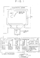
- Fig. 1 is a block diagram showing a first embodiment of the electronic board system according to the present invention.
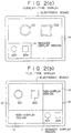
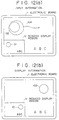
- Figs. 2(a) and 2(b) are each a schematic representation showing an example in which a non-reduced display region and a reduced display region are formed on the writing screen of an electronic board and graphics are displayed on both of the non-reduced display region thereof and the reduced display region thereof.
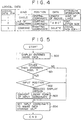
- Fig. 3 is a flowchart showing procedures of processing to be performed by a data processor.
- Fig. 4 is a table showing logical data of results of recognition of image data.
- Fig. 5 is a flowchart showing a detail of procedures of processing a display of input image data.
- Fig. 6 is a schematic representation showing a process for converting data item entered in the reduced display region of the writing screen of the electronic board into a standard coordinate on the non-reduced display region thereof.
- Fig. 7 is a flowchart showing a detail of procedures of processing a display of recognized data.
- Fig. 8 is a schematic representation showing a process for converting a standard coordinate data item located on the non-reduced display region of the electronic board into a coordinate in the reduced display region thereof.
- Figs. 9(a) and 9(b) are each a schematic representation showing an example in which input data is recognized.
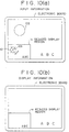
- Figs. 10(a) and 10(b) are each a schematic representation showing an example in which DELETE command is executed.
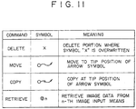
- Fig. 11 is a table showing an example of edit commands.
- Figs. 12(a) and 12(b) are each a schematic representation showing an example in which MOVE command is executed.
- Fig. 13 is a block diagram showing a second embodiment of the electronic board system according to the present invention.
- Fig. 14 is a block diagram showing a third embodiment of the electronic board system according to the present invention, in which a plurality of graphics tablet units are connected.
- Fig. 15 is a block diagram showing a fourth embodiment of the electronic board system according to the present invention, in which an image reader such as a scanner or a facsimile machine is connected.
- Fig. 16 is a block diagram showing a fifth embodiment of the electronic board system according to the present invention, in which a voice recognition device is connected.
- Fig. 17 is a diagram showing an input device management table to be used when a plurality of image input means are connected.
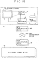
- Fig. 18 is a block diagram showing a sixth embodiment of the electronic board system according to the present invention, in which a plurality of electronic boards are connected with each other through data communication devices.
- Fig. 19 is a block diagram showing a seventh embodiment of the electronic board system according to the present invention, in which the electronic board is connected with a television conference system, that is, a system to make a conference with persons at remote locations through the television conference system.
- a television conference system that is, a system to make a conference with persons at remote locations through the television conference system.
- Fig. 1 is the block diagram showing the first embodiment of the electronic board system according to the present invention.
- the electronic board system comprises an electronic board 1, a data processor 2, a data storage 3, and a display unit 4.
- the electronic board 1 has a writing screen 1a of such a structure that a large number of sensors are arranged and embedded in a matrix form in the rear of the writing screen 1a so as to detect traces of characters, graphics, or the like, which are written on the writing screen 1a with a pointing device 1b.
- the pointing device 1b may be prepared each for different colors or provided with a switch for selecting a color from the different colors, thereby capable of transmitting signals having different frequency of each of the different colors.
- the sensors are arranged so as to respond to the signals for each frequency to thereby distinguish the pointing device 1b for each color from the other pointing devices 1b, on the basis of the frequency transmitted from the pointing device 1b, and to thereby generate color data representing the color of the pointing device 1b that is being employed and coordinate data lines, indicative of the traces of the pointing device 1b, as image data.
- the writing screen 1a of the electronic board 1 may be of an overlap display type and of a tiled display type.
- the writing screen 1a of the overlap display type may be divided into a non-reduced display region 1d and a reduced display region 1c, as shown in Fig. 2(a).
- the screen 1a of the electronic board of the tiled display type may be divided as in a tiled form into a non-reduced display region 1d, a reduced display region 1c, and a non-display region 1e, for example, as shown in Fig. 2(b).
- the reduced display region 1c on the screen 1a of the electronic board 1 is provided with the sensors at a density higher than the other regions on the screen 1a thereof, thereby allowing the image to be displayed clearly without fading when the image entered in the reduced display region 1c is displayed in an enlarged form on the non-reduced display region 1d.
- the data processor 2 comprises an image data entry unit 21 for entry of image data generated from the electronic board 1, an image data storage unit 22 for storing the image data entered into the image data entry unit 21, an image data recognition unit 23 for recognizing characters, graphics, and so on written on the screen 1a on the basis of the image data stored in the image data storage unit 22 and for recognizing the correspondence of the image data relating to a particular trace of the characters, graphics, or the like to either of a plurality of predetermined edit commands, a recognized-data storage unit 24 for storing the recognized characters, graphics, graphics, edit commands, and so on, a recognition command execution unit 25 for editing the recognized characters, graphics, graphics, and so on in accordance with the edit command stored in the recognized-data storage unit 24, and a stored-data display unit 26 for supplying the display unit 4 through an image memory 27 with the edited characters, graphics, and so on, projecting and displaying them onto the non-reduced display region of the writing screen 1a of the electronic board 1 by the display unit 4, and projecting and displaying them in a reduced
- the data processor 2 is so configured as to recognize the characters, graphics, edit commands, and so on, to be written both in the reduced display region 1c of the writing screen 1a and in the non-reduced display region 1d thereof one after another to thereby update the display contents on the screen 1a thereof.
- the image data storage unit 22 comprises two storage unit sections one of which can bring image data into a readable state and the other of which is allowed to be brought into a writable state. While the image data is continuously written in the storage unit section in the writable state from the electronic board 1, the image data written in the previous input cycle is read from the other storage unit section in the readable state to thereby enter the image data into the image data recognition unit 23.
- the storage unit section in the readable state is switched to the writable state and the other storage unit section in the writable state is switched to the readable state, thereby allowing the image data such as the characters, graphics, and so on, written in a manner asynchronous with processing for recognizing image data, to be supplied to the image data recognition unit 23 without losing them, by entering new image data from the electronic board 1.
- the recognized-data storage unit 24 has likewise two storage unit sections one of which is allowed to be brought into a readable state and the other of which is allowed to be brought into a writable state. While the results of recognition of the image data are continuously written into the storage unit sections that is in the writable state, the recognized results of recognition are read in a previous recognition cycle from the other storage unit section in the readable state and entered into the recognition command execution unit 25. As the reading has been terminated, the states of the two storage unit sections are shifted, thereby switching the readable status of the storage unit section to the writable state and the previously writable status of the other storage unit section to the readable state. Consequently, new results of recognition can be written in the newly writable storage unit section to thereby provide the recognition command execution unit 25 with the results of recognition without losing them.
- the recognition command execution unit 25 can read the result of recognition in the recognized-data storage unit 24 in the readable state in synchronization with a cycle of recognition by the image data recognition unit 23 and it can edit the result of recognition, such as the characters, graphics, and so on, in accordance with the edit command, when the edit command was detected in the read results of recognition, and store the edited newest image data in the data storage 3.
- the read results of recognition such as the characters, graphics, and so on are stored intact in the data storage 3.
- the data storage 3 always stores the data corresponding to the newest image projected and displayed on the screen of the electronic board 1 so that the data stored in the data storage 3 can be printed out with a printer when it is to be recorded on paper or the like.
- the stored-data display unit 26 is arranged to read the edited image data stored in the data storage 3 and to display it on the screen of the electronic board 1 through the display unit 4.
- the procedures of display on the electronic board 1 in this case are not restricted to a particular one and they may involve projecting images onto a liquid crystal display unit through an overhead projector, projecting them through a projector, projecting them onto an opaque electronic board from the same direction in which the writer is present, or projecting them onto a transparent electronic board from the direction opposite to the direction in which the writer is present.
- the recognition processing to be performed by the image data recognition unit 23 is performed in accordance with conventional techniques so that a detailed description of the recognition processing will be omitted from the explanation that follows.
- Fig. 3 is the flowchart showing the procedures of the processing to be performed by the data processor 2.
- an image data entry device is selected for reading image data and entering it.
- the image data entry device may be so arranged as to read the image data through an image reading means, such as a scanner or a facsimile machine, in such a manner as will be described hereinafter.
- the electronic board 1 is selected.
- the image data is entered through the image data entry unit 21, which is composed of a coordinate data line representing the traces of characters, graphics, or the like, written on the writing screen 1a of the electronic board 1, and color data representing the color of the traces of the characters, graphics, or the like. Then, the image data is transferred directly to the display unit 4 through the image memory 27 and displayed on the screen 1a of the electronic board 1 prior to the execution of the recognition processing, while the image data is being stored one after another in the image data storage unit 22.
- the image data stored in the image data storage unit 22 is read one after another and supplied to the image data recognition unit 23 to thereby recognize the characters, graphics, edit command, and so on.
- the results of recognition obtained by the image data storage unit 22 are then stored in the recognized-data storage unit 24. More specifically, the results of recognition may be stored in the table, as shown in Fig. 4, showing the logical data of the results of recognition of the image data.
- the results of recognition are provided in units of the characters, graphics, and so on with identification numbers as the logical data and further classified by the kind such as a circle, a line of characters, a command, and so on, by the written position such as a central coordinate, so on, by the data such as the length of a radius of the circle, characters, and so on, and by the attribute information such as the kind of a line of the circle, the kind of a font, letter size, and so on.
- the logical data stored in the recognized-data storage unit 24 is read by the recognition command execution unit 25 to thereby decide to determine whether the read logical data contains the edit command. If the result of decision indicates that the command is contained in the logical data, then the program flow goes to step 305 at which the processing corresponding to the command is called to thereby edit the logical data such as the characters, graphics, and so on and to store the results of recognition in the data storage 3. On the other hand, if it is decided that no command is contained in the read logical data, the logical data read from the recognized-data storage unit 24 are stored intact in the data storage 3.
- the edited image data stored in the data storage 3 is read by the stored-data display unit 26 and supplied to the image memory 27.
- the image memory 27 still stores unprocessed image data that has been entered through the image data entry unit 21, the contents of the image memory 27 are overwritten with the edited image data, that is, the image data prepared by converting the manually written characters, graphics, and so on into block letters or into normal forms. Then, the image data is displayed on the screen of the electronic board 1 through the display unit 4.
- the circle 201 and the square 202 written in solid lines are projected and displayed in the same positions and in the same sizes as those written in broken lines.
- a circle 203 and a square 204, each having the same shape as those displayed on the non-reduced display region 1d yet having a reduced size are projected and displayed on the reduced display region 1c located at the lower portion of the screen 1a of the electronic board 1.
- the characters, graphics, and so on can be written through the pointing device 1b on either of the reduced display region 1c or the non-reduced display region 1d of the screen 1a of the electronic board 1.
- they are written on the non-reduced display region 1d they are written in their reduced sizes and shapes on the reduced display region 1c in the manner as described hereinabove.
- the characters, graphics, and so on written on the reduced display region 1c cannot further be reduced and displayed on the reduced display region 1c of the electronic board 1 as shown in Fig. 2(a); however, they can be displayed on the non-reduced display region 1d by transferring their coordinates to the non-reduced display region 1d.
- the characters, graphics, and so on can be displayed in both of the non-reduced sizes and shapes as well as the reduced sizes and shapes on the so-called tiled screen as shown in Fig. 2(b).
- Fig. 5 is the flowchart showing the detail of the procedures of the image data display processing at step 302 as shown in Fig. 3.
- the image data entered into the image data entry unit 21 is displayed on the display unit 4.
- the manually written image is displayed intact on the writing screen 1a of the electronic board 1 in the position in which it was written.
- the standard mode referred to herein is intended to mean the mode in which no reduced display region 1c is disposed on the writing screen 1a of the electronic board 1.
- the image data entered from the screen 1a of the electronic board 1 is stored in the image data storage unit 22 without causing the coordinates of the image data to be processed.
- step 502 determines if the entered image data exists in a squared region of the reduced display region 1c, as shown in Fig. 6, enclosed by the starting point (c, 0) and the ending point (a, d).
- x2 and y2 may be the standard x- and y-coordinates of the point converted by the formulas (1) and (2) above and transferred into the non-reduced display region 1d of the screen 1a of the electric board 1.
- the coordinates (x1, y1) of the point written with the pointing device 1b in the reduced display region 1c of the writing screen 1a of the electronic board as shown in Fig. 6 the coordinates are converted into the standard coordinates (x2, y2) in the non-reduced display region 1d thereof through the formulas (1) and (2) above.
- the image data storage unit 22 can always store the image data in the coordinate system of the non-reduced display region.
- step 701 it is decided to determine if a standard mode is set which displays image data on a screen 1a having no reduced display region 1c.
- the program flow goes to step 703 at which the coordinates of the logical data stored in the data storage 3 are converted into display signals without processing and they are displayed on the display unit 4.
- step 701 when it is decided at step 701 that a mode having the reduced display region 1c, other than the standard mode, it is necessary to display the image in a reduced size and shape on the reduced display region 1c. Hence, in this case, it is decided to determine if the logical data stored in the data storage 3 exists in the reduced display region 1c, as shown in Fig. 8, enclosed by the starting point (c, 0) and the ending point (a, d).
- the coordinates (u1, v1) of the point written with the pointing device 1b in the non-reduced display region 1d of the writing screen 1a of the electronic board 1 as shown in Fig. 8 the coordinates are converted into the standard coordinates (u2, v2) in the reduced display region 1c thereof through the formulas (3) and (4) above.
- step 702 when it is decided at step 702 that the logical data exists in the reduced display region 1c as defined and delimited hereinabove, the coordinates of the logical data are generated intact into the display unit 4.
- FIG. 9(b) shows an example in which the results obtained by processing the description contents as shown in Fig. 9(a) are displayed on the electronic board 1, that is, in which a circle 903 representing the result of recognition of the manually written circle 901 and a line of characters 904, as indicated by "ABC", representing the result of recognition of the manually written line of characters "ABC” 902, are displayed in the reduced display region 1c. Further, a recognized circle 905 and line of characters "ABC" 906 are displayed at the entire portion on the writing screen 1a of the electronic board 1.
- Figs. 10(a) and 10(b) show an example of displaying an example in which the edit processing is executed with the edit command.
- Fig. 10(a) indicates an example of deleting circles 101 and 102 from the screen 1a of the electronic board 1 by using DELETE command 103, as indicated by symbol "X", in the reduced display region 1c.
- Fig. 10(b) indicates the result of executing the DELETE command 103 so that the circles 101 and 102 have been deleted from the screen 1a of the electronic board 1 as shown in Fig. 10(a), although the line of characters "ABC" remains stored and displayed on the writing screen 1a of the electronic board 1.
- Fig. 11 shows an example of the table containing the edit commands, such as deleting, moving, copying, and retrieving.
- a description will now be made of an example of moving the circle 102 to a predetermined position on the writing screen 1a of the electronic board 1 with reference to Figs. 12(a) and 12(b) by using the MOVE command as shown in Fig. 11.
- the circle 102 is enclosed as shown in Fig. 12(a) with a circular mark of the MOVE command as shown in Fig. 11 and the position to which the circle 102 is intended to be moved is specified by an arrow mark of the MOVE command.
- the circle 102 is transferred to the destination and displayed on the screen 1a of the electronic board 1 in the position specified by the MOVE command, as shown in Fig. 12(b).
- the circle 101 displayed in the reduced display region 1c is transferred to and displayed in the reduced display region 1c in the position corresponding to the destination of the circle 102 on the screen of the electronic board 1 as shown in Fig. 12(b).
- the electronic board system can recognize the characters, graphics, edit commands, and so on, manually written on the writing screen 1a of the electronic board 1, through the image data recognition unit 23 and then edit the characters, graphics, and so on, on the basis of the recognized edit command as well as it can project and display the characters, graphics, and the like on the screen 1a thereof, while they are projected and displayed in their reduced sizes and shapes on the reduced display region 1c disposed at the lower portion of the screen 1a thereof.
- the operator who cannot reach the upper portion of the screen 1a can operate the electronic board 1 in a complex and precise fashion through the reduced display region 1c disposed at the lower portion of the screen 1a of the electronic board 1, thereby taking advantage of the large size and high resolution of the electronic board 1 to a sufficient extent.
- the writer does not shadow the non-reduced display region 1d when the writer operates this system through the reduced display region 1c, thereby allowing the audience to see the display contents without interference from the writer.
- the sensors are embedded in the back of the writing screen 1a of the electronic board 1 so that the electronic board system can be transferred to a different place without difficulty and it can be prepared at relatively low costs.
- the operations such as the deleting operation can be performed in accordance with the edit commands without the use of any special device for performing the delete processing, so that operability of the electronic board system can be improved to a high extent.
- touch sensors or optical sensors may be employed as the sensors for the electronic board 1, which are embedded in the back of the writing screen of the electronic board.
- one data processor 2 is so disposed as to correspond to one screen of the electronic board 1 in this embodiment of the electronic board system according to the present invention.
- the electronic board system may be arranged in such a structure that only one data processor 2 may correspond to a plurality of writing screens of the electronic boards. In this case, the plural electronic boards 1 are disposed in a row.
- the processor 210 comprises an image data entry unit 21 and an image data storage unit 22; the processor 211 comprises an image data recognition unit 23 and a recognized-data storage unit 24; the processor 212 comprises a recognition command execution unit 25; and the processor 213 comprises a stored data display unit 26.
- Each of the processors 210 to 213 is connected with each other and a data storage 3 through a data transmission line 214. It should be noted herein, however, that each of the units may be allocated to any processor as needed or that the processors and/or the units may be connected in any combination as needed.
- the combination of the units as in the second embodiment of the electronic board system according to the present invention can operatively manipulate data in the manner as described hereinabove.
- Fig. 14 shows the third embodiment of the electronic board system according to the present invention, in which a plurality of graphics tablet units 140 and 141 are connected to a data processor 2, in addition to the electronic board 1.
- both of the electronic board 1 and the plural graphics tablet units 140 and 141 are connected with an input controller 142 that in turn is connected with the data processor 2.
- the data processor 2 may be configured in such a manner as the data processor 2 used for the electronic board system of the first embodiment according to the present invention.
- the input controller 142 is so adapted as to select either one of the electronic board 1 or the tablet unit 140 or 141 and the image data generated from the selected device is stored in the image data storage unit 22 of the data processor 2.
- the image data entered from the tablet units 140 and 141 is subjected to the recognition processing in the manner as in the first embodiment, thereby displaying the entered image data on the screen 1a of the electronic board 1.
- the graphics tablet units 140 and 141 may be arranged in such a manner that one of the tablet units is so adapted as to enter image data written manually and the other is so adapted as capable of displaying the manually written image data.
- the arrangement of the tablet units allows the results of execution by the data processor 2 to be displayed on both of the electronic board 1 and the tablet unit having a display function.
- each of the attendants can take part in the meeting with the person using the electronic board 1 and the other attendants by amending what is written on the writing screen of the electronic board 1 by the writer and what is amended with the other attendants.
- This electronic board system can greatly serve as facilitating the meeting.
- Fig. 15 illustrates the electronic board system of the fourth embodiment according to the present invention, in which the image reader such as an image scanner or a facsimile machine is connected with a data processor 2 with which the electronic board 1 in turn is connected.
- an image reader 150 can read data 151, such as characters, graphics, pictures or the like, written or drawn manually with a writing device such as a pencil or a ball point pen, and transmit the read image data to a data processor 2 that processes the image data. The results of recognition of the image data to be made by the data processor 2 is then displayed on the screen of the electronic board 1.
- the arrangement of the electronic board 1 connected with the image reader 150 can allow each of the attendants at a meeting to add an amendment to a draft memorandum, for example, for the meeting, displayed on the screen of the electronic board 1 through the image reader 150. Hence, this arrangement can facilitate the meeting to a great extent.
- the data processor 2 may comprise an image data entry unit 21, an image data storage unit 22, an image data recognition unit 23, a recognized-data storage unit 24, a recognition command execution unit 25, and a stored-data display unit 26, and each of the units may have substantially the same functions as those provided for the electronic board system according to the first embodiment of the present invention.
- voices are entered into a voice recognition device 160 through a microphone 161.
- the voice recognition device 160 is so arranged as to recognize the correspondence of the input voices to words, graphics, edit commands, or the like and to transmit the results of recognition to the recognized-data storage unit 24 of the data processor 2 for storing.
- the edit commands are contained in the results of recognition, the edit commands are executed by the recognition command execution unit 25 of the data processor 2 to thereby display the result of execution on the screen of the electronic board 1.
- each of the data processors 2 may be arranged so as to manage each of the input devices on the basis of an input device management table 170 as shown in Fig. 17.
- the input device management table 170 contains data, such as the device identification numbers for the input devices, the kinds of the devices, the addresses indicating the connection of the input devices with the processors, the status indicative of the current states of the input devices, the display modes indicative of the overlap display type, the tiled display type and the standard display type, and the starting positions and the ending positions of the reduced display region.
- Fig. 18 shows the sixth embodiment of the electronic board system according to the present invention, in which a plurality of electronic board systems are connected with each other through a plurality of data communication devices.
- an electronic board system 1A having the same configuration as shown in Fig. 1 is connected through a data communication device 180 with a data transmission device 182, serving as a local area network or a global area network, with which an electronic board system 1B having the same configuration as shown in Fig. 1 is connected through another data communication device 181.
- the image data can be exchanged between the electronic board systems 1A and 1B disposed at remote locations so that a meeting can be held while exchanging the image written on the screen of the electronic board 1 between or among the electronic board systems disposed at remote locations.
- Fig. 19 shows the seventh embodiment of the electronic board system according to the present invention, in which the electronic board system is connected with a television conference system.
- a television conference system 1900 comprises a microphone 1901, a speaker 1902, a voice controller 1903, a voice transmission unit 1904, a camera 1905, an operation unit 1906, a monitor 1907, a graphic controller 1908, and an image transmission unit 1909.
- the television conference system 1900 may be connected with another television conference system 1910 disposed at a different location via the data transmission unit 182 with which the interactive electronic board systems 1A and 1B, each having a recognition function, as shown in Fig. 18, are connected through the data communication devices 180 and 181, respectively.
- the arrangement of the electronic board systems and the television conference systems allows the data written on the screen of the electronic board 1 to be exchanged at remote locations during a meeting through a television set.
- the electronic board systems comprises the pointing device, the plural sensors for detecting the traces of an image written on the screen with said pointing device, which are embedded in the rear of the screen; the first storage means for storing the traces of the image detected by said sensors as image data consisting of the sequence of coordinate data; the recognition means for recognizing the image written on the screen on the basis of the image data stored in said first storage means and at the same time for recognizing whether the image data relating to the particular traces corresponds to either one of a plurality of the predetermined edit commands; the second storage means for storing the recognized image or the recognized edit command; the command execution means for editing the recognized image in accordance with the edit command stored in said second storage means; and the projection and display means for projecting and displaying the edited image onto the writing screen of the electronic board and at the same time for projecting and displaying the edited image in the reduced form on a region disposed at the lower portion of the screen of the electronic board.
- the electronic board systems according to the present invention is adapted so as to recognize the image and the edit command to be represented in the reduced display region of the screen of the electronic board and in the non-reduced display region thereof and to update the display content to be displayed one after another on the screen of the electronic board. Further, the electronic board systems according to the present invention allows even the person failing to reach the upper portion of the screen of the electronic board to perform complex and precise operations through the reduced display region located at the lower portion of the screen of the electronic board, thereby taking advantage of the large size and the high resolution of the electronic board.
- the electronic board systems according to the present invention offer the advantage that they can be operated through either one of the non-reduced display region or the reduced display region.
- the person writing the image on the reduced display region may not shadow the non-reduced display region so that the audience can see the image to a full extent through the non-reduced display region without interference from the writer.
- the sensors are embedded in the rear of the screen of the electronic board so that the electronic board system can be moved or transferred without difficulty and the electronic board system can be prepared at reasonably low costs.
- the electronic board systems according to the present invention allow the various operations to be performed through the edit commands, for example, the deleting operations, to be performed on the basis of a delete command, so that an operating device such as a deleting device of a special sort is not required, thereby improving operability.
- the electronic board systems according to the present invention can recognize the image data written on the screen of the electronic board as the logical data having the meaning for business of the user or as the command for the logical data and it can perform a variety of the operations of inserting, deleting, changing, printing, inspecting, transferring, saving, copying, and distributing, for example, to thereby display the results obtained by the various processing at real time on the writing screen of the electronic board.
- the electronic board systems can further present the advantages, among others, that the meeting time and the times of the meeting can be reduced, quality of the meeting results can be improved, and expenses required for the meeting to be held with persons located at remote locations, such as travelling expenses and so on, can be reduced.
- the electronic board systems according to the present invention allow the recognition processing to be changed in accordance with the business of each of the users so that the scope of application of the electronic board system can be expanded.
- the electronic board systems according to the present invention can improve efficiency in the meetings to be held between or among remote locations and reduce expenses required for the meetings by connecting the plurality of the electronic boards with the data transmission device or the television conference systems.
- the data processor for the electronic board system according to the present invention having the recognition processing function loaded thereon can be connected with an electronic board and/or a display unit of a conventional type, thereby readily realizing a system that is low at costs, high in quality, and easy to move or carry.
Abstract
Description
- The present invention relates to an electronic board system so adapted as to recognize characters written as well as images, such as graphics and pictures, drawn on a screen of an electronic board and to display the results of recognition on the screen thereof by projecting it onto the screen thereof.
- It is general upon a meeting that the attendants discuss a preset issue on the basis of papers prepared in advance and/or information written on blackboard or whiteboard on site, they check the contents of the issue and amend them as needed, they record the conclusion or interim results, and they distribute a copy of the results of the meeting to the attendants and persons concerned.
- Electronic board systems are known as convenient means capable of facilitating the meeting. Such electronic board systems are disclosed, for example, in Japanese Patent Examined Publication (kokoku) No. 3-26,855 and Japanese Patent Unexamined Publication (kokai) Nos. 2-200,499, 1-125,296, 63-209,999, and 62-52,630.
- The electronic board system as disclosed in Japanese Patent Examined Publication (kokoku) No. 3-26,855 is configured in such a manner that characters, graphics, etc. written or drawn on a screen of the electronic board system with and through a writing device with an oscillator equipped therein are detected as a sequence of data of coordinate positions through a sensor that is embedded in the electronic board; the sequence of the coordinate positions data is stored in image memory; the traces of the characters, graphics, etc. indicated by the sequence of the coordinate positions data are displayed as the characters, graphics, etc. on a display screen; the sequence of the coordinate positions data existing in a given region is deleted from the corresponding image memory with and through a deleting device with an oscillator equipped therein by performing operations for deleting the displayed coordinate positions data from the given region on a screen of the electronic board; and the characters, graphics, etc. displayed in the given region are deleted from the display screen.
- The electronic board system as disclosed in Japanese Patent Unexamined Publication (kokai) No. 2-200,499 is so arranged as to recognize characters, graphics, etc. written manually with a writing device on its board through a recognition processing device and to record the result of recognition on recording paper.
- Further, the electronic board system as disclosed in Japanese Patent Unexamined Publication (kokai) No. 63-209,999 is configured in such a fashion that characters written manually are read through an image reader and recognized with an OCR, and the result of recognition is displayed on a screen of the electronic board in an enlarged manner.
- In addition, the electronic board system as disclosed in Japanese Patent Unexamined Publication (kokai) No. 1-125,296 is so configured as to recognize voices entered in a voice recognition device as letters and display the words corresponding to the recognized voices on the screen of the electronic board.
- Furthermore, Japanese Patent Unexamined Publication (kokai) No. 62-52,630 discloses the electronic board system which is so configured as to recognize characters and graphics entered manually on a transparent graphics tablet device through a stylus input device and to display the result of recognition on a display device, such as a liquid crystal screen, integral with the graphics tablet device.
- On top of those as described hereinabove, a device is proposed in an article entitled "A New Face of User Interface: Features of Two Big OSs for Input through Pens" (a magazine "Nikkei Byte", April, 1991, pages 233 to 238), which can translate particular traces of a pen on a graphics tablet device integral with a liquid crystal screen into edit commands and edit the corresponding image displayed on the liquid crystal screen.
- Furthermore, as introduced in a leaflet of "Smart 2000 Series Products" of Smart Technology, Inc. in Canada, a data processing system is proposed which allows the user to perform all operations in an interactive manner on a screen of the electronic board by recognizing characters, graphics, commands, etc. written through a pointing device on the screen of the electronic board and projecting the result of recognition or the result of execution of the commands through an LCD projector on the screen thereof and displaying it on a real time basis thereon.
- Those electronic board systems as described hereinabove, which are arranged to display the result of recognition through the voices or the result of recognition through the OCR on the screen of the electronic board, suffer from the disadvantage that, although characters or graphics can be corrected on the electronic board, the result of correction cannot be recorded.
- On the other hand, the electronic board systems having the sensors embedded into the electronic board or having the function of recognition added can record the result of correction; however, the former requires the use of the deleting device of a special type that is different from the pointing device so that it is laborious to distinguish the deleting device from the pointing device or vice versa, whenever characters, graphics, etc. are to be deleted or written, and the latter requires the function of recognition on a large scale and the weight of the electronic board system becomes so heavy that it is very inconvenient to move the electronic board system to another place.
- Further, the device using the graphics tablet device with the liquid crystal screen is developed solely for use with an individual person so that a display device utilizing the graphics tablet device with the sensors and so on embedded therein and the liquid crystal screen, which requires precision processing, should be made larger in size and that the graphics tablet device should be integrated with the liquid crystal screen so that such electronic board system presents the problems that costs of manufacture become expensive, a quality may become instable, and it is difficult to move.
- In addition, for such electronic board systems of the Smart 2000 series as projecting onto the screen of the electronic board the display contents of a personal computer which is so designed as for an individual person to use while facing the display screen, they suffer from the disadvantages that complex and precise operations cannot be performed because a portion which a person writing on the electronic board shadows cannot be seen by the writing person itself and other persons and that the size and resolution of the electronic board cannot be utilized to a sufficient extent because some persons cannot reach and execute MENU commands or display data items, which are located at an upper portion of the electronic board.
- Therefore, the object of the present invention is to provide an electronic board system that can be ready to move, that does not require a pointing device to be distinguished from an deleting device, that can be operated in a complex and precise fashion even if a person using the electronic board system could not reach the upper portion of the electronic board, and that can be prepared at low costs.
- In order to achieve the above-mentioned object, the present invention consists of an electronic board system comprising:
a pointing device;
a plurality of sensors for detecting a trace of a character, a graphic, or the like, written on a writing screen with said pointing device, which are embedded in the back of the writing screen;
first storage means for storing the trace detected by said sensors as image data consisting of a sequence of coordinate data;
recognition means for recognizing the character, graphic, or the like written on the writing screen on the basis of the image data stored in said first storage means and for recognizing whether the image data relating to a particular trace corresponds to either of a plurality of predetermined edit commands;
second storage means for storing the recognized character, graphic, the recognized edit command, and so on;
command execution means for editing the recognized character, graphic, or the like in accordance with the edit command stored in said second storage means; and
projection and display means for projecting and displaying the edited character, graphic, or the like onto the writing screen of the electronic board and for projecting and displaying the edited character, graphic, or the like in a reduced form at a lower portion of the writing screen of the electronic board;
wherein the character, graphic, or the like and the edit command to be represented in a reduced display region of the writing screen of the electronic board and in a non-reduced display region thereof can be recognized one after another; and
a display content to be displayed on the screen is updated one after another. - The arrangement of the electronic board system as described hereinabove allows the characters, graphics, edit commands, and so on, written on the writing screen of the electronic board to be recognized by the recognition means and the characters, graphics, and so on to be edited in accordance with the recognized edit commands and the edited characters, graphics, and so on to be projected and displayed on a non-reduced display region of the writing screen of the electronic board and at the same time to be projected and displayed in a reduced form on a reduced display region located at the lower portion of the writing screen on the electronic board as well. Hence, even such a person as failing to reach the upper portion of the screen on the electronic board can perform complex and precise operations in the reduced display region to thereby utilize the size and resolution of the electronic board to a sufficient extent. Further, the electronic board system according to the present invention having the configuration as described hereinabove can be operated at the non-reduced display region of the writing screen on the electronic board as well as at the reduced display region thereof; hence, if the operations would be performed only at the reduced display region of the writing screen, the non-reduced display region thereof can be seen by other persons without causing the person handling the electronic board system to shadow the non-reduced display region of the writing screen on the electronic board.
- Further, the sensors are embedded in the back of the writing screen of the electronic board so that the electronic board system itself can be moved or carried without difficulty and the electronic board system can be prepared at low costs.
- In addition, such operations as deleting and so on can be executed in accordance with the edit commands so that any deleting device of a special type is not required, thereby improving operability.
- Fig. 1 is a block diagram showing a first embodiment of the electronic board system according to the present invention.
- Figs. 2(a) and 2(b) are each a schematic representation showing an example in which a non-reduced display region and a reduced display region are formed on the writing screen of an electronic board and graphics are displayed on both of the non-reduced display region thereof and the reduced display region thereof.
- Fig. 3 is a flowchart showing procedures of processing to be performed by a data processor.
- Fig. 4 is a table showing logical data of results of recognition of image data.
- Fig. 5 is a flowchart showing a detail of procedures of processing a display of input image data.
- Fig. 6 is a schematic representation showing a process for converting data item entered in the reduced display region of the writing screen of the electronic board into a standard coordinate on the non-reduced display region thereof.
- Fig. 7 is a flowchart showing a detail of procedures of processing a display of recognized data.
- Fig. 8 is a schematic representation showing a process for converting a standard coordinate data item located on the non-reduced display region of the electronic board into a coordinate in the reduced display region thereof.
- Figs. 9(a) and 9(b) are each a schematic representation showing an example in which input data is recognized.
- Figs. 10(a) and 10(b) are each a schematic representation showing an example in which DELETE command is executed.
- Fig. 11 is a table showing an example of edit commands.
- Figs. 12(a) and 12(b) are each a schematic representation showing an example in which MOVE command is executed.
- Fig. 13 is a block diagram showing a second embodiment of the electronic board system according to the present invention.
- Fig. 14 is a block diagram showing a third embodiment of the electronic board system according to the present invention, in which a plurality of graphics tablet units are connected.
- Fig. 15 is a block diagram showing a fourth embodiment of the electronic board system according to the present invention, in which an image reader such as a scanner or a facsimile machine is connected.
- Fig. 16 is a block diagram showing a fifth embodiment of the electronic board system according to the present invention, in which a voice recognition device is connected.
- Fig. 17 is a diagram showing an input device management table to be used when a plurality of image input means are connected.
- Fig. 18 is a block diagram showing a sixth embodiment of the electronic board system according to the present invention, in which a plurality of electronic boards are connected with each other through data communication devices.
- Fig. 19 is a block diagram showing a seventh embodiment of the electronic board system according to the present invention, in which the electronic board is connected with a television conference system, that is, a system to make a conference with persons at remote locations through the television conference system.
- Fig. 1 is the block diagram showing the first embodiment of the electronic board system according to the present invention. The electronic board system comprises an
electronic board 1, adata processor 2, adata storage 3, and adisplay unit 4. - The
electronic board 1 has a writing screen 1a of such a structure that a large number of sensors are arranged and embedded in a matrix form in the rear of the writing screen 1a so as to detect traces of characters, graphics, or the like, which are written on the writing screen 1a with a pointing device 1b. - The pointing device 1b may be prepared each for different colors or provided with a switch for selecting a color from the different colors, thereby capable of transmitting signals having different frequency of each of the different colors. On the other hand, the sensors are arranged so as to respond to the signals for each frequency to thereby distinguish the pointing device 1b for each color from the other pointing devices 1b, on the basis of the frequency transmitted from the pointing device 1b, and to thereby generate color data representing the color of the pointing device 1b that is being employed and coordinate data lines, indicative of the traces of the pointing device 1b, as image data.
- The writing screen 1a of the
electronic board 1 may be of an overlap display type and of a tiled display type. The writing screen 1a of the overlap display type may be divided into a non-reduced display region 1d and a reduced display region 1c, as shown in Fig. 2(a). On the other hand, the screen 1a of the electronic board of the tiled display type may be divided as in a tiled form into a non-reduced display region 1d, a reduced display region 1c, and a non-display region 1e, for example, as shown in Fig. 2(b). The reduced display region 1c on the screen 1a of theelectronic board 1 is provided with the sensors at a density higher than the other regions on the screen 1a thereof, thereby allowing the image to be displayed clearly without fading when the image entered in the reduced display region 1c is displayed in an enlarged form on the non-reduced display region 1d. - The
data processor 2 comprises an imagedata entry unit 21 for entry of image data generated from theelectronic board 1, an imagedata storage unit 22 for storing the image data entered into the imagedata entry unit 21, an imagedata recognition unit 23 for recognizing characters, graphics, and so on written on the screen 1a on the basis of the image data stored in the imagedata storage unit 22 and for recognizing the correspondence of the image data relating to a particular trace of the characters, graphics, or the like to either of a plurality of predetermined edit commands, a recognized-data storage unit 24 for storing the recognized characters, graphics, graphics, edit commands, and so on, a recognitioncommand execution unit 25 for editing the recognized characters, graphics, graphics, and so on in accordance with the edit command stored in the recognized-data storage unit 24, and a stored-data display unit 26 for supplying thedisplay unit 4 through animage memory 27 with the edited characters, graphics, and so on, projecting and displaying them onto the non-reduced display region of the writing screen 1a of theelectronic board 1 by thedisplay unit 4, and projecting and displaying them in a reduced form onto the reduced display region located at a lower portion of the screen 1a. With the arrangement as described hereinabove, thedata processor 2 is so configured as to recognize the characters, graphics, edit commands, and so on, to be written both in the reduced display region 1c of the writing screen 1a and in the non-reduced display region 1d thereof one after another to thereby update the display contents on the screen 1a thereof. - The image
data storage unit 22 comprises two storage unit sections one of which can bring image data into a readable state and the other of which is allowed to be brought into a writable state. While the image data is continuously written in the storage unit section in the writable state from theelectronic board 1, the image data written in the previous input cycle is read from the other storage unit section in the readable state to thereby enter the image data into the imagedata recognition unit 23. As the reading has been terminated, the storage unit section in the readable state is switched to the writable state and the other storage unit section in the writable state is switched to the readable state, thereby allowing the image data such as the characters, graphics, and so on, written in a manner asynchronous with processing for recognizing image data, to be supplied to the imagedata recognition unit 23 without losing them, by entering new image data from theelectronic board 1. - The recognized-
data storage unit 24 has likewise two storage unit sections one of which is allowed to be brought into a readable state and the other of which is allowed to be brought into a writable state. While the results of recognition of the image data are continuously written into the storage unit sections that is in the writable state, the recognized results of recognition are read in a previous recognition cycle from the other storage unit section in the readable state and entered into the recognitioncommand execution unit 25. As the reading has been terminated, the states of the two storage unit sections are shifted, thereby switching the readable status of the storage unit section to the writable state and the previously writable status of the other storage unit section to the readable state. Consequently, new results of recognition can be written in the newly writable storage unit section to thereby provide the recognitioncommand execution unit 25 with the results of recognition without losing them. - The recognition
command execution unit 25 can read the result of recognition in the recognized-data storage unit 24 in the readable state in synchronization with a cycle of recognition by the imagedata recognition unit 23 and it can edit the result of recognition, such as the characters, graphics, and so on, in accordance with the edit command, when the edit command was detected in the read results of recognition, and store the edited newest image data in thedata storage 3. On the other hand, if no edit command was detected in the read results of recognition, the read results of recognition such as the characters, graphics, and so on are stored intact in thedata storage 3. Hence, thedata storage 3 always stores the data corresponding to the newest image projected and displayed on the screen of theelectronic board 1 so that the data stored in thedata storage 3 can be printed out with a printer when it is to be recorded on paper or the like. - The stored-
data display unit 26 is arranged to read the edited image data stored in thedata storage 3 and to display it on the screen of theelectronic board 1 through thedisplay unit 4. The procedures of display on theelectronic board 1 in this case are not restricted to a particular one and they may involve projecting images onto a liquid crystal display unit through an overhead projector, projecting them through a projector, projecting them onto an opaque electronic board from the same direction in which the writer is present, or projecting them onto a transparent electronic board from the direction opposite to the direction in which the writer is present. - The recognition processing to be performed by the image
data recognition unit 23 is performed in accordance with conventional techniques so that a detailed description of the recognition processing will be omitted from the explanation that follows. - Fig. 3 is the flowchart showing the procedures of the processing to be performed by the
data processor 2. - First, at
step 301, an image data entry device is selected for reading image data and entering it. The image data entry device may be so arranged as to read the image data through an image reading means, such as a scanner or a facsimile machine, in such a manner as will be described hereinafter. In the first embodiment, theelectronic board 1 is selected. - Then, at
step 302, the image data is entered through the imagedata entry unit 21, which is composed of a coordinate data line representing the traces of characters, graphics, or the like, written on the writing screen 1a of theelectronic board 1, and color data representing the color of the traces of the characters, graphics, or the like. Then, the image data is transferred directly to thedisplay unit 4 through theimage memory 27 and displayed on the screen 1a of theelectronic board 1 prior to the execution of the recognition processing, while the image data is being stored one after another in the imagedata storage unit 22. - Further, at
step 303, the image data stored in the imagedata storage unit 22 is read one after another and supplied to the imagedata recognition unit 23 to thereby recognize the characters, graphics, edit command, and so on. - The results of recognition obtained by the image
data storage unit 22 are then stored in the recognized-data storage unit 24. More specifically, the results of recognition may be stored in the table, as shown in Fig. 4, showing the logical data of the results of recognition of the image data. The results of recognition are provided in units of the characters, graphics, and so on with identification numbers as the logical data and further classified by the kind such as a circle, a line of characters, a command, and so on, by the written position such as a central coordinate, so on, by the data such as the length of a radius of the circle, characters, and so on, and by the attribute information such as the kind of a line of the circle, the kind of a font, letter size, and so on. It can be noted herein that the attribute information on the DELETE command is represented by logical data ID#=1, as shown in Fig. 4, so that the DELETE command is intended to mean the command for deleting the image of the circle having theID # 1. - Hence, at
step 304, the logical data stored in the recognized-data storage unit 24 is read by the recognitioncommand execution unit 25 to thereby decide to determine whether the read logical data contains the edit command. If the result of decision indicates that the command is contained in the logical data, then the program flow goes to step 305 at which the processing corresponding to the command is called to thereby edit the logical data such as the characters, graphics, and so on and to store the results of recognition in thedata storage 3. On the other hand, if it is decided that no command is contained in the read logical data, the logical data read from the recognized-data storage unit 24 are stored intact in thedata storage 3. - Then, at
step 306, the edited image data stored in thedata storage 3 is read by the stored-data display unit 26 and supplied to theimage memory 27. Although at this time theimage memory 27 still stores unprocessed image data that has been entered through the imagedata entry unit 21, the contents of theimage memory 27 are overwritten with the edited image data, that is, the image data prepared by converting the manually written characters, graphics, and so on into block letters or into normal forms. Then, the image data is displayed on the screen of theelectronic board 1 through thedisplay unit 4. - It is then decided to determine if the display processing was over. When the result of decision indicates that the display processing is over, then the processes has been terminated. On the other hand, when it is decided that the display processing is not over yet, then the program flow returns to step 301 and the processes are repeated at
step 307 until an instruction to terminate the process is issued. - More specifically, for example, when the pointing device 1b is operated so as to write a
circle 201 and a square 202 in broken lines on the non-reduced display region 1d of the writing screen of theelectronic board 1 as indicated in the display system of the overlap display type as shown in Fig. 2(a), thecircle 201 and the square 202 written in solid lines are projected and displayed in the same positions and in the same sizes as those written in broken lines. At the same time, acircle 203 and a square 204, each having the same shape as those displayed on the non-reduced display region 1d yet having a reduced size, are projected and displayed on the reduced display region 1c located at the lower portion of the screen 1a of theelectronic board 1. - The characters, graphics, and so on can be written through the pointing device 1b on either of the reduced display region 1c or the non-reduced display region 1d of the screen 1a of the
electronic board 1. When they are written on the non-reduced display region 1d, they are written in their reduced sizes and shapes on the reduced display region 1c in the manner as described hereinabove. On the other hand, the characters, graphics, and so on written on the reduced display region 1c cannot further be reduced and displayed on the reduced display region 1c of theelectronic board 1 as shown in Fig. 2(a); however, they can be displayed on the non-reduced display region 1d by transferring their coordinates to the non-reduced display region 1d. - Like on the screen of the overlap display type as shown in Fig. 2(a), the characters, graphics, and so on can be displayed in both of the non-reduced sizes and shapes as well as the reduced sizes and shapes on the so-called tiled screen as shown in Fig. 2(b). The non-display region 1e in the screen 1a of the
electronic board 1 as shown in Fig. 2(b), however, is so arranged as not to display any information of the characters, graphics, and so on. - Fig. 5 is the flowchart showing the detail of the procedures of the image data display processing at
step 302 as shown in Fig. 3. First, atstep 500, the image data entered into the imagedata entry unit 21 is displayed on thedisplay unit 4. The manually written image is displayed intact on the writing screen 1a of theelectronic board 1 in the position in which it was written. - Then, at
step 501, it is decided to determine if a standard mode is set. The standard mode referred to herein is intended to mean the mode in which no reduced display region 1c is disposed on the writing screen 1a of theelectronic board 1. When it is decided that the standard mode is set, the image data entered from the screen 1a of theelectronic board 1 is stored in the imagedata storage unit 22 without causing the coordinates of the image data to be processed. - On the other hand, when a mode other than the standard mode is set, which is provided with the reduced display region 1c, it is decided at
step 502 to determine if the entered image data exists in a squared region of the reduced display region 1c, as shown in Fig. 6, enclosed by the starting point (c, 0) and the ending point (a, d). When the decision gives the result that the image data exists in the reduced display region 1c, that is, when it is decided that the pointing device 1b was operated in the reduced display region 1c, then it is decided that the input coordinates are to be corrected and the program flow goes to step 503 at which the linear form of the coordinates of the input image data is converted on the basis of the formulas (1) and (2) as follows:


where x₁ and y₁ may be the x- and y-coordinates of the point written in the reduced display region 1c of Fig. 6 with the pointing device 1b; and
x₂ and y₂ may be the standard x- and y-coordinates of the point converted by the formulas (1) and (2) above and transferred into the non-reduced display region 1d of the screen 1a of theelectric board 1. - For instance, when it is decided that the coordinates (x₁, y₁) of the point written with the pointing device 1b in the reduced display region 1c of the writing screen 1a of the electronic board as shown in Fig. 6, the coordinates are converted into the standard coordinates (x₂, y₂) in the non-reduced display region 1d thereof through the formulas (1) and (2) above.
- To the contrary, when it is decided at
step 502 that the entered image data does not exist in the squared region as defined and delimited hereinabove, that is, when it is decided that the pointing device 1b is operated in the non-reduced display region 1d on the screen 1a of theelectronic board 1, the coordinates of the entered image data are stored intact in the imagedata storage unit 22. Hence, the imagedata storage unit 22 can always store the image data in the coordinate system of the non-reduced display region. - A detailed description will now be made of the procedures of the recognized data display processing at
step 306 in accordance with the flowchart as shown in Fig. 7. - First, at
step 701, it is decided to determine if a standard mode is set which displays image data on a screen 1a having no reduced display region 1c. When the result of decision indicates that the standard mode is set, on the one hand, then the program flow goes to step 703 at which the coordinates of the logical data stored in thedata storage 3 are converted into display signals without processing and they are displayed on thedisplay unit 4. - On the other hand, when it is decided at
step 701 that a mode having the reduced display region 1c, other than the standard mode, it is necessary to display the image in a reduced size and shape on the reduced display region 1c. Hence, in this case, it is decided to determine if the logical data stored in thedata storage 3 exists in the reduced display region 1c, as shown in Fig. 8, enclosed by the starting point (c, 0) and the ending point (a, d). When the decision atstep 701 gives the result that the logical data does not exist in the defined region, it is necessary to correct the coordinates of the logical data so that the program flow goes to step 702 at which the linear form of the coordinates of the logical data is converted on the basis of formulas (3) and (4) as follows:


where u₁ and v₁ may be the x- and y-coordinates of the point written in the non-reduced display region 1d of Fig. 8 with the pointing device 1b; and
u₂ and v₂ may be the standard x- and y-coordinates of the point converted by formulas (3) and (4) above and transferred into the reduced display region 1c of the screen 1a of theelectric board 1. - For instance, when it is decided that the coordinates (u₁, v₁) of the point written with the pointing device 1b in the non-reduced display region 1d of the writing screen 1a of the
electronic board 1 as shown in Fig. 8, the coordinates are converted into the standard coordinates (u₂, v₂) in the reduced display region 1c thereof through the formulas (3) and (4) above. - On the other hand, when it is decided at
step 702 that the logical data exists in the reduced display region 1c as defined and delimited hereinabove, the coordinates of the logical data are generated intact into thedisplay unit 4. - It should be noted herein that, when the location of the reduced display region 1c and the non-reduced display region 1d on the writing screen 1a of the
electronic board 1 differ from those as shown in Figs. 6 and 8, the formulas for converting the linear forms of the image data and the logical data should be changed in accordance with the positions of the original points the direction of their coordinates and that the size, number and position of the reduced display region 1c may be set in an optional manner. - A description will now be made of an example in which a circle, as indicated by
reference numeral 901, and characters "ABC", as indicated byreference numeral 902, are written manually with the pointing device 1b in the reduced display region 1c on the writing screen 1a of theelectronic board 1 having an overlap-type display function as shown in Fig. 9(a). Fig. 9(b) shows an example in which the results obtained by processing the description contents as shown in Fig. 9(a) are displayed on theelectronic board 1, that is, in which acircle 903 representing the result of recognition of the manually writtencircle 901 and a line ofcharacters 904, as indicated by "ABC", representing the result of recognition of the manually written line of characters "ABC" 902, are displayed in the reduced display region 1c. Further, a recognizedcircle 905 and line of characters "ABC" 906 are displayed at the entire portion on the writing screen 1a of theelectronic board 1. - Figs. 10(a) and 10(b) show an example of displaying an example in which the edit processing is executed with the edit command. Fig. 10(a) indicates an example of deleting
circles electronic board 1 by usingDELETE command 103, as indicated by symbol "X", in the reduced display region 1c. Fig. 10(b) indicates the result of executing theDELETE command 103 so that thecircles electronic board 1 as shown in Fig. 10(a), although the line of characters "ABC" remains stored and displayed on the writing screen 1a of theelectronic board 1. - Fig. 11 shows an example of the table containing the edit commands, such as deleting, moving, copying, and retrieving. A description will now be made of an example of moving the
circle 102 to a predetermined position on the writing screen 1a of theelectronic board 1 with reference to Figs. 12(a) and 12(b) by using the MOVE command as shown in Fig. 11. In this case, thecircle 102 is enclosed as shown in Fig. 12(a) with a circular mark of the MOVE command as shown in Fig. 11 and the position to which thecircle 102 is intended to be moved is specified by an arrow mark of the MOVE command. As a result, thecircle 102 is transferred to the destination and displayed on the screen 1a of theelectronic board 1 in the position specified by the MOVE command, as shown in Fig. 12(b). Likewise, thecircle 101 displayed in the reduced display region 1c is transferred to and displayed in the reduced display region 1c in the position corresponding to the destination of thecircle 102 on the screen of theelectronic board 1 as shown in Fig. 12(b). - The electronic board system according to the embodiment of the present invention as described hereinabove can recognize the characters, graphics, edit commands, and so on, manually written on the writing screen 1a of the
electronic board 1, through the imagedata recognition unit 23 and then edit the characters, graphics, and so on, on the basis of the recognized edit command as well as it can project and display the characters, graphics, and the like on the screen 1a thereof, while they are projected and displayed in their reduced sizes and shapes on the reduced display region 1c disposed at the lower portion of the screen 1a thereof. Hence, the operator who cannot reach the upper portion of the screen 1a can operate theelectronic board 1 in a complex and precise fashion through the reduced display region 1c disposed at the lower portion of the screen 1a of theelectronic board 1, thereby taking advantage of the large size and high resolution of theelectronic board 1 to a sufficient extent. Further, as the operations can be made through either of the reduced display region 1c or the non-reduced display region 1d, the writer does not shadow the non-reduced display region 1d when the writer operates this system through the reduced display region 1c, thereby allowing the audience to see the display contents without interference from the writer. - In addition, the sensors are embedded in the back of the writing screen 1a of the
electronic board 1 so that the electronic board system can be transferred to a different place without difficulty and it can be prepared at relatively low costs. - Furthermore, the operations such as the deleting operation can be performed in accordance with the edit commands without the use of any special device for performing the delete processing, so that operability of the electronic board system can be improved to a high extent.
- When the characters, graphics, and so on are displayed in black and white, a variety of the edit processing can be performed with only one kind of the pointing device 1b without using different kinds of pointing devices.
- Further, touch sensors or optical sensors may be employed as the sensors for the
electronic board 1, which are embedded in the back of the writing screen of the electronic board. - In addition, one
data processor 2 is so disposed as to correspond to one screen of theelectronic board 1 in this embodiment of the electronic board system according to the present invention. The electronic board system, however, may be arranged in such a structure that only onedata processor 2 may correspond to a plurality of writing screens of the electronic boards. In this case, the pluralelectronic boards 1 are disposed in a row. - Now, a description will be made of the electronic board system according to the second embodiment of the present invention as shown in Fig. 13, which is provided with a
data processor 2 having a plurality ofprocessors 210 to 213. Theprocessor 210 comprises an imagedata entry unit 21 and an imagedata storage unit 22; theprocessor 211 comprises an imagedata recognition unit 23 and a recognized-data storage unit 24; theprocessor 212 comprises a recognitioncommand execution unit 25; and theprocessor 213 comprises a storeddata display unit 26. Each of theprocessors 210 to 213 is connected with each other and adata storage 3 through adata transmission line 214. It should be noted herein, however, that each of the units may be allocated to any processor as needed or that the processors and/or the units may be connected in any combination as needed. The combination of the units as in the second embodiment of the electronic board system according to the present invention can operatively manipulate data in the manner as described hereinabove. - Fig. 14 shows the third embodiment of the electronic board system according to the present invention, in which a plurality of
graphics tablet units data processor 2, in addition to theelectronic board 1. In the electronic board system of this embodiment, both of theelectronic board 1 and the pluralgraphics tablet units input controller 142 that in turn is connected with thedata processor 2. Thedata processor 2 may be configured in such a manner as thedata processor 2 used for the electronic board system of the first embodiment according to the present invention. Theinput controller 142 is so adapted as to select either one of theelectronic board 1 or thetablet unit data storage unit 22 of thedata processor 2. The image data entered from thetablet units electronic board 1. - The
graphics tablet units data processor 2 to be displayed on both of theelectronic board 1 and the tablet unit having a display function. - When the
graphics tablet units electronic board 1 and the other attendants by amending what is written on the writing screen of theelectronic board 1 by the writer and what is amended with the other attendants. This electronic board system can greatly serve as facilitating the meeting. - Fig. 15 illustrates the electronic board system of the fourth embodiment according to the present invention, in which the image reader such as an image scanner or a facsimile machine is connected with a
data processor 2 with which theelectronic board 1 in turn is connected. With the electronic board system according to the fourth embodiment of the present invention, animage reader 150 can readdata 151, such as characters, graphics, pictures or the like, written or drawn manually with a writing device such as a pencil or a ball point pen, and transmit the read image data to adata processor 2 that processes the image data. The results of recognition of the image data to be made by thedata processor 2 is then displayed on the screen of theelectronic board 1. - The arrangement of the
electronic board 1 connected with theimage reader 150 can allow each of the attendants at a meeting to add an amendment to a draft memorandum, for example, for the meeting, displayed on the screen of theelectronic board 1 through theimage reader 150. Hence, this arrangement can facilitate the meeting to a great extent. - Furthermore, a description will be made of the fifth embodiment of the electronic board system according to the present invention, in which a voice recognition device or a speech recognition device is connected with a
data processor 2. Thedata processor 2 may comprise an imagedata entry unit 21, an imagedata storage unit 22, an imagedata recognition unit 23, a recognized-data storage unit 24, a recognitioncommand execution unit 25, and a stored-data display unit 26, and each of the units may have substantially the same functions as those provided for the electronic board system according to the first embodiment of the present invention. With this arrangement of the electronic board system as shown in Fig. 16, voices are entered into a voice recognition device 160 through amicrophone 161. The voice recognition device 160 is so arranged as to recognize the correspondence of the input voices to words, graphics, edit commands, or the like and to transmit the results of recognition to the recognized-data storage unit 24 of thedata processor 2 for storing. When the edit commands are contained in the results of recognition, the edit commands are executed by the recognitioncommand execution unit 25 of thedata processor 2 to thereby display the result of execution on the screen of theelectronic board 1. - When the image data input means, such as the graphics tablet unit or the image reader, is connected with the
plural data processors 2, in addition to theelectronic board 1, as shown in Figs. 14 to 16, each of thedata processors 2 may be arranged so as to manage each of the input devices on the basis of an input device management table 170 as shown in Fig. 17. - The input device management table 170 contains data, such as the device identification numbers for the input devices, the kinds of the devices, the addresses indicating the connection of the input devices with the processors, the status indicative of the current states of the input devices, the display modes indicative of the overlap display type, the tiled display type and the standard display type, and the starting positions and the ending positions of the reduced display region.
- Fig. 18 shows the sixth embodiment of the electronic board system according to the present invention, in which a plurality of electronic board systems are connected with each other through a plurality of data communication devices. As shown in Fig. 18, for example, an electronic board system 1A having the same configuration as shown in Fig. 1 is connected through a
data communication device 180 with adata transmission device 182, serving as a local area network or a global area network, with which an electronic board system 1B having the same configuration as shown in Fig. 1 is connected through anotherdata communication device 181. The image data can be exchanged between the electronic board systems 1A and 1B disposed at remote locations so that a meeting can be held while exchanging the image written on the screen of theelectronic board 1 between or among the electronic board systems disposed at remote locations. - In addition, Fig. 19 shows the seventh embodiment of the electronic board system according to the present invention, in which the electronic board system is connected with a television conference system. As shown in Fig. 19, for example, a
television conference system 1900 comprises amicrophone 1901, aspeaker 1902, avoice controller 1903, avoice transmission unit 1904, acamera 1905, an operation unit 1906, amonitor 1907, agraphic controller 1908, and animage transmission unit 1909. Thetelevision conference system 1900 may be connected with anothertelevision conference system 1910 disposed at a different location via thedata transmission unit 182 with which the interactive electronic board systems 1A and 1B, each having a recognition function, as shown in Fig. 18, are connected through thedata communication devices electronic board 1 to be exchanged at remote locations during a meeting through a television set. - As has been described hereinabove, the electronic board systems according to the present invention comprises the pointing device, the plural sensors for detecting the traces of an image written on the screen with said pointing device, which are embedded in the rear of the screen; the first storage means for storing the traces of the image detected by said sensors as image data consisting of the sequence of coordinate data; the recognition means for recognizing the image written on the screen on the basis of the image data stored in said first storage means and at the same time for recognizing whether the image data relating to the particular traces corresponds to either one of a plurality of the predetermined edit commands; the second storage means for storing the recognized image or the recognized edit command; the command execution means for editing the recognized image in accordance with the edit command stored in said second storage means; and the projection and display means for projecting and displaying the edited image onto the writing screen of the electronic board and at the same time for projecting and displaying the edited image in the reduced form on a region disposed at the lower portion of the screen of the electronic board. Hence, the electronic board systems according to the present invention is adapted so as to recognize the image and the edit command to be represented in the reduced display region of the screen of the electronic board and in the non-reduced display region thereof and to update the display content to be displayed one after another on the screen of the electronic board. Further, the electronic board systems according to the present invention allows even the person failing to reach the upper portion of the screen of the electronic board to perform complex and precise operations through the reduced display region located at the lower portion of the screen of the electronic board, thereby taking advantage of the large size and the high resolution of the electronic board.
- In addition, the electronic board systems according to the present invention offer the advantage that they can be operated through either one of the non-reduced display region or the reduced display region. Hence, when the electronic board system is operated through the reduced display region, the person writing the image on the reduced display region may not shadow the non-reduced display region so that the audience can see the image to a full extent through the non-reduced display region without interference from the writer.
- Further, the sensors are embedded in the rear of the screen of the electronic board so that the electronic board system can be moved or transferred without difficulty and the electronic board system can be prepared at reasonably low costs.
- Furthermore, the electronic board systems according to the present invention allow the various operations to be performed through the edit commands, for example, the deleting operations, to be performed on the basis of a delete command, so that an operating device such as a deleting device of a special sort is not required, thereby improving operability.
- The electronic board systems according to the present invention can recognize the image data written on the screen of the electronic board as the logical data having the meaning for business of the user or as the command for the logical data and it can perform a variety of the operations of inserting, deleting, changing, printing, inspecting, transferring, saving, copying, and distributing, for example, to thereby display the results obtained by the various processing at real time on the writing screen of the electronic board. Hence, the electronic board systems can further present the advantages, among others, that the meeting time and the times of the meeting can be reduced, quality of the meeting results can be improved, and expenses required for the meeting to be held with persons located at remote locations, such as travelling expenses and so on, can be reduced.
- In addition, the electronic board systems according to the present invention allow the recognition processing to be changed in accordance with the business of each of the users so that the scope of application of the electronic board system can be expanded.
- Furthermore, the electronic board systems according to the present invention can improve efficiency in the meetings to be held between or among remote locations and reduce expenses required for the meetings by connecting the plurality of the electronic boards with the data transmission device or the television conference systems. Further, the data processor for the electronic board system according to the present invention having the recognition processing function loaded thereon can be connected with an electronic board and/or a display unit of a conventional type, thereby readily realizing a system that is low at costs, high in quality, and easy to move or carry.
Claims (6)
- An electronic board system comprising:
a pointing device (1b);
a plurality of sensors for detecting a trace of a character, a graphic, or the like, written on a writing screen (1a) of an electronic board (1) with said pointing device (1b), which are embedded in the back of the writing screen thereof;
first storage means (22) for storing the trace thereof detected by said sensors as image data consisting of a sequence of coordinate data;
recognition means (23, 211) for recognizing the character, the graphic, an edit command or the like, written on the writing screem (1a) thereof, on the basis of the image data stored in said first storage means (22) and for recognizing whether the image data relating to a particular trace thereof corresponds to either of a plurality of preset edit commands;
second storage means (24) for storing the recognized character, graphic, edit command, and so on;
command execution means (25, 212) for editing the recognized character, graphic, or the like on the basis of the edit command stored in said second storage means (24); and
projection and display means (4) for projecting and displaying the edited character, graphic or the like onto the writing screen (1a) of the electronic board (1) and for projecting and displaying the edited character, graphic or the like in a reduced form at a lower portion (1c) of the writing screen of the electronic board (1);
wherein the character, graphic edit command or the like to be represented in a reduced display region (1c) of the writing screen (1a) of the electronic board (1) and in a non-reduced display region (1d) thereof can be recognized one after another; and
a display content to be displayed on the writing screen (1a) of the electronic board (1) is updated one after another. - An electronic board system as claimed in claim 1, wherein said first storage means (22) is provided with switching means for selectively storing the image data read by an image data reader such as an image scanner (150) or a fascimile machine.
- An electronic board system as claimed in claim 1 or 2, further comprising voice recognition means (160) for recognizing input voice representing the character, graphic, edit command or the like and for storing data relating to the recognized character, graphic, edit command or the like in said second storage means (24).
- An electronic board system (11) as claimed in any one of claims 1, 2 and 3, further comprising communication means (180, 181, 182) for sending and receiving the data stored in said first storage means or in said second storage means to or from another electronic board system (1B).
- An electronic board system (11) as claimed in any one of claims 1 to 4, further comprising communication means (180, 181, 182) for sending and receiving the data stored in said first storage means (22) or in said second storage means (24) to or from another electronic board system (1B) in addition to data to be sent to or received from a television conference system (1900, 1910).
- An electronic board system as claimed in any one of claims 1 to 5, wherein the sensors are disposed in a reduced display region (1c) of the writing screen (1a) of the electronic board (1) at a density higher than in a non-reduced display region (1d) thereof.
Applications Claiming Priority (2)
| Application Number | Priority Date | Filing Date | Title |
|---|---|---|---|
| JP139141/92 | 1992-05-29 | ||
| JP13914192A JP2585922B2 (en) | 1992-05-29 | 1992-05-29 | Electronic blackboard device |
Publications (2)
| Publication Number | Publication Date |
|---|---|
| EP0572031A1 true EP0572031A1 (en) | 1993-12-01 |
| EP0572031B1 EP0572031B1 (en) | 1998-03-04 |
Family
ID=15238513
Family Applications (1)
| Application Number | Title | Priority Date | Filing Date |
|---|---|---|---|
| EP93108678A Expired - Lifetime EP0572031B1 (en) | 1992-05-29 | 1993-05-28 | Electronic board system |
Country Status (4)
| Country | Link |
|---|---|
| US (1) | US5455906A (en) |
| EP (1) | EP0572031B1 (en) |
| JP (1) | JP2585922B2 (en) |
| DE (1) | DE69317153T2 (en) |
Cited By (15)
| Publication number | Priority date | Publication date | Assignee | Title |
|---|---|---|---|---|
| EP0701224A3 (en) * | 1994-09-09 | 1997-03-12 | Xerox Corp | Method for interpreting hand drawn diagrammatic user interface commands |
| WO1999013396A1 (en) * | 1997-09-08 | 1999-03-18 | Siemens Nixdorf Informationssysteme Ag | System for capturing and processing user entries |
| EP0927925A2 (en) * | 1997-12-04 | 1999-07-07 | GRUNDIG Aktiengesellschaft | Touch sensitive flat panel display for vehicle |
| EP1128318A2 (en) * | 2000-02-21 | 2001-08-29 | Cyberboard A/S | Position detection device |
| US6366697B1 (en) | 1993-10-06 | 2002-04-02 | Xerox Corporation | Rotationally desensitized unistroke handwriting recognition |
| US6493464B1 (en) | 1994-07-01 | 2002-12-10 | Palm, Inc. | Multiple pen stroke character set and handwriting recognition system with immediate response |
| EP1288865A1 (en) * | 2000-06-09 | 2003-03-05 | Seiko Epson Corporation | Creation of image designation file and reproduction of image using the same |
| US6567549B1 (en) | 1996-12-05 | 2003-05-20 | Palmsource Inc. | Method and apparatus for immediate response handwriting recognition system that handles multiple character sets |
| CN1132094C (en) * | 1998-10-23 | 2003-12-24 | 惠普公司 | Dry clearing electronic removing white board with pager width array ink jet printer |
| EP1877893A1 (en) * | 2005-05-02 | 2008-01-16 | Smart Technologies, Inc. | Interactive large scale touch surface system |
| GB2443010B (en) * | 2006-10-10 | 2009-09-02 | Promethean Technologies Group | Interactive display system |
| GB2499078A (en) * | 2011-11-30 | 2013-08-07 | Taiwan Secom Co Ltd | Surveillance video recording device with touch screen coordinate conversion |
| EP2799971A2 (en) * | 2013-05-03 | 2014-11-05 | Samsung Electronics Co., Ltd. | Method of operating touch screen and electronic device thereof |
| US11395535B2 (en) | 2020-09-24 | 2022-07-26 | Hcp Packaging Usa, Inc. | Keyed refillable cosmetic dispenser |
| US11531431B2 (en) | 2019-02-27 | 2022-12-20 | Sony Group Corporation | Information processing device and information processing method |
Families Citing this family (67)
| Publication number | Priority date | Publication date | Assignee | Title |
|---|---|---|---|---|
| US6028271A (en) | 1992-06-08 | 2000-02-22 | Synaptics, Inc. | Object position detector with edge motion feature and gesture recognition |
| US6239389B1 (en) | 1992-06-08 | 2001-05-29 | Synaptics, Inc. | Object position detection system and method |
| US5880411A (en) | 1992-06-08 | 1999-03-09 | Synaptics, Incorporated | Object position detector with edge motion feature and gesture recognition |
| US7532205B2 (en) * | 1992-06-08 | 2009-05-12 | Synaptics, Inc. | Object position detector with edge motion feature and gesture recognition |
| US5897648A (en) * | 1994-06-27 | 1999-04-27 | Numonics Corporation | Apparatus and method for editing electronic documents |
| JPH09190284A (en) * | 1996-01-11 | 1997-07-22 | Canon Inc | Information processor and information processing method |
| US6380929B1 (en) * | 1996-09-20 | 2002-04-30 | Synaptics, Incorporated | Pen drawing computer input device |
| US5926566A (en) * | 1996-11-15 | 1999-07-20 | Synaptics, Inc. | Incremental ideographic character input method |
| JP4627781B2 (en) * | 1998-05-11 | 2011-02-09 | 株式会社リコー | Coordinate input / detection device and electronic blackboard system |
| US6396005B2 (en) | 1998-06-15 | 2002-05-28 | Rodgers Technology Center, Inc. | Method and apparatus for diminishing grid complexity in a tablet |
| JP2000043484A (en) * | 1998-07-30 | 2000-02-15 | Ricoh Co Ltd | Electronic whiteboard system |
| US6135958A (en) * | 1998-08-06 | 2000-10-24 | Acuson Corporation | Ultrasound imaging system with touch-pad pointing device |
| US6425525B1 (en) * | 1999-03-19 | 2002-07-30 | Accenture Llp | System and method for inputting, retrieving, organizing and analyzing data |
| JP4501176B2 (en) * | 1999-06-17 | 2010-07-14 | パナソニック株式会社 | Interactive electronic blackboard system |
| US6368002B1 (en) * | 1999-11-29 | 2002-04-09 | Xerox Corporation | Parking mechanism for storing and exchanging end effectors used in a system for performing actions over vertical surfaces |
| US6457792B1 (en) * | 1999-11-29 | 2002-10-01 | Xerox Corporation | Method for effecting actions over vertical surfaces |
| US6756972B2 (en) * | 2000-04-28 | 2004-06-29 | Brother Kogyo Kabushiki Kaisha | Manually input data display system |
| JP4059620B2 (en) * | 2000-09-20 | 2008-03-12 | 株式会社リコー | Coordinate detection method, coordinate input / detection device, and storage medium |
| US6964022B2 (en) * | 2000-12-22 | 2005-11-08 | Xerox Corporation | Electronic board system |
| JP4776083B2 (en) * | 2001-02-05 | 2011-09-21 | シャープ株式会社 | Display device and display method executed by computer |
| JP2002297185A (en) * | 2001-03-29 | 2002-10-11 | Pioneer Electronic Corp | Device and method for information processing |
| US6642918B2 (en) | 2001-04-23 | 2003-11-04 | Canon Kabushiki Kaisha | Control of digital projection system |
| US7030855B2 (en) * | 2001-05-10 | 2006-04-18 | Metcalf Darrell J | Video-imaging apparel with user-control system |
| US20030178625A1 (en) * | 2002-03-22 | 2003-09-25 | Wen-Tsung Sun | Electronic write display projection system |
| US7466307B2 (en) * | 2002-04-11 | 2008-12-16 | Synaptics Incorporated | Closed-loop sensor on a solid-state object position detector |
| US7224347B2 (en) * | 2002-05-09 | 2007-05-29 | Hewlett-Packard Development Company, L.P. | Writeboard method and apparatus |
| US7224847B2 (en) * | 2003-02-24 | 2007-05-29 | Microsoft Corp. | System and method for real-time whiteboard streaming |
| JP2005010863A (en) * | 2003-06-16 | 2005-01-13 | Toho Business Kanri Center:Kk | Terminal equipment, display system, display method, program and recording medium |
| JP2005321972A (en) * | 2004-05-07 | 2005-11-17 | Sony Corp | Information processor, processing method for information processor, and processing program for information processor |
| US20060001656A1 (en) * | 2004-07-02 | 2006-01-05 | Laviola Joseph J Jr | Electronic ink system |
| US7436394B2 (en) * | 2004-07-13 | 2008-10-14 | International Business Machines Corporation | Apparatus, system and method of importing data arranged in a table on an electronic whiteboard into a spreadsheet |
| US7450109B2 (en) * | 2004-07-13 | 2008-11-11 | International Business Machines Corporation | Electronic whiteboard |
| US8890882B2 (en) * | 2005-02-28 | 2014-11-18 | Microsoft Corporation | Computerized method and system for generating a display having a physical information item and an electronic information item |
| US7265370B2 (en) * | 2005-04-28 | 2007-09-04 | Hewlett-Packard Development Company, L.P. | Sensing light |
| US9395905B2 (en) * | 2006-04-05 | 2016-07-19 | Synaptics Incorporated | Graphical scroll wheel |
| US7825797B2 (en) | 2006-06-02 | 2010-11-02 | Synaptics Incorporated | Proximity sensor device and method with adjustment selection tabs |
| JP2008225555A (en) * | 2007-03-08 | 2008-09-25 | Takram Design Engineering:Kk | Handwritten character input device |
| JP4389090B2 (en) * | 2007-10-03 | 2009-12-24 | シャープ株式会社 | Information display device |
| JP4500845B2 (en) * | 2007-11-13 | 2010-07-14 | シャープ株式会社 | Information display device, information display method, program, and recording medium |
| JP5342806B2 (en) * | 2008-05-20 | 2013-11-13 | シャープ株式会社 | Display method and display device |
| US20090309853A1 (en) * | 2008-06-13 | 2009-12-17 | Polyvision Corporation | Electronic whiteboard system and assembly with optical detection elements |
| JP5165661B2 (en) * | 2009-10-09 | 2013-03-21 | シャープ株式会社 | Control device, control method, control program, and recording medium |
| US20110145725A1 (en) * | 2009-12-11 | 2011-06-16 | Richard John Campbell | Methods and Systems for Attaching Semantics to a Collaborative Writing Surface |
| US20120293555A1 (en) * | 2010-01-15 | 2012-11-22 | Akihiro Okano | Information-processing device, method thereof and display device |
| JP2011258143A (en) * | 2010-06-11 | 2011-12-22 | Panasonic Corp | Touch panel device |
| JP5403625B2 (en) * | 2010-07-06 | 2014-01-29 | 学校法人神奈川大学 | Electronic blackboard |
| US8773464B2 (en) | 2010-09-15 | 2014-07-08 | Sharp Laboratories Of America, Inc. | Methods and systems for collaborative-writing-surface image formation |
| WO2012077273A1 (en) * | 2010-12-07 | 2012-06-14 | パナソニック株式会社 | Electronic device |
| JP5718042B2 (en) | 2010-12-24 | 2015-05-13 | 株式会社ソニー・コンピュータエンタテインメント | Touch input processing device, information processing device, and touch input control method |
| JP2014167496A (en) * | 2011-06-22 | 2014-09-11 | Sharp Corp | Display device |
| JP5295328B2 (en) * | 2011-07-29 | 2013-09-18 | Kddi株式会社 | User interface device capable of input by screen pad, input processing method and program |
| JP5772390B2 (en) | 2011-08-25 | 2015-09-02 | セイコーエプソン株式会社 | Display device, display device control method, and program |
| KR101654553B1 (en) * | 2011-12-16 | 2016-09-07 | 삼성전자주식회사 | Method and apparatus for inputting touch of portable terminal |
| KR200470803Y1 (en) * | 2012-01-31 | 2014-01-10 | (주)비앤에스미디어 | Electric whiteboard |
| KR101496512B1 (en) * | 2012-03-08 | 2015-02-26 | 엘지전자 주식회사 | Mobile terminal and control method thereof |
| JP5908326B2 (en) * | 2012-04-06 | 2016-04-26 | シャープ株式会社 | Display device and display program |
| KR20140017429A (en) * | 2012-08-01 | 2014-02-11 | 삼성전자주식회사 | Method of screen operation and an electronic device therof |
| KR102047689B1 (en) * | 2012-12-17 | 2019-11-22 | 엘지전자 주식회사 | Touch sensitive device and controlling method for providing mini-map of tactile user interface |
| JP6137453B2 (en) * | 2013-02-08 | 2017-05-31 | インターナショナル・ビジネス・マシーンズ・コーポレーションInternational Business Machines Corporation | Control device and control program |
| JP2014178790A (en) * | 2013-03-14 | 2014-09-25 | Ricoh Co Ltd | Projection system, projection device, projection program, and projection method |
| JP2015089099A (en) * | 2013-07-25 | 2015-05-07 | 株式会社リコー | Distribution management device |
| US9696882B2 (en) * | 2013-08-28 | 2017-07-04 | Lenovo (Beijing) Co., Ltd. | Operation processing method, operation processing device, and control method |
| JP6392573B2 (en) * | 2014-07-24 | 2018-09-19 | シャープ株式会社 | Multi display system |
| US11237699B2 (en) | 2017-08-18 | 2022-02-01 | Microsoft Technology Licensing, Llc | Proximal menu generation |
| US11301124B2 (en) | 2017-08-18 | 2022-04-12 | Microsoft Technology Licensing, Llc | User interface modification using preview panel |
| US10417991B2 (en) | 2017-08-18 | 2019-09-17 | Microsoft Technology Licensing, Llc | Multi-display device user interface modification |
| US20190056857A1 (en) * | 2017-08-18 | 2019-02-21 | Microsoft Technology Licensing, Llc | Resizing an active region of a user interface |
Citations (2)
| Publication number | Priority date | Publication date | Assignee | Title |
|---|---|---|---|---|
| EP0368779A2 (en) * | 1988-11-07 | 1990-05-16 | International Business Machines Corporation | Method for concurrent data entry and manipulation in multiple apllications |
| EP0379336A2 (en) * | 1989-01-18 | 1990-07-25 | Hitachi, Ltd. | Display device and display system incorporating such a device |
Family Cites Families (9)
| Publication number | Priority date | Publication date | Assignee | Title |
|---|---|---|---|---|
| JPS6252630A (en) * | 1985-08-30 | 1987-03-07 | Toshiba Corp | Hand written input display system |
| JPS63279651A (en) * | 1987-05-11 | 1988-11-16 | Seiko Epson Corp | Electronic blackboard system |
| KR960001649B1 (en) * | 1987-09-14 | 1996-02-03 | 가부시기가이샤 와꼬무 | Electronic blackboard system, the marker and the eraser |
| JPH01125187A (en) * | 1987-11-10 | 1989-05-17 | Mitsubishi Electric Corp | Electronic conference system |
| JPH02200499A (en) * | 1989-01-30 | 1990-08-08 | Seiko Epson Corp | Electronic blackboard |
| JPH02206826A (en) * | 1989-02-06 | 1990-08-16 | Meidensha Corp | Electronic blackboard |
| US5181129A (en) * | 1989-03-17 | 1993-01-19 | Hitachi, Ltd. | Electronic blackboard |
| JPH0326855A (en) * | 1989-06-22 | 1991-02-05 | Mazda Motor Corp | Controller for engine |
| US5274362A (en) * | 1990-02-28 | 1993-12-28 | Lucien Potvin | Electronic blackboard interface |
-
1992
- 1992-05-29 JP JP13914192A patent/JP2585922B2/en not_active Expired - Fee Related
-
1993
- 1993-05-28 EP EP93108678A patent/EP0572031B1/en not_active Expired - Lifetime
- 1993-05-28 DE DE69317153T patent/DE69317153T2/en not_active Expired - Fee Related
- 1993-06-01 US US08/069,370 patent/US5455906A/en not_active Expired - Fee Related
Patent Citations (2)
| Publication number | Priority date | Publication date | Assignee | Title |
|---|---|---|---|---|
| EP0368779A2 (en) * | 1988-11-07 | 1990-05-16 | International Business Machines Corporation | Method for concurrent data entry and manipulation in multiple apllications |
| EP0379336A2 (en) * | 1989-01-18 | 1990-07-25 | Hitachi, Ltd. | Display device and display system incorporating such a device |
Non-Patent Citations (2)
| Title |
|---|
| PATENT ABSTRACTS OF JAPAN vol. 013, no. 109 (E-727)15 March 1989 & JP-A-63 279 651 ( SEIKO EPSON CORP ) 16 November 1988 * |
| PATENT ABSTRACTS OF JAPAN vol. 014, no. 500 (P-1125)31 October 1990 & JP-A-02 206 826 ( MEIDENSHA CORP. ) 16 August 1990 * |
Cited By (41)
| Publication number | Priority date | Publication date | Assignee | Title |
|---|---|---|---|---|
| US6366697B1 (en) | 1993-10-06 | 2002-04-02 | Xerox Corporation | Rotationally desensitized unistroke handwriting recognition |
| US6816859B2 (en) | 1993-10-06 | 2004-11-09 | Xerox Corporation | Rotationally desensitized unistroke handwriting recognition |
| US6493464B1 (en) | 1994-07-01 | 2002-12-10 | Palm, Inc. | Multiple pen stroke character set and handwriting recognition system with immediate response |
| EP0701224A3 (en) * | 1994-09-09 | 1997-03-12 | Xerox Corp | Method for interpreting hand drawn diagrammatic user interface commands |
| EP1030263A1 (en) * | 1994-09-09 | 2000-08-23 | Xerox Corporation | Method for interpreting hand drawn diagrammatic user interface commands |
| US6411732B1 (en) | 1994-09-09 | 2002-06-25 | Xerox Corporation | Method for interpreting hand drawn diagrammatic user interface commands |
| US6567549B1 (en) | 1996-12-05 | 2003-05-20 | Palmsource Inc. | Method and apparatus for immediate response handwriting recognition system that handles multiple character sets |
| WO1999013396A1 (en) * | 1997-09-08 | 1999-03-18 | Siemens Nixdorf Informationssysteme Ag | System for capturing and processing user entries |
| EP0927925A3 (en) * | 1997-12-04 | 2006-05-17 | Delphi Technologies, Inc. | Touch sensitive flat panel display for vehicle |
| EP0927925A2 (en) * | 1997-12-04 | 1999-07-07 | GRUNDIG Aktiengesellschaft | Touch sensitive flat panel display for vehicle |
| CN1132094C (en) * | 1998-10-23 | 2003-12-24 | 惠普公司 | Dry clearing electronic removing white board with pager width array ink jet printer |
| WO2001063550A3 (en) * | 2000-02-21 | 2002-02-28 | Tool Tribe Internat A S | Position detection device |
| EP1128318A3 (en) * | 2000-02-21 | 2002-01-23 | Cyberboard A/S | Position detection device |
| WO2001063550A2 (en) * | 2000-02-21 | 2001-08-30 | Tool-Tribe International A/S | Position detection device |
| EP1128318A2 (en) * | 2000-02-21 | 2001-08-29 | Cyberboard A/S | Position detection device |
| EP1288865A1 (en) * | 2000-06-09 | 2003-03-05 | Seiko Epson Corporation | Creation of image designation file and reproduction of image using the same |
| US8156437B2 (en) | 2000-06-09 | 2012-04-10 | Seiko Epson Corporation | Creation of image designating file and reproduction of image using same |
| EP1288865A4 (en) * | 2000-06-09 | 2006-11-22 | Seiko Epson Corp | Creation of image designation file and reproduction of image using the same |
| US7246317B2 (en) | 2000-06-09 | 2007-07-17 | Seiko Epson Corporation | Creation of image designation file and reproduction of image using the same |
| US9405768B2 (en) | 2000-06-09 | 2016-08-02 | Seiko Epson Corporation | Creation of image designating file and reproduction of image using same |
| US9041524B2 (en) | 2000-06-09 | 2015-05-26 | Seiko Epson Corporation | Creation of image designating file and reproduction of image using same |
| EP1877893A4 (en) * | 2005-05-02 | 2011-02-16 | Smart Technologies Ulc | Interactive large scale touch surface system |
| EP1877893A1 (en) * | 2005-05-02 | 2008-01-16 | Smart Technologies, Inc. | Interactive large scale touch surface system |
| US8279186B2 (en) | 2006-10-10 | 2012-10-02 | Promethean Ltd. | Interactive display system |
| US8115734B2 (en) | 2006-10-10 | 2012-02-14 | Promethean Ltd. | Moveable desktop |
| US8325162B2 (en) | 2006-10-10 | 2012-12-04 | Promethean, Ltd. | Dual-pen: master-slave |
| US8072438B2 (en) | 2006-10-10 | 2011-12-06 | Promethean Limited | Gesture recognition |
| US8054301B2 (en) | 2006-10-10 | 2011-11-08 | Promethean Ltd. | Dual pen system |
| US8159470B2 (en) | 2006-10-10 | 2012-04-17 | Promethean Ltd. | Join objects |
| US8279191B2 (en) | 2006-10-10 | 2012-10-02 | Promethean Limited | Automatic tool dock |
| US8068093B2 (en) | 2006-10-10 | 2011-11-29 | Promethean House | Duplicate objects |
| GB2443010B (en) * | 2006-10-10 | 2009-09-02 | Promethean Technologies Group | Interactive display system |
| US8115733B2 (en) | 2006-10-10 | 2012-02-14 | Promethean Ltd. | Dual pen: OS/application pens |
| US8125443B2 (en) | 2006-10-10 | 2012-02-28 | Promethean Ltd. | Stretch objects |
| GB2499078B (en) * | 2011-11-30 | 2014-02-26 | Taiwan Secom Co Ltd | Surveillance video recording device supporting multiple video inputs |
| GB2499078A (en) * | 2011-11-30 | 2013-08-07 | Taiwan Secom Co Ltd | Surveillance video recording device with touch screen coordinate conversion |
| EP2799971A2 (en) * | 2013-05-03 | 2014-11-05 | Samsung Electronics Co., Ltd. | Method of operating touch screen and electronic device thereof |
| EP2799971A3 (en) * | 2013-05-03 | 2014-11-12 | Samsung Electronics Co., Ltd. | Method of operating touch screen and electronic device thereof |
| US9652056B2 (en) | 2013-05-03 | 2017-05-16 | Samsung Electronics Co., Ltd. | Touch-enable cursor control method and electronic device thereof |
| US11531431B2 (en) | 2019-02-27 | 2022-12-20 | Sony Group Corporation | Information processing device and information processing method |
| US11395535B2 (en) | 2020-09-24 | 2022-07-26 | Hcp Packaging Usa, Inc. | Keyed refillable cosmetic dispenser |
Also Published As
| Publication number | Publication date |
|---|---|
| JPH05330289A (en) | 1993-12-14 |
| US5455906A (en) | 1995-10-03 |
| DE69317153T2 (en) | 1998-06-25 |
| JP2585922B2 (en) | 1997-02-26 |
| EP0572031B1 (en) | 1998-03-04 |
| DE69317153D1 (en) | 1998-04-09 |
Similar Documents
| Publication | Publication Date | Title |
|---|---|---|
| EP0572031B1 (en) | Electronic board system | |
| US5511148A (en) | Interactive copying system | |
| US6396598B1 (en) | Method and apparatus for electronic memo processing for integrally managing document including paper document and electronic memo added to the document | |
| EP0374241B1 (en) | Document annotation and manipulation in a data processing system | |
| US5897648A (en) | Apparatus and method for editing electronic documents | |
| US6167439A (en) | Data retrieval, manipulation and transmission with facsimile images | |
| US4752773A (en) | Image display apparatus capable of selective and partial erasure of information | |
| US4920337A (en) | Display apparatus | |
| US7586654B2 (en) | System and method of adding messages to a scanned image | |
| JP2006217638A (en) | Image processing method and image processor | |
| JPH029385B2 (en) | ||
| JP3604483B2 (en) | Document information management system and document information management method | |
| US20090204890A1 (en) | Image processing apparatus and image processing program | |
| US4625288A (en) | Method and apparatus for creating a structured image data set based on acquired image data | |
| JPH0273483A (en) | Input device for on-line handwritten character | |
| US4720749A (en) | Electronic print board | |
| CN100440128C (en) | Print result displaying method, layout editing method, and print control device | |
| JPH11143605A (en) | Portable terminal | |
| JP2723241B2 (en) | Document management system | |
| JPH09116736A (en) | Original read and display device and method therefor | |
| JP2904829B2 (en) | Synthetic image forming device | |
| JP2000177293A (en) | Liquid crystal display type electronic blackboard device | |
| JPH08297711A (en) | Character string output device | |
| JPH0774903B2 (en) | Layout collector | |
| JPS60150122A (en) | Character pattern input device |
Legal Events
| Date | Code | Title | Description |
|---|---|---|---|
| PUAI | Public reference made under article 153(3) epc to a published international application that has entered the european phase |
Free format text: ORIGINAL CODE: 0009012 |
|
| AK | Designated contracting states |
Kind code of ref document: A1 Designated state(s): DE GB |
|
| 17P | Request for examination filed |
Effective date: 19931026 |
|
| 17Q | First examination report despatched |
Effective date: 19960315 |
|
| GRAG | Despatch of communication of intention to grant |
Free format text: ORIGINAL CODE: EPIDOS AGRA |
|
| GRAG | Despatch of communication of intention to grant |
Free format text: ORIGINAL CODE: EPIDOS AGRA |
|
| GRAH | Despatch of communication of intention to grant a patent |
Free format text: ORIGINAL CODE: EPIDOS IGRA |
|
| GRAH | Despatch of communication of intention to grant a patent |
Free format text: ORIGINAL CODE: EPIDOS IGRA |
|
| GRAH | Despatch of communication of intention to grant a patent |
Free format text: ORIGINAL CODE: EPIDOS IGRA |
|
| GRAH | Despatch of communication of intention to grant a patent |
Free format text: ORIGINAL CODE: EPIDOS IGRA |
|
| GRAA | (expected) grant |
Free format text: ORIGINAL CODE: 0009210 |
|
| AK | Designated contracting states |
Kind code of ref document: B1 Designated state(s): DE GB |
|
| REF | Corresponds to: |
Ref document number: 69317153 Country of ref document: DE Date of ref document: 19980409 |
|
| PLBE | No opposition filed within time limit |
Free format text: ORIGINAL CODE: 0009261 |
|
| STAA | Information on the status of an ep patent application or granted ep patent |
Free format text: STATUS: NO OPPOSITION FILED WITHIN TIME LIMIT |
|
| 26N | No opposition filed | ||
| REG | Reference to a national code |
Ref country code: GB Ref legal event code: IF02 |
|
| PGFP | Annual fee paid to national office [announced via postgrant information from national office to epo] |
Ref country code: GB Payment date: 20020517 Year of fee payment: 10 |
|
| PGFP | Annual fee paid to national office [announced via postgrant information from national office to epo] |
Ref country code: DE Payment date: 20020730 Year of fee payment: 10 |
|
| PG25 | Lapsed in a contracting state [announced via postgrant information from national office to epo] |
Ref country code: GB Free format text: LAPSE BECAUSE OF NON-PAYMENT OF DUE FEES Effective date: 20030528 |
|
| PG25 | Lapsed in a contracting state [announced via postgrant information from national office to epo] |
Ref country code: DE Free format text: LAPSE BECAUSE OF NON-PAYMENT OF DUE FEES Effective date: 20031202 |
|
| GBPC | Gb: european patent ceased through non-payment of renewal fee |
Effective date: 20030528 |