EP0572544B1 - Integrated application controlled call processing and messaging system - Google Patents
Integrated application controlled call processing and messaging system Download PDFInfo
- Publication number
- EP0572544B1 EP0572544B1 EP92907415A EP92907415A EP0572544B1 EP 0572544 B1 EP0572544 B1 EP 0572544B1 EP 92907415 A EP92907415 A EP 92907415A EP 92907415 A EP92907415 A EP 92907415A EP 0572544 B1 EP0572544 B1 EP 0572544B1
- Authority
- EP
- European Patent Office
- Prior art keywords
- call
- message
- flow
- command
- caller
- Prior art date
- Legal status (The legal status is an assumption and is not a legal conclusion. Google has not performed a legal analysis and makes no representation as to the accuracy of the status listed.)
- Expired - Lifetime
Links
Images


Classifications
-
- H—ELECTRICITY
- H04—ELECTRIC COMMUNICATION TECHNIQUE
- H04Q—SELECTING
- H04Q3/00—Selecting arrangements
- H04Q3/58—Arrangements providing connection between main exchange and sub-exchange or satellite
- H04Q3/62—Arrangements providing connection between main exchange and sub-exchange or satellite for connecting to private branch exchanges
- H04Q3/622—Circuit arrangements therefor
-
- H—ELECTRICITY
- H04—ELECTRIC COMMUNICATION TECHNIQUE
- H04M—TELEPHONIC COMMUNICATION
- H04M3/00—Automatic or semi-automatic exchanges
- H04M3/42—Systems providing special services or facilities to subscribers
- H04M3/487—Arrangements for providing information services, e.g. recorded voice services or time announcements
- H04M3/493—Interactive information services, e.g. directory enquiries ; Arrangements therefor, e.g. interactive voice response [IVR] systems or voice portals
-
- H—ELECTRICITY
- H04—ELECTRIC COMMUNICATION TECHNIQUE
- H04M—TELEPHONIC COMMUNICATION
- H04M3/00—Automatic or semi-automatic exchanges
- H04M3/42—Systems providing special services or facilities to subscribers
- H04M3/50—Centralised arrangements for answering calls; Centralised arrangements for recording messages for absent or busy subscribers ; Centralised arrangements for recording messages
- H04M3/527—Centralised call answering arrangements not requiring operator intervention
-
- H—ELECTRICITY
- H04—ELECTRIC COMMUNICATION TECHNIQUE
- H04M—TELEPHONIC COMMUNICATION
- H04M3/00—Automatic or semi-automatic exchanges
- H04M3/42—Systems providing special services or facilities to subscribers
- H04M3/50—Centralised arrangements for answering calls; Centralised arrangements for recording messages for absent or busy subscribers ; Centralised arrangements for recording messages
- H04M3/53—Centralised arrangements for recording incoming messages, i.e. mailbox systems
- H04M3/533—Voice mail systems
Definitions
- the present invention relates to the field of call processing and messaging systems. Specifically, the present invention relates to call processing and voice messaging systems for a telephone network.
- PBX private branch exchange
- Centrex central exchange
- a PBX or Centrex is a telephone exchange system serving an organization, which may be coupled with multiple incoming and outgoing trunk lines and multiple telephone sets at the organization's premises.
- PBX or Centrex systems provide a variety of functions such as switching of calls from the incoming trunk lines to any of the extensions, switching calls between two extensions, and switching calls between extensions and outgoing trunk lines. Numerous PBX and Centrex systems are well known and commercially available.
- a number of call processing and voice messaging systems are known in the art and are commercially available which may be coupled with a PBX or Centrex and used to automate the answering of incoming calls from the outside telephone network and the taking of messages when the extensions are not answered by the called parties.
- voice messaging systems incorporate features such as the recording of voice messages for users in what are known as user's "mailboxes".
- Such voice messaging systems may be accessed by users calling from PBX extensions or from the telephone network over incoming trunks.
- call processing systems sometimes called automated attendant systems for directing incoming calls to an extension
- call processing systems usually called voice messaging sustems for handling a call that does not complete connection to an extension
- voice messaging sustems for handling a call that does not complete connection to an extension
- voice store and forward systems for speaking messages to a caller from fixed address mailboxes
- interactive voice response systems for retrieving data from a database of information in response to a caller request and speaking messages to a caller.
- the automated attendant system answers incoming trunk calls by instructing the PBX or Centrex to direct the incoming calls to a group of extensions. Voice ports of the system are coupled with this group of extensions and appear to the PBX or Centrex simply as single line telephone sets.
- the automated attendant system will answer a call directed to it and provide a prerecorded voice message asking the caller to enter the extension number to which he/she desires to be connected.
- the caller may be offered the option of being transferred to a PBX or Centrex attendant. Examples of such automated attendant systems include Dytel, Inc. and a call processing and voice messaging system called Direct Access Link (D.I.A.L) manufactured by the assignee of the present invention.
- D.I.A.L Direct Access Link
- an important voice messaging function is included for the handling of calls which do not successfully complete connection to the originally intended extension (the extension was busy, did not answer, or had been intentionally places in a mode in which it was not accepting calls).
- Such a function may be accomplished in known voice messaging systems by instructing the PBX or Centrex to forward all such unanswered calls to a group of extensions coupled with the voice ports of the voice messaging system. The voice messaging system may then answer the uncompleted calls.
- Various methods are known in the art whereby the PBX or Centrex systems provide information to the voice messaging system regarding the identification of the caller and the called party. See U.S. Patent No. 4,926,462, Ladd et al.
- the caller may be allowed to leave a voice message or call another extension.
- Known prior art systems of this kind include a call processing system manufactured by Digital Sound, Inc., Octel, Inc., AT&T, Inc. and a call processing and voice messaging system called Direct Access Link (D.I.A.L) manufactured by the assignee of the present invention.
- D.I.A.L Direct Access Link
- the third category of prior art systems include two-way voice messaging systems for storing and forwarding voice messages from preassigned fixed mailbox addresses between users of such systems.
- Each user of such a two-way voice messaging system is assigned a "voice mailbox" which he/she uses to record and send messages to other users and to listen to messages received from other users.
- These fixed mailbox addresses are typically configured and installed in the voice messaging system when a new "user" is added to the system.
- the fourth category of prior systems include interactive voice response systems for retrieving data from a database of information in response to a caller request. The retrieved data is then converted to audible form and spoken as a message to a caller.
- a prior art system may be used by a caller to audibly receive the balance in a bank account.
- These interactive voice response systems are typically limited to a specific set of applications where transactions between a caller and the system are highly predictable.
- Such an interactive voice response system is manufactured by Intervoice Inc. of Dallas, Texas.
- Prior art interactive voice response systems are not flexible enough to respond in various ways to the content of information retrieved from a database in a particular application.
- Such systems can be improved by incorporating processing logic into the system for tailored handling of the vast number of different cases and situations presented by a database of information in many diverse applications.
- prior art systems can be improved by allowing call and message processing logic modification without disrupting normal operation of the system.
- Prior art document GB-A-2 225 916 discloses a voice messaging apparatus.
- the apparatus allocates a temporary mail box to enable any reply to a message to be left.
- the apparatus provides a caller with an address such as a telephone number or a password to enable the caller to access that temporary mail box at a later time.
- the user of the messaging apparatus retrieves the initial message, he is alerted by the messaging apparatus to the fact that a storage location has been allocated to the caller.
- the user can then respond by recording a reply to the initial message in the allocated temporary mail box.
- the subsequent access by the original caller of that location enables the caller to hear the reply.
- WO-A-87/00375 discloses that during the course of a telephonic communication, a computer formulates identification data for the caller which includes the chronological sequence of the call, the assigned designation of the call, and a set of acknowledgement digits for the call. Such data identification is registered in a specific storage section. Moreover, the acknowledgement digits may be related to the call record sequence. The computer fetches the call record sequence number, assigns a designation and encodes the sequence number as the acknowledgement digits. Then the computer queues the voice generator to provide information to the caller.
- US-A-4,759,056 discloses a personal-servicing communication system which requires a portable memory device in which personal information is stored and which renders the service available to the person in accordance with the information stored on that memory device upon having read the information on the memory device.
- This prior art system is provided with a mail system, which is unlocked by a password.
- an identification number is recorded and when a calling person takes a mail read-out action through a button or dial, the identification number is read by the system and a central controller connects the calling telephone instrument to a vacant mail trunk so as to establish a connection to a mail box corresponding to the caller's identification number and the caller's identification number is transferred to a controller in a mail system.
- An integrated application controlled call processing and messaging system for improved call processing and voice messaging comprises a PBX or Centrex to which a prior art voice messaging system is coupled.
- An applications processor operates in conjunction with the voice messaging system and, in some cases, a host computer.
- the voice messaging system optionally the host computer, and tables internal to the application's processor and the voice messaging system, the disclosed system integrates information from multiple sources and controls call and message processing in a seamless applications environment.
- the disclosed system uses voice messages as input and output permitting them to be created and controlled by applications free from the restrictions of a prior art fixed voice mailbox addressing methods.
- the disclosed system includes a Call Flow programming language.
- the Call Flow Language is a collection of commands and statements used by the applications processor for handling an incoming telephone call.
- call handling capabilities allow the development and customization of call handling, message processing and voice response applications. These call and message handling capabilities include call processing, voice messaging, interactive voice response, host data base access, call routing features, and local data base access.
- Application call flows are derived from the call language to develop and customize call processing and messaging applications.
- An application flow is the programming code based on the call flow language.
- a flow is comprised of a series of statements that follow the call flow language syntax.
- the applications processor interprets and executes the flows into usable applications.
- a particular application flow or program flow is made up of a series of flow statements to be performed in sequential order.
- a flow program consists of three sections: VARIABLES, DEFAULTS, and COMMANDS. Flow statements are written and organized following the order of these sections. VARIABLES are items used for information storage and retrieval. The current value of a variable can be changed during flow execution.
- the call flow language also makes direct use of some system configuration tables and application specific tables. These tables are used to acquire information needed to process a call. Dynamic variables may also be defined in a call flow statement.
- the DEFAULTS section of a flow program is used to specify default handlers that could occur within a flow.
- the COMMANDS section which is the body of the flow program, contains the actual flow statements that control how a call is handled.
- Statements are executed sequentially unless a GO TO or GO SUB statement transfers control to a different place in the program, or a condition transfers execution to a default handler.
- the body of a flow program begins with the first executable statement and terminates whenever an end flow statement is encountered.
- the present invention comprises a method for processing messages in a call processing and messaging system having the features of claim 1 and a call processing and messaging system having the features of claim 13. Other functions and features of the present invention will become apparent from the detailed description of the preferred embodiment.
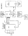
- Figure 1 is a block diagram illustrating a prior art call processing and messaging system.
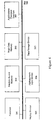
- FIG. 2 is a block diagram illustrating a call processing and messaging system as may be utilized by the preferred embodiment.
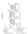
- Figure 3 is a block diagram of the internal architecture of the applications processor.
- Figure 4 illustrates a typical architecture of the configuration applications terminal of the present invention.
- FIGS 5 and 6 illustrate the linkage of tables of the applications processor.
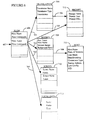
- Figure 7 is a flow chart illustrating a method of handling incoming calls as may be utilized by the preferred embodiment.
- Figures 8-10e are flow charts illustrating examples of call flow applications serviced by the preferred embodiment.
- the present invention is an integrated application controlled call processing and messaging system for controlling the processing of calls and messages received on incoming telephone lines.
- PBX personal area network
- the present invention anticipates the use of the disclosed application controlled call processing and messaging system with other telephone switching systems such as a key system, central office or Centrex system, or hybrid system.
- the methods for processing calls and messages described herein may be practiced in a system utilizing an external voice messaging system or may be equally practiced in a telephone switching system which provides the features of a voice messaging system as in integral function of the switching system.
- the methods for processing calls and messages described herein may be applied in a variety of systems in which the required call information may be obtained through the methods and apparatus detailed herein or through other methods and apparatus. It will be appreciated that the methods of processing calls and messages are not intended to be limited to use of the disclosed methods and apparatus for obtaining call information, except as specifically provided in the claims.
- trunk lines 101 connect with PBX 100.
- Individual telephone lines 151 are provided for direct connection of telephone handsets.
- Individual telephone lines 102 connect PBX 100 with a voice messaging system (VMS) 105.
- VMS voice messaging system
- One such voice messaging system is the Direct Access Link (D.I.A.L) manufactured by the assignee of the present invention.
- a voice message storage device 109 connects to voice messaging system 105.
- Control line 103 connects PBX 100 to VMS 105.
- Control line 103 provides VMS 105 with useable information regarding the source of the call.
- calls coming in on trunk lines 101 may be transferred to one of a plurality of telephones connected to telephone lines 151. If the telephone thus connected is busy or does not answer, the call may be forwarded to VMS 105 for further processing. Alternatively, calls coming in on trunk lines 101 may be transferred directly to the appropriate line of telephone lines 102. VMS 105 may thereafter handle the incoming telephone call using an automated attendant capability or a voice messaging or two-way voice messaging capability with a voice mailbox stored on voice message storage device 109.
- Storage device 109 contains a plurality of mailboxes each for storing a plurality of voice messages. In the prior art system, each mailbox stored on storage device 109 is associated with one of the extension numbers associated with telephone lines 151 or a predetermined party.
- PBX 100, VMS 105, and voice message storage 109 are prior art components as illustrated in Figures 1 and 2.
- the hardware components of the present invention include applications processor 110, an optional configuration applications terminal (CAT) 112, CAT data storage component 113, an optional host computer 106 and host data storage unit 107 as illustrated in Figure 2.
- applications processor 110 is a circuit board that is inserted into an available slot in VMS 105. It will be apparent to those skilled in the art that the applications processor 110 need not reside on a separate circuit board.
- an applications processor may be included as an internal component of a prior art call and message processing system.
- a prior art call and message processing system and associated operating system may also be modified to perform the application processing function of the present invention.
- the present invention is thus not limited to the specific architecture of the preferred embodiment.
- applications processor 110 includes a microprocessor CPU 120, random access memory (RAM) 121 and a disk storage device 122 for storing local data.
- Applications processor 110 also includes a VMS interface 123, host interface 124 and a CAT interface 125.
- VMS interface 123 is a high speed internal command link permitting command signals and events and status information to be transferred between VMS 105 and applications processor 110.
- host interface 124 is an IBM 3270 SNA/SDLC compatible interface. Such an interface protocol is well known in the art.
- Host interface 124 is optionally used for coupling applications processor 110 to a host computer in order to access external data residing thereon. It will be apparent to those of ordinary skill in the art that alternative interface protocols can be used for interfacing with a host computer.
- CAT interface 125 provides means for configuring the operation of applications processor 110 and for generating and modifying call flows.
- a personal computer is used as CAT 112 to which a disk storage device 113 is coupled.
- CAT interface 125 is an RS232 interface well known in the art.
- CAT interface 125 may be implemented using other interface protocols.
- alternative embodiments may use other than a personal computer for a configuration application terminal. For example, a standard ASCII data terminal may be used for this purpose. Once configured, the operation of the present invention does not require the connection of the CAT 112.
- the present invention integrates the messaging capabilities of the VMS 105 with the flexible control of a call flow processing language to provide a powerful call and message handling environment.
- the call flow language of the present invention is a programming language for specifying an application-specific sequence of events and operations in response to an incoming telephone call or system event.
- the call flow language allows a flow programmer to design and build custom applications incorporating various call and messaging features.
- the applications processor 110 uses the voice message handling and storage capabilities of VMS 105 while allowing the operation of VMS 105 to be directed under control of the applications processor 110 and the call flow language commands executing therein. It will be apparent to those skilled in the art that the scope of the present invention is not limited to an architecture using the voice message handling and storage capabilities of VMS 105. Equivalent alternative embodiments may be implemented where message handling and storage is controlled directly by the applications processor.
- call flows for various applications of an organization may be generated and stored for access by applications processor 110.
- Each flow is a script defining the operations for handling an incoming telephone call.
- incoming calls and associated messages are controlled by an application flow and not by a mailbox.
- more than one call flow can be used for handling a particular incoming call.
- a particular call flow can be used simultaneously by more than one incoming call.
- incoming telephone calls are received by VMS 105 on phone lines 102.
- the initial task of the present invention is to assign a call flow to a particular incoming call.
- the call is thereafter processed depending upon the command sequence coded in the particular call flow.
- incoming calls are assigned to a call flow using a set of system configuration tables residing in applications processor 110.
- VMS 105 can be configured to pass call control to applications processor 110 via interface 111.
- call control information is passed to applications processor 110 by VMS 105.
- This call control information includes, for example, the trunk number of the incoming call, the port number, extension number or the mailbox number associated with the incoming call, and in some cases, status information indicating a reason why the call was passed (i.e. the extension was busy).
- the VMS 105 may also pass to applications processor 110 the called party ID and/or the calling party ID number. Once the applications processor 110 receives the call information, the call is processed using information in the system configuration tables.
- applications processor 110 first checks a CALLID table 600 to determine the class of service (COS) to be assigned to the call. If VMS 105 passes a called party ID to applications processor 110, applications processor 110 searches CALLID table 600 for an entry that matches the called party ID number. If the applications processor 110 references CALLID table 600 and does not find an entry corresponding to the number associated with the call, the applications processor 110 references PORTS table 601. PORTS table 601 is used to determine the class of service (COS) to be assigned to the call where a called party ID is not available.
- COS class of service
- the applications processor selects one of a plurality of schedule tables 604, each corresponding to a particular COS.
- the specific schedule table 604 that is selected is based on day of week and time of day when the call is received. Each schedule can have as many as eight time periods in the preferred embodiment.
- the applications processor 110 uses the selected schedule table number to locate the information table number to be assigned to the call. Applications processor 110 then checks the information table 606 corresponding to the information table number to determine the name of the flow to be used to process the call.
- the information table 606 associates an information table number with a flow name, which is then assigned to the call. If the information table 606 does not contain a flow name corresponding to the call, a user error is logged.
- FIG. 608 illustrates the sequence of operations taken from the receipt of an incoming call to the execution of an associated call flow.
- additional application-specific tables are provided for handling an incoming call. These additional tables include: a HOST table, a PROMPT table, a SCREEN table, a SESSION table, a TRANSLATION table, a LOCAL DATA table, and a SYSTEM PARAMETER table.
- a particular application may not require all of the configuration tables listed above. In fact, a flow may not reference a table at all. For example, if a flow does not require a host application, the flow for the application does not reference the HOST table, SCREEN table, or the SESSION table.
- Figure 6 illustrates the linkage between the available configuration tables and commands within flow table 608.
- the HOST table 713 is used to describe how the applications processor communicates with the host computer to which it is optionally connected. There are two aspects to each HOST table entry: the physical link between the applications processor and the host, and the data link of the host connection.
- the physical link describes the characteristics of the connection between the host computer and the applications processor. This information consists of: host name, number of sessions, line mode, data encoding method, and connection type.
- Host name is the name assigned to the host connected to the applications processor.
- the number of sessions represents the total sessions configured in the SESSION table. Sessions are described in more detail below.
- Line mode specifies whether the data communications line 108 is operating in a full duplex or half duplex mode.
- the data encoding method refers to the way bits 0 and 1 are encoded.
- Connection type specifies whether the connection between the applications processor and the host is switched through a modem or non-switched through direct lines.
- each HOST table entry contains information about the data link level of the host connection.
- This portion of the HOST table entry describes the type of device being emulated by the applications processor.
- the data link portion of a HOST table entry describes the applications processor connection to a host computer.
- This portion of the HOST table entry contains the following information: station address, line configuration, and XID (exchange identification).
- the station address specifies origin and destination stations connected via the host computer data communications line.
- Line configuration specifies whether the data communications line is connected between two or more stations. For example, if one line connects two stations, the line configuration is set to a value of 2. If one line connects more than two stations, the line configuration is set to a value corresponding to a multipoint connection.
- XID is an acronym meaning exchange identification.
- XID consists of product identification and installation identification.
- the applications processor emulates an IBM 3274 cluster controller. The product identification in this case is 017.
- the PROMPT table 712 contains information about voice prompts.
- the PROMPT table includes prompt names and up to 128 characters of prompt text. When a call flow references a prompt name, the PROMPT table is used to find the voice mailbox where the prompt is stored.
- the SCREEN table 710 is used to identify each host application screen accessed by the applications processor.
- a host applications screen, or host screen is generated by the host computer.
- a host screen contains fields in which data is entered for processing or retrieving information associated with an incoming telephone call. Some of the fields on a host screen are used only by the host; others are used by both the applications processor and the host computer.
- Each SCREEN table entry corresponds to one host screen.
- the SCREEN table contains a list of field definitions for all the fields relevant to a particular application. Each screen table contains the following field definitions: field name, offset base, field offset, field length, protection level, and data type.
- the field name is a name assigned to a field in the host screen. This field name is used in call flows to specify the location for data entry or retrieval.
- Offset base is a parameter that specifies whether the field offset is absolute or relative to the cursor.
- Field offset is the exact location that specifies where the field starts.
- Field length specifies how many characters the field occupies.
- Protection level is a data item indicating when the data can be only retrieved (read only) or unprotected when the data can be entered retrieved or placed (read/write).
- the data type parameter is used to indicate whether the field is alphanumeric or numeric only.
- the SESSION table 708 is used to group host sessions into pools.
- a session is a logical connection between the applications processor and a host computer.
- a session links the application flow in the applications processor to the host computer.
- the applications processor accesses the host computer to get the information requested from the application call flow.
- a session pool contains all the sessions executing in a given application. By grouping the sessions into pools, multiple callers can simultaneously access an application while another group of callers can access a different application (on another pool).
- Pool name is a name used by the application flow to refer to the session pool. A flow can get a session from this pool.
- Host name is a name given to the host. This name must be the same as one defined in the HOST table.
- Session number range is the number of sessions allocated for a particular pool.
- logon fiow name is the name of the flow to be used when the applications processor first communicates with the host after a session power-on event.
- Clean-up flow name is the name of the flow used to bring up the first screen of a particular application, when a flow has freed the session explicitly, has reached an ENDFLOW statement or has exited abruptly.
- Idle flow name is the name of the flow used to prevent the session from logging off when no host access is performed for a period of time (idle time). Maximum idle time is the time range between which the idle flow is run.
- the TRANSLATION table 705 contains individual sets of translation items that are paired together to create a relationship in the form of a SEARCH-ITEM and a RETURN-ITEM.
- a translation refers to a single item in a TRANSLATION table, for example, a SEARCH-ITEM that translates into a RETURN-ITEM.
- SEARCH-ITEMs are used to find a corresponding RETURN-ITEM.
- RETURN-ITEMs are used to provide information to the caller. This information corresponds to the RETURN-ITEM configured to match a SEARCH-ITEM.
- the applications processor would use that entry to check the list of SEARCH-ITEMS configured in the TRANSLATION table. Once the item is found in the table, the applications processor can deliver to the caller the matching item (RETURN-ITEM) in a spoken form.
- the LOCAL DATA table 711 contains information about local databases. Each table entry serves as a definition of a data base, identifying the data base structure and type.
- a data base consists of a collection of records, each containing several fields of data.
- the data base is assigned a structure that describes the format of the individual records in the data base. This structure consists of group of field names. Optionally, one field name in the group can be assigned as the index field.
- Each local data base has a data base type that determines which flow commands can be used to access records. Additionally, the data base type identifies whether flows can modify records or simply retrieve records.
- the present invention provides at least three different data base types: look-up only, read/write, and sequential.
- the look-up only data base allows call flows to retrieve information only.
- the read/write data base allows flows to retrieve and modify information stored in existing records.
- the sequential data base allows flows to sequentially retrieve and modify information stored in existing records.
- a SYSTEM PARAMETER table contains values that pertain to all activities in the operation of the present invention. These activities can be categorized in five major areas: system specific, report generation, flow control, flow inputs, and flow conditions.
- System specific parameters include system name, system ID, and the default BAUD rate.
- Report generation parameters include the number of lines to be printed in each page of a report.
- Flow control parameters include the maximum duration of all flows.
- Flow input parameters set the format for inputting entries to be processes by the applications processor.
- Flow condition parameters specify the values for various time-out and error conditions encountered during the operation of the system.
- the preferred embodiment of the present invention uses the voice message handling and storage capabilities of VMS 105 while allowing VMS 105 to be directed under flow language command control. It will be apparent to those skilled in the art that the scope of the present invention is not limited to an architecture using the voice message handling and storage capabilities of VMS 105. Equivalent alternative embodiments may be implemented where message handling and storage is controlled directly by the applications processor.
- Voice messages manipulated by applications processor 110 are stored and identified using a message number.
- the message number for each message is retained by applications processor 110 for later access by a call flow.
- These message numbers are stored either in a host data base or in an applications processor local data base.
- the Call Flow Language is a collection of commands and statements used by the applications processor for handling an incoming telephone call and associated messages.
- call processing and messaging capabilities allow the development and customization of call processing and messaging applications. These call processing and message handling capabilities include call processing, voice messaging, interactive voice response, host data base access, call routing features, and local data base access.
- Application call flows are derived from the call flow programming language to develop and customize voice response applications.
- An application flow is the programming code based on the call flow language.
- a call flow is comprised of a series of statements that follow the call flow language syntax.
- the applications processor interprets and executes the call flows into usable applications.
- a particular application flow or program flow is made up of a series of flow statements to be performed in sequential order. Most statements start with a keyword that identifies the operation performed by the statement. Depending on the statement, the keyword is followed by additional information that must conform to the syntax or structure appropriate for the type of statement. All statements have a statement number associated with them. Statement numbers are generated by the system when the flow program is entered using. configuration applications terminal 112.
- a flow program consists of three sections: VARIABLES, DEFAULTS, and COMMANDS. Call flow statements are written and organized following the order of these sections.
- VARIABLES are items used for information storage and retrieval. VARIABLES are conveniently identifiable through the use of descriptive names that are assigned in the variable's section of a call flow. The current value of a variable can be changed during call flow execution. The value of a VARIABLE can be changed during flow execution by a CAPTURE, GET, INPUT, LET, or TRANSLATE command.
- the call flow language of the present invention also allows numeric and character constants to be used in call flow statements.
- the call flow language also makes direct use of some system configuration tables and application-specific tables. These tables are used to acquire information needed to process a call.
- the syntax of the statements in the VARIABLES section include the type of the variable being declared, the length of the variable (optional depending on the type of the variable), and the variable name. Each variable has an associated type.
- the types of variables supported by the present invention include: NUM, CHAR, and PROMPT.
- the NUM variable type is used to declare a variable used in arithmetic operations. If a NUM variable needs a decimal point, the number of significant digits to the right of the decimal point must be included in the length portion of the statement. If the number of decimal places is not specified, the variable is considered an integer. The number of decimal places specified determines the range of values that can be stored in the number.
- the CHAR variable type is used to declare a variable that contains text strings. When declaring a CHAR variable, a length value is required. A length value specifies the maximum length of any string stored in that variable. The maximum length allowed for any CHAR declaration is 132.
- CHAR variables may also be used to define dual tone multi-frequency (DTMF) variables. These character variables are used in the flow language to dial an extension. They are typically used with the CALL statement. DTMF characters can also be used to outpulse DTMF digits through the SPEAK statement. An example of this usage is DTMF signaling for potential networking applications. To use DTMF characters in a call flow, a variable must be declared as a CHAR variable, and then assigned a value using a command such LET or TRANSLATE.
- DTMF dual tone multi-frequency
- the PROMPT variable type is used to declare variables that contain a prompt identifier. Prompts are used to urge a caller to take a specified action or make a valid menu selection. Variables of type PROMPT can only be assigned by a TRANSLATE or LET command, and are then spoken using the SPEAK command. The PROMPT declaration does not require a length specifier.
- variable names may be made up of letters, digits, and underscore characters.
- the first character of a variable name must be a letter. No blank spaces are allowed within variable names.
- a variable name consists of a maximum of 16 characters. An error is generated if a variable name of more than 16 characters is declared.
- Dynamic variables may also be defined in a call flow statement.
- a dynamic variable contains dynamic run time data. The values in these variables are installation or call specific. The value of a dynamic variable can be assigned to a flow variable using the LET command.
- Dynamic variables are uniquely identified by a two character type prefix, a dollar sign, and the identifier which describes the variable.
- the five types of dynamic variables provided by the preferred embodiment include: a system variable, a call variable, a host specific variable, local data variable, and flow specific variable. Dynamic system variables are used to reference system-wide values required by a call flow.
- Dynamic call variables give specific information about the currently executing call flow. These variables include information such as the original called party ID, the original calling party ID, a caller digit entered on a menu, or the port currently being used by the current call.
- an incoming call can be classified into four different types: an internal direct, internal forwarded, external direct, and external forwarded call.
- An internal direct call is a call placed from an internal extension directly to the VMS.
- An internal forwarded call is a call placed from an internal extension to another extension forwarded by VMS on a busy, RNA condition, etc.
- An external direct call is a call from an external trunk that the PBX connected directly to the VMS.
- An external forwarded call is a call from an external trunk to an internal extension that forwarded to the VMS on a busy, RNA condition, etc.
- a host specific dynamic variable gives specific information about the current host session assigned to the flow. These dynamic variables are used to retrieve the current host session number. Flow specific variables give information about the currently executing flow. This information includes the flow execution time in seconds and the flow status from the last statement executed. Local data base dynamic variables are used to obtain the current value of the current record number in use by a call flow.
- the DEFAULTS section of a flow program is used to specify default handlers for conditions that could occur within a call flow. For example, if a caller is prompted with a menu of choices and asked to make a selection by entering a number using the DTMF keypad, the input can time out if no selection is made. If the timeout occurs several consecutive times, a timeout limit condition is set. Using the DEFAULTS section of the present invention, default handling of other system error conditions may be specified.
- the COMMANDS section which is the body of the flow program, contains the actual flow statements that control how a call is handled. Statements are executed sequentially unless a GOTO or GOSUB statement transfers control to a different place in the program, or a condition transfers execution to a default handler.
- the body of a flow program begins with the first executable statement. All statements in the COMMANDS section are considered part of the body of the program. Execution of a flow terminates whenever an end flow statement is encountered.
- the following section describes each of the commands provided by the call flow language of the present invention. The syntax of each command and specific examples of the use of each command is also provided.
- the CALL statement places a call to the number specified.
- the port to be used is automatically assigned as the next idle VMS port that is configured for outcall.
- the call statement is valid only if the flow is not already connected to a port.
- CALL puts the flow on a port in connected mode.
- variable ⁇ charvar> contains more than 8 digits, it is assumed to be an external call. If the variable specified contains a valid VMS mailbox, the mailbox extension is called. Otherwise, the extension number contained in the variable specified is called. The extension number must contain valid DTMF characters.
- the CAPTURE statement retrieves data from a host screen that has been previously received using the HOSTRCV command.
- the syntax for the CAPTURE command is as follows: CAPTURE ⁇ charvar> AT ⁇ field> ON ⁇ screen>.
- CAPTURE retrieves the contents of a field on a host screen and then assigns it to a CHAR variable defined in the VARIABLES section.
- the screen refers to a screen name previously defined in the SCREEN Table.
- the field must be the name of a filed previously defined in that specific screen entry.
- CONNECT statement is used to complete a successful transfer of a call to a mailbox or extension. (See TRANSFER command)
- the syntax for the CONNECT command is as follows: CONNECT
- the DESELECT statement is used to release current access to a local database.
- a SELECTed database must be DESELECTed before a flow can successfully execute a GOFLOW statement.
- a local database is implicitly deselected whenever a flow is terminated.
- the EDIT statement is used to remove characters and substrings from character strings that are stored in CHAR variables during flow execution.
- the ENDFLOW statement completes the processing of a flow. It performs an implicit HANGUP of the VMS port associated with the flow.
- the keyword CONDITION can be added to an ENDFLOW statement to report the reason for a flow's termination, according to the last condition set in the flow.
- the ENDSUB statement terminates the subroutine and directs the flow to exit from a subroutine. Execution continues at the statement immediately following the GOSUB that called the subroutine. (Also see RETURN). It is the last statement in a subroutine. Each subroutine must have exactly on ENDSUB statement.
- the ERASE statement erases a previously recorded message.
- the message is a variable declared of type NUM:0 that has a message value set up by a previous RECORD command.
- the FIND statement searches for an item using a TRANSLATION Table, or searches for an item in a LOCAL DATA Table.
- This keyword reserves an uninitialized record at the end of the current sequential database (SEQ). After a FIND NEW statement, the only allowable statements using the local database are PUT followed by a WRITEDB. A record number is assigned after the WRITEDB statement is executed. This record number is stored in the dynamic variable DB$RECORDNUM.
- This keyword searches the database specified by index, and matches the first record with the specified search condition.
- the database must also have an index defined.
- This keyword operates similarly to FIND FIRST, except that it searches for the database starting from the current record rather than searching from the beginning of the database.
- the database must also have an index defined.
- This keyword accesses a specific record specified by the record number.
- the record number is specified through the use of an integer variable or constant. This type of access is allowed on all types of databases.
- the FREESESSION statement frees the host session currently held by the flow. If the SESSION TABLE has a Cleanup Flow associated with the pool to which this session belongs, then the Cleanup flow is run on this session in the BACKGROUND mode.
- the session is reset after freeing it. This option should be chosen if the session is in an unknown state and the flow program is not able to bring it to a known state. After a reset is complete, the session will go through the normal logon procedures and will eventually be brought to a known state. If the SESSION Table has a Logon flow associated with the session, it is run on the session in the BACKGROUND mode.
- This command retrieves data from an array, or from a local database record.
- the syntax for the GET command is as follows:
- the GETSESSION statement allocates a host session to a flow from a specified session pool.
- the syntax for the GETSESSION command is as follows: GETSESSION ⁇ session pool>
- the GODIAL statement gives control of the call to VMS.
- the caller will be treated as a new caller who has entered the mailbox specified as a CHAR variable.
- the CHAR variable must contain valid DTMF digits. If the first digit of the CHAR variable contains a '#', the caller proceeds through the normal mailbox logon sequence.
- the GOFLOW statement completes the processing of the flow that is currently being executed an begins the processing of the flow specified.
- the GOSUB statement directs the flow to execute the subroutine specified. When the subroutine is completed, it returns and continues at the statement immediately following the GOSUB.
- GOSUB command follows: GOSUB INITIALIZE
- the GOTO statement transfers control of the flow program to another section of the program specified by a label.
- the HANGUP statement hangs up the VMS port associated with a particular call, freeing it to handle other calls. The flow will continue until an ENDFLOW statement is executed.
- HANGUP The syntax and an example of the HANGUP command is as follows: HANGUP
- the HOSTRCV statement waits for a screen of data from the host computer.
- HOSTRCV The syntax for the HOSTRCV command is as follows: HOSTRCV
- the HOSTSND statement sends a screen of data to a host computer.
- Aid is an attention identifier terminal key sent to the host to request an action.
- the specific aid to be used is the same key that the terminal operator would press to perform the function and is dependent upon the host application.
- ENTER is the default key that is used if one is not specified. The valid keys are: Aid Key Function ENTER Processes the screen. (Send the ENTER key). CLEAR Send the CLEAR key ATTN Send the ATTN key PF1 through PF24 Programmable function keys. (application dependent) PA1 through PA3 Programmable function keys. (application dependent)
- the IF statement compares two variables or compares a variable with a constant.
- the comparison operators allowed are:
- the IF statement is immediately followed by a THEN GOTO label statement.
- the flow will transfer to the label if the comparison is accurate.
- variable or constants in the comparison must be of the same type.
- ASCII values of the first characters that differ in the variables are used in the comparison.
- the shorter string is considered less than ( ⁇ ) the longer string.
- the INPUT statement accepts DTMF input from the person who is currently connected to the flow.
- the input can be placed in either a NUM or CHAR variable.
- the command reads numeric input from the DTMF keypad and places it in the NUM variable, verifying that the value is in the specified range.
- the second command is for inputting data into a CHAR variable, checking to assure that the length of the string entered is valid.
- system configuration parameters that can be set that affect how INPUT is handled. These include:
- VISANUM is declared as a CHAR variable because it is too large to store as a NUM variable.
- the LET statement assigns a new value to a variable.
- the value assigned can be:
- LET assigns a value to either a CHAR variable, a NUM variable, or a PROMPT variable.
- the MENU statement branches to a choice of labels based on the caller's single-digit input.
- the MENU statement includes all of the following ON statements as part of the MENU. If there is no corresponding ON statements for the character input, or the user entered invalid input, the flow continues sequentially with the following statement, which is the GOTO TRYAGAIN in the example below.
- the ON statement handles conditions that can occur during execution of a flow. It is also used to check for a specific DTMF digit as part of the MENU command.
- Syntax statements 1 and 2 show the syntax after a MENU command.
- the characters A, B, C, D refer to DTMF tones, and not to keys on the phone. Brackets [] are required to surround the menu choices in this usage of the ON command.
- Syntax statements 3 and 4 show the usage of ON to handle a condition. The syntax in statement 4 is used only in the COMMANDS section of flow; it cannot be used in the DEFAULTS section.
- the PLACE statement places the contents of a variable onto a host screen.
- PLACE puts the value of a CHAR variable or constant onto a screen field.
- the screen and the field in which to place the variable are identified by their names as specified in the SCREEN Table.
- This command places data in arrays or into a local database record.
- the index value must be:
- the index value can be a variable or an integer constant. In either case, the index must be a positive non-zero value that is less than or equal to the maximum number of elements declared for the array. If ⁇ index> is a variable, it must be declared as a NUM:0.
- the flow variable and the field used in the PUT statement must be of the same declared type.
- PUT places the contents of the flow variable into the specified field using the currently selected record of the database.
- a database record is selected for access using the FIND command.
- An error occurs if no record is selected when PUT is executed.
- PUT places the variable into the database record, but the database is not updated until the record is written onto disk using the WRITEDB command.
- a PUT operation to an index field is not allowed.
- ⁇ numvar> is the message ID and is a variable of type NUM:0.
- the ⁇ message id> is returned for subsequent use, after the statement is executed.
- subsequent RECORD NEW statements are illegal until the message is explicitly saved or erased using SAVE or ERASE. No other prompt can access the message until a SAVE statement is executed. If a new message is outstanding at ENDFLOW, it is automatically erased, and an error is logged.
- ⁇ numvar> is the message ID of type NUM:0 and must have been previously used in a RECORD NEW statement.
- This message identifier can be used in ERASE, SPEAK, SEND, and SAVE statements. The message is recorded at the end of the existing message specified by the message ID. All messaging access by other channels to this message is locked out while RECORD...APPEND is in progress.
- the RETURN statement directs the flow to exit from the subroutine and to continue execution at the statement immediately following the GOSUB that called the subroutine.
- An ENDSUB statement does an implicit RETURN.
- RETURN RETURN
- RETURN RETURN
- the SAVE statement allows a message created with RECORD NEW to be stored internally for access by a subsequent flow. After a RECORD NEW statement, the message created is considered "open.” The message must be saved or erased (by using the SAVE or ERASE command) before the end of the flow. Otherwise, the message is automatically erased and a User Error is logged. The SAVE statement is valid only once for the message created by the RECORD NEW statement within the flow. In order for other flows to access a message, the following two steps are necessary:
- ⁇ numvar> is the message ID of the variable type NUM:0 that must have been previously used in a RECORD statement. This message identifier can be used in ERASE, SPEAK, SEND, and SAVE statements.
- SAVE CUSTMSG SAVE CUSTMSG
- the SELECT statement is used to gain access into a local database.
- a database must be SELECTed before an FIND, GET, or PUT commands are introduced in the flow program.
- ⁇ database> must be the name of a database defined in the Local Data Table
- This command sends a message to a destination mailbox.
- the message is marked as having been sent by the creator mailbox, allowing a reply or error message to automatically return to the creator as specified. If no creator is specified, the creator defaults to the error mailbox configured on VMS.
- the destination mailbox can be a network address. Unless explicitly ERASEd, the message remains available after SEND is executed.
- ⁇ numvar> is the message ID and is a variable declared NUM:0 that has a message identifier set up by a previous RECORD command.
- the destination mailbox for the message must be specified as a CHAR variable. If the optional creator mailbox is specified, a reply or failure is directed to the creator mailbox. Otherwise, the system error mailbox specified on VMS is used as the default creator.
- the creator mailbox must be specified as a CHAR variable.
- the SPEAK statement relays information to the person connected to the flow.
- SPEAK is used to output a variable or a prompt to the caller or agent.
- a variable may be spoken in a variety of speaktypes which are described below. If no speaktype qualifier is specified, a default is chosen based upon the type of the variable.
- STARTSUB is the first statement in a subroutine. It identifies the subroutine's name. Each subroutine must have one STARTSUB statement.
- Name identifies the subroutine's name.
- the TRANSFER statement puts the current caller on hold and calls the mailbox or extension specified. Call progress is monitored. If TRANSFER succeeds, the CONNECT statement is required to complete the transfer. Either the standard or alternate transfer codes are selected, based on the INFORMATION Table used. The INFORMATION Table corresponds to the mailbox or to the port if the variable specified does not contain a valid mailbox.
- variable specified contains a valid VMS mailbox
- the mailbox extension is used. Otherwise, the extension number contained in the variable specified is used.
- the extension number must contain valid DTMF characters.
- the TRANSLATE statement is used to convert one data value to another using a TRANSLATION Table.
- a previously defined TRANSLATION Table is searched to see if it contains the particular statement's value in a variable. If so, the table entry for that variable is assigned to a new variable.
- TRANSLATE The syntax for the TRANSLATE command is as follows: TRANSLATE ⁇ search_var> TO ⁇ retum_var> USING ⁇ tablename>
- the first variable contains the data that will be translated to a new value and placed in the second variable based upon the contents of the table specified by the tablename.
- the search and return variables must match their corresponding types in the specified table.
- Table name must be previously defined in the TRANSLATION Table using the configuration applications terminal software.
- the WAIT statement delays execution of the flow program until the number of specified second has elapsed.
- the maximum time is 65535 seconds.
- Numeric is either a NUM:0 variable or a constant that specifies the number of seconds to delay before reactivating the flow program.
- the WRITEDB statement is used to output the currently selected record to the local database file and then returns the written record number.
- the syntax for the WRITEDB command is as follows: ⁇ WRITEDB ⁇ numvar> ⁇ database>
- the flow no longer has a selected record for the database and must do another FIND before any PUT or GET commands can be executed.
- the record number for the record just written is returned in an integer variable ⁇ numvar> specified in the WRITEDB command. This variable must be a NUM:0 variable.
- the Configuration Applications Terminal (CAT) 112 is a computer used to configure the operation of the applications processor 110 and its associated call flows.
- the CAT 112 has several functions: 1) to perform terminal emulation for communication with the applications processor 110, 2) to backup and restore system configuration tables and application-specific tables, 3) to backup and restore local databases, 4) to to transfer a call flow program for off-line editing, and 5) to update applications processor system software.
- a typical architecture of the configuration applications terminal 112 is shown in Figure 4.
- Terminal emulation allows the CAT to communicate with applications processor 110 directly through a cabled connection or remotely through a modem. Characters typed on the CAT keyboard are sent to applications processor 110, and information from applications processor 110 is displayed on the CAT monitor. The only time the CAT is not performing terminal emulation is when menus are displayed. At this time, communication with applications processor 110 is temporarily suspended because the menus control the terminal.
- the CAT uses a packet-based, error-correcting data transfer protocol at speeds up to 19200 baud to pass information between applications processor 110 and the CAT. Data transfer is initiated by menu selection and is performed by software residing in the CAT.
- This CAT software includes a Backup function, a Restore function and an Update function.
- the Backup function transfers data from applications processor 110 to the CAT hard disk drive 113.
- the Restore and Update options transfer data from the CAT hard disk drive 113 to Applications processor 110.
- the CAT software also includes utilities to manage individual applications processor system configurations.
- System configurations including the content of system configuration tables and application-specific tables, can be added, deleted, and modified. Backed-up system configurations can be archived to and recovered from a floppy diskette.
- the CAT software also includes utilities to manage log files, which capture communication sessions from applications processor 110. Multiple log files can be stored, displayed printed, and deleted for each applications processor 110 system configuration defined within the CAT software.
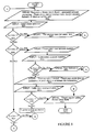
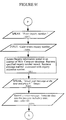
- FIG. 8 a sample application processing flow chart is illustrated.
- the application processing flow illustrated in Figure 8 represents a flow program activated and executed by applications processor 110 in response to an incoming telephone call received from VMS 105 in the manner described above.
- processing flow begins at bubble 901. Initially, an announcement message is audibly transmitted to the caller using the SPEAK command of the call flow language (processing box 902).
- Hardware means for recording and playing back audible speech is an apparatus well known in the art.
- the announcement message spoken or transmitted to the caller in processing box 902 includes a menu of options provided for the caller and a prompt for the operator to enter one of the options provided. Options are entered by a caller using the numeric keypad buttons on the telephone handset. These buttons generate dual tone multi-frequency (DTMF) signals which can be used to distinguished the various options entered by a caller. The technique of using DTMF signals is well known in the art.
- DTMF dual tone multi-frequency
- processing path 905 is taken to processing box 907. Since the entry of a 1 key is associated with a request for interest rates in the example of Figure 8, another SPEAK command is executed to announce the current interest rates as retrieved from an internal database using the SELECT, FIND and GET commands. Once the SPEAK command is executed in processing box 907, processing flow continues at the bubble labeled A where the announcement message, the menu and prompt are again spoken in processing box 902.
- the example of Figure 8 processes a request for an account balance.
- the caller is prompted to enter his account number (processing box 911) the caller enters the account number using the telephone keypad.
- An INPUT command is executed to retrieve the account number entered by the caller (processing box 912).
- the account number is validated in decision box 913.
- the caller-entered account number may be invalid for several reasons. First, an inappropriate quantity of numbers may have been entered. Secondly, the entered account number is used with a FIND command in order to access a database containing valid account numbers.
- the account number is rendered invalid.
- a message is spoken to the caller stating that the account is invalid and prompting the caller to enter a selection corresponding to a subsequent action to be taken (processing box 917).
- An INPUT command is then executed to retrieve the selection made by the caller for an invalid account number (processing box 918). If the user enters a 3 key (decision box 919), a termination message is spoken to the caller (decision box 922), and the call flow processing logic of Figure 8 is terminated at termination box 924.
- the call is transferred to a live personal representative at processing box 923 where the call is handled manually and without further control by the call flow logic of Figure 8.
- the call is transferred to live assistance in processing box 923 by execution of the TRANSFER command and the CONNECT command.
- processing path 914 If at decision box 913 a valid account number is entered (processing path 914), another SPEAK command is executed to audibly convey to the caller the current balance of the account number entered earlier (processing box 916).
- the account balance is retrieved from an account database using the SELECT, FIND, and GET commands. Once the account balance is spoken to the caller at processing box 916, processing loops back to processing box 902 through the bubble labeled A in Figure 8.
- processing path 910 is taken to decision box 925. If the caller enters the 3 key (processing path 926), processing control is transferred to the bubble labeled B where the call is terminated with a termination message (processing box 922). If the 3 key is not depressed or a timeout occurs, processing again transfers to the bubble labeled A as shown in Figure 8.
- processing path 926 If the caller enters the 3 key (processing path 926), processing control is transferred to the bubble labeled B where the call is terminated with a termination message (processing box 922). If the 3 key is not depressed or a timeout occurs, processing again transfers to the bubble labeled A as shown in Figure 8.
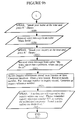
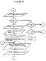
- Figures 9a through 9f illustrate the call flow processing logic for handling service calls made to a help desk.
- callers with problems or questions call a general help number in order to resolve their questions.
- the present invention serves to facilitate fast and effective communication between callers with problems and the specialists who can help them.
- the present invention automatically manages and tracks information about the problems presented by the callers and the results or answers provided to them by organization specialists.
- prior art systems are unable to effectively handle the wide array of caller problems and questions placed to a single help line telephone number.
- the help desk application is efficiently automated as illustrated by the logic in Figures 9a through 9f.
- processing begins at bubble 1001.
- applications processor 110 determines that the called ID is that of the help desk (processing box 1002).
- SPEAK command an initial announcement message, a menu of options, and a prompt message is spoken to the caller (processing box 1003).
- the caller selection is then received (processing box 1004) using the INPUT command.
- processing path 1007 is taken to processing box 1008.
- key 1 is associated with a request by the caller to record an inquiry for the help desk. If the caller enters key 2, processing path 1066 is taken to the bubble labeled P illustrated in Figure 9f. in this second example, key 2 is associated with a request by the caller to update an inquiry already existing from a previous transaction with the help desk. If the caller enters key 3 on the telephone keypad, processing path 1069 is taken to the bubble labeled N illustrated in Figure 9e. In this second example, key 3 is associated with a request by the caller to check on a response to a previous inquiry made to the help desk. If the zero key is entered by the caller, processing path 1073 is taken to processing box 1074 where the call is transferred to a live representative for further manual call processing. If a key other than keys 0 through 3 is entered or if a timeout occurs, processing path 1072 is taken to the bubble labeled K illustrated in Figure 9a where the initial announcement message, menu and prompt messages are repeated (processing box 1003).
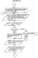
- processing box 1008 handles a caller request for recording a new inquiry for the help desk.
- an inquiry database is accessed using the SELECT command.
- a new record is opened in the inquiry database using the FIND NEW construct of the FIND command.
- a PUT command followed by a WRITEDB command is used to initialize the new record and to produce a record number associated with the new record (processing box 1008).
- the SPEAK command is used to prompt the caller to enter a seven digit telephone number (processing box 1016).
- the INPUT command is then used to retrieve the telephone number entered by the caller (processing box 1017).
- processing box 1018 a new voice message is created for recording an inquiry by the caller.
- the RECORD NEW command construct of the call flow language can be used for this purpose. Information such as time, date, caller telephone number, etc. can be integrated or recorded into the new message using the RECORD command.
- the RECORD command returns a message number associated with the new message for use in later call flow processing. Processing then continues at the bubble labeled L in Figure 9b.
- call flow processing for a help desk application of the second example continues.
- the SPEAK command is used to prompt the caller to speak his/her name for recording into the new message (processing box 1019).
- the name of the caller is recorded into the new message at processing box 1020.
- the SPEAK command is again used to prompt the operator to enter his/her inquiry at the tone and to terminate his/her inquiry by pressing the pound (#) key (processing box 1022).
- the RECORD command is again used to receive a voice message from the caller, the content of which represents his/her inquiry to the help desk (processing box 1023).
- a technician database is accessed using the SELECT and FIND commands.
- a new record in the technician database is opened using the FIND NEW command construct.
- the message number associated with the message used to receive the caller's name and inquiry is posted to the new record in the technician database using the PUT command.
- a unique inquiry reference number associated with the caller's inquiry is generated and put into the technician database along with the associated message number (processing box 1021).
- RECORD command a new message is generated which integrates the inquiry reference number into a termination message to the caller (processing box 1024). Call flow processing for the new inquiry then terminates at termination box 1025.
- an inquiry update request is specified if a caller depresses key 2 of the telephone keypad (processing path 1066).
- call flow processing passes to the bubble labeled P as illustrated in Figure 9f.
- call flow processing for updating an existing inquiry is illustrated.
- the SPEAK command is used to prompt the caller to enter the existing inquiry number (processing box 1057).
- the INPUT command is used to retrieve the inquiry number entered by the caller (processing box 1058).
- the inquiry database is accessed using the SELECT command and the FIND command.
- the inquiry message number associated with the inquiry reference number entered by the caller is retrieved (processing box 1061).
- the SPEAK is then used to prompt the caller to enter the inquiry update (processing box 1060).
- the RECORD command is used to record the update to the inquiry (processing box 1059).
- the RECORD APPEND command construct can be used to append a new message onto an existing message.
- data such as time, date, and caller ID can be integrated into the message.
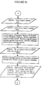
- processing path 1069 is taken to the bubble labeled N illustrated in Figure 9e.
- processing in response to an operator request to check on a response to a previous inquiry is illustrated.
- the SPEAK command is used to prompt the caller to enter the inquiry number (processing box 1051).
- the INPUT command is used to retrieve the inquiry number entered by the caller (processing box 1052).
- the inquiry database is then accessed. Using the inquiry number entered by the caller, the inquiry record associated with the inquiry is retrieved. Similarly, the message number associated with the original inquiry message is retrieved (processing box 1053).
- the original inquiry message is spoken to the caller using the SPEAK command (processing box 1054).
- the message number of the technician's response to the original inquiry message is retrieved from the inquiry record in the inquiry database (processing box 1055).
- the technician's response is spoken to the caller using the SPEAK command (processing box 1056).
- Current information such as date and time can also be integrated into the message.
- Call flow processing then is transferred back to the bubble labeled K illustrated in Figure 9a where the initial announcement message, menu of command selections, and prompt is spoken to the caller.
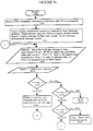
- FIGS 9c and 9d A related call flow for the help line application is illustrated in Figures 9c and 9d.
- Figures 9c and 9d illustrate call flow processing for a call received by a technician placing an incoming call on a line dedicated to technicians or specialists servicing callers making inquiries to the help line. This call flow is initiated in a matter similar to that described earlier.
- a call flow is illustrated for an incoming call received by the call processing and messaging system from a technician or specialist servicing inquiries to a help line.
- processing starts at the bubble labeled 1030.
- the applications processor identifies the caller ID as a technician (processing box 1031).
- the inquiry database is accessed using the SELECT command the FIND command.
- the inquiry database is searched for new inquiries. If a new inquiry is found, the message number associated with the new inquiry is retrieved from the database (processing box 1032).
- the inquiry found in the inquiry database is spoken to the technician (processing box 1033).
- the name of the caller making the inquiry, the time of day and the date is incorporated into the message spoken to the technician. Having spoken the inquiry to the technician, the technician is prompted to enter a selection corresponding to the desired action to be subsequently taken. In the example presented in Figure 9c, the technician is prompted to press a I to reply to the inquiry and forward the reply now, to press 2 to reply to the message later, or to press 3 to speak directly to the caller making the inquiry.
- the INPUT command is used to receive the selection made by the caller (processing box 1034). If the technician enters the 1 key (processing path 1037), a reply to the inquiry is processed immediately starting at processing box 1044.
- the call flow terminates at termination box 1041. If the technician enters the 3 key (processing path 1070), the applications processor dials the telephone number entered by the caller when the original inquiry was recorded (processing box 1043). The call is placed using the CALL command provided by the call flow language of the present invention. Once the call is placed, subsequent automatic call flow processing is pre-empted. If the technician does not enter a 1, 2, or 3 key or a timeout occurs on the entry of one of the keys, processing transfers to the bubble labeled J illustrated in Figure 9c. At bubble J in Figure 9c, the technician is again prompted to enter a selection.
- the calling technician has chosen to reply to the new inquiry and to forward his response immediately.
- RECORD NEW command construct a new voice message is created for storing the technician's response to the inquiry. Additional information such as date and time are also integrated into the message (processing box 1044). Processing for the call flow then is transferred to the bubble labeled M illustrated starting in Figure 9d.
- the SPEAK command is used to prompt the technician to speak his response to the inquiry made by the original help desk caller (processing box 1045).
- the voice response spoken by the technician is received and stored in the new message (processing box 1046).
- FIG. 10a through 10e A third example of the operation of the present invention is illustrated in Figures 10a through 10e.
- the call flow illustrated in Figures 10a through 10e implements a streamlined order entry and tracking system using the applications hardware and call flow processing logic of the present invention.
- the call flow language commands are used for processing and order entry call at each step in the application.
- various databases of information are accessed and updated as the call is being serviced.
- the present invention provides a flexible and dynamic call processing and messaging system providing seamless access to data and voice messages.
Abstract
Description
- The present invention relates to the field of call processing and messaging systems. Specifically, the present invention relates to call processing and voice messaging systems for a telephone network.
- An important aspect of most any business or organization's daily operations is the ability to handle incoming telephone calls in an efficient and timely manner. One well known way to handle a multitude of incoming telephone lines is the use of a private branch exchange (PBX) or central exchange (Centrex). A PBX or Centrex is a telephone exchange system serving an organization, which may be coupled with multiple incoming and outgoing trunk lines and multiple telephone sets at the organization's premises. PBX or Centrex systems provide a variety of functions such as switching of calls from the incoming trunk lines to any of the extensions, switching calls between two extensions, and switching calls between extensions and outgoing trunk lines. Numerous PBX and Centrex systems are well known and commercially available.
- A number of call processing and voice messaging systems are known in the art and are commercially available which may be coupled with a PBX or Centrex and used to automate the answering of incoming calls from the outside telephone network and the taking of messages when the extensions are not answered by the called parties. Such voice messaging systems incorporate features such as the recording of voice messages for users in what are known as user's "mailboxes". Such voice messaging systems may be accessed by users calling from PBX extensions or from the telephone network over incoming trunks.
- These prior systems can be categorized into four main types of systems: 1) call processing systems sometimes called automated attendant systems for directing incoming calls to an extension, 2) call processing systems usually called voice messaging sustems for handling a call that does not complete connection to an extension, 3) two-way voice messaging systems or voice store and forward systems for speaking messages to a caller from fixed address mailboxes, and 4) interactive voice response systems for retrieving data from a database of information in response to a caller request and speaking messages to a caller.
- In the first category of prior art systems, the automated attendant system answers incoming trunk calls by instructing the PBX or Centrex to direct the incoming calls to a group of extensions. Voice ports of the system are coupled with this group of extensions and appear to the PBX or Centrex simply as single line telephone sets. Typically, the automated attendant system will answer a call directed to it and provide a prerecorded voice message asking the caller to enter the extension number to which he/she desires to be connected. Depending on the specific automated attendant system, the caller may be offered the option of being transferred to a PBX or Centrex attendant. Examples of such automated attendant systems include Dytel, Inc. and a call processing and voice messaging system called Direct Access Link (D.I.A.L) manufactured by the assignee of the present invention.
- In the second category of prior art systems, an important voice messaging function is included for the handling of calls which do not successfully complete connection to the originally intended extension (the extension was busy, did not answer, or had been intentionally places in a mode in which it was not accepting calls). Such a function may be accomplished in known voice messaging systems by instructing the PBX or Centrex to forward all such unanswered calls to a group of extensions coupled with the voice ports of the voice messaging system. The voice messaging system may then answer the uncompleted calls. Various methods are known in the art whereby the PBX or Centrex systems provide information to the voice messaging system regarding the identification of the caller and the called party. See U.S. Patent No. 4,926,462, Ladd et al. Depending on the specific voice messaging system, the caller may be allowed to leave a voice message or call another extension. Known prior art systems of this kind include a call processing system manufactured by Digital Sound, Inc., Octel, Inc., AT&T, Inc. and a call processing and voice messaging system called Direct Access Link (D.I.A.L) manufactured by the assignee of the present invention.
- The third category of prior art systems include two-way voice messaging systems for storing and forwarding voice messages from preassigned fixed mailbox addresses between users of such systems. Each user of such a two-way voice messaging system is assigned a "voice mailbox" which he/she uses to record and send messages to other users and to listen to messages received from other users. These fixed mailbox addresses are typically configured and installed in the voice messaging system when a new "user" is added to the system. Such a prior art system is disclosed in U.S. Patent No. 4,602,129, Matthews et al.
- The fourth category of prior systems include interactive voice response systems for retrieving data from a database of information in response to a caller request. The retrieved data is then converted to audible form and spoken as a message to a caller. For example, a prior art system may be used by a caller to audibly receive the balance in a bank account. These interactive voice response systems are typically limited to a specific set of applications where transactions between a caller and the system are highly predictable. Such an interactive voice response system is manufactured by Intervoice Inc. of Dallas, Texas.
- Several problems have arisen with these prior art approaches for a call processing, voice messaging, or interactive voice response system. The main drawback with prior art call processing and messaging systems is a lack of flexibility, or in the case of an interactive voice response system, the inability to design applications which take advantage of the capabilities of a call processing and messaging system. Such systems are limited in their ability to be customized for the various applications in which a call processing and messaging system might be used. For example, the prior art automated attendant systems can be improved to provide a means for directing a call to different extensions depending upon many application and caller-specific conditions. Such conditions include, for example, the identity of the caller, account status of the caller, and a variety of other conditions specific to a particular application. If calls to a desired extension are not completed, stored application-related voice information such as customer-specific instructions can be spoken to the called party. Prior art systems are unsuited to the unpredictable and variant needs of these diverse call processing applications.
- It is often convenient for an organization to have a single incoming telephone number used for general customer assistance or general information. It would be desirable to provide more flexibility in handling such calls. In prior art systems, incoming calls to such a general information telephone number would be routed to the fixed address associated with the telephone line which could be routed to one available (i.e. not busy) called party of a group of called parties. Thus, a fixed mailbox for each called party in the group of called parties would be used to inconveniently store messages for a general assistance line. Callers using prior art systems and the organization receiving incoming telephone calls are not able to communicate in an application-specific, individualized, and efficient manner. Such systems can be improved by allowing any message to be routed to any available mailbox. Prior art systems often require intervention by a live operator in order to properly handle incoming telephone calls. In addition, applications using prior art systems are often slaved to the capabilities provided by the system and not to the needs of the particular application.
- Prior art interactive voice response systems are not flexible enough to respond in various ways to the content of information retrieved from a database in a particular application. Such systems can be improved by incorporating processing logic into the system for tailored handling of the vast number of different cases and situations presented by a database of information in many diverse applications. In addition, as situations or conditions change, prior art systems can be improved by allowing call and message processing logic modification without disrupting normal operation of the system.
- It is therefore an object of the present invention to provide a call processing and messaging system that integrates PBX or Centrex call information with application-specific and database information to create a more flexible and adaptable system customized to the needs of a panicular application using the call processing and messaging system. It is a further object of the present invention to provide a call processing and messaging system that may handle calls differently depending on the source of the call. It is a further object of the present invention to provide a call processing and messaging system that does not require a fixed mailbox address to be associated with calling or called parties. It is a further object of the present invention to provide a call processing and messaging system that uses customized logic to handle incoming calls and messages. It is a further object of the present invention to provide a call processing and messaging system that allows customized call processing and messaging logic to be modified while the system is still operating.
- Prior art document GB-A-2 225 916 discloses a voice messaging apparatus. In response to a received message the apparatus allocates a temporary mail box to enable any reply to a message to be left. The apparatus provides a caller with an address such as a telephone number or a password to enable the caller to access that temporary mail box at a later time. When the user of the messaging apparatus retrieves the initial message, he is alerted by the messaging apparatus to the fact that a storage location has been allocated to the caller. The user can then respond by recording a reply to the initial message in the allocated temporary mail box. The subsequent access by the original caller of that location enables the caller to hear the reply.
- WO-A-87/00375 discloses that during the course of a telephonic communication, a computer formulates identification data for the caller which includes the chronological sequence of the call, the assigned designation of the call, and a set of acknowledgement digits for the call. Such data identification is registered in a specific storage section. Moreover, the acknowledgement digits may be related to the call record sequence. The computer fetches the call record sequence number, assigns a designation and encodes the sequence number as the acknowledgement digits. Then the computer queues the voice generator to provide information to the caller.
- US-A-4,759,056 discloses a personal-servicing communication system which requires a portable memory device in which personal information is stored and which renders the service available to the person in accordance with the information stored on that memory device upon having read the information on the memory device. This prior art system is provided with a mail system, which is unlocked by a password. Moreover, on the portable memory device an identification number is recorded and when a calling person takes a mail read-out action through a button or dial, the identification number is read by the system and a central controller connects the calling telephone instrument to a vacant mail trunk so as to establish a connection to a mail box corresponding to the caller's identification number and the caller's identification number is transferred to a controller in a mail system.
- An integrated application controlled call processing and messaging system for improved call processing and voice messaging is disclosed. The disclosed system comprises a PBX or Centrex to which a prior art voice messaging system is coupled. An applications processor operates in conjunction with the voice messaging system and, in some cases, a host computer. Using information from the PBX or Centrex, the voice messaging system, optionally the host computer, and tables internal to the application's processor and the voice messaging system, the disclosed system integrates information from multiple sources and controls call and message processing in a seamless applications environment. The disclosed system uses voice messages as input and output permitting them to be created and controlled by applications free from the restrictions of a prior art fixed voice mailbox addressing methods.
- The disclosed system includes a Call Flow programming language. The Call Flow Language is a collection of commands and statements used by the applications processor for handling an incoming telephone call. Using the call flow language, call handling capabilities allow the development and customization of call handling, message processing and voice response applications. These call and message handling capabilities include call processing, voice messaging, interactive voice response, host data base access, call routing features, and local data base access. Application call flows are derived from the call language to develop and customize call processing and messaging applications. An application flow is the programming code based on the call flow language. A flow is comprised of a series of statements that follow the call flow language syntax. The applications processor interprets and executes the flows into usable applications. A particular application flow or program flow is made up of a series of flow statements to be performed in sequential order.
- A flow program consists of three sections: VARIABLES, DEFAULTS, and COMMANDS. Flow statements are written and organized following the order of these sections. VARIABLES are items used for information storage and retrieval. The current value of a variable can be changed during flow execution. The call flow language also makes direct use of some system configuration tables and application specific tables. These tables are used to acquire information needed to process a call. Dynamic variables may also be defined in a call flow statement. The DEFAULTS section of a flow program is used to specify default handlers that could occur within a flow. The COMMANDS section, which is the body of the flow program, contains the actual flow statements that control how a call is handled. Statements are executed sequentially unless a GO TO or GO SUB statement transfers control to a different place in the program, or a condition transfers execution to a default handler. The body of a flow program begins with the first executable statement and terminates whenever an end flow statement is encountered.
- The present invention comprises a method for processing messages in a call processing and messaging system having the features of
claim 1 and a call processing and messaging system having the features of claim 13. Other functions and features of the present invention will become apparent from the detailed description of the preferred embodiment. - Figure 1 is a block diagram illustrating a prior art call processing and messaging system.
- Figure 2 is a block diagram illustrating a call processing and messaging system as may be utilized by the preferred embodiment.
- Figure 3 is a block diagram of the internal architecture of the applications processor.
- Figure 4 illustrates a typical architecture of the configuration applications terminal of the present invention.
- Figures 5 and 6 illustrate the linkage of tables of the applications processor.
- Figure 7 is a flow chart illustrating a method of handling incoming calls as may be utilized by the preferred embodiment.
- Figures 8-10e are flow charts illustrating examples of call flow applications serviced by the preferred embodiment.
- An integrated application controlled call processing and messaging system is described. In the following description, numerous specific details are set forth such as specific prompts and menus, specific codes, etc. in order to provide a thorough understanding of the present invention. It will be apparent, however, to one of ordinary skill in the art, that the present invention may be practiced without the specific details. In other instances, well known circuits, structures and techniques have not been shown in detail in order not to unnecessarily obscure the present invention.
- The present invention is an integrated application controlled call processing and messaging system for controlling the processing of calls and messages received on incoming telephone lines. Although the following description makes specific reference to PBX systems, the present invention anticipates the use of the disclosed application controlled call processing and messaging system with other telephone switching systems such as a key system, central office or Centrex system, or hybrid system. Further, the methods for processing calls and messages described herein may be practiced in a system utilizing an external voice messaging system or may be equally practiced in a telephone switching system which provides the features of a voice messaging system as in integral function of the switching system. The methods for processing calls and messages described herein may be applied in a variety of systems in which the required call information may be obtained through the methods and apparatus detailed herein or through other methods and apparatus. It will be appreciated that the methods of processing calls and messages are not intended to be limited to use of the disclosed methods and apparatus for obtaining call information, except as specifically provided in the claims.
- Referring to Figure 1, a prior art call processing and messaging system is illustrated. As shown,
trunk lines 101 connect withPBX 100.Individual telephone lines 151 are provided for direct connection of telephone handsets.Individual telephone lines 102connect PBX 100 with a voice messaging system (VMS) 105. One such voice messaging system is the Direct Access Link (D.I.A.L) manufactured by the assignee of the present invention. A voicemessage storage device 109 connects to voicemessaging system 105.Control line 103 connectsPBX 100 toVMS 105.Control line 103 providesVMS 105 with useable information regarding the source of the call. - Using the voice messaging system as illustrated in Figure 1, calls coming in on
trunk lines 101 may be transferred to one of a plurality of telephones connected totelephone lines 151. If the telephone thus connected is busy or does not answer, the call may be forwarded toVMS 105 for further processing. Alternatively, calls coming in ontrunk lines 101 may be transferred directly to the appropriate line oftelephone lines 102.VMS 105 may thereafter handle the incoming telephone call using an automated attendant capability or a voice messaging or two-way voice messaging capability with a voice mailbox stored on voicemessage storage device 109.Storage device 109 contains a plurality of mailboxes each for storing a plurality of voice messages. In the prior art system, each mailbox stored onstorage device 109 is associated with one of the extension numbers associated withtelephone lines 151 or a predetermined party. - Referring now to Figure 2, the integrated application controlled call processing and messaging system of the present invention is illustrated. As shown, the preferred embodiment is coupled to components of the prior art. Specifically,
PBX 100,VMS 105, andvoice message storage 109 are prior art components as illustrated in Figures 1 and 2. The hardware components of the present invention includeapplications processor 110, an optional configuration applications terminal (CAT) 112, CATdata storage component 113, anoptional host computer 106 and hostdata storage unit 107 as illustrated in Figure 2. In the preferred embodiment of the present invention,applications processor 110 is a circuit board that is inserted into an available slot inVMS 105. It will be apparent to those skilled in the art that theapplications processor 110 need not reside on a separate circuit board. For example, an applications processor may be included as an internal component of a prior art call and message processing system. A prior art call and message processing system and associated operating system may also be modified to perform the application processing function of the present invention. The present invention is thus not limited to the specific architecture of the preferred embodiment. - Referring to Figure 3,
applications processor 110 includes amicroprocessor CPU 120, random access memory (RAM) 121 and adisk storage device 122 for storing local data.Applications processor 110 also includes aVMS interface 123,host interface 124 and aCAT interface 125.VMS interface 123 is a high speed internal command link permitting command signals and events and status information to be transferred betweenVMS 105 andapplications processor 110. In the preferred embodiment,host interface 124 is an IBM 3270 SNA/SDLC compatible interface. Such an interface protocol is well known in the art.Host interface 124 is optionally used forcoupling applications processor 110 to a host computer in order to access external data residing thereon. It will be apparent to those of ordinary skill in the art that alternative interface protocols can be used for interfacing with a host computer.CAT interface 125 provides means for configuring the operation ofapplications processor 110 and for generating and modifying call flows. In the preferred embodiment, a personal computer is used as CAT 112 to which adisk storage device 113 is coupled. In this embodiment,CAT interface 125 is an RS232 interface well known in the art. In alternative embodiments,CAT interface 125 may be implemented using other interface protocols. Similarly, alternative embodiments may use other than a personal computer for a configuration application terminal. For example, a standard ASCII data terminal may be used for this purpose. Once configured, the operation of the present invention does not require the connection of the CAT 112. - The present invention integrates the messaging capabilities of the
VMS 105 with the flexible control of a call flow processing language to provide a powerful call and message handling environment. The call flow language of the present invention is a programming language for specifying an application-specific sequence of events and operations in response to an incoming telephone call or system event. The call flow language allows a flow programmer to design and build custom applications incorporating various call and messaging features. In the preferred embodiment, theapplications processor 110 uses the voice message handling and storage capabilities ofVMS 105 while allowing the operation ofVMS 105 to be directed under control of theapplications processor 110 and the call flow language commands executing therein. It will be apparent to those skilled in the art that the scope of the present invention is not limited to an architecture using the voice message handling and storage capabilities ofVMS 105. Equivalent alternative embodiments may be implemented where message handling and storage is controlled directly by the applications processor. - Using the call flow language, call flows for various applications of an organization may be generated and stored for access by
applications processor 110. Each flow is a script defining the operations for handling an incoming telephone call. Using this method, incoming calls and associated messages are controlled by an application flow and not by a mailbox. Moreover, more than one call flow can be used for handling a particular incoming call. Also, a particular call flow can be used simultaneously by more than one incoming call. - In operation, incoming telephone calls are received by
VMS 105 onphone lines 102. The initial task of the present invention is to assign a call flow to a particular incoming call. The call is thereafter processed depending upon the command sequence coded in the particular call flow. In the preferred embodiment, incoming calls are assigned to a call flow using a set of system configuration tables residing inapplications processor 110. - When an incoming call is received by
VMS 105,VMS 105 can be configured to pass call control toapplications processor 110 viainterface 111. Using PBX integration information passed toVMS 105 viacontrol line 103, call control information is passed toapplications processor 110 byVMS 105. This call control information includes, for example, the trunk number of the incoming call, the port number, extension number or the mailbox number associated with the incoming call, and in some cases, status information indicating a reason why the call was passed (i.e. the extension was busy). TheVMS 105 may also pass toapplications processor 110 the called party ID and/or the calling party ID number. Once theapplications processor 110 receives the call information, the call is processed using information in the system configuration tables. - Referring now to Figure 5,
applications processor 110 first checks a CALLID table 600 to determine the class of service (COS) to be assigned to the call. IfVMS 105 passes a called party ID toapplications processor 110,applications processor 110 searches CALLID table 600 for an entry that matches the called party ID number. If theapplications processor 110 references CALLID table 600 and does not find an entry corresponding to the number associated with the call, theapplications processor 110 references PORTS table 601. PORTS table 601 is used to determine the class of service (COS) to be assigned to the call where a called party ID is not available. - After a COS is assigned to the call, the applications processor selects one of a plurality of schedule tables 604, each corresponding to a particular COS. The specific schedule table 604 that is selected is based on day of week and time of day when the call is received. Each schedule can have as many as eight time periods in the preferred embodiment. The
applications processor 110 uses the selected schedule table number to locate the information table number to be assigned to the call.Applications processor 110 then checks the information table 606 corresponding to the information table number to determine the name of the flow to be used to process the call. The information table 606 associates an information table number with a flow name, which is then assigned to the call. If the information table 606 does not contain a flow name corresponding to the call, a user error is logged. After a flow name is assigned to the call using information table 606, theapplications processor 110 checks flow table 608 to find the appropriate flow to execute. Flow table 608 associates the assigned flow name with a flow containing a set of instructions. At this point,applications processor 110 begins to execute the instructions in the assigned flow. Figure 7 illustrates the sequence of operations taken from the receipt of an incoming call to the execution of an associated call flow. - After a call flow begins to process a call, additional application-specific tables are provided for handling an incoming call. These additional tables include: a HOST table, a PROMPT table, a SCREEN table, a SESSION table, a TRANSLATION table, a LOCAL DATA table, and a SYSTEM PARAMETER table. A particular application may not require all of the configuration tables listed above. In fact, a flow may not reference a table at all. For example, if a flow does not require a host application, the flow for the application does not reference the HOST table, SCREEN table, or the SESSION table. Figure 6 illustrates the linkage between the available configuration tables and commands within flow table 608.
- The HOST table 713 is used to describe how the applications processor communicates with the host computer to which it is optionally connected. There are two aspects to each HOST table entry: the physical link between the applications processor and the host, and the data link of the host connection. The physical link describes the characteristics of the connection between the host computer and the applications processor. This information consists of: host name, number of sessions, line mode, data encoding method, and connection type. Host name is the name assigned to the host connected to the applications processor. The number of sessions represents the total sessions configured in the SESSION table. Sessions are described in more detail below. Line mode specifies whether the
data communications line 108 is operating in a full duplex or half duplex mode. The data encoding method refers to theway bits - The second aspect of each HOST table entry contains information about the data link level of the host connection. This portion of the HOST table entry describes the type of device being emulated by the applications processor. The data link portion of a HOST table entry describes the applications processor connection to a host computer. This portion of the HOST table entry contains the following information: station address, line configuration, and XID (exchange identification). The station address specifies origin and destination stations connected via the host computer data communications line. Line configuration specifies whether the data communications line is connected between two or more stations. For example, if one line connects two stations, the line configuration is set to a value of 2. If one line connects more than two stations, the line configuration is set to a value corresponding to a multipoint connection. XID is an acronym meaning exchange identification. XID consists of product identification and installation identification. In the preferred embodiment, the applications processor emulates an IBM 3274 cluster controller. The product identification in this case is 017.
- The PROMPT table 712 contains information about voice prompts. The PROMPT table includes prompt names and up to 128 characters of prompt text. When a call flow references a prompt name, the PROMPT table is used to find the voice mailbox where the prompt is stored.
- The SCREEN table 710 is used to identify each host application screen accessed by the applications processor. A host applications screen, or host screen is generated by the host computer. A host screen contains fields in which data is entered for processing or retrieving information associated with an incoming telephone call. Some of the fields on a host screen are used only by the host; others are used by both the applications processor and the host computer. Each SCREEN table entry corresponds to one host screen. The SCREEN table contains a list of field definitions for all the fields relevant to a particular application. Each screen table contains the following field definitions: field name, offset base, field offset, field length, protection level, and data type. The field name is a name assigned to a field in the host screen. This field name is used in call flows to specify the location for data entry or retrieval. Offset base is a parameter that specifies whether the field offset is absolute or relative to the cursor. Field offset is the exact location that specifies where the field starts. Field length specifies how many characters the field occupies. Protection level is a data item indicating when the data can be only retrieved (read only) or unprotected when the data can be entered retrieved or placed (read/write). The data type parameter is used to indicate whether the field is alphanumeric or numeric only.
- The SESSION table 708 is used to group host sessions into pools. A session is a logical connection between the applications processor and a host computer. A session links the application flow in the applications processor to the host computer. Through a session, the applications processor accesses the host computer to get the information requested from the application call flow. Generally, a session pool contains all the sessions executing in a given application. By grouping the sessions into pools, multiple callers can simultaneously access an application while another group of callers can access a different application (on another pool). There is one SESSION table entry for each application. Each SESSION table entry contains the following: pool name, host name, session number range, logon flow name, clean-up flow name, idle flow name, and maximum idle time. Pool name is a name used by the application flow to refer to the session pool. A flow can get a session from this pool. Host name is a name given to the host. This name must be the same as one defined in the HOST table. Session number range is the number of sessions allocated for a particular pool. Logon fiow name is the name of the flow to be used when the applications processor first communicates with the host after a session power-on event. Clean-up flow name is the name of the flow used to bring up the first screen of a particular application, when a flow has freed the session explicitly, has reached an ENDFLOW statement or has exited abruptly. Idle flow name is the name of the flow used to prevent the session from logging off when no host access is performed for a period of time (idle time). Maximum idle time is the time range between which the idle flow is run.
- The TRANSLATION table 705 contains individual sets of translation items that are paired together to create a relationship in the form of a SEARCH-ITEM and a RETURN-ITEM. A translation refers to a single item in a TRANSLATION table, for example, a SEARCH-ITEM that translates into a RETURN-ITEM. In the TRANSLATION table, SEARCH-ITEMs are used to find a corresponding RETURN-ITEM. RETURN-ITEMs are used to provide information to the caller. This information corresponds to the RETURN-ITEM configured to match a SEARCH-ITEM. For example, if a call flow instructs the caller to enter a code (representing a SEARCH-ITEM), the applications processor would use that entry to check the list of SEARCH-ITEMS configured in the TRANSLATION table. Once the item is found in the table, the applications processor can deliver to the caller the matching item (RETURN-ITEM) in a spoken form.
- The LOCAL DATA table 711 contains information about local databases. Each table entry serves as a definition of a data base, identifying the data base structure and type. A data base consists of a collection of records, each containing several fields of data. When a local data base is defined by making a LOCAL DATA table entry, the data base is assigned a structure that describes the format of the individual records in the data base. This structure consists of group of field names. Optionally, one field name in the group can be assigned as the index field. Each local data base has a data base type that determines which flow commands can be used to access records. Additionally, the data base type identifies whether flows can modify records or simply retrieve records. The present invention provides at least three different data base types: look-up only, read/write, and sequential. The look-up only data base allows call flows to retrieve information only. The read/write data base allows flows to retrieve and modify information stored in existing records. The sequential data base allows flows to sequentially retrieve and modify information stored in existing records.
- A SYSTEM PARAMETER table contains values that pertain to all activities in the operation of the present invention. These activities can be categorized in five major areas: system specific, report generation, flow control, flow inputs, and flow conditions. System specific parameters include system name, system ID, and the default BAUD rate. Report generation parameters include the number of lines to be printed in each page of a report. Flow control parameters include the maximum duration of all flows. Flow input parameters set the format for inputting entries to be processes by the applications processor. Flow condition parameters specify the values for various time-out and error conditions encountered during the operation of the system.
- The preferred embodiment of the present invention uses the voice message handling and storage capabilities of
VMS 105 while allowingVMS 105 to be directed under flow language command control. It will be apparent to those skilled in the art that the scope of the present invention is not limited to an architecture using the voice message handling and storage capabilities ofVMS 105. Equivalent alternative embodiments may be implemented where message handling and storage is controlled directly by the applications processor. - Voice messages manipulated by
applications processor 110 are stored and identified using a message number. The message number for each message is retained byapplications processor 110 for later access by a call flow. These message numbers are stored either in a host data base or in an applications processor local data base. - Having described the hardware and system environment of the present invention, the call flow programming language of the present invention is described in the following sections. The Call Flow Language is a collection of commands and statements used by the applications processor for handling an incoming telephone call and associated messages. Using the call flow language, call processing and messaging capabilities allow the development and customization of call processing and messaging applications. These call processing and message handling capabilities include call processing, voice messaging, interactive voice response, host data base access, call routing features, and local data base access. Application call flows are derived from the call flow programming language to develop and customize voice response applications. An application flow is the programming code based on the call flow language. A call flow is comprised of a series of statements that follow the call flow language syntax. The applications processor interprets and executes the call flows into usable applications. A particular application flow or program flow is made up of a series of flow statements to be performed in sequential order. Most statements start with a keyword that identifies the operation performed by the statement. Depending on the statement, the keyword is followed by additional information that must conform to the syntax or structure appropriate for the type of statement. All statements have a statement number associated with them. Statement numbers are generated by the system when the flow program is entered using. configuration applications terminal 112.
- A flow program consists of three sections: VARIABLES, DEFAULTS, and COMMANDS. Call flow statements are written and organized following the order of these sections. VARIABLES are items used for information storage and retrieval. VARIABLES are conveniently identifiable through the use of descriptive names that are assigned in the variable's section of a call flow. The current value of a variable can be changed during call flow execution. The value of a VARIABLE can be changed during flow execution by a CAPTURE, GET, INPUT, LET, or TRANSLATE command. The call flow language of the present invention also allows numeric and character constants to be used in call flow statements. The call flow language also makes direct use of some system configuration tables and application-specific tables. These tables are used to acquire information needed to process a call.
- All the variables used in a flow program are declared in the VARIABLES section. The syntax of the statements in the VARIABLES section include the type of the variable being declared, the length of the variable (optional depending on the type of the variable), and the variable name. Each variable has an associated type. The types of variables supported by the present invention include: NUM, CHAR, and PROMPT. The NUM variable type is used to declare a variable used in arithmetic operations. If a NUM variable needs a decimal point, the number of significant digits to the right of the decimal point must be included in the length portion of the statement. If the number of decimal places is not specified, the variable is considered an integer. The number of decimal places specified determines the range of values that can be stored in the number. The CHAR variable type is used to declare a variable that contains text strings. When declaring a CHAR variable, a length value is required. A length value specifies the maximum length of any string stored in that variable. The maximum length allowed for any CHAR declaration is 132.
- CHAR variables may also be used to define dual tone multi-frequency (DTMF) variables. These character variables are used in the flow language to dial an extension. They are typically used with the CALL statement. DTMF characters can also be used to outpulse DTMF digits through the SPEAK statement. An example of this usage is DTMF signaling for potential networking applications. To use DTMF characters in a call flow, a variable must be declared as a CHAR variable, and then assigned a value using a command such LET or TRANSLATE.
- The PROMPT variable type is used to declare variables that contain a prompt identifier. Prompts are used to urge a caller to take a specified action or make a valid menu selection. Variables of type PROMPT can only be assigned by a TRANSLATE or LET command, and are then spoken using the SPEAK command. The PROMPT declaration does not require a length specifier.
- In the preferred embodiment of the present invention, variable names may be made up of letters, digits, and underscore characters. The first character of a variable name must be a letter. No blank spaces are allowed within variable names. A variable name consists of a maximum of 16 characters. An error is generated if a variable name of more than 16 characters is declared.
- Dynamic variables may also be defined in a call flow statement. A dynamic variable contains dynamic run time data. The values in these variables are installation or call specific. The value of a dynamic variable can be assigned to a flow variable using the LET command. Dynamic variables are uniquely identified by a two character type prefix, a dollar sign, and the identifier which describes the variable. The five types of dynamic variables provided by the preferred embodiment include: a system variable, a call variable, a host specific variable, local data variable, and flow specific variable. Dynamic system variables are used to reference system-wide values required by a call flow. These values include the current day, current month/year, current time by hour, minutes and seconds, the current day of the week, a random number generator, and a value indicating the number of ports currently being used in the system. Dynamic call variables give specific information about the currently executing call flow. These variables include information such as the original called party ID, the original calling party ID, a caller digit entered on a menu, or the port currently being used by the current call.
- Using information provided by the PBX integration line and the VMS, an incoming call can be classified into four different types: an internal direct, internal forwarded, external direct, and external forwarded call. An internal direct call is a call placed from an internal extension directly to the VMS. An internal forwarded call is a call placed from an internal extension to another extension forwarded by VMS on a busy, RNA condition, etc. An external direct call is a call from an external trunk that the PBX connected directly to the VMS. An external forwarded call is a call from an external trunk to an internal extension that forwarded to the VMS on a busy, RNA condition, etc.
- A host specific dynamic variable gives specific information about the current host session assigned to the flow. These dynamic variables are used to retrieve the current host session number. Flow specific variables give information about the currently executing flow. This information includes the flow execution time in seconds and the flow status from the last statement executed. Local data base dynamic variables are used to obtain the current value of the current record number in use by a call flow.
- The DEFAULTS section of a flow program is used to specify default handlers for conditions that could occur within a call flow. For example, if a caller is prompted with a menu of choices and asked to make a selection by entering a number using the DTMF keypad, the input can time out if no selection is made. If the timeout occurs several consecutive times, a timeout limit condition is set. Using the DEFAULTS section of the present invention, default handling of other system error conditions may be specified.
- The COMMANDS section, which is the body of the flow program, contains the actual flow statements that control how a call is handled. Statements are executed sequentially unless a GOTO or GOSUB statement transfers control to a different place in the program, or a condition transfers execution to a default handler. The body of a flow program begins with the first executable statement. All statements in the COMMANDS section are considered part of the body of the program. Execution of a flow terminates whenever an end flow statement is encountered. The following section describes each of the commands provided by the call flow language of the present invention. The syntax of each command and specific examples of the use of each command is also provided.
- The CALL statement places a call to the number specified. The port to be used is automatically assigned as the next idle VMS port that is configured for outcall. The call statement is valid only if the flow is not already connected to a port. CALL puts the flow on a port in connected mode.
- The syntax for the call command is as follows:
CALL <charvar> - If the specified variable <charvar> contains more than 8 digits, it is assumed to be an external call. If the variable specified contains a valid VMS mailbox, the mailbox extension is called. Otherwise, the extension number contained in the variable specified is called. The extension number must contain valid DTMF characters.
- An example of the CALL command follows:
- LET AGENTEXT = '300'
- CALL AGENTEXT
- The CAPTURE statement retrieves data from a host screen that has been previously received using the HOSTRCV command.
- The syntax for the CAPTURE command is as follows:
CAPTURE <charvar> AT <field> ON <screen>. - CAPTURE retrieves the contents of a field on a host screen and then assigns it to a CHAR variable defined in the VARIABLES section. The screen refers to a screen name previously defined in the SCREEN Table. The field must be the name of a filed previously defined in that specific screen entry.
- An example of the CAPTURE command follows:
CAPTURE PASSWORD AT PASSFIELD ON LOGONSCR - The CONNECT statement is used to complete a successful transfer of a call to a mailbox or extension. (See TRANSFER command) The syntax for the CONNECT command is as follows:
CONNECT - An example of the CONNECT command follows:
- "Attempt transfer to agent
- TRANSFER AGENTEXT
- ON CN$FAIL GOTO NOAGENT
- TRANSFER succeeded, so connect the caller to agent CONNECT
- The DESELECT statement is used to release current access to a local database. A SELECTed database must be DESELECTed before a flow can successfully execute a GOFLOW statement. A local database is implicitly deselected whenever a flow is terminated.
- The syntax for the DESELECT command is as follows:
DESELECT <database> - An example of the call command follows:
DESELECT TRAVEL - The EDIT statement is used to remove characters and substrings from character strings that are stored in CHAR variables during flow execution.
- The syntax for the EDIT command is as follows:
EDIT <charvar> REMOVE CHARS <string> - An example of the call command follows:
- (1)
- 330:
- LET BAD_CHARS = ',$'
- 340:
- CAPTURE ACCT_BALANCE AT BALANCE ON ACCT_INFO
- 350:
- EDIT ACCT_BALANCE REMOVE CHARS 'BAD_CHARS'
- (2)
- 340:
- CAPTURE SOC_SEC_NUM AT SSN ON ACCT_INFO
- 350:
- EDIT SOC_SEC_NUM REMOVE STRING 'SSN' FIRST
- The ENDFLOW statement completes the processing of a flow. It performs an implicit HANGUP of the VMS port associated with the flow.
- The syntax for the ENDFLOW command is as follows:
ENDFLOW [CONDITION] - The keyword CONDITION can be added to an ENDFLOW statement to report the reason for a flow's termination, according to the last condition set in the flow.
- An example of the ENDFLOW command follows:
- ENDFLOW
- ERR:
- ENDFLOW CONDITION
- The ENDSUB statement terminates the subroutine and directs the flow to exit from a subroutine. Execution continues at the statement immediately following the GOSUB that called the subroutine. (Also see RETURN). It is the last statement in a subroutine. Each subroutine must have exactly on ENDSUB statement.
- The syntax for the ENDSUB command is as follows:
ENDSUB - An example of the ENDSUB command follows:
ENDSUB - The ERASE statement erases a previously recorded message.
- The syntax for the ERASE command is as follows:
ERASE <numvar> - The message is a variable declared of type NUM:0 that has a message value set up by a previous RECORD command.
- An example of the ERASE command follows:
- SEND CUSTMSG TO AGTMBOX
- ERASE CUSTMSG
- The FIND statement searches for an item using a TRANSLATION Table, or searches for an item in a LOCAL DATA Table.
- The syntax for the FIND command is as follows:
- 1) Finding items in a TRANSLATION Table
FIND <variable> USING <tablename>
Variable contains the data searched for in the TRANSLATION Table, which is specified by <tablename>. Tablename must be the name of a previously defined TRANSLATION Table. If the variable is not found in the TRANSLATION Table, the CN$FAIL condition is set. - 2) Finding items in a LOCAL DATABASE Table
The FIND statement is also used to gain access to a specific record in the database. Once a flow FINDs a record, it can use GET to obtain information from the record, or use PUT to put the information into a record. The information in the record can then be updated by using WRITEDB to write a modified record back into the database.
Each of the FIND commands has a specific keyword (NEW, NTH, NEXT, FIRST), which specifies how the database is accessed to FIND the requested record. Only certain FIND statements are allowed on a specific type of database: SEQ, RW, or LU. - This keyword reserves an uninitialized record at the end of the current sequential database (SEQ). After a FIND NEW statement, the only allowable statements using the local database are PUT followed by a WRITEDB. A record number is assigned after the WRITEDB statement is executed. This record number is stored in the dynamic variable DB$RECORDNUM.
-
- . <index> is an index field
- . <op> can be =, <>, >, <, >=, or <=
- . <var> is a specific variable to look for
- . <database> is database name
- This keyword searches the database specified by index, and matches the first record with the specified search condition. The database must also have an index defined.
- This keyword operates similarly to FIND FIRST, except that it searches for the database starting from the current record rather than searching from the beginning of the database. The database must also have an index defined.
-
- . <integer> is an integer variable or constant
- . <database> is the database name
- This keyword accesses a specific record specified by the record number. The record number is specified through the use of an integer variable or constant. This type of access is allowed on all types of databases.
- An example of the FIND command follows:
- A) Using FIND for TRANSLATION Tables
- (1) FIND ERRCODE USING ERRTBL "If error code not found in table, it means no error ON CN$FAIL GOTO NOERR
- (2) FIND ACCOUNT USING VALACNTS ON CN$FAIL GOTO INVALIDACNT
- B) Using Find for Databases
- (1) FIND FIRST RECORD WITH ZIPCODE = INPUTZIP USING LOCATE
- (2) FIND NEW RECORD USING SAVEINFO
- (3) FIND NEXT RECORD WITH BALANCE > 10000.00 USING ACCOUNTS
- (4) FIND NTH RECORD WITH RECORD = RCNUM USING ORDERS
- The FREESESSION statement frees the host session currently held by the flow. If the SESSION TABLE has a Cleanup Flow associated with the pool to which this session belongs, then the Cleanup flow is run on this session in the BACKGROUND mode.
- The syntax for the FREESESSION command is as follows:
FREESESSION [RESET] - If the RESET option is specified, the session is reset after freeing it. This option should be chosen if the session is in an unknown state and the flow program is not able to bring it to a known state. After a reset is complete, the session will go through the normal logon procedures and will eventually be brought to a known state. If the SESSION Table has a Logon flow associated with the session, it is run on the session in the BACKGROUND mode.
- An example of the FREESESSION command follows:
- FREESESSION
- FREESESSION RESET
- This command retrieves data from an array, or from a local database record. "
- The syntax for the GET command is as follows:
- 1) Retrieving Data from an Array
GET <variable> AT <index> USING <arrayname>
Variables declared as arrays can only be used in GET and PUT statements. The variable type must match the array type. Index must be either a NUM:0 variable or an integer constant. - 2) Retrieving Data from a Local Database
GET <variable> AT <field> USING <database>
GET assigns the contents of the specified field to the flow variable using the currently selected record in the database. A database record must be selected for access using the FIND command. Otherwise, an error occurs if no record is selected when GET is executed. The flow variable and the field used in the GET statement must be of the same declared type. - An example of the GET command follows:
- Retrieving Data from an Array
- GET TEMPCHECK AT INDEX USING CHECKS
- Retrieving Data from a Local Database
- GET TELL_CALLER AT LOC_PROMPT USING LOCATE
- The GETSESSION statement allocates a host session to a flow from a specified session pool.
- The syntax for the GETSESSION command is as follows:
GETSESSION <session pool> - If the host associated with the SESSION Table entry "session pool" is deactivated or down, the dynamic variable CN$HOSTDOWN is raised; if the host is up and if a session configured in the "session pool" is available, it is allocated to the flow; otherwise CN$FAIL is raised. A flow has to execute a GETSESSION statement successfully before it can use any other host communication statements like PLACE, CAPTURE etc.
- An example of the GETSESSION command follows:
- GETSESSION CHECKING
- ON CN$HOSTDOWN GOTO HOSTDOWN
- ON CN$FAIL GOTO NOSESSION
- The GODIAL statement gives control of the call to VMS.
- The syntax for the GODIAL command is as follows:
GODIAL <charvar> - The caller will be treated as a new caller who has entered the mailbox specified as a CHAR variable. The CHAR variable must contain valid DTMF digits. If the first digit of the CHAR variable contains a '#', the caller proceeds through the normal mailbox logon sequence.
- An example of the GODIAL command follows:
- (1) LET ASSISTEXTN = '333'
GODIAL ASSISTEXTN - (2) LET USERMBOX = '#5930'
GODIAL USERMBOX ON CN$FAIL GOTO INVALID - The GOFLOW statement completes the processing of the flow that is currently being executed an begins the processing of the flow specified.
- The syntax of the GOFLOW command is as follows:
GOFLOW <flowname> - An example of the GOFLOW command follows:
GOFLOW ORDERS - The GOSUB statement directs the flow to execute the subroutine specified. When the subroutine is completed, it returns and continues at the statement immediately following the GOSUB.
- The syntax for the the GOSUB command is as follows:
GOSUB <name> - An example of the GOSUB command follows:
GOSUB INITIALIZE - The GOTO statement transfers control of the flow program to another section of the program specified by a label.
- The syntax for the GOTO command is as follows:
GOTO <label> - AN example of the GOTO command follows:
- "Reprompt the caller
- GOTO ASKAGAIN
- The HANGUP statement hangs up the VMS port associated with a particular call, freeing it to handle other calls. The flow will continue until an ENDFLOW statement is executed.
- The syntax and an example of the HANGUP command is as follows:
HANGUP - The HOSTRCV statement waits for a screen of data from the host computer.
- The syntax for the HOSTRCV command is as follows:
HOSTRCV - An example of the HOSTRCV command follows:
- HOSTRCV
- ON CN$FAIL GOTO HOSTTIMEOUT
- The HOSTSND statement sends a screen of data to a host computer.
- The syntax for the HOSTSND command is as follows:
HOSTSND [aid] - Aid is an attention identifier terminal key sent to the host to request an action. The specific aid to be used is the same key that the terminal operator would press to perform the function and is dependent upon the host application. ENTER is the default key that is used if one is not specified. The valid keys are:
Aid Key Function ENTER Processes the screen. (Send the ENTER key). CLEAR Send the CLEAR key ATTN Send the ATTN key PF1 through PF24 Programmable function keys. (application dependent) PA1 through PA3 Programmable function keys. (application dependent) - An example of the HOSTSND command follows:
- (1) HOSTSND ENTER
- (2) HOSTSND PF11
HOSTRCV - The IF statement compares two variables or compares a variable with a constant. The comparison operators allowed are:
- Equal =
- Not equal <>
- Greater than >
- Less than <
- Greater than or equal to >=
- Less than or equal to <=
- The IF statement is immediately followed by a THEN GOTO label statement. The flow will transfer to the label if the comparison is accurate.
- The syntax for the IF command is as follows:
- If <variable> (<>, o, >, <, <=, >=) <variable>
- THEN GOTO <label>
- IF <variable> (=, <>, >, <, <=, >=) <constant>
- THEN GOTO <label>
- The variable or constants in the comparison must be of the same type. For comparisons of CHAR types, the ASCII values of the first characters that differ in the variables are used in the comparison. Also, if the current length of the variables is different, but all characters are the same up to the length of the shorter string, the shorter string is considered less than (<) the longer string. When comparing NUM variables of different significance, all significance is used.
- An example of the IF command follows:
- (1) IF ENTRDPSS = 'HOSTPSS '
THEN GOTO GOODPASS - (2) IF ACNTBAL <= 0
THEN GOTO OVERDRWN - (3) LET A = 3.1
LET B = 3.10001
"Following will fail, A < B succeeds
IF A = B
THEN GOTO ABEQUAL - The INPUT statement accepts DTMF input from the person who is currently connected to the flow. The input can be placed in either a NUM or CHAR variable.
- The syntax for the INPUT command is as follows:
- INPUT <numvar> RANGE <numeric> TO <numeric>
- INPUT <charvar> LENGTH <numeric> TO <numeric>
- In the first example, the command reads numeric input from the DTMF keypad and places it in the NUM variable, verifying that the value is in the specified range. The second command is for inputting data into a CHAR variable, checking to assure that the length of the string entered is valid. There are system configuration parameters that can be set that affect how INPUT is handled. These include:
- Whether "#" is required to terminate input.
- Whether "*" should be used for a decimal point, a negative sign, or both on numeric input. (E.g.: "*", "0", "*", "3", "5" would be -0.35).
- The number of seconds to wait for a character to be entered before setting CN$TIMEOUT.
- The number of successive timeouts before setting CN$TMOLIMIT
- The number of successive invalid inputs before setting CN$INVLIMIT.
- An example of the INPUT command follows:
- (1)
INPUT WRAPUP RANGE 0 TO 99999 - (2) INPUT VISANUM LENGTH 16 TO 16
- In example two, VISANUM is declared as a CHAR variable because it is too large to store as a NUM variable.
- The LET statement assigns a new value to a variable. The value assigned can be:
- A constant.
- The result of an arithmetic operation involving either two variables or a constant and a variable.
- A variable.
- A run-time variable.
- A prompt.
- The syntax for the LET command is as follows:
LET assigns a value to either a CHAR variable, a NUM variable, or a PROMPT variable. - (1) LET <numvar> = <numvar> {+,-,*,/} <numeric>
NUM variables can be assigned a numeric constant, or be the result of an arithmetic operation involving variables or a variable and a constant. - (2) LET <numvar> = <numvar> MOD numeric>
NUM:0 variables are divided to create a remainder. - (3) LET <numvar> = -<numeric>
The minus sign (-) can also be used to negate a value. - (4) LET <charvar> = <charvar> CONCAT {charvar, character}
- (5) LET <charvar> = {LEFTJUST, RIGHTJUST, UPPER, LOWER} <charvar>
String operators (CONCAT, LEFTJUST, RIGHTJUST, UPPER, LOWER) are valid only on CHAR variables. The CONCAT operator works on two CHAR variables, or a CHAR variable and a constant. The other four operators take a single CHAR variable as the operand. - (6) LET <charvar> = SUBSTR <charvar, numeric, numeric> The SUBSTR string operator extracts a string from a CHAR variable, where the string is specified by a numeric offset and length respectively. The offset starts at 1 for the first character in the source string.
- (7) LET <variable> = {LENGTH, MAKENU;M, MAKECHAR} <variable>
This construct is used for mixed mode operations, where an operation is performed on a variable of one type and the result is of a different type. MAKENUM and LENGTH take a CHAR operand with the result being a NUM, while MAKECHAR takes a NUM operand and generates a CHAR result. A blank or empty CHAR operand has a value of 0. IN the following example, thevalue 0 is stored in NUM_RESULT:- LET EMPTY_STRING = ''
- LET NUM_RESULT = MAKENUM
- EMPTY_STRING
- (8) LET <prompt> = <prompmame>
This form assigns a prompt identifier to a PROMPT variable. This may be required when it is necessary to speak a series of prompts that have been determined by caller input. - (9) LET <variable> = <XX$variable> [for tablename]
Assigns the value of a dynamic run-time variable to a flow variable. The XX can either be SY, CL, HT, FL, or DB. When using DB, the FOR portion must be included to identify the local data table, with tablename being an entry in the Configuration Tables. - An example of the LET command follows:
Reassigning values to variables - (1) LET ERRFIELD = 'ERROR'
- (2) LET VALUE = 99.999
- (3) LET ACCOUNT = MAKENUM BALANCE
Assigning the result of an arithmetic operation - (4) LET I = I + 1
- (5) LET INTEREST = ACCOUNT * .065
Assigning a remainder - (6) LET STOCK_LEFT = TOTAL_SHARES MOD SHARES_PER_BLOCK
Assigning a negative value - (7) LET NEGBAL = -BAL
Appending a string of characters - (8) LET FULLNAME = FIRST CONCAT LAST
Converting a character value to a numeric value - (9) LET SELECTION = MAKENUM ITEMNUM
Extracting a substring from a string - (10) LET MIDDLE = SUBSTR (LONGSTRING, 10, 10)
Assigning a prompt name to a prompt variable - (11) LET GREET = OFFHOURS
Assigning a dynamic run-time variable to a numeric variable - (12) LET SYSDAY = SY$DAY
- The MENU statement branches to a choice of labels based on the caller's single-digit input.
- The syntax for the MENU command is as follows:
- MENU
- ON [X]...
- ON [Y]...
- ON [Z]...
- GOTO...
- The MENU statement includes all of the following ON statements as part of the MENU. If there is no corresponding ON statements for the character input, or the user entered invalid input, the flow continues sequentially with the following statement, which is the GOTO TRYAGAIN in the example below.
- An example of the MENU command follows:
- MENU
- ON CN$TIMEOUT GOTO REPROMPT
- ON [0] GOTO LAB0
- ON [1] GOTO LAB1
- ON [*] GOTO LABSTAR
- ON [#] GOTO LABPND
- GOTO TRYAGAIN
- The ON statement handles conditions that can occur during execution of a flow. It is also used to check for a specific DTMF digit as part of the MENU command.
- The syntax for the ON command is as follows:
- (1) ON [{0,1,2,3,4,5,6,7,8,9,*,#,A,B,C,D}]GOTO<label>
- (2) ON[{0,1,2,3,4,5,6,7,8,9,*,#,A,B,C,D}]GOSUB <subroutine>
- (3) ON CN$condition GOSUB <subroutine>
-
Syntax statements Syntax statements 3 and 4 show the usage of ON to handle a condition. The syntax in statement 4 is used only in the COMMANDS section of flow; it cannot be used in the DEFAULTS section. - An example of the ON command follows:
- (1) ON [1] GOTO FIRSTCHOICE
- (2) ON CN$FAIL GOTO ASSIST
- The PLACE statement places the contents of a variable onto a host screen.
- The syntax for the PLACE command is as follows:
PLACE <charvar> AT <field> ON <screen>
PLACE puts the value of a CHAR variable or constant onto a screen field. The screen and the field in which to place the variable are identified by their names as specified in the SCREEN Table. - An example of the PLACE command follows:
PLACE ITEMNUM AT ITEMPOS ONSCREEN 1 - This command places data in arrays or into a local database record.
- The syntax for the PUT command is as follows:
PUT <value> AT <index> USING <arrayname> - Values declared as arrays are only used in the PUT and GET flow statements. The value must have the same data type as the array.
- Value can be:
- . A numeric constant.
- . A character constant.
- . A NUM variable name.
- . A CHAR variable name.
- The index value must be:
- . A NUM:0 variable name.
- . An integer constant.
- The index value can be a variable or an integer constant. In either case, the index must be a positive non-zero value that is less than or equal to the maximum number of elements declared for the array. If <index> is a variable, it must be declared as a NUM:0.
- The flow variable and the field used in the PUT statement must be of the same declared type. PUT places the contents of the flow variable into the specified field using the currently selected record of the database. A database record is selected for access using the FIND command. An error occurs if no record is selected when PUT is executed. PUT places the variable into the database record, but the database is not updated until the record is written onto disk using the WRITEDB command. A PUT operation to an index field is not allowed.
- An example of the PUT command follows:
- Placing data in arrays
- PUT TEMPCHECK AT INDEX USING CHECKS
- Placing data in local database
- FIND NEW RECORD USING SAVEINFO
- ON CN$FAIL GOTO FULLDATABASE
- PUT REQUEST AT REQ_ITEM USING
SAVEINFO - PUT MSG_NUMBER AT SAVE MSG ;USING
SAVEINFO - WRITEDB RECNUM SAVEINFO
- Records a new message or records a message at the end of an existing message. Flow execution continues when the recording terminates.
- The syntax for the RECORD command is as follows:
- Where <numvar> is the message ID and is a variable of type NUM:0. The <message id> is returned for subsequent use, after the statement is executed. However, subsequent RECORD NEW statements are illegal until the message is explicitly saved or erased using SAVE or ERASE. No other prompt can access the message until a SAVE statement is executed. If a new message is outstanding at ENDFLOW, it is automatically erased, and an error is logged.
- Where <numvar> is the message ID of type NUM:0 and must have been previously used in a RECORD NEW statement. This message identifier can be used in ERASE, SPEAK, SEND, and SAVE statements. The message is recorded at the end of the existing message specified by the message ID. All messaging access by other channels to this message is locked out while RECORD...APPEND is in progress.
- An example of the RECORD command follows:
- RECORD CUSTMSG NEW
- ON CN$FAIL GOTO NOMSG
- RECORD CUSTMSG APPEND
- The RETURN statement directs the flow to exit from the subroutine and to continue execution at the statement immediately following the GOSUB that called the subroutine. An ENDSUB statement does an implicit RETURN.
- The syntax for the RETURN command is as follows:
RETURN - An example of the RETURN command follows:
RETURN - The SAVE statement allows a message created with RECORD NEW to be stored internally for access by a subsequent flow. After a RECORD NEW statement, the message created is considered "open." The message must be saved or erased (by using the SAVE or ERASE command) before the end of the flow. Otherwise, the message is automatically erased and a User Error is logged. The SAVE statement is valid only once for the message created by the RECORD NEW statement within the flow. In order for other flows to access a message, the following two steps are necessary:
- (1) PLACE <numvar> on the host screen and send it to the host. or WRITEDB the <msgid> to the local database.
- (2) SAVE <numvar> only after successful HOSTSND or WRITEDB.
- The syntax for the SAVE command is as follows:
SAVE <numvar> - Where <numvar> is the message ID of the variable type NUM:0 that must have been previously used in a RECORD statement. This message identifier can be used in ERASE, SPEAK, SEND, and SAVE statements.
- An example of the SAVE command follows:
SAVE CUSTMSG - The SELECT statement is used to gain access into a local database. A database must be SELECTed before an FIND, GET, or PUT commands are introduced in the flow program.
- The syntax for the SELECT command is as follows:
SELECT <database> - Where <database> must be the name of a database defined in the Local Data Table
- An example of the SELECT command follows:
- SELECT TRAVEL
- ON CN$FAIL GOTO RECORDS_NT_AVAIL
- This command sends a message to a destination mailbox. The message is marked as having been sent by the creator mailbox, allowing a reply or error message to automatically return to the creator as specified. If no creator is specified, the creator defaults to the error mailbox configured on VMS. The destination mailbox can be a network address. Unless explicitly ERASEd, the message remains available after SEND is executed.
- The syntax for the SEND command is as follows:
SEND <numvar> TO <mbox> [FROM creator] - Where <numvar> is the message ID and is a variable declared NUM:0 that has a message identifier set up by a previous RECORD command. The destination mailbox for the message must be specified as a CHAR variable. If the optional creator mailbox is specified, a reply or failure is directed to the creator mailbox. Otherwise, the system error mailbox specified on VMS is used as the default creator. The creator mailbox must be specified as a CHAR variable.
- An example of the SEND command follows:
- (1) RECORD CUSTMSG NEW TRANSLATE AGENTCODE TO AGENTMBOX
USING AGTABLE
SEND CUSTMSG TO AGENTMBOX
ERASE CUSTMSG - (2) SEND INQUIRE TO SVCMBOX FROM GUESTBOX
- The SPEAK statement relays information to the person connected to the flow.
- The syntax for the SPEAK command is as follows:
- (1) SPEAK <variable> [AS <speaktype>]
- (2) SPEAK <promptname> [AS PROMPT]
- SPEAK is used to output a variable or a prompt to the caller or agent. A variable may be spoken in a variety of speaktypes which are described below. If no speaktype qualifier is specified, a default is chosen based upon the type of the variable.


- An example of the SPEAK command follows:
- (1) SPEAK BALANCE AS MONEY
- (2) NUM:5 VALUE
•
•
"Default speaktype is numeric when not specified SPEAK VALUE - (3) SPEAK AGNTMSG AS MESSAGE
- STARTSUB is the first statement in a subroutine. It identifies the subroutine's name. Each subroutine must have one STARTSUB statement.
- The syntax for the STARTSUB command is as follows:
STARTSUB <name> - Name identifies the subroutine's name.
- An example of the SUBROUTINE follows:
STARTSUB INITIALIZE - The TRANSFER statement puts the current caller on hold and calls the mailbox or extension specified. Call progress is monitored. If TRANSFER succeeds, the CONNECT statement is required to complete the transfer. Either the standard or alternate transfer codes are selected, based on the INFORMATION Table used. The INFORMATION Table corresponds to the mailbox or to the port if the variable specified does not contain a valid mailbox.
- The syntax for the TRANSFER command is as follows:
TRANSFER <charvar> - If the variable specified contains a valid VMS mailbox, the mailbox extension is used. Otherwise, the extension number contained in the variable specified is used. The extension number must contain valid DTMF characters.
- An example of the TRANSFER command follows:
- LET ASSISTEXT = '300'
- TRANSFER ASSISTEXT
- The TRANSLATE statement is used to convert one data value to another using a TRANSLATION Table. A previously defined TRANSLATION Table is searched to see if it contains the particular statement's value in a variable. If so, the table entry for that variable is assigned to a new variable.
- The syntax for the TRANSLATE command is as follows:
TRANSLATE <search_var> TO <retum_var> USING
<tablename> - In the above statement, the first variable contains the data that will be translated to a new value and placed in the second variable based upon the contents of the table specified by the tablename. The search and return variables must match their corresponding types in the specified table. Table name must be previously defined in the TRANSLATION Table using the configuration applications terminal software.
- An example of the TRANSLATE command follows:
- TRANSLATE ITEMNUM TO ITEMPRMP USING
- ITEMTBL
- The WAIT statement delays execution of the flow program until the number of specified second has elapsed. The maximum time is 65535 seconds.
- The syntax for the WAIT command is as follows:
WAIT <numeric> - Numeric is either a NUM:0 variable or a constant that specifies the number of seconds to delay before reactivating the flow program.
- An example of the WAIT command follows:
- LOOP:
- TRANSFER AGEXT
ON CN$FAIL GOTO DELAY
CONNECT
GOTO END - DELAY:
- SPEAK PLSHOLD PROMPT
WAIT 30
GOTO LOOP - The WRITEDB statement is used to output the currently selected record to the local database file and then returns the written record number.
- The syntax for the WRITEDB command is as follows:
<WRITEDB <numvar> <database> - After a record is output to the file, the flow no longer has a selected record for the database and must do another FIND before any PUT or GET commands can be executed. The record number for the record just written is returned in an integer variable <numvar> specified in the WRITEDB command. This variable must be a NUM:0 variable.
- An example of the WRITEDB command follows:
- PUT REQUEST AT REQ_ITEM USING SAVEINFO
- PUT MSG_NUMBER AT SAVE_MSG USING SAVEINFO
- WRITEDB RECNUM SAVEINFO
- ON CN$FAIL GOTO SORRY
- The Configuration Applications Terminal (CAT) 112 is a computer used to configure the operation of the
applications processor 110 and its associated call flows. In general, the CAT 112 has several functions: 1) to perform terminal emulation for communication with theapplications processor 110, 2) to backup and restore system configuration tables and application-specific tables, 3) to backup and restore local databases, 4) to to transfer a call flow program for off-line editing, and 5) to update applications processor system software. A typical architecture of the configuration applications terminal 112 is shown in Figure 4. - Terminal emulation allows the CAT to communicate with
applications processor 110 directly through a cabled connection or remotely through a modem. Characters typed on the CAT keyboard are sent toapplications processor 110, and information fromapplications processor 110 is displayed on the CAT monitor. The only time the CAT is not performing terminal emulation is when menus are displayed. At this time, communication withapplications processor 110 is temporarily suspended because the menus control the terminal. - The CAT uses a packet-based, error-correcting data transfer protocol at speeds up to 19200 baud to pass information between
applications processor 110 and the CAT. Data transfer is initiated by menu selection and is performed by software residing in the CAT. This CAT software includes a Backup function, a Restore function and an Update function. The Backup function transfers data fromapplications processor 110 to the CAThard disk drive 113. The Restore and Update options transfer data from the CAThard disk drive 113 toApplications processor 110. - The CAT software also includes utilities to manage individual applications processor system configurations. System configurations, including the content of system configuration tables and application-specific tables, can be added, deleted, and modified. Backed-up system configurations can be archived to and recovered from a floppy diskette.
- The CAT software also includes utilities to manage log files, which capture communication sessions from
applications processor 110. Multiple log files can be stored, displayed printed, and deleted for eachapplications processor 110 system configuration defined within the CAT software. - In order to illustrate the hardware and the call flow language processing logic of the present invention, three examples of the operation of the preferred embodiment are described herein and illustrated in Figures 8, 9a-9f and 10a-10e. Referring to Figure 8, a sample application processing flow chart is illustrated. The application processing flow illustrated in Figure 8 represents a flow program activated and executed by
applications processor 110 in response to an incoming telephone call received fromVMS 105 in the manner described above. Once the application flow is initiated, processing flow begins atbubble 901. Initially, an announcement message is audibly transmitted to the caller using the SPEAK command of the call flow language (processing box 902). Hardware means for recording and playing back audible speech is an apparatus well known in the art. The announcement message spoken or transmitted to the caller inprocessing box 902 includes a menu of options provided for the caller and a prompt for the operator to enter one of the options provided. Options are entered by a caller using the numeric keypad buttons on the telephone handset. These buttons generate dual tone multi-frequency (DTMF) signals which can be used to distinguished the various options entered by a caller. The technique of using DTMF signals is well known in the art. Once the caller is prompted by a message inprocessing box 902, an INPUT command is executed byapplications processor 110 in order to retrieve the caller's selection (processing box 903). If the caller fails to enter a selection within a predetermined timeout period, execution control returns toprocessing box 902 where the menu and prompt message is again transmitted. If the caller enters a 1 key on the telephone handset (decision box 904),processing path 905 is taken toprocessing box 907. Since the entry of a 1 key is associated with a request for interest rates in the example of Figure 8, another SPEAK command is executed to announce the current interest rates as retrieved from an internal database using the SELECT, FIND and GET commands. Once the SPEAK command is executed inprocessing box 907, processing flow continues at the bubble labeled A where the announcement message, the menu and prompt are again spoken inprocessing box 902. - If the caller enters key 2 (decision box 908), the example of Figure 8 processes a request for an account balance. First, the caller is prompted to enter his account number (processing box 911) the caller enters the account number using the telephone keypad. An INPUT command is executed to retrieve the account number entered by the caller (processing box 912). Once an account number is received from the caller, the account number is validated in
decision box 913. The caller-entered account number may be invalid for several reasons. First, an inappropriate quantity of numbers may have been entered. Secondly, the entered account number is used with a FIND command in order to access a database containing valid account numbers. If the caller-entered account number is not found or is inaccessible to the caller, the account number is rendered invalid. For an invalid account number (processing path 915), a message is spoken to the caller stating that the account is invalid and prompting the caller to enter a selection corresponding to a subsequent action to be taken (processing box 917). An INPUT command is then executed to retrieve the selection made by the caller for an invalid account number (processing box 918). If the user enters a 3 key (decision box 919), a termination message is spoken to the caller (decision box 922), and the call flow processing logic of Figure 8 is terminated attermination box 924. If the user does not enter a key 3 atdecision box 919, the call is transferred to a live personal representative at processing box 923 where the call is handled manually and without further control by the call flow logic of Figure 8. The call is transferred to live assistance in processing box 923 by execution of the TRANSFER command and the CONNECT command. - If at decision box 913 a valid account number is entered (processing path 914), another SPEAK command is executed to audibly convey to the caller the current balance of the account number entered earlier (processing box 916). The account balance is retrieved from an account database using the SELECT, FIND, and GET commands. Once the account balance is spoken to the caller at
processing box 916, processing loops back toprocessing box 902 through the bubble labeled A in Figure 8. - Referring back to
decision box 908, if thenumber 1 key or thenumber 2 key are not depressed by the caller in response to the prompt inprocessing box 902, processingpath 910 is taken todecision box 925. If the caller enters the 3 key (processing path 926), processing control is transferred to the bubble labeled B where the call is terminated with a termination message (processing box 922). If the 3 key is not depressed or a timeout occurs, processing again transfers to the bubble labeled A as shown in Figure 8. Thus, a means for handling an incoming call using the applications control hardware and call flow language processing logic of the present invention is illustrated in this first example. A script for handling an incoming call as in this first example is presented in LISTING A appearing just before the claims section of this patent application. - A second example of the operation of the present invention is illustrated in Figures 9a through 9f. Figures 9a through 9f illustrate the call flow processing logic for handling service calls made to a help desk. In this application, callers with problems or questions call a general help number in order to resolve their questions. The present invention serves to facilitate fast and effective communication between callers with problems and the specialists who can help them. In addition, the present invention automatically manages and tracks information about the problems presented by the callers and the results or answers provided to them by organization specialists. In a help desk application, prior art systems are unable to effectively handle the wide array of caller problems and questions placed to a single help line telephone number. With the present invention, however, the help desk application is efficiently automated as illustrated by the logic in Figures 9a through 9f.
- Referring now to Figure 9a, the call flow for the help desk application of the second example is illustrated. After the call flow is initiated in the matter described earlier, processing begins at
bubble 1001. Using integration information received fromPBX 100 andVMS 105,applications processor 110 determines that the called ID is that of the help desk (processing box 1002). Using the SPEAK command, an initial announcement message, a menu of options, and a prompt message is spoken to the caller (processing box 1003). The caller selection is then received (processing box 1004) using the INPUT command. Depending upon the key entered by the caller, one of several possible processing paths are taken. For example, for the entry ofkey 1 on the telephone keypad,processing path 1007 is taken toprocessing box 1008. In this second example,key 1 is associated with a request by the caller to record an inquiry for the help desk. If the caller enters key 2,processing path 1066 is taken to the bubble labeled P illustrated in Figure 9f. in this second example,key 2 is associated with a request by the caller to update an inquiry already existing from a previous transaction with the help desk. If the caller enters key 3 on the telephone keypad,processing path 1069 is taken to the bubble labeled N illustrated in Figure 9e. In this second example,key 3 is associated with a request by the caller to check on a response to a previous inquiry made to the help desk. If the zero key is entered by the caller,processing path 1073 is taken toprocessing box 1074 where the call is transferred to a live representative for further manual call processing. If a key other thankeys 0 through 3 is entered or if a timeout occurs,processing path 1072 is taken to the bubble labeled K illustrated in Figure 9a where the initial announcement message, menu and prompt messages are repeated (processing box 1003). - Starting at
processing box 1008 shown in Figure 9a, call processing in response to the operator selection ofkey 1 is illustrated. Processing started atprocessing box 1008 handles a caller request for recording a new inquiry for the help desk. In order to accomplish this task, an inquiry database is accessed using the SELECT command. A new record is opened in the inquiry database using the FIND NEW construct of the FIND command. A PUT command followed by a WRITEDB command is used to initialize the new record and to produce a record number associated with the new record (processing box 1008). Once a new inquiry record is initialized inprocessing box 1008, the SPEAK command is used to prompt the caller to enter a seven digit telephone number (processing box 1016). The INPUT command is then used to retrieve the telephone number entered by the caller (processing box 1017). Atprocessing box 1018, a new voice message is created for recording an inquiry by the caller. The RECORD NEW command construct of the call flow language can be used for this purpose. Information such as time, date, caller telephone number, etc. can be integrated or recorded into the new message using the RECORD command. The RECORD command returns a message number associated with the new message for use in later call flow processing. Processing then continues at the bubble labeled L in Figure 9b. - Referring now to Figure 9b, call flow processing for a help desk application of the second example continues. Having created a new message for recording the caller's inquiry, the SPEAK command is used to prompt the caller to speak his/her name for recording into the new message (processing box 1019). The name of the caller is recorded into the new message at
processing box 1020. Next, the SPEAK command is again used to prompt the operator to enter his/her inquiry at the tone and to terminate his/her inquiry by pressing the pound (#) key (processing box 1022). The RECORD command is again used to receive a voice message from the caller, the content of which represents his/her inquiry to the help desk (processing box 1023). After receiving the caller's name and inquiry, a technician database is accessed using the SELECT and FIND commands. A new record in the technician database is opened using the FIND NEW command construct. Once the new record in the technician database is created, the message number associated with the message used to receive the caller's name and inquiry is posted to the new record in the technician database using the PUT command. A unique inquiry reference number associated with the caller's inquiry is generated and put into the technician database along with the associated message number (processing box 1021). Using the RECORD command, a new message is generated which integrates the inquiry reference number into a termination message to the caller (processing box 1024). Call flow processing for the new inquiry then terminates attermination box 1025. - Referring again to Figure 9a, an inquiry update request is specified if a caller depresses key 2 of the telephone keypad (processing path 1066). In this case, call flow processing passes to the bubble labeled P as illustrated in Figure 9f. Referring now to Figure 9f, call flow processing for updating an existing inquiry is illustrated. First, the SPEAK command is used to prompt the caller to enter the existing inquiry number (processing box 1057). The INPUT command is used to retrieve the inquiry number entered by the caller (processing box 1058). Next, the inquiry database is accessed using the SELECT command and the FIND command. The inquiry message number associated with the inquiry reference number entered by the caller is retrieved (processing box 1061). The SPEAK is then used to prompt the caller to enter the inquiry update (processing box 1060). The RECORD command is used to record the update to the inquiry (processing box 1059). The RECORD APPEND command construct can be used to append a new message onto an existing message. In addition, data such as time, date, and caller ID can be integrated into the message. Once the caller completes the inquiry update, flow processing continues at bubble K illustrated in Figure 9a. At bubble K, the initial announcement message, menu of selections, and prompt to enter a selection is again spoken to the caller.
- Referring again to Figure 9a, if
key 3 on the telephone keypad is depressed by a caller,processing path 1069 is taken to the bubble labeled N illustrated in Figure 9e. Referring now to Figure 9e, processing in response to an operator request to check on a response to a previous inquiry is illustrated. First, the SPEAK command is used to prompt the caller to enter the inquiry number (processing box 1051). Next, the INPUT command is used to retrieve the inquiry number entered by the caller (processing box 1052). The inquiry database is then accessed. Using the inquiry number entered by the caller, the inquiry record associated with the inquiry is retrieved. Similarly, the message number associated with the original inquiry message is retrieved (processing box 1053). Using the message number of the original inquiry, the original inquiry message is spoken to the caller using the SPEAK command (processing box 1054). Next, the message number of the technician's response to the original inquiry message is retrieved from the inquiry record in the inquiry database (processing box 1055). The technician's response is spoken to the caller using the SPEAK command (processing box 1056). Current information such as date and time can also be integrated into the message. Call flow processing then is transferred back to the bubble labeled K illustrated in Figure 9a where the initial announcement message, menu of command selections, and prompt is spoken to the caller. Thus, call flow processing in a help line application for a call received by a caller making an inquiry is described. - A related call flow for the help line application is illustrated in Figures 9c and 9d. Figures 9c and 9d illustrate call flow processing for a call received by a technician placing an incoming call on a line dedicated to technicians or specialists servicing callers making inquiries to the help line. This call flow is initiated in a matter similar to that described earlier.
- Referring now to Figure 9c, a call flow is illustrated for an incoming call received by the call processing and messaging system from a technician or specialist servicing inquiries to a help line. When the flow is initiated, processing starts at the bubble labeled 1030. Using information received from the PBX and the VMS, the applications processor identifies the caller ID as a technician (processing box 1031). When this occurs, the inquiry database is accessed using the SELECT command the FIND command. The inquiry database is searched for new inquiries. If a new inquiry is found, the message number associated with the new inquiry is retrieved from the database (processing box 1032). Using the SPEAK command, the inquiry found in the inquiry database is spoken to the technician (processing box 1033). In addition, the name of the caller making the inquiry, the time of day and the date is incorporated into the message spoken to the technician. Having spoken the inquiry to the technician, the technician is prompted to enter a selection corresponding to the desired action to be subsequently taken. In the example presented in Figure 9c, the technician is prompted to press a I to reply to the inquiry and forward the reply now, to press 2 to reply to the message later, or to press 3 to speak directly to the caller making the inquiry. The INPUT command is used to receive the selection made by the caller (processing box 1034). If the technician enters the 1 key (processing path 1037), a reply to the inquiry is processed immediately starting at
processing box 1044. If the technician enters the 2 key (processing path 1040), the call flow terminates attermination box 1041. If the technician enters the 3 key (processing path 1070), the applications processor dials the telephone number entered by the caller when the original inquiry was recorded (processing box 1043). The call is placed using the CALL command provided by the call flow language of the present invention. Once the call is placed, subsequent automatic call flow processing is pre-empted. If the technician does not enter a 1, 2, or 3 key or a timeout occurs on the entry of one of the keys, processing transfers to the bubble labeled J illustrated in Figure 9c. At bubble J in Figure 9c, the technician is again prompted to enter a selection. - Referring again to Figure 9c at
processing box 1044, the calling technician has chosen to reply to the new inquiry and to forward his response immediately. Using the RECORD NEW command construct, a new voice message is created for storing the technician's response to the inquiry. Additional information such as date and time are also integrated into the message (processing box 1044). Processing for the call flow then is transferred to the bubble labeled M illustrated starting in Figure 9d. Referring now to Figure 9d, the SPEAK command is used to prompt the technician to speak his response to the inquiry made by the original help desk caller (processing box 1045). Using the RECORD command, the voice response spoken by the technician is received and stored in the new message (processing box 1046). Once the technician completes the entry of his response, the inquiry database is accessed and the response message number is stored in the inquiry record (processing box 1047). Processing then terminates for this call flow at processing box 1048). Thus, a method and means for implementing a help desk using the present invention is described. - A third example of the operation of the present invention is illustrated in Figures 10a through 10e. The call flow illustrated in Figures 10a through 10e implements a streamlined order entry and tracking system using the applications hardware and call flow processing logic of the present invention. In a manner similar to the operation in the first two examples presented above, the call flow language commands are used for processing and order entry call at each step in the application. Using commands provided by the call flow language, various databases of information are accessed and updated as the call is being serviced. Thus, the present invention provides a flexible and dynamic call processing and messaging system providing seamless access to data and voice messages.
- Thus, an integrated application controlled call processing and messaging system for improved call processing and voice messaging is disclosed.
- Although the invention has been described herein with reference to a specific embodiment, many modifications and variations therein will readily occur to those skilled in the art. Accordingly, all such variations and modifications are included within the intended scope of the present invention as defined by the following claims.
-
- 10
- NUM: 4 RATE
- 20
- CHAR:8 ACCTNUM
- 30
- NUM:2 ACCTBAL
- 40
- CHAR: 3 ASSISTEXT
- 50
- DEFAULT ON CN$FAIL GOTO ASSISTANCE
- 60
- DEFAULT ON CN$TMOLIMIT GOTO ENDCALL
- 70
- DEFAULT ON CN$INVLIMIT GOTO ASSISTANCE
- 80
- DEFAULT ON CN$LOCKED GOTO ASSISTANCE
- 90
- "INITIALIZE ASSIST EXTENSION AND LOCAL DATABASE
- 100
- LET ASSISTEXT = '333'
- 110
- SELECT LDINTRST
- 120
- SELECT LDBAL
- 130
- "BEGIN CALLER INTERACTION
- 140
- SPEAK WELCOME AS PROMPT
- 150
- GIVOPTS:
- 160
- SPEAK SELECTIO AS PROMPT
- 170
- MENU
- 180
- ON CN$TIMEOUT GOTO GIVOPTS
- 190
- ON [1] GOSUB RATEINFO
- 200
- ON [2] GOTO SAVEINFO
- 210
- ON [3] GOTO ENDCALL
- 220
- GOTO GIVOPTS
- 230
- "--ASK FOR ACCT NUMBER
- 240
- SAVEINFO:
- 250
- SPEAK INACCT AS PROMPT
- 260
- INPUT ACCTNUM LENGTH 4 TO 8
- 270
- ON CN$TIMEOUT GOTO SAVEINFO
- 280
- ON CN$INVALID GOTO BADNUM
- 290
- "USE THE LOCAL DATABASE TO VALIDATE ACCOUNT
- 300
- "IN FIND FAILS IT IS AN INVALID ACCOUNT
- 310
- FIND FIRST RECORD WITH ACCTFLD = ACCTNUM USING LDBAL
- 320
- ON CN$FAIL GOTO BADNUM
- 330
- GET ACCTBAL AT BALFLD USING LDBAL
- 340
- SPEAK BALANCIS AS PROMPT
- 350
- SPEAK ACCTBAL AS NUMERIC
- 360
- GOTO GIVOPTS
- 370
- "--INVALID ACCT ENTERED
- 380
- BADNUM:
- 390
- SPEAK INVACCT AS PROMPT
- 400
- "--TRANSFER CALLER TO LIVE ASSISTANCE
- 450
- ASSISTANCE:
- 460
- TRANSFER ASSISTEXT
- 470
- ON CN$FAIL GOTO XFERFAIL
- 480
- CONNECT
- 490
- ENDFLOW
- 500
- XFERFAIL:
- 510
- SPEAK PLSWAIT AS PROMPT
- 520
-
WAIT 10 - 530
- GOTO ASSISTANCE
- 540
- ENDCALL:
- 550
- SPEAK THANKYOU AS PROMPT
- 560
- ENDFLOW
- 570
- "--GIVE CURRENT RATE INFORMATION
- 580
- STARTSUB RATEINFO
- 590
- FIND NTH RECORD WITH RECORD = 1 USING LDINTRST
- 600
- GET RATE AT RATEFLD USING LDINTRST
- 610
- SPEAK CURRATE AS PROMPT
- 620
- SPEAK RATE AS NUMERIC
- 630
- ENDSUB
Claims (24)
- A method for processing messages in a call processing and messaging system, comprising the steps of:a) receiving (1002, 1007) a first incoming call;b) storing (1021) a message from said first incoming call;c) assigning (1008) a message identifier to said message, said message identifier being assigned without caller intervention; andd) receiving (1002, 1069, N) a second incoming call; characterized by the steps of:e) dynamically generating (1021) an inquiry reference number;f) storing (1021) said message identifier and said inquiry reference number;g) speaking (1024) said inquiry reference number to a caller;h) receiving (1052) said inquiry reference number from said second incoming call; andi) retrieving (1053) said message identifier using said inquiry reference number;where steps e), f) and g) are performed before step d) and steps h) and i) are performed after step d).
- The method as claimed in claim 1, further including a step of accessing (1053) said message using said retrieved message identifier.
- The method as claimed in claim 1 or 2, further including a step of playing (1054) said message to which said message identifier is assigned.
- The method as claimed in one of claims 1 to 3, further including the steps of:- connecting said call processing and messaging system to an external host computer; and- sending said message identifier to said host computer.
- The method as claimed in claim 4, further including a step of retrieving said message identifier from said host computer.
- The method as claimed in one of claims 1 to 5, further including the steps of:- storing a response message for said message;- assigning a response message identifier for said response message, said response message identifier being assigned without caller intervention; and- storing said response message identifier in said storing device.
- The method as claimed in claim 6 further including the step of associating (1047) said response message identifier with said inquiry reference number.
- The method as claimed in claims 6 or 7, further including the step of accessing (1055) said response message using said response message identifier.
- The method as claimed in one of claims 1 to 8, wherein said retrieving step further includes a step of retrieving a plurality of message identifiers using said inquiry reference number.
- The method as claimed in claim 9, further including a step of playing each message to which each message identifier of said plurality of message identifiers is assigned.
- The method as claimed in one of claims 1 to 10, wherein said assigning step further includes a step of assigning a message identifier with a plurality of appended messages.
- The method as claimed in one of claims 1 to 11, wherein said message identifier is used to reference said message in commands of a call processing script.
- A call processing and messaging system, comprising:- call receiving means (100, 105) having a plurality of lines (101, 151) for receiving a first incoming call from one of said lines (101, 151);- means (107, 113) for storing a message from said first incoming call;- means (106, 110, 112) for assigning a message identifier to said message, said message identifier being assigned without caller intervention; and- means for receiving a second incoming call from one of said lines (101, 151);characterized by:- means (106, 110, 112) for dynamically generating an inquiry reference number;- means (107, 113) for storing said message identifier and said inquiry reference number;- means (105, 109) for speaking said inquiry reference number to a caller;- means for receiving (105, 110, 112) said inquiry reference number from said second incoming call; and- means for retrieving (106, 110, 112) said message identifier using said inquiry reference number.
- The call processing and messaging system as claimed in claim 13, further including means for accessing said message using said message identifier.
- The call processing and messaging system as claimed in claim 13 or 14, further including means for playing said message to which said message identifier is assigned.
- The call processing and messaging system as claimed in one of claims 13 to 15, further including:- means for connecting said call processing and messaging system to an external host computer; and- means for sending said message identifier to said host computer.
- The call processing and messaging system as claimed in claim 16, further including means for retrieving said message identifier from said host computer.
- The call processing and messaging system as claimed in one of claims 13 to 17, further including:- means for storing a response message to said message;- means for assigning a response message identifier to said response message, said response message identifier being assigned without caller intervention; and- means for storing said response message identifier.
- The call processing and messaging system as claimed in claim 18, further including means for associating said response message identifier with said inquiry reference number.
- The call processing and messaging system as claimed in claim 18 or 19, further including means for accessing said response message using said response message identifier.
- The call processing and messaging system as claimed in one of claims 13 to 20, further including means for retrieving a plurality of message identifiers using said inquiry reference number.
- The call processing and messaging system as claimed in claim 21, further including means for playing each message to which each message identifier of said plurality of message identifiers is assigned.
- The call processing and messaging system as claimed in one of claims 13 to 22 further including means for assigning a message identifier with a plurality of appended messages.
- The call processing and messaging system as claimed in one of claims 13 to 23 wherein said message identifier is used to reference said message in commands of a call processing script.
Applications Claiming Priority (3)
| Application Number | Priority Date | Filing Date | Title |
|---|---|---|---|
| US66027991A | 1991-02-21 | 1991-02-21 | |
| US660279 | 1991-02-21 | ||
| PCT/US1992/001248 WO1992015166A1 (en) | 1991-02-21 | 1992-02-19 | Integrated application controlled call processing and messaging system |
Publications (3)
| Publication Number | Publication Date |
|---|---|
| EP0572544A1 EP0572544A1 (en) | 1993-12-08 |
| EP0572544A4 EP0572544A4 (en) | 1994-08-24 |
| EP0572544B1 true EP0572544B1 (en) | 1996-09-04 |
Family
ID=24648851
Family Applications (1)
| Application Number | Title | Priority Date | Filing Date |
|---|---|---|---|
| EP92907415A Expired - Lifetime EP0572544B1 (en) | 1991-02-21 | 1992-02-19 | Integrated application controlled call processing and messaging system |
Country Status (5)
| Country | Link |
|---|---|
| US (1) | US5355406A (en) |
| EP (1) | EP0572544B1 (en) |
| JP (1) | JPH06505602A (en) |
| DE (1) | DE69213436T2 (en) |
| WO (1) | WO1992015166A1 (en) |
Cited By (3)
| Publication number | Priority date | Publication date | Assignee | Title |
|---|---|---|---|---|
| US7881941B2 (en) | 2000-02-04 | 2011-02-01 | Parus Holdings, Inc. | Robust voice browser system and voice activated device controller |
| US8838074B2 (en) | 1997-03-03 | 2014-09-16 | Parus Holdings, Inc. | Computer, internet and telecommunications based network |
| US9377992B2 (en) | 2000-02-04 | 2016-06-28 | Parus Holdings, Inc. | Personal voice-based information retrieval system |
Families Citing this family (65)
| Publication number | Priority date | Publication date | Assignee | Title |
|---|---|---|---|---|
| US6785021B1 (en) * | 1988-09-22 | 2004-08-31 | Audiofax, Ip, Llc | Facsimile telecommunications system and method |
| US5703937A (en) * | 1991-06-28 | 1997-12-30 | Dictahone Corporation | Voice dictation consulting system and method |
| GB9209081D0 (en) * | 1992-04-27 | 1992-06-10 | Spectal Electronics Ltd | Hotel interactive communication apparatus |
| US6009082A (en) | 1993-01-08 | 1999-12-28 | Multi-Tech Systems, Inc. | Computer-based multifunction personal communication system with caller ID |
| US5481597A (en) * | 1993-03-09 | 1996-01-02 | At&T Corp. | Sent message cancellation arrangement |
| EP0634860B1 (en) * | 1993-07-15 | 2000-02-23 | Siemens Business Communication Systems, Inc. (a Delaware corp.) | Methods and apparatus for coordinating and controlling the operation of AMIS analog voice messaging system networks in response to message delivery session status signals |
| US5506901A (en) * | 1993-10-04 | 1996-04-09 | At&T Corp. | Call eavesdropping arrangement |
| CA2119086C (en) * | 1994-03-15 | 1998-06-16 | Thomas A. Gray | Help desk improvement |
| US5724406A (en) * | 1994-03-22 | 1998-03-03 | Ericsson Messaging Systems, Inc. | Call processing system and method for providing a variety of messaging services |
| US5757801A (en) | 1994-04-19 | 1998-05-26 | Multi-Tech Systems, Inc. | Advanced priority statistical multiplexer |
| US5682386A (en) | 1994-04-19 | 1997-10-28 | Multi-Tech Systems, Inc. | Data/voice/fax compression multiplexer |
| KR100338575B1 (en) * | 1994-08-04 | 2002-07-18 | 내쉬 로저 윌리엄 | Intelligent communications networks |
| US5537466A (en) * | 1994-08-04 | 1996-07-16 | British Telecommunications, Plc. | Intelligent communications networks |
| AUPM940594A0 (en) * | 1994-11-11 | 1994-12-08 | Telecom Technologies Pty Ltd | Purpose-built centrex enhancing telephone system |
| US5646981A (en) * | 1995-01-10 | 1997-07-08 | Lucent Technologies Inc. | Arrangement for automated delivery of voice-mail messages for software processes |
| AUPN053595A0 (en) * | 1995-01-13 | 1995-02-09 | Voicecard International Corporation Pty Ltd | A gift article voice greeting system |
| US5974118A (en) * | 1995-04-03 | 1999-10-26 | Unisys Corporation | System for coordinating on-line updates of call flows, functions and voice prompts of a telephony applications |
| US5881142A (en) * | 1995-07-18 | 1999-03-09 | Jetstream Communications, Inc. | Integrated communications control device for a small office configured for coupling within a scalable network |
| US5925108A (en) * | 1995-11-03 | 1999-07-20 | Novell, Inc. | Event notification in a computer system |
| US5787150A (en) * | 1995-12-29 | 1998-07-28 | Mci Communications Corporation | Method and system for automated collect call messaging |
| US5926526A (en) * | 1995-12-29 | 1999-07-20 | Seymour A. Rapaport | Method and apparatus for automated patient information retrieval |
| US6192112B1 (en) | 1995-12-29 | 2001-02-20 | Seymour A. Rapaport | Medical information system including a medical information server having an interactive voice-response interface |
| US5875234A (en) | 1996-02-14 | 1999-02-23 | Netphone, Inc. | Computer integrated PBX system |
| US6975708B1 (en) | 1996-04-17 | 2005-12-13 | Convergys Cmg Utah, Inc. | Call processing system with call screening |
| US5867562A (en) * | 1996-04-17 | 1999-02-02 | Scherer; Gordon F. | Call processing system with call screening |
| US7421066B1 (en) * | 1996-06-12 | 2008-09-02 | Estech Systems, Inc. | Telephone call/voice processing system |
| US5850428A (en) * | 1996-07-17 | 1998-12-15 | Day; Robert Allen | Message management system and method |
| GB9620082D0 (en) | 1996-09-26 | 1996-11-13 | Eyretel Ltd | Signal monitoring apparatus |
| US5913195A (en) * | 1996-12-27 | 1999-06-15 | Intervoice Limited Partnership | System and method for developing VRU voice dialogue |
| US6097791A (en) * | 1997-07-15 | 2000-08-01 | Octel Communications Corporation | Voice-messaging system with non-user outcalling and auto-provisioning capabilities |
| AU9502298A (en) * | 1997-09-23 | 1999-04-12 | Intervoice Limited Partnership | Dynamic distributions of applications and associated resource utilization |
| US6483911B1 (en) | 1997-11-05 | 2002-11-19 | Unisys Corporation | Methods and apparatus for providing external access to executable call flows of a network application |
| US20010047263A1 (en) * | 1997-12-18 | 2001-11-29 | Colin Donald Smith | Multimodal user interface |
| US6301349B1 (en) * | 1998-06-04 | 2001-10-09 | Bellsouth Intellectual Property Corporation | Method and system to connect an unanswered forwarded communication directly to a voice mail service |
| US6338089B1 (en) | 1998-10-06 | 2002-01-08 | Bull Hn Information Systems Inc. | Method and system for providing session pools for high performance web browser and server communications |
| AU769083B2 (en) * | 1998-12-07 | 2004-01-15 | Keith Benson | Telecommunication method and apparatus |
| AUPP757198A0 (en) * | 1998-12-07 | 1999-01-07 | Benson, Keith | Telecommunication method and apparatus |
| US6643705B1 (en) * | 1999-03-29 | 2003-11-04 | Microsoft Corporation | Routing of electronic messages using a routing map and a stateful script engine |
| US7769147B1 (en) * | 1999-07-29 | 2010-08-03 | Unisys Corporation | Voice messaging system with enhanced customizability |
| US6625260B1 (en) * | 1999-10-29 | 2003-09-23 | Lucent Technologies Inc. | System and method to enable the calling party to change the content of previously recorded voice mail messages |
| US6718014B2 (en) | 1999-12-27 | 2004-04-06 | Albert M. Haim | Discrete stress-reducing human-telecommunications interface |
| US7653377B1 (en) * | 2000-07-07 | 2010-01-26 | Bellsouth Intellectual Property Corporation | Pre-paid wireless interactive voice response system with variable announcements |
| US7088987B1 (en) | 2000-07-07 | 2006-08-08 | Bellsouth Intellectual Property Corporation | Pre-paid wireless interactive voice response system with variable announcements |
| US7356328B1 (en) | 2000-07-07 | 2008-04-08 | At&T Delaware Intellectual Property, Inc. | Pre-paid wireless interactive voice response system with variable announcements |
| US6487401B2 (en) * | 2000-12-18 | 2002-11-26 | Sbc Technology Resources, Inc. | Prepaid wireless telephone account regeneration in a wireless access protocol system |
| US7215942B1 (en) * | 2001-08-09 | 2007-05-08 | Bellsouth Intellectual Property Corp. | Architecture for managing prepaid wireless communications services |
| US6778644B1 (en) | 2001-12-28 | 2004-08-17 | Vocada, Inc. | Integration of voice messaging and data systems |
| US7460654B1 (en) | 2001-12-28 | 2008-12-02 | Vocada, Inc. | Processing of enterprise messages integrating voice messaging and data systems |
| US6862343B1 (en) | 2002-03-27 | 2005-03-01 | West Corporation | Methods, apparatus, scripts, and computer readable media for facilitating secure capture of sensitive data for a voice-based transaction conducted over a telecommunications network |
| US7251657B2 (en) | 2002-05-10 | 2007-07-31 | Oracle International Corporation | Method and system for implementing dynamic cache of database cursors |
| US7403967B1 (en) | 2002-06-18 | 2008-07-22 | West Corporation | Methods, apparatus, and computer readable media for confirmation and verification of shipping address data associated with a transaction |
| US7209890B1 (en) * | 2002-06-20 | 2007-04-24 | Bellsouth Intellectual Property Corp. | System and method for replenishing a wireless terminal account |
| US7539629B1 (en) * | 2002-06-20 | 2009-05-26 | At&T Intellectual Property I, L.P. | System and method for replenishing a wireless terminal account |
| KR100455177B1 (en) * | 2003-03-12 | 2004-11-06 | 엘지전자 주식회사 | Call error protection for mobile communication terminal |
| US7333809B2 (en) | 2003-03-18 | 2008-02-19 | At&T Mobility Ii Llc | Multi-standard prepaid communication services |
| US7706792B1 (en) | 2005-08-10 | 2010-04-27 | At&T Mobility Ii Llc | Intelligent customer care support |
| US8090343B2 (en) * | 2007-05-29 | 2012-01-03 | At&T Mobility Ii Llc | Optimized camel triggering for prepaid calling |
| US7983655B2 (en) * | 2007-06-20 | 2011-07-19 | At&T Mobility Ii Llc | Conditional call treatment for prepaid calls |
| US8090344B2 (en) * | 2007-07-23 | 2012-01-03 | At&T Mobility Ii Llc | Dynamic location-based rating for prepaid calls |
| US20090061868A1 (en) * | 2007-08-28 | 2009-03-05 | Cingular Wireless Ii, Llc | Decisionmaking for dynamic local time updates in a prepaid terminating call |
| US8774798B2 (en) * | 2007-08-28 | 2014-07-08 | At&T Mobility Ii Llc | Determining capability to provide dynamic local time updates in a prepaid terminating call |
| US20090061856A1 (en) * | 2007-08-28 | 2009-03-05 | Cingular Wireless Ii, Llc | Peak off-peak rating for prepaid terminating calls |
| US8180321B2 (en) * | 2007-09-26 | 2012-05-15 | At&T Mobility Ii Llc | Recovery of lost revenue in prepaid calls |
| US20140341362A1 (en) * | 2014-08-01 | 2014-11-20 | Innovation Software, Llc | Interactive voice response system with electronic signature functionality |
| CN106572270B (en) * | 2015-10-13 | 2020-01-21 | 中国电信股份有限公司 | Method and system for presenting additional information of incoming call, additional information platform and client |
Family Cites Families (45)
| Publication number | Priority date | Publication date | Assignee | Title |
|---|---|---|---|---|
| US3111561A (en) * | 1959-11-23 | 1963-11-19 | American Telephone & Telegraph | Intercept equipment |
| US3347988A (en) * | 1963-06-17 | 1967-10-17 | Bolt Beranek & Newman | Method of and system for remotelocation computer communication via telephone |
| US3510598A (en) * | 1965-10-22 | 1970-05-05 | Emmett R Salzberg | Telephone call diverter and answering device |
| US3482057A (en) * | 1966-01-28 | 1969-12-02 | Ibm | Automatic intercept system |
| US3614328A (en) * | 1969-06-24 | 1971-10-19 | Kenneth Eugene Mcnaughton | Automatic subscriber answering service |
| US3793487A (en) * | 1971-11-22 | 1974-02-19 | J Kilby | System for screening telephone calls |
| US3825693A (en) * | 1972-09-25 | 1974-07-23 | Tele Resources Inc | Time division multiplex branch exchange |
| US3867582A (en) * | 1973-06-12 | 1975-02-18 | United Business Communications | Remote control for private automatic branch telephone exchange |
| US3859473A (en) * | 1973-07-31 | 1975-01-07 | Stromberg Carlson Corp | Centralized attendant service arrangement for PABX complex |
| US4200772A (en) * | 1973-08-29 | 1980-04-29 | Graphic Scanning Corp. | Computer controlled telephone answering system |
| US3985971A (en) * | 1974-07-22 | 1976-10-12 | Colpoys John R | Telephony |
| US3989901A (en) * | 1975-04-30 | 1976-11-02 | Message Center Systems, Inc. | Optional telephone answering system |
| US3978294A (en) * | 1975-06-16 | 1976-08-31 | Western Electric Company | Return answer-supervisory circuit |
| JPS5286706A (en) * | 1976-01-14 | 1977-07-19 | Hitachi Ltd | Key telephone receiver for audio sound response |
| JPS5327332A (en) * | 1976-08-26 | 1978-03-14 | Hitachi Ltd | Sound response unit of entirely double type |
| US4086438A (en) * | 1977-03-07 | 1978-04-25 | Teletech Corporation | Automatic interconnection system |
| US4112261A (en) * | 1977-05-16 | 1978-09-05 | The Anaconda Company | Key telephone system and method |
| US4125748A (en) * | 1977-10-31 | 1978-11-14 | Bell Telephone Laboratories, Incorporated | Communication system call transfer arrangement |
| US4152547A (en) * | 1977-11-29 | 1979-05-01 | Theis Peter F | Selective monitor for an automatic telephone answering system |
| US4232199A (en) * | 1978-10-18 | 1980-11-04 | Summa Four, Inc. | Special services add-on for dial pulse activated telephone switching office |
| US4255618A (en) * | 1979-04-18 | 1981-03-10 | Gte Automatic Electric Laboratories, Incorporated | Digital intercept recorder/announcer system |
| US4602129A (en) * | 1979-11-26 | 1986-07-22 | Vmx, Inc. | Electronic audio communications system with versatile message delivery |
| US4371752A (en) * | 1979-11-26 | 1983-02-01 | Ecs Telecommunications, Inc. | Electronic audio communication system |
| US4420656A (en) * | 1979-11-27 | 1983-12-13 | Michael Freeman | Interactive telephone answering system |
| JPS5690663A (en) * | 1979-12-25 | 1981-07-22 | Hitachi Ltd | Acceptance system for extension connection information |
| JPS56129469A (en) * | 1980-03-14 | 1981-10-09 | Fujitsu Ltd | Transfer system of incoming call |
| US4327251A (en) * | 1980-03-17 | 1982-04-27 | Radionics Inc. | Automatic telephone directory message system |
| CA1146245A (en) * | 1980-05-16 | 1983-05-10 | Patrick R. Beirne | Keyless and indicatorless local telephone switching system |
| JPS5754492A (en) * | 1980-09-19 | 1982-03-31 | Nec Corp | Incoming call detour system in private branch of exchange |
| US4356351A (en) * | 1980-10-14 | 1982-10-26 | Ford Industries, Inc. | Digital memory audio playback apparatus |
| US4446553A (en) * | 1981-10-29 | 1984-05-01 | Gte Automatic Electric Labs Inc. | Arrangement for multiple custom calling |
| US4439635A (en) * | 1982-02-09 | 1984-03-27 | Peter F. Theis | Message delivery system |
| US4413158A (en) * | 1982-05-13 | 1983-11-01 | Danford Glenn S | Automatic call forwarding telephone apparatus |
| US4488005A (en) * | 1982-05-13 | 1984-12-11 | Texas Instruments Incorporated | Telephone answering apparatus with call-screening capabilities |
| US4484031A (en) * | 1982-06-21 | 1984-11-20 | Zale Corporation | Interface circuit for a telephone system |
| US4625081A (en) * | 1982-11-30 | 1986-11-25 | Lotito Lawrence A | Automated telephone voice service system |
| US4600814A (en) * | 1983-10-05 | 1986-07-15 | Manufacturing Administrations Management Systems, Inc. | Automated system for establishing telephone voice connections |
| CA1222586A (en) * | 1983-11-11 | 1987-06-02 | Tadahiko Akiyama | Personal-servicing communication system |
| US4792968A (en) * | 1985-07-10 | 1988-12-20 | Fdr Interactive Technologies | Statistical analysis system for use with public communication facility |
| EP1148699B1 (en) * | 1985-07-10 | 2004-09-22 | Ronald A. Katz Technology Licensing, L.P., a California limited partnership | Operations control |
| US4809321A (en) * | 1986-09-22 | 1989-02-28 | Dytel Corporation | Busy/no-answer call completion equipment |
| US4878240A (en) * | 1988-01-25 | 1989-10-31 | Bell Communications Research, Inc. | Multi-service telephone switching system |
| US4926462A (en) * | 1988-02-24 | 1990-05-15 | Vmx/Opcom | Interface to and operation of a voice messaging system |
| GB2225916B (en) * | 1988-11-14 | 1993-03-10 | Telsis Ltd | Messaging apparatus and a method of operating the apparatus |
| US5003577A (en) * | 1989-04-05 | 1991-03-26 | At&T Bell Laboratories | Voice and data interface to a voice-mail service system |
-
1992
- 1992-02-19 EP EP92907415A patent/EP0572544B1/en not_active Expired - Lifetime
- 1992-02-19 JP JP4507315A patent/JPH06505602A/en active Pending
- 1992-02-19 WO PCT/US1992/001248 patent/WO1992015166A1/en active IP Right Grant
- 1992-02-19 DE DE69213436T patent/DE69213436T2/en not_active Expired - Lifetime
-
1993
- 1993-03-01 US US08/024,796 patent/US5355406A/en not_active Expired - Lifetime
Cited By (10)
| Publication number | Priority date | Publication date | Assignee | Title |
|---|---|---|---|---|
| US8838074B2 (en) | 1997-03-03 | 2014-09-16 | Parus Holdings, Inc. | Computer, internet and telecommunications based network |
| US8843120B2 (en) | 1997-03-03 | 2014-09-23 | Parus Holdings, Inc. | Computer, internet and telecommunications based network |
| US9571445B2 (en) | 1997-03-03 | 2017-02-14 | Parus Holdings, Inc. | Unified messaging system and method with integrated communication applications and interactive voice recognition |
| US10038663B2 (en) | 1997-03-03 | 2018-07-31 | Parus Holdings, Inc. | Computer, internet and telecommunications based network |
| US7881941B2 (en) | 2000-02-04 | 2011-02-01 | Parus Holdings, Inc. | Robust voice browser system and voice activated device controller |
| US8185402B2 (en) | 2000-02-04 | 2012-05-22 | Parus Holdings, Inc. | Robust voice browser system and voice activated device controller |
| US9377992B2 (en) | 2000-02-04 | 2016-06-28 | Parus Holdings, Inc. | Personal voice-based information retrieval system |
| US9451084B2 (en) | 2000-02-04 | 2016-09-20 | Parus Holdings, Inc. | Robust voice browser system and voice activated device controller |
| US9769314B2 (en) | 2000-02-04 | 2017-09-19 | Parus Holdings, Inc. | Personal voice-based information retrieval system |
| US10320981B2 (en) | 2000-02-04 | 2019-06-11 | Parus Holdings, Inc. | Personal voice-based information retrieval system |
Also Published As
| Publication number | Publication date |
|---|---|
| DE69213436D1 (en) | 1996-10-10 |
| JPH06505602A (en) | 1994-06-23 |
| EP0572544A1 (en) | 1993-12-08 |
| US5355406A (en) | 1994-10-11 |
| WO1992015166A1 (en) | 1992-09-03 |
| DE69213436T2 (en) | 1997-01-09 |
| EP0572544A4 (en) | 1994-08-24 |
Similar Documents
| Publication | Publication Date | Title |
|---|---|---|
| EP0572544B1 (en) | Integrated application controlled call processing and messaging system | |
| US5416830A (en) | Integrated voice meassaging/voice response system | |
| US5309504A (en) | Automated identification of attendant positions in a telecommunication system | |
| US6603854B1 (en) | System and method for evaluating agents in call center | |
| US7321298B2 (en) | Skills based routing method and system for call center | |
| US5655015A (en) | Computer-telephone integration system | |
| US7068774B1 (en) | Integrated acd and ivr scripting for call center tracking of calls | |
| US6763104B1 (en) | Call center IVR and ACD scripting method and graphical user interface | |
| US6587556B1 (en) | Skills based routing method and system for call center | |
| US6707904B1 (en) | Method and system for collecting reports for call center monitoring by supervisor | |
| US5241586A (en) | Voice and text annotation of a call log database | |
| US5164981A (en) | Voice response system with automated data transfer | |
| CA2174364C (en) | Flexible customer controlled telecommunications handling | |
| US5243643A (en) | Voice processing system with configurable caller interfaces | |
| JP2706013B2 (en) | Method for assigning a function to a communication exchange and an apparatus for processing a customer signal | |
| US5255305A (en) | Integrated voice processing system | |
| US5349636A (en) | Interface system and method for interconnecting a voice message system and an interactive voice response system | |
| US7512117B2 (en) | Internet controlled telephone system | |
| US7492874B2 (en) | Dynamic interactive voice architecture | |
| EP0908044A1 (en) | Telecommunications call centre | |
| US8145495B2 (en) | Integrated voice navigation system and method | |
| EP1001591B1 (en) | Redundant database storage of selected record information for an automated interrogation device | |
| US7027572B2 (en) | System and method for associating interactive voice response unit data to a telephone call using automatic number identifiers | |
| EP1221805A2 (en) | Automated reporting of number of voice messages |
Legal Events
| Date | Code | Title | Description |
|---|---|---|---|
| PUAI | Public reference made under article 153(3) epc to a published international application that has entered the european phase |
Free format text: ORIGINAL CODE: 0009012 |
|
| 17P | Request for examination filed |
Effective date: 19930913 |
|
| AK | Designated contracting states |
Kind code of ref document: A1 Designated state(s): BE DE FR GB IT LU NL SE |
|
| A4 | Supplementary search report drawn up and despatched | ||
| AK | Designated contracting states |
Kind code of ref document: A4 Designated state(s): BE DE FR GB IT LU NL SE |
|
| 17Q | First examination report despatched |
Effective date: 19941223 |
|
| GRAH | Despatch of communication of intention to grant a patent |
Free format text: ORIGINAL CODE: EPIDOS IGRA |
|
| RAP1 | Party data changed (applicant data changed or rights of an application transferred) |
Owner name: VMX, INC. |
|
| GRAA | (expected) grant |
Free format text: ORIGINAL CODE: 0009210 |
|
| GRAH | Despatch of communication of intention to grant a patent |
Free format text: ORIGINAL CODE: EPIDOS IGRA |
|
| AK | Designated contracting states |
Kind code of ref document: B1 Designated state(s): BE DE FR GB IT LU NL SE |
|
| ITF | It: translation for a ep patent filed |
Owner name: ING. C. SPANDONARI |
|
| REF | Corresponds to: |
Ref document number: 69213436 Country of ref document: DE Date of ref document: 19961010 |
|
| ET | Fr: translation filed | ||
| PG25 | Lapsed in a contracting state [announced via postgrant information from national office to epo] |
Ref country code: SE Effective date: 19970220 |
|
| PG25 | Lapsed in a contracting state [announced via postgrant information from national office to epo] |
Ref country code: LU Free format text: LAPSE BECAUSE OF NON-PAYMENT OF DUE FEES Effective date: 19970228 Ref country code: BE Effective date: 19970228 |
|
| PLBE | No opposition filed within time limit |
Free format text: ORIGINAL CODE: 0009261 |
|
| STAA | Information on the status of an ep patent application or granted ep patent |
Free format text: STATUS: NO OPPOSITION FILED WITHIN TIME LIMIT |
|
| 26N | No opposition filed | ||
| BERE | Be: lapsed |
Owner name: VMX INC. Effective date: 19970228 |
|
| PG25 | Lapsed in a contracting state [announced via postgrant information from national office to epo] |
Ref country code: NL Effective date: 19970901 |
|
| EUG | Se: european patent has lapsed |
Ref document number: 92907415.1 |
|
| NLV4 | Nl: lapsed or anulled due to non-payment of the annual fee |
Effective date: 19970901 |
|
| REG | Reference to a national code |
Ref country code: GB Ref legal event code: IF02 |
|
| PG25 | Lapsed in a contracting state [announced via postgrant information from national office to epo] |
Ref country code: IT Free format text: LAPSE BECAUSE OF NON-PAYMENT OF DUE FEES Effective date: 20050219 |
|
| PGFP | Annual fee paid to national office [announced via postgrant information from national office to epo] |
Ref country code: FR Payment date: 20100223 Year of fee payment: 19 |
|
| PGFP | Annual fee paid to national office [announced via postgrant information from national office to epo] |
Ref country code: GB Payment date: 20100202 Year of fee payment: 19 Ref country code: DE Payment date: 20100226 Year of fee payment: 19 |
|
| GBPC | Gb: european patent ceased through non-payment of renewal fee |
Effective date: 20110219 |
|
| REG | Reference to a national code |
Ref country code: FR Ref legal event code: ST Effective date: 20111102 |
|
| PG25 | Lapsed in a contracting state [announced via postgrant information from national office to epo] |
Ref country code: FR Free format text: LAPSE BECAUSE OF NON-PAYMENT OF DUE FEES Effective date: 20110228 |
|
| REG | Reference to a national code |
Ref country code: DE Ref legal event code: R119 Ref document number: 69213436 Country of ref document: DE Effective date: 20110901 |
|
| PG25 | Lapsed in a contracting state [announced via postgrant information from national office to epo] |
Ref country code: GB Free format text: LAPSE BECAUSE OF NON-PAYMENT OF DUE FEES Effective date: 20110219 |
|
| PG25 | Lapsed in a contracting state [announced via postgrant information from national office to epo] |
Ref country code: DE Free format text: LAPSE BECAUSE OF NON-PAYMENT OF DUE FEES Effective date: 20110901 |