EP0576252B1 - Magnetic motor construction - Google Patents
Magnetic motor construction Download PDFInfo
- Publication number
- EP0576252B1 EP0576252B1 EP93304861A EP93304861A EP0576252B1 EP 0576252 B1 EP0576252 B1 EP 0576252B1 EP 93304861 A EP93304861 A EP 93304861A EP 93304861 A EP93304861 A EP 93304861A EP 0576252 B1 EP0576252 B1 EP 0576252B1
- Authority
- EP
- European Patent Office
- Prior art keywords
- permanent magnet
- magnet member
- coil
- magnetic
- members
- Prior art date
- Legal status (The legal status is an assumption and is not a legal conclusion. Google has not performed a legal analysis and makes no representation as to the accuracy of the status listed.)
- Expired - Lifetime
Links
Images


Classifications
-
- H—ELECTRICITY
- H02—GENERATION; CONVERSION OR DISTRIBUTION OF ELECTRIC POWER
- H02K—DYNAMO-ELECTRIC MACHINES
- H02K29/00—Motors or generators having non-mechanical commutating devices, e.g. discharge tubes or semiconductor devices
- H02K29/06—Motors or generators having non-mechanical commutating devices, e.g. discharge tubes or semiconductor devices with position sensing devices
- H02K29/10—Motors or generators having non-mechanical commutating devices, e.g. discharge tubes or semiconductor devices with position sensing devices using light effect devices
-
- H—ELECTRICITY
- H02—GENERATION; CONVERSION OR DISTRIBUTION OF ELECTRIC POWER
- H02K—DYNAMO-ELECTRIC MACHINES
- H02K21/00—Synchronous motors having permanent magnets; Synchronous generators having permanent magnets
- H02K21/12—Synchronous motors having permanent magnets; Synchronous generators having permanent magnets with stationary armatures and rotating magnets
- H02K21/24—Synchronous motors having permanent magnets; Synchronous generators having permanent magnets with stationary armatures and rotating magnets with magnets axially facing the armatures, e.g. hub-type cycle dynamos
Definitions
- the present invention is an improvement over the inventions disclosed in Flynn et al and Flynn pending US patent applications Serial Nos. 07/322,121 US-A-5 304 881 and 07/828,703, US-A-5 463 263 filed March 13, 1989 and January 31, 1992 respectively.
- the devices disclosed in the pending applications relate to means to produce useful energy using permanent magnets as the driving source.
- This is also true of the present invention which represents an important improvement over the known constructions and one which is simpler to construct, can be made to be self starting, is easier to adjust, and is less likely to get out of adjustment.
- the present construction is also relatively easy to control, is relatively stable and produces an amazing amount of output energy considering the source of driving energy that is used.
- the present construction like the constructions disclose in the earlier applications, makes use of permanent magnets as the source of driving energy but teaches a novel means of controlling the magnetic interaction or coupling between the magnet members and in a manner which is relatively rugged, produces a substantial amount of output energy and torque, and in a device capable of being used to generate substantial amounts of energy that is useful for many different purposes.
- US patent 3,670,189 discloses a gated permanent magnet device having two stator assemblies of a number of permanent magnets and a number of high permeability soft iron cores which are combined into hybrid magnetic poles. A rotatable multipole permanent magnet is sandwiched between the two stator assemblies. This rotor is caused to rotate by a gating action which alternates the poles one complete cycle with each transverse passing of the rotor poles between the stator poles.
- the present invention provides a magnetic device as defined in claim 1.
- the present invention resides in a fixed support structure having one or more fixed permanent magnets such as an annular permanent magnet mounted thereon with the pole faces of the permanent magnet located adjacent opposite faces thereof.
- the device has one or a plurality of relatively flat coils arranged in a coplanar manner about the periphery on one of the opposite faces of the fixed permanent magnet, and it has means for journaling a shaft member that extends through the permanent magnet with one or more other permanent magnet members attached thereto at spaced locations, each of the one or more spaced magnets having one of its magnetic poles positioned adjacent to the fixed permanent magnet with the plane of the coils positioned therebetween, the spaced permanent magnets and the fixed permanent magnet having their polarities arranged to produce a magnetic interaction such as magnetic coupling or magnetic repulsion therebetween.
- the device also includes journal means for supporting the shaft member and the spaced permanent magnet members for rotation relative to the fixed magnet and to the coils thereon, and means for selectively and sequentially energizing the coils located in a plane or space between fixed and movable magnets to predeterminately control the magnetic interaction forces between the respective spaced permanent magnet members and the fixed magnet in such a manner as to produce relative rotation therebetween.
- Various means can be used to control the application of energy to the coils including timer means under control of means mounted on the shaft for rotation therewith and a source of energy.
- the present construction can be made to be self starting or to be started with some initial help to establish rotation.
- Another object is to teach the construction and operation of a relatively simple, motor-like device having novel means for coupling and/or decoupling relatively moveable permanent magnets to produce motion.
- Another object is to provide novel means for controlling the coupling and decoupling of relatively moveable permanent magnets.
- Another object is to make the generation of rotational energy less expensive and more reliable.
- Another object is to teach a novel way of generating energy by varying magnetic interaction forces between permanent magnets.
- Another object is to provide an inexpensive way of producing energy.
- Another object is to provide a substitute source of energy for use in places where conventional motors, generators and engines are used.
- the device 10 refers to a device constructed according to the present invention.
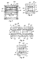
- the device 10 includes a stationary base structure including an upper plate member 12, a lower plate member 14, and spaced posts 16-22 connected therebetween.
- a fixed permanent magnet member 24 shown annular in shape which has one of its poles (its North pole) adjacent the upper surface of the upper plate (12) and its opposite pole (its South pole) spaced above the plate 12.
- the permanent magnet member 24 is shown having a plurality of coils 26-38 mounted in a coplanar relationship on the upper surface thereof. Seven coils are shown, and the coils 26-38 have electrical connections made through the plate 12 to other circuit members which will be described later in connection with Fig. 13.
- Another member 40 is mounted on the upper surface of the lower plate 14 and a similar member 42 is mounted on the underside of the plate 12.
- a shaft 44 (shown oriented vertically for convenience) extends through aligned bores in the members 42, 12 and 24.
- the lower end of the shaft 44 is connected to a disk member 46 which has a pair of spaced arcuate openings 48 and 50 shown located in diametrically opposite positions inwardly from the edge of the disk 46. The purpose for the openings 48 and 50 will be explained hereinafter.
- the shaft 44 is also connected to another annular member 52 which is located on the shaft so as to be positioned adjacent to the coils 26-38.
- the member 52 is shown as disk shaped and it has a pair of spaced permanent magnet members 54 and 56 mounted on or in it at spaced locations shown diameterically opposite to one another (see Fig. 2).
- the magnetic members 54 and 56 have their north and south poles oriented as shown in Fig. 2, that is with north poles shown on their lower sides and their south poles on the upper sides. This is done so that there will be mutual magnetic attraction and coupling between the magnets 54 and 56 and the fixed magnetic member 24.
- the polarity of the magnets 54 and 56 and/or of the magnet 24 can also be reversed if desired for some purposes to produce relative magnetic repulsion therebetween.
- the lower plate member 40 is shown having a plurality of phototransistors 58-70 mounted on the upper surface thereof at spaced locations therearound.
- the number and locations of the phototransistors 58-70 are such as to be in alignment substantially with the centers of the respective coils 26-38 that are mounted on the member 24.
- a similar number of infrared emitters 72-84 are mounted on the undersurface of the member 42 in alignment with the respective phototransistors.
- This arrangement is such that when the shaft 44 and the members attached thereto, including the disk 46 and the member 52, rotate relative to the other members including the member 24, the arcuate openings 48 and 50 will pass between the respective pairs of infrared emitters and in so doing will cause the phototransistors periodically to be in optical communication with the respective infrared emitters for predetermined time intervals.
- the purpose of this communication is to establish a sequence of energizing circuits to energize the respective coils 26-38, one at a time, so that each coil in turn will cause a momentary interruption of the magnetic interaction or a portion thereof between respective ones of the permanent magnets 54 and 56 and the magnet member 24.
- a coil When a coil is mounted on top of a permanent magnet such as permanent magnet 24 and energized it acts to concentrate the flux in a symmetrical magnetic field resulting in a non symmetrical field when another permanent magnet is placed above the coil that is located on the first permanent magnet 24. This will result in uneven or non-uniform forces being produced when the coil is energized causing a torque between the two permanent magnets, which torque will be in the direction to try to move one of the permanent magnets relative to the other.
- FIG. 3 there is shown the position of one of the magnet members 54 located immediately adjacent to one of the coils such as the coil 26. In this position there would be magnetic coupling between the magnets 54 and 24 so long as there is no voltage across the coil 26. However, if a voltage is placed across the coil 26 it will interrupt the magnetic coupling between the magnets 54 and 24 where the coil resides. This means that if there is any torque developed, it will be developed to either side of the coil 26. Without energizing the coil 26 there will be full attraction between the magnets 24 and 54 and no rotational force will be produced.
- Fig. 4 there is shown the relative positions of the movable magnets 54 and 56 for one position of the member 52.
- the magnet 54 is shown located immediately above the coil 26 while the magnet 56 is shown straddling portions of the coils 32 and 34. If, in this position of the members, the coil 32 is energized but the coils 34 and 26 are not energized then the magnetic coupling between the magnet 56 and the magnet 24 will be oriented at an angle shown illustrated by the arrow in Fig. 4, and this attractive coupling will tend to move the member 52 to the right as shown in Fig. 4.
- the member 52 As the member 52 continues to rotate different ones of the coils 26-38 will be energized in sequence to continue producing magnetic coupling force between the members 52 and 24 in a direction to produce relative rotation therebetween. It is to be noted, however that all of the rotational force is produced by interaction between permanent magnet members and none of the rotational force is produced by the coils or by any other means. The coils are merely energized in sequence to control where the magnetic interaction occurs, and this is done in a manner to cause the member 52 to rotate. It should also be understood that one or more, including more than two, permanent magnets such as the permanent magnets 54 and 56 can be mounted on the rotating member 52, and the shape and size of the rotating member 52 can be adjusted accordingly to accommodate the number of permanent magnets mounted therein. Also, the member 52 can be constructed of a non magnetic material, the only requirement being that sufficient structure be provided to support the permanent magnets during rotation. This means that the member 52 need not necessarily be constructed to be round as shown in the drawing.
- Figs. 5 and 6 are similar to Figs. 3 and 4 but show a construction wherein the permanent magnets 54 and 56 are overturned so that instead of having their north poles adjacent to the member 24 they have their south poles adjacent to the magnet 24 but on the opposite side of the coils such as coils 26-38.
- the construction and operation of the modified device illustrated by Figs. 5 and 6 is similar to that described above except that instead of producing magnetic attraction forces between the magnet members 54 and 56 and the magnet 24, magnetic repulsion forces are produced, and these repulsion forces can likewise be used in a similar manner to produce rotation of the member 52, whatever its construction.
- Fig. 7 shows a modified embodiment 100 of the subject device which includes all of the elements shown in Figs. 1 and 2 but in addition has a second stationary permanent magnet member 102 which is mounted above rather than below the member 52 and has its coil members such as coil members 26A-38A mounted on its underside.
- the magnetic member 102 operates with the magnets 54 and 56 similarly to the member 24 and can operate in precisely the same manner, that is by producing attraction force between the magnet members or by producing repulsion forces therebetween, each being used to produce relative rotational movement between the rotary portions of the device and the stationary portions. It is also contemplated to make the construction shown in Fig. 7 so as to produce attraction forces between the magnets 54 and 56 on one side thereof and cooperating repulsion forces which add to the rotation generating forces produced on the opposite sides thereof.
- Figs. 8 and 9 are similar to Figs. 3 and 4 but show the relationship between the magnets 54 and 56 and the members 24 and 102 located on opposite sides thereof.
- Fig. 9 shows arrows used to indicate the direction of the rotational forces produced that are necessary for rotating the rotatable portions of the device. These figures show one form of interaction between the rotating magnets 54 and 56 and the stationary magnets 24 and 102 located as shown in Fig. 7. In this construction the device produces attractive rotating force only.
- Figs. 10 and 11 are similar to Figs. 8 and 9 except that in these figures both attraction and repulsion forces are shown being produced in association with the stationary magnets on opposite sides of the rotating magnets. Note also that the coils being energized on opposite sides of the member 52 are energized in a different arrangement.
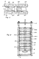
- Fig. 12 is a side elevational view similar to Fig. 7 but illustrating the way in which a plurality of stationary and rotatable magnetic members such as the members 24 and 102 can be mounted on the same shaft, in almost any number of repetative groups to increase the amount of torque produced by the device.
- the same power source and the same circuit arrangement can be used to energize the phototransistors and the infrared emitters. However, depending upon whether attraction or repulsion forces are used to produce the rotation or some combination thereof will depend upon the order in which the coils associated with the stationary magnetic members are energized.
- Fig. 13 is a circuit diagram for the device shown in Figs. 1 and 2, showing the circuit connections for the coils 26-38 and for the circuit elements associated therewith. A similar circuit can be used for the construction shown in Figs. 7 and 12. The circuit also includes connections to the various phototransistors and infrared emitters.
- the circuit 120 is shown including a power supply 122 which may be a battery power supply, a rectified AC power supply or an AC or pulsed power supply.
- the positive side 124 of the power supply 122 is shown connected to one side of each of the coils 26-38, coil 26 and the circuits associated therewith being shown in bold outline and including connections to one side of a resistor 128 and to one side of the photo transistors 58-70.
- the opposite side of the coil 26 is connected to one terminal of Mosfet 126.
- the opposite side of the resistor 128 is connected to one side of the infrared emitter 72, as well as to the corresponding sides of all of the other infrared emitters 74-84.
- the opposite sides of the infrared emitters 72-84 are connected by lead 130 to the negative terminal side 132 of the power supply 122.
- the infrared emitters 72-84 are all continuously energized and produce light which can be seen by the respective phototransistors 58-70 when one of the openings 48 or 50 passes therebetween.
- the respective phototransistor 58 will conduct and in so doing will apply positive voltage on the associated Mosfet 126, turning the Mosfet on, and causing the voltage of the source 122 to also be applied across the coil 26.
- the circuit for this is from the source 122 through the coil 26, through the Mosfet 126 to and through the lead 134 to the opposite side of the source 122.
- the coil 26 When the supply voltage is applied across the coil 26, the coil 26 operates to limit or prevent magnetic communication between whichever one of the magnets 54 or 56 happens to be positioned adjacent to the coil 26 which is in the space between that magnet 54 or 56 and the magnet 24.
- This circuit is shown darkened in Fig. 13.
- the magnetic coupling between the magnets 54 and 56 and the magnet 24 can be accurately controlled and in a manner to cause angular magnetic attraction between the magnet 54 (or 56) and the magnet 24, which angular attraction (or repulsion) is in a direction to cause rotation of the rotating parts of the structure shown in Figs. 1, 2, 7 and 12.
- each of the coils 26-38 will be controlled in the same manner, that is, will have a voltage appearing across it at the proper time to control the direction of the magnetic coupling in a manner to produce rotation.
- the rotating portions will continue to rotate and the speed of rotation can be maintained at any desired speed.
- Various means can be used to control the speed of rotation such as by controlling the timing of the DC or other voltage applied to the various coils, such as by using an alternating or pulsed current source instead of a direct current source or by loading the device to limit its rotational speed.
- the present device can be made to have any number of stationary and rotating magnets arranged in stacked relationship to increase the power output, (see Fig. 12) and it is also possible to use any desired number of coils mounted on the various stationary magnets. In the constructions shown in Figs. 1, 7, and 12 seven coils are shown mounted on each of the stationary magnets but more or fewer coils could be used on each of stationary magnet depending upon the power and other requirements of the device. If the number of coils is changed the number of light sources and photodetectors or transistors will change accordingly. It is also important to note that the timing of the turning on of the various phototransistors is important. The timing should be such as that illustrated in Fig. 4, for example, when one of the coils such as coil 32 is energized to prevent coupling in one direction between the magnet 56 and the magnet 24 the adjacent coil 34 will not be energized. The reasons for this have already been explained.
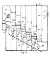
- the embodiment 140 includes a stationary permanent magnet 142 which has a flat upper surface 144 and a lower surface 146 that is circumferentially helical so that the member 142 varies in thickness from a location of maximum thickness at 148 to a location of minimum thickness at 150.
- the thickness of the member 142 is shown varying uniformly therearound.
- An air coil 152 Near the location of the thickest portion 148 of the permanent magnet 142 and adjacent to the surface 144 is an air coil 152 shown formed by a plurality of windings.
- a shaft member 154 is journalled by bearing means 156 for rotation relative to the stationary permanent magnet 142 and is connected to a rotating member 158.
- the member is shown annular in shape and includes four spaced permanent magnets 160, 162, 164 and 166 mounted on or in it.
- the permanent magnets 160-166 are positioned to rotate in closely spaced relation to the stationary permanent magnet 142 but with the coil 152 positioned therebetween.
- the coil 152 is connected into a circuit similar to that shown in Fig. 13 and the circuit will not be described further.
- the permanent magnets 160-166 rotate relative to the permanent magnet 142 because of the increasing coupling between them and the permanent magnet due to the increasing peripheral thickness of the permanent magnet.
- the member 158 will rotate in a counterclockwise direction as shown, and each time one of the magnets 160-166 moves into a position adjacent to the thickest portion 148 of the fixed permanent magnet 142 the coil 152 will have voltage applied across it, otherwise there would be a tendency for the member 158 to stop or reduce the rotational force.
- the coil 152 is energized each time one of the permanent magnets 160-166 is in the position shown.
- the rotating disc 158 is connected through the shaft 154 to rotating disc 168 which has four openings 170, 172, 174 and 176 corresponding to the locations of the permanent magnets 160-166 so that each time one of the permanent magnets moves to a position adjacent to the thickest portion 148 of the stationary permanent magnet 142 the coil 152 will be energized and this will reduce or eliminate the coupling between the rotating and stationary magnets that would otherwise slow the rotating portions down.
- the circuit connected to the coil 152 includes the same basic elements described above in connection with Fig. 13 including varying a photocell 178, an infrared emitter 180 and a Mosfet 182 connected into a circuit such as that shown in Fig. 13.
- the timing of the energizing of the coil 152 is important and should be such that the coil will be energized as the respective permanent magnets 160-166 move to a position in alignment or substantial alignment with the thickened portion 148 of the stationary permanent magnet 142.
- Fig. 15 shows a basic simplified form 190 of the present device which includes a rotary member 52A having a single permanent magnet portion 54A mounted thereon.
- the device also has a stationary permanent magnet 24A with a single air coil 26A positioned in the space between the members 52A and 24A in the manner already described.
- the construction 190 is not self-starting as are the preferred embodiments such as embodiment 10 but the rotary portions will rotate continuously once the device is started as by manually rotating the rotary portions.
- the construction 190 will have other portions as described above but the output from the construction will be less than the output produced by the other constructions.
- Fig. 16 shows another simplified version 200 of the device wherein the member 52B is similar to the corresponding rotatable member 52A shown in Fig. 15.
- the fixed structure including the permanent magnet 24B has three windings 26B, 28B and 30B located at spaced intervals adjacent to the upper surface thereof.
- the construction shown in Fig. 16 will produce more output than the construction shown in Fig. 15 but less than that of the other constructions such as that shown in Figs. 1, 2, 7 and 12.
- Obviously many other variations of the constructions shown in the application are also possible including constructions having more or fewer coils, more or fewer rotating magnetic portions, more or fewer rotary members such as the member 52 and more or fewer stationary members such as the members 24 and 142.
- FIGS. 17-25 illustrate some of the underlying principles of the present invention.
- Figs. 17 shows an air coil 210, positioned in space, with an electric potential applied thereacross. With the energizing voltage applied the electro-magnetic field of the air coil 210 extends substantially equally in the space above and below the coil as shown in dotted outlined.
- Fig. 18 shows the air coil 210 positioned adjacent to one side (the north side) of permanent magnet 212.
- no voltage is applied across the air coil 210 and therefore the air coil 210 does not produce an electro-magnetic field as in Fig. 17.
- the air coil 210 has no effect on the magnetic field of the permanent magnet 212 and the field of the permanent magnet is substantially as shown by the dotted outlines in Fig. 18.
- Fig. 19 is similar to Fig. 18 except that in Fig. 19 the air coil 210 has an electric potential applied across it and therefore has an established electro-magnetic field shown again by dotted outline.
- the electro-magnetic field of the air coil 210 modifies the magnetic field of the permanent magnet 212 in the manner shown. If the coil 210 is placed in contact with the surface of the permanent magnet and it is energized so that its polarity is opposite to that of the permanent magnet then the field produced is similar to that shown in Fig. 19. Note that the field of the air coil 210 is forced upwardly a greater distance than otherwise would be the case if the air coil 210 were not positioned adjacent to the permanent magnet 212.
- the field of the air coil 210 above the permanent magnet 212 is also more concentrated, that is, there are more lines per square inch than is the case in Fig. 17. This is because the lines that existed below the coil before it was placed adjacent to the permanent magnet 212 must now share the space above the coil with the lines that occupy this space.
- the field of the air coil 210 modifies the shape of the magnetic field of the permanent magnet 212 so that the field of the permanent magnet occupying the space below the air coil 210 must share the same area as the flux that occupied the perimeter of the coil 210 before energizing. Therefore, the flux of the permanent magnet 212 is more concentrated at the perimeters of the air coil 210.
- the intensity of the electro-magnetic field of the coil 210 at the location above the coil 210 is increased and magnetic field of the permanent magnet at other locations is increased.
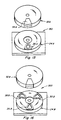
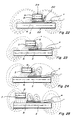
- Fig. 20 is similar to Fig. 19 except that a second permanent magnet 214 is positioned at a location spaced above the air coil 210. In Fig. 20 no voltage is applied across the air coil 210 and therefore the air coil 210 does not have an electro-magnetic field. Thus Fig. 20 shows only the combined affect of the fields of the permanent magnets 212 and 214. Since the permanent magnets 212 and 214 are oriented so that their respective north and south poles are close together, there will be a strong attractive force between them it the location of the air coil 210.
- Fig. 21 is a view similar Fig. 20 but wth an electric potential applied across the air coil 210 and with the upper permanent magnet 214 displaced to the left relative to its position in Fig. 20.
- the shape of the electro-magnetic field of the air coil 210 is concentrated and shifted somewhat to the right and upward. This shift of the electro-magnetic field concentrates the magnetic coupling between the magnets 212 and 214 to the left thereby increasing the tendency of the upper permanent magnet 214 to move to the left.
- a much smaller magnetic coupling occurs between the right end of the permanent magnets 212 and 214 and thus the force tending to move the permanent magnet 214 to the right is much less than the force tending to move it to the left. This is illustrated by the size of the arrows shown in Fig. 21.
- Figs. 22-25 show four different positions of the upper permanent magnet 214 relative to the lower permanent magnet 212.
- Fig. 22 because of the position of the upper permanent magnet 214 relative to the air coil 210 there is a concentration of the magnetic coupling force tending to move the upper permanent magnet 214 to the left.
- This force increases in Figs. 23 and 24 until the upper permanent magnet 214 reaches the position shown in Fig. 25 where all of the magnetic coupling is directed substantially vertically between the permanent magnets 212 and 214 and in this position there is little or no torque as a result of coupling energy between the permanent magnets 212 and 214 tending to move them relative to one another.
- Figs. 17-25 The principals illustrated in Figs. 17-25 are at the heart of the present invention and explain where the energy comes from to produce relative movement between the relatively moveable permanent magnets.
- the present device has application for very many different purposes and applications including almost any purpose where a motor or engine drive is required and where the amount of energy available and/or required to produce the driving force maybe very little to nil.
- Applicant has produced devices of the type described herein capable of rotating at very high speed in the order of magnitude of 20,000 RPMs and with substantial torque. Other lesser speeds can also be produced, and the subject device can be made to be self starting as is true of the constructions shown in Figs. 1, 2, 7 and 12. Because of the low power required to operate the device applicant has been able to operate same using a commercially available battery such as a nine volt battery.
Abstract
Description
- The present invention is an improvement over the inventions disclosed in Flynn et al and Flynn pending US patent applications Serial Nos. 07/322,121 US-A-5 304 881 and 07/828,703, US-A-5 463 263 filed March 13, 1989 and January 31, 1992 respectively. The devices disclosed in the pending applications relate to means to produce useful energy using permanent magnets as the driving source. This is also true of the present invention which represents an important improvement over the known constructions and one which is simpler to construct, can be made to be self starting, is easier to adjust, and is less likely to get out of adjustment. The present construction is also relatively easy to control, is relatively stable and produces an amazing amount of output energy considering the source of driving energy that is used. The present construction, like the constructions disclose in the earlier applications, makes use of permanent magnets as the source of driving energy but teaches a novel means of controlling the magnetic interaction or coupling between the magnet members and in a manner which is relatively rugged, produces a substantial amount of output energy and torque, and in a device capable of being used to generate substantial amounts of energy that is useful for many different purposes.
- US patent 3,670,189 discloses a gated permanent magnet device having two stator assemblies of a number of permanent magnets and a number of high permeability soft iron cores which are combined into hybrid magnetic poles. A rotatable multipole permanent magnet is sandwiched between the two stator assemblies. This rotor is caused to rotate by a gating action which alternates the poles one complete cycle with each transverse passing of the rotor poles between the stator poles.
- The present invention provides a magnetic device as defined in claim 1.
- The present invention resides in a fixed support structure having one or more fixed permanent magnets such as an annular permanent magnet mounted thereon with the pole faces of the permanent magnet located adjacent opposite faces thereof. The device has one or a plurality of relatively flat coils arranged in a coplanar manner about the periphery on one of the opposite faces of the fixed permanent magnet, and it has means for journaling a shaft member that extends through the permanent magnet with one or more other permanent magnet members attached thereto at spaced locations, each of the one or more spaced magnets having one of its magnetic poles positioned adjacent to the fixed permanent magnet with the plane of the coils positioned therebetween, the spaced permanent magnets and the fixed permanent magnet having their polarities arranged to produce a magnetic interaction such as magnetic coupling or magnetic repulsion therebetween. The device also includes journal means for supporting the shaft member and the spaced permanent magnet members for rotation relative to the fixed magnet and to the coils thereon, and means for selectively and sequentially energizing the coils located in a plane or space between fixed and movable magnets to predeterminately control the magnetic interaction forces between the respective spaced permanent magnet members and the fixed magnet in such a manner as to produce relative rotation therebetween. Various means can be used to control the application of energy to the coils including timer means under control of means mounted on the shaft for rotation therewith and a source of energy. The present construction can be made to be self starting or to be started with some initial help to establish rotation.
- It is a principal object of the present invention to teach the construction and operation of a relatively simple, motor-like device using permanent magnets in an unique manner to generate rotational or other forms of movement.
- Another object is to teach the construction and operation of a relatively simple, motor-like device having novel means for coupling and/or decoupling relatively moveable permanent magnets to produce motion.
- Another object is to provide novel means for controlling the coupling and decoupling of relatively moveable permanent magnets.
- Another object is to make the generation of rotational energy less expensive and more reliable.
- Another object is to teach a novel way of generating energy by varying magnetic interaction forces between permanent magnets.
- Another object is to provide an inexpensive way of producing energy.
- Another object is to provide a substitute source of energy for use in places where conventional motors, generators and engines are used.
- These and other objects and advantages of the present invention will become apparent after considering the following detailed specification of preferred embodiments in conjunction with the accompanying drawings.
-
- Fig. 1 is a side elevational view of a magnetically powered device constructed according to the present invention;
- Fig. 2 is an exploded view of the device shown in Fig. 1;
- Fig. 3 is a fragmentary elevational view showing a relationship between one of the movable magnet members and the non-movable magnet member in one position of the device;
- Fig. 4 is a view similar to Fig. 3 but showing the relationship between the other of the movable magnet members and the non-movable magnet member in the same position of the device;
- Fig. 5 is a fragmentary view similar to Fig. 3 but showing a repulsion interaction between the relatively movable permanent magnet members;
- Fig. 6 is a view similar to Fig. 4 for the condition shown in Fig. 5;
- Fig. 7 is a side elevational view showing another embodiment of the subject device which is capable of producing even greater energy and torque;
- Fig. 8 is a fragmentary elevational view similar to Fig. 3 for the device of Fig. 7;
- Fig. 9 is a view similar to Fig. 4 for the construction shown in Fig. 7;
- Fig. 10 is a view similar to Fig. 3 for the device shown in Fig. 7 but with the polarity of one of the fixed permanent magnet members reversed relative thereto;
- Fig. 11 is a fragmentary view similar to Fig. 4 for the device as shown in Figs. 7 and 10;
- Fig. 12 is a side elevational view of another embodiment of the device;
- Fig. 13 is a schematic circuit diagram of the circuit for the devices of Figs. 1, 7 and 12;
- Fig. 14 is a perspective view of another embodiment of the subject device;
- Fig. 15 is a simplified embodiment of the device showing the use of one rotating magnetic member and one coil positioned in the plane between the rotating and stationary magnetic members;
- Fig. 16 is a simplified embodiment of the device showing use of one movable magnetic member and three coils arranged to be in a plane between the rotating and stationary magnets.
- Fig. 17 is a side elevational view of an air coil with a voltage applied thereacross and showing in dotted outline the field of the coil;
- Fig. 18 is a view similar to Fig. 17 but showing the air coil positioned adjacent to one side of a permanent magnet showing in dotted outline the magnetic field of the permanent magnet with no electric potential applied across the air coil;
- Fig. 19 is a side elevational view similar to Fig. 18 with an electric potential applied across the air coil, said view showing in dotted outline the shapes of the electric field of the air coil and the magnetic field of the permanent magnet;
- Fig. 20 is a side elevational view similar to Fig. 19 but showing a second permanent magnet spaced above first permanent magnet and showing in dotted outline the magnetic fields of the two permanent magnets when no electric potential is connected across the air coil;
- Fig. 21 is a view similar to Fig. 20 but with the permanent magnets in an different relative position and with a voltage applied across the air coil, said view showing the shapes of the electro-magnetic field of the air coil and the modified shapes of the magnetic fields of the two permanent magnets; and
- Figs. 22-25 are similar to Fig. 21 and show the electro-magnetic field of the air coil and the magnetic fields of the magnets in four different relative positions of the permanent magnets.
- Referring to the drawings more particularly by reference numbers,
number 10 refers to a device constructed according to the present invention. Thedevice 10 includes a stationary base structure including anupper plate member 12, alower plate member 14, and spaced posts 16-22 connected therebetween. Mounted on theupper plate 12 is a fixedpermanent magnet member 24 shown annular in shape which has one of its poles (its North pole) adjacent the upper surface of the upper plate (12) and its opposite pole (its South pole) spaced above theplate 12. - Referring to Fig. 2, the
permanent magnet member 24 is shown having a plurality of coils 26-38 mounted in a coplanar relationship on the upper surface thereof. Seven coils are shown, and the coils 26-38 have electrical connections made through theplate 12 to other circuit members which will be described later in connection with Fig. 13. Anothermember 40 is mounted on the upper surface of thelower plate 14 and asimilar member 42 is mounted on the underside of theplate 12. - A
shaft 44, (shown oriented vertically for convenience) extends through aligned bores in themembers shaft 44 is connected to adisk member 46 which has a pair of spacedarcuate openings disk 46. The purpose for theopenings - The
shaft 44 is also connected to anotherannular member 52 which is located on the shaft so as to be positioned adjacent to the coils 26-38. Themember 52 is shown as disk shaped and it has a pair of spacedpermanent magnet members magnetic members magnets magnetic member 24. The polarity of themagnets magnet 24 can also be reversed if desired for some purposes to produce relative magnetic repulsion therebetween. - Referring again to Fig. 2, the
lower plate member 40 is shown having a plurality of phototransistors 58-70 mounted on the upper surface thereof at spaced locations therearound. The number and locations of the phototransistors 58-70 are such as to be in alignment substantially with the centers of the respective coils 26-38 that are mounted on themember 24. A similar number of infrared emitters 72-84 are mounted on the undersurface of themember 42 in alignment with the respective phototransistors. There are seven infrared emitters 72-84 shown, each of which is in alignment with a respective one of the seven phototransistors 58-70 and a respective one of the seven coils 26-38. This arrangement is such that when theshaft 44 and the members attached thereto, including thedisk 46 and themember 52, rotate relative to the other members including themember 24, thearcuate openings permanent magnets magnet member 24. - When a coil is mounted on top of a permanent magnet such as
permanent magnet 24 and energized it acts to concentrate the flux in a symmetrical magnetic field resulting in a non symmetrical field when another permanent magnet is placed above the coil that is located on the firstpermanent magnet 24. This will result in uneven or non-uniform forces being produced when the coil is energized causing a torque between the two permanent magnets, which torque will be in the direction to try to move one of the permanent magnets relative to the other. - Referring to Fig. 3 there is shown the position of one of the
magnet members 54 located immediately adjacent to one of the coils such as thecoil 26. In this position there would be magnetic coupling between themagnets coil 26. However, if a voltage is placed across thecoil 26 it will interrupt the magnetic coupling between themagnets coil 26. Without energizing thecoil 26 there will be full attraction between themagnets - Referring to Fig. 4 there is shown the relative positions of the
movable magnets member 52. For example, themagnet 54 is shown located immediately above thecoil 26 while themagnet 56 is shown straddling portions of thecoils coil 32 is energized but thecoils magnet 56 and themagnet 24 will be oriented at an angle shown illustrated by the arrow in Fig. 4, and this attractive coupling will tend to move themember 52 to the right as shown in Fig. 4. Since there is no energizing of thecoil 26 there will be full coupling between themagnet 54 and themember 24 but this will have no effect since it will neither be in a direction to rotate themember 52 or to stop it. At this same time thecoil 38 which is the next coil over which themagnet 54 will move is likewise deenergized and will therefore have no effect to produce rotational moment of themember 52. - As the
member 52 continues to rotate different ones of the coils 26-38 will be energized in sequence to continue producing magnetic coupling force between themembers member 52 to rotate. It should also be understood that one or more, including more than two, permanent magnets such as thepermanent magnets member 52, and the shape and size of the rotatingmember 52 can be adjusted accordingly to accommodate the number of permanent magnets mounted therein. Also, themember 52 can be constructed of a non magnetic material, the only requirement being that sufficient structure be provided to support the permanent magnets during rotation. This means that themember 52 need not necessarily be constructed to be round as shown in the drawing. - Figs. 5 and 6 are similar to Figs. 3 and 4 but show a construction wherein the
permanent magnets member 24 they have their south poles adjacent to themagnet 24 but on the opposite side of the coils such as coils 26-38. The construction and operation of the modified device illustrated by Figs. 5 and 6 is similar to that described above except that instead of producing magnetic attraction forces between themagnet members magnet 24, magnetic repulsion forces are produced, and these repulsion forces can likewise be used in a similar manner to produce rotation of themember 52, whatever its construction. - Fig. 7 shows a modified embodiment 100 of the subject device which includes all of the elements shown in Figs. 1 and 2 but in addition has a second stationary
permanent magnet member 102 which is mounted above rather than below themember 52 and has its coil members such ascoil members 26A-38A mounted on its underside. Themagnetic member 102 operates with themagnets member 24 and can operate in precisely the same manner, that is by producing attraction force between the magnet members or by producing repulsion forces therebetween, each being used to produce relative rotational movement between the rotary portions of the device and the stationary portions. It is also contemplated to make the construction shown in Fig. 7 so as to produce attraction forces between themagnets - Figs. 8 and 9 are similar to Figs. 3 and 4 but show the relationship between the
magnets members rotating magnets stationary magnets - Figs. 10 and 11 are similar to Figs. 8 and 9 except that in these figures both attraction and repulsion forces are shown being produced in association with the stationary magnets on opposite sides of the rotating magnets. Note also that the coils being energized on opposite sides of the
member 52 are energized in a different arrangement. - Fig. 12 is a side elevational view similar to Fig. 7 but illustrating the way in which a plurality of stationary and rotatable magnetic members such as the
members - Fig. 13 is a circuit diagram for the device shown in Figs. 1 and 2, showing the circuit connections for the coils 26-38 and for the circuit elements associated therewith. A similar circuit can be used for the construction shown in Figs. 7 and 12. The circuit also includes connections to the various phototransistors and infrared emitters.
- In Fig. 13, the
circuit 120 is shown including apower supply 122 which may be a battery power supply, a rectified AC power supply or an AC or pulsed power supply. Thepositive side 124 of thepower supply 122 is shown connected to one side of each of the coils 26-38,coil 26 and the circuits associated therewith being shown in bold outline and including connections to one side of aresistor 128 and to one side of the photo transistors 58-70. The opposite side of thecoil 26 is connected to one terminal ofMosfet 126. The opposite side of theresistor 128 is connected to one side of theinfrared emitter 72, as well as to the corresponding sides of all of the other infrared emitters 74-84. The opposite sides of the infrared emitters 72-84 are connected bylead 130 to the negativeterminal side 132 of thepower supply 122. With the circuit as shown, the infrared emitters 72-84 are all continuously energized and produce light which can be seen by the respective phototransistors 58-70 when one of theopenings respective phototransistor 58 will conduct and in so doing will apply positive voltage on the associatedMosfet 126, turning the Mosfet on, and causing the voltage of thesource 122 to also be applied across thecoil 26. The circuit for this is from thesource 122 through thecoil 26, through theMosfet 126 to and through thelead 134 to the opposite side of thesource 122. When the supply voltage is applied across thecoil 26, thecoil 26 operates to limit or prevent magnetic communication between whichever one of themagnets coil 26 which is in the space between thatmagnet magnet 24. This circuit is shown darkened in Fig. 13. By properly timing and controlling the application of voltage to the various coils 26-38 in the manner described, the magnetic coupling between themagnets magnet 24 can be accurately controlled and in a manner to cause angular magnetic attraction between the magnet 54 (or 56) and themagnet 24, which angular attraction (or repulsion) is in a direction to cause rotation of the rotating parts of the structure shown in Figs. 1, 2, 7 and 12. It is to be understood that each of the coils 26-38 will be controlled in the same manner, that is, will have a voltage appearing across it at the proper time to control the direction of the magnetic coupling in a manner to produce rotation. The rotating portions will continue to rotate and the speed of rotation can be maintained at any desired speed. Various means can be used to control the speed of rotation such as by controlling the timing of the DC or other voltage applied to the various coils, such as by using an alternating or pulsed current source instead of a direct current source or by loading the device to limit its rotational speed. - It is especially important to note that the energy required to operate the subject device is minimal since very little current is drawn when voltage is applied across the various coils when they are energized.
- A well known equation used for conventional motor art, a well known formula is:


- This equation has limited application to the present device because in the present device the torque is believed to be constant while the speed is the variable. The same equation can be rewritten:

- It should be understood that the present device can be made to have any number of stationary and rotating magnets arranged in stacked relationship to increase the power output, (see Fig. 12) and it is also possible to use any desired number of coils mounted on the various stationary magnets. In the constructions shown in Figs. 1, 7, and 12 seven coils are shown mounted on each of the stationary magnets but more or fewer coils could be used on each of stationary magnet depending upon the power and other requirements of the device. If the number of coils is changed the number of light sources and photodetectors or transistors will change accordingly. It is also important to note that the timing of the turning on of the various phototransistors is important. The timing should be such as that illustrated in Fig. 4, for example, when one of the coils such as
coil 32 is energized to prevent coupling in one direction between themagnet 56 and themagnet 24 theadjacent coil 34 will not be energized. The reasons for this have already been explained. - Referring to Fig. 14, there is shown another
embodiment 140 of the subject device. Theembodiment 140 includes a stationarypermanent magnet 142 which has a flatupper surface 144 and alower surface 146 that is circumferentially helical so that themember 142 varies in thickness from a location of maximum thickness at 148 to a location of minimum thickness at 150. The thickness of themember 142 is shown varying uniformly therearound. Near the location of thethickest portion 148 of thepermanent magnet 142 and adjacent to thesurface 144 is anair coil 152 shown formed by a plurality of windings. Ashaft member 154 is journalled by bearingmeans 156 for rotation relative to the stationarypermanent magnet 142 and is connected to a rotatingmember 158. The member is shown annular in shape and includes four spacedpermanent magnets permanent magnet 142 but with thecoil 152 positioned therebetween. Thecoil 152 is connected into a circuit similar to that shown in Fig. 13 and the circuit will not be described further. - The principles of operation of the
device 140 shown in Fig. 14 are similar to that described above in connection with Figs. 1 and other figures. It is important to note, however, that the permanent magnets 160-166 rotate relative to thepermanent magnet 142 because of the increasing coupling between them and the permanent magnet due to the increasing peripheral thickness of the permanent magnet. Thus themember 158 will rotate in a counterclockwise direction as shown, and each time one of the magnets 160-166 moves into a position adjacent to thethickest portion 148 of the fixedpermanent magnet 142 thecoil 152 will have voltage applied across it, otherwise there would be a tendency for themember 158 to stop or reduce the rotational force. In order to overcome this thecoil 152 is energized each time one of the permanent magnets 160-166 is in the position shown. Therotating disc 158 is connected through theshaft 154 torotating disc 168 which has fouropenings thickest portion 148 of the stationarypermanent magnet 142 thecoil 152 will be energized and this will reduce or eliminate the coupling between the rotating and stationary magnets that would otherwise slow the rotating portions down. The circuit connected to thecoil 152 includes the same basic elements described above in connection with Fig. 13 including varying aphotocell 178, aninfrared emitter 180 and aMosfet 182 connected into a circuit such as that shown in Fig. 13. The timing of the energizing of thecoil 152 is important and should be such that the coil will be energized as the respective permanent magnets 160-166 move to a position in alignment or substantial alignment with the thickenedportion 148 of the stationarypermanent magnet 142. - Fig. 15 shows a basic
simplified form 190 of the present device which includes arotary member 52A having a single permanent magnet portion 54A mounted thereon. The device also has a stationary permanent magnet 24A with asingle air coil 26A positioned in the space between themembers 52A and 24A in the manner already described. Theconstruction 190 is not self-starting as are the preferred embodiments such asembodiment 10 but the rotary portions will rotate continuously once the device is started as by manually rotating the rotary portions. Theconstruction 190 will have other portions as described above but the output from the construction will be less than the output produced by the other constructions. - Fig. 16 shows another
simplified version 200 of the device wherein the member 52B is similar to the correspondingrotatable member 52A shown in Fig. 15. However, the fixed structure including the permanent magnet 24B has three windings 26B, 28B and 30B located at spaced intervals adjacent to the upper surface thereof. The construction shown in Fig. 16 will produce more output than the construction shown in Fig. 15 but less than that of the other constructions such as that shown in Figs. 1, 2, 7 and 12. Obviously many other variations of the constructions shown in the application are also possible including constructions having more or fewer coils, more or fewer rotating magnetic portions, more or fewer rotary members such as themember 52 and more or fewer stationary members such as themembers - Figs. 17-25 illustrate some of the underlying principles of the present invention.
- Figs. 17 shows an
air coil 210, positioned in space, with an electric potential applied thereacross. With the energizing voltage applied the electro-magnetic field of theair coil 210 extends substantially equally in the space above and below the coil as shown in dotted outlined. - Fig. 18 shows the
air coil 210 positioned adjacent to one side (the north side) ofpermanent magnet 212. In Fig. 18 no voltage is applied across theair coil 210 and therefore theair coil 210 does not produce an electro-magnetic field as in Fig. 17. Under these circumstances theair coil 210 has no effect on the magnetic field of thepermanent magnet 212 and the field of the permanent magnet is substantially as shown by the dotted outlines in Fig. 18. - Fig. 19 is similar to Fig. 18 except that in Fig. 19 the
air coil 210 has an electric potential applied across it and therefore has an established electro-magnetic field shown again by dotted outline. The electro-magnetic field of theair coil 210 modifies the magnetic field of thepermanent magnet 212 in the manner shown. If thecoil 210 is placed in contact with the surface of the permanent magnet and it is energized so that its polarity is opposite to that of the permanent magnet then the field produced is similar to that shown in Fig. 19. Note that the field of theair coil 210 is forced upwardly a greater distance than otherwise would be the case if theair coil 210 were not positioned adjacent to thepermanent magnet 212. The field of theair coil 210 above thepermanent magnet 212 is also more concentrated, that is, there are more lines per square inch than is the case in Fig. 17. This is because the lines that existed below the coil before it was placed adjacent to thepermanent magnet 212 must now share the space above the coil with the lines that occupy this space. In like manner, the field of theair coil 210 modifies the shape of the magnetic field of thepermanent magnet 212 so that the field of the permanent magnet occupying the space below theair coil 210 must share the same area as the flux that occupied the perimeter of thecoil 210 before energizing. Therefore, the flux of thepermanent magnet 212 is more concentrated at the perimeters of theair coil 210. Thus for the same amount of electrical input applied to thecoil 210 shown in Fig. 17 the intensity of the electro-magnetic field of thecoil 210 at the location above thecoil 210 is increased and magnetic field of the permanent magnet at other locations is increased. - Fig. 20 is similar to Fig. 19 except that a second
permanent magnet 214 is positioned at a location spaced above theair coil 210. In Fig. 20 no voltage is applied across theair coil 210 and therefore theair coil 210 does not have an electro-magnetic field. Thus Fig. 20 shows only the combined affect of the fields of thepermanent magnets permanent magnets air coil 210. - Fig. 21 is a view similar Fig. 20 but wth an electric potential applied across the
air coil 210 and with the upperpermanent magnet 214 displaced to the left relative to its position in Fig. 20. Note that in Fig. 21 the shape of the electro-magnetic field of theair coil 210 is concentrated and shifted somewhat to the right and upward. This shift of the electro-magnetic field concentrates the magnetic coupling between themagnets permanent magnet 214 to move to the left. A much smaller magnetic coupling occurs between the right end of thepermanent magnets permanent magnet 214 to the right is much less than the force tending to move it to the left. This is illustrated by the size of the arrows shown in Fig. 21. - Figs. 22-25 show four different positions of the upper
permanent magnet 214 relative to the lowerpermanent magnet 212. In Fig. 22 because of the position of the upperpermanent magnet 214 relative to theair coil 210 there is a concentration of the magnetic coupling force tending to move the upperpermanent magnet 214 to the left. This force increases in Figs. 23 and 24 until the upperpermanent magnet 214 reaches the position shown in Fig. 25 where all of the magnetic coupling is directed substantially vertically between thepermanent magnets permanent magnets - The principals illustrated in Figs. 17-25 are at the heart of the present invention and explain where the energy comes from to produce relative movement between the relatively moveable permanent magnets.
- The present device has application for very many different purposes and applications including almost any purpose where a motor or engine drive is required and where the amount of energy available and/or required to produce the driving force maybe very little to nil. Applicant has produced devices of the type described herein capable of rotating at very high speed in the order of magnitude of 20,000 RPMs and with substantial torque. Other lesser speeds can also be produced, and the subject device can be made to be self starting as is true of the constructions shown in Figs. 1, 2, 7 and 12. Because of the low power required to operate the device applicant has been able to operate same using a commercially available battery such as a nine volt battery.
- Thus there has been shown and described a novel magnetic motor or motor-like construction which fulfills all of the objects and advantages sought therefor. It will be apparent to those skilled in the art, however, that many changes, variations, modifications and other uses in applications for the subject device are possible. All such changes, variations, modifications and other uses in applications which do not depart from the scope of the invention are deemed to be covered by the invention which is limited only by the claims which follow.
Claims (25)
- A magnetic device (10) comprising:a first permanent magnet member (24) having opposite surfaces with north and south poles respectively;a second permanent magnet member (54) spaced from and movable relative to the first permanent magnet (24) and having opposite surfaces with north and south poles respectively, one of which is positioned in close enough proximity to one of the surfaces of the first permanent magnet member (24) to produce a magnetic interaction therebetween;at least one coil (26) of conductive metal mounted in a fixed relationship with respect to the first permanent magnet member (24)a source of electric potential (122) and switch means (126) connected in series therewith across the coil (26) whereby when the switch means (126) are closed the electric potential from the source (122) is applied across the coil (26) and the magnetic interaction between the first (24) and second (54) permanent magnets is changed; andmeans (72,58) to control the opening and closing of the switch means (126).characterised in that the coil (26) is positioned in the gap between the first (24) and second (54) permanent magnet members;and in that the polarity of the coil (26) when energised is such as to cause an interruption of the magnetic interaction or a portion thereof between the first (24) and second (54) permanent magnet members.
- A magnetic device (10) according to claim 1 characterised in that the magnetic interaction between the first (24) and second (54) permanent magnet members is changed in a predetermined manner.
- A magnetic device (10) according to claim 1 or 2 characterised in that the first (24) and second (54) permanent magnet members are mounted to produce magnetic attraction therebetween.
- A magnetic device (10) according to claim 1 or 2 characterised in that the first (24) and second (54) permanent magnet members are mounted to produce magnetic repulsion therebetween.
- A magnetic device (10) according to any one of the preceding claims characterised in that the second permanent magnet member (54) includes means (44) mounting the second permanent magnet member (54) for rotational movement relative to the first permanent magnet member (24) and the switch means (126) includes cooperative optical means having a first portion (58) associated with the first permanent magnet member (24) and a second portion (72) mounted for movement with the second permanent magnet member (54).
- A magnetic device (10) according to claim 5 characterised in that the switch means (126) includes a light source (72) and a light sensitive member (58) associated respectively with the first (24) and second (54) permanent magnet members, and control means (48,50) therefor mounted for movement with the second permanent magnet member (54).
- A magnetic device (10) according to any one of the preceding claims characterised in that the first permanent magnet member (24) is an annular permanent magnet member having one of its poles on one side of the gap and the other of its poles opposite thereto, the second permanent magnet member (54) includes means (44) mounting the second permanent magnet member (54) for rotational movement relative to the first permanent magnet member (24), said second permanent magnet member (54) having one of its poles on one side of the gap, and there is provided a plurality of circumferentially spaced coils (26-38) mounted in the gap between the first (24) and second (54) permanent magnet members.
- A magnetic device (10) according to claim 7 characterised in that the second permanent magnet member (54) includes two circumferentially spaced portions (54,56).
- A magnetic device (10) according to claim 1 characterised in that:there is provided a member (52) journalled for rotational movement about an axis of rotation;at least a portion adjacent the periphery of the rotatable member (52) is formed of the second permanent magnet member (54);the first permanent magnet member (24) is formed as a stationary member mounted adjacent to the peripheral portion of the rotatable member (52) and axially spaced therefrom, whereby a magnetic interaction is produced between the stationary (24) and the rotatable (52) members in predetermined positions of the rotatable member (52);the coil (26) is positioned in the space between the stationary (24) and rotatable (52) members; andthe means (48,50) to control the opening and closing of the switch means (126) predeterminately controls the opening and closing of the switch means (126) during rotation of the rotatable member (52) to vary the magnetic interaction in a way to produce rotation of the rotatable member (52).
- A magnetic device (10) according to claim 1 characterised in that it further comprises:a support structure (12,14) having the first permanent magnet member (24) mounted thereon;means (52) for mounting the second permanent magnet member (54) for rotational movement in a plane parallel to the first permanent magnet member (24), the second permanent magnet member (54) occupying an arcuate portion of said mounting means (52) less than the entire circumference of said mounting means (52) and positioned so that there is magnetic interaction between the spaced first (24) and second (54) permanent magnet members across a gap therebetween in at least one position thereof; andwhereby the application of electric potential from the source (122) across the coil (26) is controlled by the switch means (126) to effect the magnetic interaction between the first (24) and second (54) permanent magnet members in certain positions of the second permanent magnet member (54) relative to the first permanent magnet member (24) and in such a manner as to produce rotational movement of the second permanent magnet member (54).
- A magnetic device (10) according to claim 10 characterised in that a third permanent magnet member (102) is mounted on the support structure (12,14) on the opposite side of the second permanent magnet member (54) from the first permanent magnet member (24) so as to establish a second gap therebetween and so that there is magnetic interaction between the second (54) and third (102) permanent magnet members, and at least one second coil (26A) mounted in the gap between the second (54) and third (102) permanent magnet members to predeterminately effect the magnetic interaction therebetween in certain positions of the second permanent magnet member (54) relative to the third permanent magnet member (102) thereby to contribute to the production of rotational movement of the second permanent magnet member (54) relative to the first (24) and third (102) permanent magnet members.
- A magnetic device (10) according to claim 11 characterised in that the switch means (126) for applying electrical potential from the source (122) across the coils (26-38) includes a light source (72) and light sensor (58), one mounted on the support structure (12,14) and the other on the rotatable means (52) to produce a switching action to apply and remove electric potential from across the coils (26-38) in predetermined positions of the second permanent magnet member (54) relative to the first (24) and third (102) permanent magnet members.
- A magnetic device (10) according to claim 1 characterised in that it further comprises:a shaft (44) having an axis and means journalling the shaft (44) for rotation in a position extending normal to the opposite surfaces of the first permanent magnet member (24);means (52) mounting the second permanent magnet member (54) on the shaft (44) for rotation therewith, the second permanent magnet member (54) occupying an arcuate portion of said mounting means (52) less than the entire circumference of said mounting means (52) and one pole of said second permanent magnet member (54) being positioned to move in close enough proximity to one of the opposite surfaces of the first permanent magnet member (24) to produce magnetic interaction therebetween;at least one coil (26) mounted in the gap between the fixed first permanent magnet member (24) and the movable second permanent magnet member (54) such that energizing the coils (26-38) from the source (122) of electric potential effects the magnetic interaction between the fixed first (24) and movable second (54) permanent magnet members when positioned therebetween; andmeans (48,50) connecting the coil (26) to the source (122) of electric potential in selected positions of the movable second permanent magnet member (54) relative to the fixed first permanent magnet member (24).
- A magnetic device (10) according to claim 13 characterised in that a plurality of the coils (26-38) is mounted in a coplanar relationship in the gap between the fixed first permanent magnet member (24) and the movable second permanent magnet member (54), the means connecting the coils (26-38) to the source (122) of electric potential including means for energizing the respective coils (26-38) in a predetermined sequence.
- A magnetic device (10) according to claim 13 or 14 characterised in that it further includes a further movable permanent magnet member (56) mounted on the means (52) mounting the movable second permanent magnet member (54) for movement therewith, said further movable permanent magnet member (56) being spaced circumferentially from the movable second permanent magnet member (54).
- A magnetic device (10) according to any one of claims 13 to 15 characterised in that a further fixed permanent magnet member (102) having opposite surfaces with north and south poles respectively adjacent thereto is mounted on the opposite side of the movable second permanent magnet member (54) from the fixed first permanent magnet member (24) and at least one coil (26A) is mounted in the gap between the further fixed permanent magnet member (102) and the movable second permanent magnet member (54).
- A magnetic device (10) according to any one of claims 13 to 16 characterised in that the means connecting the coil (26) to the source (122) of electric potential includes a fixed light source (72) and a fixed light sensitive member (58) mounted in spaced relationship and means (48,50) on the mounting means (52) for the movable second permanent magnet member (54) for predeterminately controlling communication between the light source (72) and the light sensitive member (58) during rotation of the movable second permanent magnet member (54).
- A magnetic device (10) according to claim 1 characterised in that it comprises:a fixed support structure (12,14) having the first permanent magnet member (24) mounted thereon;a plurality of the coils (26-38) mounted adjacent to and arranged about one of the opposite side faces of the first permanent magnet member (24);an orifice through the first permanent magnet member (24) at a location intermediate the coils (26-38);a shaft (44) extending through the orifice for rotation about the axis thereof;a member (52) attached to the shaft (44) for rotation therewith and spaced from the one opposite side face of the first permanent magnet member (24);at least one second permanent magnet member (54) attached to said rotating member (52) for rotation therewith, each of said rotating second permanent magnet members (54) having a magnetic pole face positioned in spaced relation to the one opposite side face of the fixed first permanent magnet member (24), the plurality of coils (26-38) being in the gap formed by and between the fixed first permanent magnet member (24) and the at least one rotatable second permanent magnet member (54); andmeans to selectively and sequentially energize the coils (26-38) as the shaft (44) rotates to predeterminately control the magnetic interaction between the at least one rotatable second permanent magnet member (54) and the fixed first permanent magnet member (24).
- A magnetic device (10) according to claim 18 characterised in that there is an odd number of coils (26-38) mounted in the gap between the first permanent magnet member (24) and the at least one rotatable second permanent magnet member (54).
- A magnetic device (10) according to claim 18 or 19 characterised in that the at least one second permanent magnet member (54) attached to the rotating member (52) for rotation therewith includes two circumferentially spaced rotatable magnet portions (54,56).
- A magnetic device (10) according to claim 1 characterised in that it comprises:a support structure having a wall member (12);a shaft (44) and means journalling the shaft (44) for rotation in the wall member (12) about its axis;the first permanent magnet member (24) being mounted on the wall member (12) and extending about at least a portion of the shaft (44), said first permanent magnet member (24) having one pole adjacent to the wall member (12) and an opposite pole spaced therefrom;a plurality of the coils (26-38) mounted in coplanar relation in the gap formed by and between the first permanent magnet member (24) and the second permanent magnet member (54);a member (52) mounted on the shaft (44) in closely spaced relation to the plurality of coils (26-38), said member (52) having at least two second permanent magnet members (54,56) mounted thereon or therein and oriented to produce magnetic interaction with the fixed first permanent magnet member (24); andmeans to sequentially apply electric potential across the respective coils (26-38) to vary the magnetic interaction between the first permanent magnet member (24) mounted on the wall member and selected one of the at least two second permanent magnet members (54,56).
- A magnetic device (10) according to claim 21 characterised in that the means to sequentially apply electric potential across the respective coils (26-38) applies the potential in a sequence so as to predeterminately affect the interaction between the fixed first permanent magnet member (24) and the rotatable second permanent magnet members in a manner to produce rotation of the at least two second permanent magnet members.
- A magnetic device (10) according to claim 1 characterised in that : the first permanent magnet member (24) comprises a fixed annular permanent magnet (142) having a flat surface on one side and an opposite surface of helical shape extending therearound from a location of minimum thickness to a location of maximum thickness approximately adjacent thereto, the annular permanent magnet (142) having one of its poles adjacent to the flat surface and its opposite pole adjacent to the helical opposite surface;the coil (26, 152) is positioned near the location of maximum thickness (148) of the first permanent magnet member (24);a shaft (44) having an axis and means journalling the shaft (44) for rotation in a position extends substantially normal to the flat surface of the fixed first permanent magnet member (24);means are provided to mount the second permanent magnet member (160) on the shaft (44) for rotation therewith, said second permanent magnet member (160) having opposite pole faces and being positioned so that there is magnetic interaction between said second permanent magnet member (160) and the fixed first permanent magnet member (24); andthe means to apply electric potential across the coil (152) applies an electric potential when the second rotatable permanent magnet member (160) is adjacent to the thickest portion of the fixed first permanent magnet member (24) to change the magnetic interaction therebetween, said last named means including a source (182) of voltage and switch means (180) in series with the source (182) for controlling the application of voltage across the coil (152).
- A magnetic device (10) according to claim 23 characterised in that a plurality of rotatable second permanent magnet members (160-166) are mounted at circumferentially spaced locations about the shaft (44) for magnetic interaction with the fixed annular first permanent magnet member (24), the switch means (180) controlling the application of voltage from the source (182) to the coil (152) when one of the rotatable second permanent magnet members (160-166) is positioned adjacent to the thickest portion of the fixed annular first permanent magnet member (142).
- A magnetic device (10) according to claim 23 or 24 characterised in that the switch means (180) includes cooperative optical means having a first portion (178) associated with the fixed annular first permanent magnet member (142) and a second portion (180) associated with the rotatable second permanent magnet member (160).
Applications Claiming Priority (2)
| Application Number | Priority Date | Filing Date | Title |
|---|---|---|---|
| US07/902,952 US5455474A (en) | 1992-06-23 | 1992-06-23 | Magnetic motor construction |
| US902952 | 1992-06-23 |
Publications (3)
| Publication Number | Publication Date |
|---|---|
| EP0576252A2 EP0576252A2 (en) | 1993-12-29 |
| EP0576252A3 EP0576252A3 (en) | 1994-08-31 |
| EP0576252B1 true EP0576252B1 (en) | 1997-08-20 |
Family
ID=25416680
Family Applications (1)
| Application Number | Title | Priority Date | Filing Date |
|---|---|---|---|
| EP93304861A Expired - Lifetime EP0576252B1 (en) | 1992-06-23 | 1993-06-22 | Magnetic motor construction |
Country Status (12)
| Country | Link |
|---|---|
| US (1) | US5455474A (en) |
| EP (1) | EP0576252B1 (en) |
| CN (1) | CN1038462C (en) |
| AT (1) | ATE157207T1 (en) |
| AU (1) | AU4633393A (en) |
| CA (1) | CA2146774C (en) |
| DE (1) | DE69313200T2 (en) |
| ES (1) | ES2108821T3 (en) |
| IL (1) | IL106082A0 (en) |
| TW (1) | TW226497B (en) |
| WO (1) | WO1994000903A1 (en) |
| ZA (1) | ZA934343B (en) |
Families Citing this family (30)
| Publication number | Priority date | Publication date | Assignee | Title |
|---|---|---|---|---|
| AU7075094A (en) * | 1993-06-28 | 1995-01-17 | Kone Oy | Elevator machinery |
| FI114419B (en) * | 1994-04-07 | 2004-10-15 | Kone Corp | The elevator machinery |
| FI93340C (en) * | 1993-06-28 | 1995-03-27 | Kone Oy | The elevator machine |
| JP3208471B2 (en) * | 1994-06-21 | 2001-09-10 | 大洋電産株式会社 | Fan motor |
| RU2098908C1 (en) * | 1995-03-07 | 1997-12-10 | Товарищество с ограниченной ответственностью "ПЭТРО-ФЭСТ" | Valve-type motor |
| GB9506461D0 (en) * | 1995-03-29 | 1995-05-17 | Switched Reluctance Drives Ltd | Single-phase variable reluctance motor having permanent magnets bedded within a phase winding |
| JP2000504196A (en) * | 1996-01-22 | 2000-04-04 | イリノイ トゥール ワークス インコーポレイティド | Magnetic pole shaft motor |
| US5925958A (en) * | 1996-06-20 | 1999-07-20 | Pirc; Anton | DC motor utilizing permanent magnets |
| US6348751B1 (en) | 1997-12-12 | 2002-02-19 | New Generation Motors Corporation | Electric motor with active hysteresis-based control of winding currents and/or having an efficient stator winding arrangement and/or adjustable air gap |
| GB2339627A (en) * | 1998-07-16 | 2000-02-02 | Ya Horng Electronic Co Ltd | A record player driving device |
| US6246561B1 (en) * | 1998-07-31 | 2001-06-12 | Magnetic Revolutions Limited, L.L.C | Methods for controlling the path of magnetic flux from a permanent magnet and devices incorporating the same |
| AU2002226087A1 (en) * | 2000-11-27 | 2002-06-03 | Frank J. Fecera | Permanent magnet motor |
| US6439855B1 (en) * | 2001-02-12 | 2002-08-27 | Siemens Automotive, Inc. | Direct current electric motor which eliminates outer case and places brushes and chokes in space efficient locations |
| US6806610B2 (en) * | 2001-02-27 | 2004-10-19 | Monte Dilliner | Magnetic motor with movable rotor and drive magnets |
| US20040055797A1 (en) * | 2002-02-19 | 2004-03-25 | Chester White | Electromagnetic, ''fuelless,'' passenger vehicle (automobile) |
| US7233088B2 (en) | 2003-01-17 | 2007-06-19 | Magnetic Torque International, Ltd. | Torque converter and system using the same |
| US7268454B2 (en) | 2003-01-17 | 2007-09-11 | Magnetic Torque International, Ltd. | Power generating systems |
| US7808142B2 (en) * | 2004-10-27 | 2010-10-05 | E3 Solutions, Llc | Multivariable generator and method of using the same |
| US20060087187A1 (en) * | 2004-10-27 | 2006-04-27 | Magnetic Torque International, Ltd. | Multivariable generator and method of using the same |
| US20060238055A1 (en) * | 2005-04-23 | 2006-10-26 | Danford Tiras J | Magnetic motor |
| US7868514B2 (en) * | 2006-12-19 | 2011-01-11 | TWM Technology, L.L.C. | Plural rotor permanent magnet electric motor with coincident electromagnetic axis |
| TW200913442A (en) * | 2007-09-05 | 2009-03-16 | Chuan-Sheng Chen | Coilless motor |
| US20100283347A1 (en) * | 2009-05-07 | 2010-11-11 | Clynton Caines | Novel ganged alternating current generator |
| US8344843B2 (en) | 2010-09-03 | 2013-01-01 | Solid State Magnetics Corporation | Flux transfer device |
| US9447728B2 (en) | 2010-09-18 | 2016-09-20 | Raymond Towne | Magnet-based anti-cogging apparatuses and systems for applying an anti-cogging torque on a rotating shaft |
| US8701615B2 (en) | 2010-09-18 | 2014-04-22 | Raymond A. Towne, III | Anti-cogging apparatus and methods for reducing cogging of rotating shaft |
| CN105659489A (en) * | 2013-10-14 | 2016-06-08 | 升旸科技有限公司 | Mobile induction and power-generation device |
| US10594192B1 (en) * | 2015-08-20 | 2020-03-17 | Anoup Kaul | Brushless motor/generator |
| CN105932847A (en) * | 2016-07-08 | 2016-09-07 | 程国强 | Magnetic suspension half-feed DC motor |
| EP4096068A1 (en) * | 2021-05-26 | 2022-11-30 | Mehmet Alkan | Generator device for converting kinetic energy into electrical energy |
Family Cites Families (20)
| Publication number | Priority date | Publication date | Assignee | Title |
|---|---|---|---|---|
| DE210005C (en) * | ||||
| BE515798A (en) * | 1951-11-28 | |||
| US3096467A (en) * | 1959-10-09 | 1963-07-02 | Ferranti Ltd | Brushless d. c. motor with permanent magnet rotor |
| DE1526380A1 (en) * | 1966-05-11 | 1970-06-18 | Daimler Benz Ag | Mixture-compressing rotary piston internal combustion engine |
| US3569806A (en) * | 1968-10-08 | 1971-03-09 | Harrison D Brailsford | Starting arrangement for solid-state commutated motor |
| US3670189A (en) * | 1971-04-30 | 1972-06-13 | Paul Peter Monroe | Gated permanent magnet motor |
| FR2146527A5 (en) * | 1971-07-16 | 1973-03-02 | Amouriq Paul | |
| FR2211791B1 (en) * | 1972-12-21 | 1977-08-12 | Akad Wissenschaften Ddr | |
| US4151431A (en) * | 1973-12-06 | 1979-04-24 | Johnson Howard R | Permanent magnet motor |
| DE2614450A1 (en) * | 1976-04-03 | 1977-10-13 | Jacke Gmbh & Co Kg | Electric machine for producing periodic mechanical movement - uses one or more movable permanent magnets arranged in magnetic field |
| US4187441A (en) * | 1977-03-23 | 1980-02-05 | General Electric Company | High power density brushless dc motor |
| FR2446555A1 (en) * | 1979-01-09 | 1980-08-08 | Martire Roger | Motor driven by EM modified permanent magnet fields - has permanent magnets on disc rotor, and surrounding coil with polarity controlled by commutator on shaft |
| JPS5725153A (en) * | 1979-10-20 | 1982-02-09 | Shoji Yonezawa | Coiled armature core with magnet capable of producting of stopping magnetic flux from magnet |
| EP0042884A1 (en) * | 1980-07-02 | 1982-01-06 | Roger Martire | Electromagnetically excited magnet motor |
| US4456858A (en) * | 1981-10-15 | 1984-06-26 | Loven James F | Permanent magnetic A.C.-D.C. motor |
| FR2563059B1 (en) * | 1984-04-13 | 1988-04-15 | Cem Comp Electro Mec | VERNIER ELECTRODYNAMIC MACHINE |
| JPS622840A (en) * | 1985-06-25 | 1987-01-08 | Kimiko Shinba | Motor |
| JP2633826B2 (en) * | 1985-10-09 | 1997-07-23 | 株式会社日立製作所 | Rotating head device |
| US4972112A (en) * | 1989-06-12 | 1990-11-20 | Kim Dae W | Brushless DC motor |
| US5179307A (en) * | 1992-02-24 | 1993-01-12 | The United States Of America As Represented By The Secretary Of The Air Force | Direct current brushless motor |
-
1992
- 1992-06-23 US US07/902,952 patent/US5455474A/en not_active Expired - Fee Related
-
1993
- 1993-06-11 WO PCT/US1993/005628 patent/WO1994000903A1/en active Application Filing
- 1993-06-11 CA CA002146774A patent/CA2146774C/en not_active Expired - Fee Related
- 1993-06-11 AU AU46333/93A patent/AU4633393A/en not_active Abandoned
- 1993-06-16 TW TW082104800A patent/TW226497B/zh active
- 1993-06-17 ZA ZA934343A patent/ZA934343B/en unknown
- 1993-06-21 IL IL106082A patent/IL106082A0/en unknown
- 1993-06-22 ES ES93304861T patent/ES2108821T3/en not_active Expired - Lifetime
- 1993-06-22 DE DE69313200T patent/DE69313200T2/en not_active Expired - Fee Related
- 1993-06-22 AT AT93304861T patent/ATE157207T1/en not_active IP Right Cessation
- 1993-06-22 EP EP93304861A patent/EP0576252B1/en not_active Expired - Lifetime
- 1993-06-23 CN CN93107410A patent/CN1038462C/en not_active Expired - Fee Related
Also Published As
| Publication number | Publication date |
|---|---|
| CA2146774C (en) | 1999-06-01 |
| AU4633393A (en) | 1994-01-24 |
| DE69313200T2 (en) | 1998-01-02 |
| CN1081292A (en) | 1994-01-26 |
| ATE157207T1 (en) | 1997-09-15 |
| ZA934343B (en) | 1994-01-12 |
| CA2146774A1 (en) | 1994-01-06 |
| TW226497B (en) | 1994-07-11 |
| US5455474A (en) | 1995-10-03 |
| ES2108821T3 (en) | 1998-01-01 |
| WO1994000903A1 (en) | 1994-01-06 |
| CN1038462C (en) | 1998-05-20 |
| DE69313200D1 (en) | 1997-09-25 |
| IL106082A0 (en) | 1993-10-20 |
| EP0576252A2 (en) | 1993-12-29 |
| EP0576252A3 (en) | 1994-08-31 |
Similar Documents
| Publication | Publication Date | Title |
|---|---|---|
| EP0576252B1 (en) | Magnetic motor construction | |
| US4456858A (en) | Permanent magnetic A.C.-D.C. motor | |
| EP0647009B1 (en) | Magnetic rotating apparatus | |
| US4644233A (en) | D.C. brushless motor having wider and narrower pole parts | |
| US4704567A (en) | Brushless D.C. motor having alternating wider and narrower pole shoes | |
| US4563622A (en) | Simple brushless DC fan motor | |
| JPH06153479A (en) | Electromagnetic motor | |
| US4874976A (en) | Spindle motor for driving discs | |
| JPH0646585A (en) | Control device of permanent magnet | |
| US3333172A (en) | Direct current oscillator fed motor | |
| KR900003897Y1 (en) | Brushless fan motor | |
| US5097162A (en) | Variable angle stepper motor with spring magnet | |
| KR100357310B1 (en) | Generators and motors using rotating electrical machines and their rotating electrical machines | |
| KR100818854B1 (en) | Direct Current Vibration Motor and Armature Structure | |
| JPS5855747B2 (en) | Brushless rotary motor | |
| JPH0132745B2 (en) | ||
| RU2071630C1 (en) | Contactless low-speed high-moment d c motor | |
| JP2939828B2 (en) | motor | |
| JP2002153594A (en) | Drive unit for display member of rotating drum, or the like, of game machine | |
| GB2111760A (en) | Motor | |
| JPH0837767A (en) | Electric motor | |
| JPS6041819Y2 (en) | frequency generator | |
| JPS6355775A (en) | Disk driving device | |
| JPH0833298A (en) | Single-phase miniature motor | |
| JP2002325423A (en) | Magnetic torque induction conversion apparatus |
Legal Events
| Date | Code | Title | Description |
|---|---|---|---|
| PUAI | Public reference made under article 153(3) epc to a published international application that has entered the european phase |
Free format text: ORIGINAL CODE: 0009012 |
|
| 17P | Request for examination filed |
Effective date: 19930702 |
|
| AK | Designated contracting states |
Kind code of ref document: A2 Designated state(s): AT BE CH DE DK ES FR GB GR IE IT LI LU MC NL PT SE |
|
| RAP1 | Party data changed (applicant data changed or rights of an application transferred) |
Owner name: MAGNETIC REVOLUTIONS, INC. |
|
| PUAL | Search report despatched |
Free format text: ORIGINAL CODE: 0009013 |
|
| RHK1 | Main classification (correction) |
Ipc: H02K 25/00 |
|
| AK | Designated contracting states |
Kind code of ref document: A3 Designated state(s): AT BE CH DE DK ES FR GB GR IE IT LI LU MC NL PT SE |
|
| 17Q | First examination report despatched |
Effective date: 19950612 |
|
| GRAG | Despatch of communication of intention to grant |
Free format text: ORIGINAL CODE: EPIDOS AGRA |
|
| GRAH | Despatch of communication of intention to grant a patent |
Free format text: ORIGINAL CODE: EPIDOS IGRA |
|
| GRAH | Despatch of communication of intention to grant a patent |
Free format text: ORIGINAL CODE: EPIDOS IGRA |
|
| RAP1 | Party data changed (applicant data changed or rights of an application transferred) |
Owner name: MAGNETIC REVOLUTIONS LIMITED, LLC |
|
| GRAA | (expected) grant |
Free format text: ORIGINAL CODE: 0009210 |
|
| AK | Designated contracting states |
Kind code of ref document: B1 Designated state(s): AT BE CH DE DK ES FR GB GR IE IT LI LU MC NL PT SE |
|
| PG25 | Lapsed in a contracting state [announced via postgrant information from national office to epo] |
Ref country code: NL Free format text: LAPSE BECAUSE OF FAILURE TO SUBMIT A TRANSLATION OF THE DESCRIPTION OR TO PAY THE FEE WITHIN THE PRESCRIBED TIME-LIMIT Effective date: 19970820 Ref country code: GR Free format text: LAPSE BECAUSE OF FAILURE TO SUBMIT A TRANSLATION OF THE DESCRIPTION OR TO PAY THE FEE WITHIN THE PRESCRIBED TIME-LIMIT Effective date: 19970820 Ref country code: DK Free format text: LAPSE BECAUSE OF NON-PAYMENT OF DUE FEES Effective date: 19970820 Ref country code: BE Effective date: 19970820 Ref country code: AT Effective date: 19970820 |
|
| REF | Corresponds to: |
Ref document number: 157207 Country of ref document: AT Date of ref document: 19970915 Kind code of ref document: T |
|
| REG | Reference to a national code |
Ref country code: CH Ref legal event code: EP |
|
| REF | Corresponds to: |
Ref document number: 69313200 Country of ref document: DE Date of ref document: 19970925 |
|
| REG | Reference to a national code |
Ref country code: CH Ref legal event code: NV Representative=s name: R. A. EGLI & CO. PATENTANWAELTE |
|
| ITF | It: translation for a ep patent filed |
Owner name: NOTARBARTOLO & GERVASI S.P.A. |
|
| PG25 | Lapsed in a contracting state [announced via postgrant information from national office to epo] |
Ref country code: PT Effective date: 19971120 |
|
| ET | Fr: translation filed | ||
| REG | Reference to a national code |
Ref country code: ES Ref legal event code: FG2A Ref document number: 2108821 Country of ref document: ES Kind code of ref document: T3 |
|
| NLV1 | Nl: lapsed or annulled due to failure to fulfill the requirements of art. 29p and 29m of the patents act | ||
| PGFP | Annual fee paid to national office [announced via postgrant information from national office to epo] |
Ref country code: SE Payment date: 19980616 Year of fee payment: 6 |
|
| PGFP | Annual fee paid to national office [announced via postgrant information from national office to epo] |
Ref country code: ES Payment date: 19980619 Year of fee payment: 6 |
|
| PG25 | Lapsed in a contracting state [announced via postgrant information from national office to epo] |
Ref country code: LU Free format text: LAPSE BECAUSE OF NON-PAYMENT OF DUE FEES Effective date: 19980622 Ref country code: IE Free format text: LAPSE BECAUSE OF NON-PAYMENT OF DUE FEES Effective date: 19980622 |
|
| PLBE | No opposition filed within time limit |
Free format text: ORIGINAL CODE: 0009261 |
|
| STAA | Information on the status of an ep patent application or granted ep patent |
Free format text: STATUS: NO OPPOSITION FILED WITHIN TIME LIMIT |
|
| PGFP | Annual fee paid to national office [announced via postgrant information from national office to epo] |
Ref country code: CH Payment date: 19980708 Year of fee payment: 6 |
|
| 26N | No opposition filed | ||
| PG25 | Lapsed in a contracting state [announced via postgrant information from national office to epo] |
Ref country code: MC Free format text: LAPSE BECAUSE OF NON-PAYMENT OF DUE FEES Effective date: 19981231 |
|
| PGFP | Annual fee paid to national office [announced via postgrant information from national office to epo] |
Ref country code: FR Payment date: 19990610 Year of fee payment: 7 |
|
| PGFP | Annual fee paid to national office [announced via postgrant information from national office to epo] |
Ref country code: GB Payment date: 19990616 Year of fee payment: 7 |
|
| PG25 | Lapsed in a contracting state [announced via postgrant information from national office to epo] |
Ref country code: ES Free format text: THE PATENT HAS BEEN ANNULLED BY A DECISION OF A NATIONAL AUTHORITY Effective date: 19990623 |
|
| PGFP | Annual fee paid to national office [announced via postgrant information from national office to epo] |
Ref country code: DE Payment date: 19990626 Year of fee payment: 7 |
|
| PG25 | Lapsed in a contracting state [announced via postgrant information from national office to epo] |
Ref country code: SE Free format text: THE PATENT HAS BEEN ANNULLED BY A DECISION OF A NATIONAL AUTHORITY Effective date: 19990629 |
|
| PG25 | Lapsed in a contracting state [announced via postgrant information from national office to epo] |
Ref country code: LI Free format text: LAPSE BECAUSE OF NON-PAYMENT OF DUE FEES Effective date: 19990630 Ref country code: CH Free format text: LAPSE BECAUSE OF NON-PAYMENT OF DUE FEES Effective date: 19990630 |
|
| REG | Reference to a national code |
Ref country code: CH Ref legal event code: PL |
|
| EUG | Se: european patent has lapsed |
Ref document number: 93304861.3 |
|
| PG25 | Lapsed in a contracting state [announced via postgrant information from national office to epo] |
Ref country code: GB Free format text: LAPSE BECAUSE OF NON-PAYMENT OF DUE FEES Effective date: 20000622 |
|
| GBPC | Gb: european patent ceased through non-payment of renewal fee |
Effective date: 20000622 |
|
| PG25 | Lapsed in a contracting state [announced via postgrant information from national office to epo] |
Ref country code: FR Free format text: LAPSE BECAUSE OF NON-PAYMENT OF DUE FEES Effective date: 20010228 |
|
| REG | Reference to a national code |
Ref country code: FR Ref legal event code: ST |
|
| PG25 | Lapsed in a contracting state [announced via postgrant information from national office to epo] |
Ref country code: DE Free format text: LAPSE BECAUSE OF NON-PAYMENT OF DUE FEES Effective date: 20010403 |
|
| REG | Reference to a national code |
Ref country code: ES Ref legal event code: FD2A Effective date: 20010604 |
|
| PG25 | Lapsed in a contracting state [announced via postgrant information from national office to epo] |
Ref country code: IT Free format text: LAPSE BECAUSE OF NON-PAYMENT OF DUE FEES;WARNING: LAPSES OF ITALIAN PATENTS WITH EFFECTIVE DATE BEFORE 2007 MAY HAVE OCCURRED AT ANY TIME BEFORE 2007. THE CORRECT EFFECTIVE DATE MAY BE DIFFERENT FROM THE ONE RECORDED. Effective date: 20050622 |