EP0580202B1 - Magnetic bearing back-up - Google Patents
Magnetic bearing back-up Download PDFInfo
- Publication number
- EP0580202B1 EP0580202B1 EP93201916A EP93201916A EP0580202B1 EP 0580202 B1 EP0580202 B1 EP 0580202B1 EP 93201916 A EP93201916 A EP 93201916A EP 93201916 A EP93201916 A EP 93201916A EP 0580202 B1 EP0580202 B1 EP 0580202B1
- Authority
- EP
- European Patent Office
- Prior art keywords
- bearing
- shaft
- fluid
- magnetic bearing
- hydrostatic
- Prior art date
- Legal status (The legal status is an assumption and is not a legal conclusion. Google has not performed a legal analysis and makes no representation as to the accuracy of the status listed.)
- Expired - Lifetime
Links
- 230000005291 magnetic effect Effects 0.000 title claims description 70
- 239000012530 fluid Substances 0.000 claims description 70
- 230000002706 hydrostatic effect Effects 0.000 claims description 48
- 230000000694 effects Effects 0.000 claims description 14
- 239000000463 material Substances 0.000 claims description 9
- 238000000034 method Methods 0.000 claims description 9
- 230000008569 process Effects 0.000 claims description 9
- 239000007787 solid Substances 0.000 claims description 9
- 230000002452 interceptive effect Effects 0.000 claims description 4
- 239000000314 lubricant Substances 0.000 claims 1
- 239000002184 metal Substances 0.000 claims 1
- 239000007789 gas Substances 0.000 description 13
- 238000006073 displacement reaction Methods 0.000 description 12
- 239000000725 suspension Substances 0.000 description 10
- 239000007788 liquid Substances 0.000 description 8
- 230000004044 response Effects 0.000 description 6
- 230000005294 ferromagnetic effect Effects 0.000 description 3
- 238000000926 separation method Methods 0.000 description 3
- 230000009471 action Effects 0.000 description 2
- 230000008859 change Effects 0.000 description 2
- 238000001816 cooling Methods 0.000 description 2
- 238000000605 extraction Methods 0.000 description 2
- 239000003302 ferromagnetic material Substances 0.000 description 2
- 238000003475 lamination Methods 0.000 description 2
- 230000001050 lubricating effect Effects 0.000 description 2
- 238000005461 lubrication Methods 0.000 description 2
- 230000004048 modification Effects 0.000 description 2
- 238000012986 modification Methods 0.000 description 2
- 230000009467 reduction Effects 0.000 description 2
- 230000003466 anti-cipated effect Effects 0.000 description 1
- 230000008901 benefit Effects 0.000 description 1
- 230000015572 biosynthetic process Effects 0.000 description 1
- 239000011248 coating agent Substances 0.000 description 1
- 238000000576 coating method Methods 0.000 description 1
- 230000000295 complement effect Effects 0.000 description 1
- 238000010276 construction Methods 0.000 description 1
- 238000013461 design Methods 0.000 description 1
- 239000002783 friction material Substances 0.000 description 1
- 238000005259 measurement Methods 0.000 description 1
- 239000004033 plastic Substances 0.000 description 1
- 229920003023 plastic Polymers 0.000 description 1
- 238000012797 qualification Methods 0.000 description 1
- 239000013589 supplement Substances 0.000 description 1
- 238000009827 uniform distribution Methods 0.000 description 1
Images
Classifications
-
- F—MECHANICAL ENGINEERING; LIGHTING; HEATING; WEAPONS; BLASTING
- F16—ENGINEERING ELEMENTS AND UNITS; GENERAL MEASURES FOR PRODUCING AND MAINTAINING EFFECTIVE FUNCTIONING OF MACHINES OR INSTALLATIONS; THERMAL INSULATION IN GENERAL
- F16C—SHAFTS; FLEXIBLE SHAFTS; ELEMENTS OR CRANKSHAFT MECHANISMS; ROTARY BODIES OTHER THAN GEARING ELEMENTS; BEARINGS
- F16C32/00—Bearings not otherwise provided for
- F16C32/04—Bearings not otherwise provided for using magnetic or electric supporting means
- F16C32/0406—Magnetic bearings
- F16C32/044—Active magnetic bearings
- F16C32/0442—Active magnetic bearings with devices affected by abnormal, undesired or non-standard conditions such as shock-load, power outage, start-up or touchdown
-
- F—MECHANICAL ENGINEERING; LIGHTING; HEATING; WEAPONS; BLASTING
- F16—ENGINEERING ELEMENTS AND UNITS; GENERAL MEASURES FOR PRODUCING AND MAINTAINING EFFECTIVE FUNCTIONING OF MACHINES OR INSTALLATIONS; THERMAL INSULATION IN GENERAL
- F16C—SHAFTS; FLEXIBLE SHAFTS; ELEMENTS OR CRANKSHAFT MECHANISMS; ROTARY BODIES OTHER THAN GEARING ELEMENTS; BEARINGS
- F16C32/00—Bearings not otherwise provided for
- F16C32/04—Bearings not otherwise provided for using magnetic or electric supporting means
- F16C32/0402—Bearings not otherwise provided for using magnetic or electric supporting means combined with other supporting means, e.g. hybrid bearings with both magnetic and fluid supporting means
-
- F—MECHANICAL ENGINEERING; LIGHTING; HEATING; WEAPONS; BLASTING
- F16—ENGINEERING ELEMENTS AND UNITS; GENERAL MEASURES FOR PRODUCING AND MAINTAINING EFFECTIVE FUNCTIONING OF MACHINES OR INSTALLATIONS; THERMAL INSULATION IN GENERAL
- F16C—SHAFTS; FLEXIBLE SHAFTS; ELEMENTS OR CRANKSHAFT MECHANISMS; ROTARY BODIES OTHER THAN GEARING ELEMENTS; BEARINGS
- F16C32/00—Bearings not otherwise provided for
- F16C32/06—Bearings not otherwise provided for with moving member supported by a fluid cushion formed, at least to a large extent, otherwise than by movement of the shaft, e.g. hydrostatic air-cushion bearings
- F16C32/0603—Bearings not otherwise provided for with moving member supported by a fluid cushion formed, at least to a large extent, otherwise than by movement of the shaft, e.g. hydrostatic air-cushion bearings supported by a gas cushion, e.g. an air cushion
- F16C32/0614—Bearings not otherwise provided for with moving member supported by a fluid cushion formed, at least to a large extent, otherwise than by movement of the shaft, e.g. hydrostatic air-cushion bearings supported by a gas cushion, e.g. an air cushion the gas being supplied under pressure, e.g. aerostatic bearings
-
- F—MECHANICAL ENGINEERING; LIGHTING; HEATING; WEAPONS; BLASTING
- F16—ENGINEERING ELEMENTS AND UNITS; GENERAL MEASURES FOR PRODUCING AND MAINTAINING EFFECTIVE FUNCTIONING OF MACHINES OR INSTALLATIONS; THERMAL INSULATION IN GENERAL
- F16C—SHAFTS; FLEXIBLE SHAFTS; ELEMENTS OR CRANKSHAFT MECHANISMS; ROTARY BODIES OTHER THAN GEARING ELEMENTS; BEARINGS
- F16C39/00—Relieving load on bearings
- F16C39/02—Relieving load on bearings using mechanical means
Definitions
- This invention relates to magnetic bearing arrangements for supporting a rotatable shaft against radially acting forces as journal bearings and against axially acting forces as thrust bearings, and in particular relates to so-called back-up bearings for such arrangements which are intended to operate in the event of the magnetic bearings failing to provide proper support for the shaft against such forces.
- Magnetic bearings may be passive, comprising only permanent magnets, or active, comprising electromagnetic bearings, with or without permanent magnets.
- magnetic bearing when used in an unqualified sense is intended to encompass both kinds and within context of relating to one kind or the other, as a convenient reference to that type of bearing arrangement, that is, with the qualification active or passive implied.
- Active magnetic bearings for supporting shafts exist in different forms for acting in journal and thrust roles.
- an armature of suitable ferromagnetic material is formed on, in, or by the shaft to comprising a movable armature and electromagnets are disposed adjacent the movable armature arranged uniformly about the shaft to form stationary armature means.
- Each electromagnet comprises a ferromagnetic core having one or more limbs, about which one or more electromagnet coils are wound, ending in pole faces which face the movable armature, the core and armature defining a magnetic circuit which includes a small air gap between them.
- the shaft In operation the shaft is suspended with its armature between the pole faces, and a suspension gap between the shaft armature and the individual pole faces is maintained in excess of a predetermined minimum width, at which physical contact may occur, by controlling the currents in the various electromagnet coils in response to sensing the actual gap width.
- such magnetic bearings are often provided with back-up bearing means which comprises one part carried by the shaft and another part stationary and separated from said one part, when the magnetic bearing is in operation, by a gap which is less than the physical separation between pole faces and armature of the magnetic bearing and which then defines said predetermined minimum gap width, the intention being that if the shaft is displaced from its normally central position within the gap by sufficient extent the back-up bearing parts will contact as running surfaces to support the shaft temporarily.
- Passive magnetic bearings tend to operate by repulsion between permanent magnets, being used mainly, but not exclusively, in a thrust bearing role. Although passive magnetic bearings are not susceptible to internal power failure in respect of their ability to provide suspension forces, they are susceptible to external forces acting thereon and may also require back-up bearing means to prevent collision between rotor and stator parts.
- back-up bearing means is itself not without problems.
- Machine shafts for which magnetic bearings are suitable tend to rotate at very high speeds for which other bearing types are unsuitable, and contacting running surfaces of a back-up bearing may have difficulty in operating or commencing operation if such contact is made at high speed and/or may be required to dissipate large quantities of heat generated by friction.
- Proposals have been made for back-up bearings which have higher friction, but better able to operate at higher speeds, combined with lower friction parts able to operate at lower speeds, but notwithstanding any relative efficiencies of such complementary back-up bearing structures, they produce heat for the dissipation of which elaborate precautions are necessary.
- a form of back-up bearing in accordance with the preamble of claim 1 is described in DE-U-9112813.
- a rotating shaft of a magnetic bearing is normally suspended spaced from one or more surfaces of a sliding bearing material by magnetic forces and, in the event of the magnetic force being unable to suspend the shaft, liquid under pressure is supplied to the suspension gap in order to form a film which lubricates and cools the device and supports the shaft while it continues to rotate.
- the embodiments described show a single entry point for the liquid which is admitted only after the moving shaft has melted away a closure by frictional contact.
- the supply of liquid may be operated by an electrically controlled magnetic valve.
- the sliding surface may be displaced towards the shaft surface by the pressure of admitted liquid in order to minimise the thickness of eventual supporting film.
- a magnetic bearing arrangement for a rotatable shaft includes a magnetic bearing, and back-up bearing means having adjacently disposed rotatable and stationary running surfaces spaced from each other to define a support gap when the shaft is within a predetermined range of operational shaft positions within said magnetic bearing, a source of pressurised fluid and back-up control means responsive to a detected inability of the magnetic bearing to support said shaft within said predetermined range of operational shaft positions, and characterised in that the back-up bearing means comprises a hydrostatic bearing in which said stationary running surface includes a plurality of apertures arrayed about the axis of the shaft and arranged to admit fluid from said source at such pressure as to provide between the running surfaces hydrostatic pressure of fluid to support them spaced from each other independently of relative rotational motion between them.
- a turbomachine operable to process a fluid at elevated pressure includes a magnetic bearing arrangement as defined in the preceding paragraph.
- the back-up bearing means fluid may be derived at least in part from the process fluid.
- hydrostatic bearing and hydrostatic pressure are employed notwithstanding the nature of the fluid, that is, whether it is a liquid or gas, and should be read accordingly.
- the back-up bearing means associated with such magnetic bearing or bearing type may be formed adjacent the magnetic bearing backed up thereby or may be formed separately therefrom at such a location or locations with respect to the shaft as to provide the necessary support.
- the stationary running surface of the back-up bearing means may comprise a surface of a solid body through which extends at least one fluid channel opening to the said running surface and the solid body may carry the stationary running surfaces of both a radial journal bearing and a stationary running surface of an axial thrust bearing, there being provided between said stationary running surface means to prevent fluid leakage from one bearing interfering with operation of the other.
- the hydrostatic bearing means is arranged to support the shaft for all rotational speeds, that is, speeds from normal running speeds down to zero, should magnetic bearing failure require the shaft to be brought to rest.
- the hydrostatic bearing means may have said rotatable and stationary running surfaces adapted for running in contact with each other at low shaft rotational speeds and the back-up control means arranged at such low speeds not to provide fluid to the hydrostatic bearing at such pressure to effect support of the shaft, although it may be arranged to provide fluid at low pressure to the contacting running surfaces to extract heat therefrom.
- a turbomachine 10 includes a shaft 11 at one end of which is carried an impeller 12 disposed in a housing 13 having an inlet duct 14 for fluid to be processed thereby and an outlet duct 15 from which process fluid is supplied at high pressure.
- the shaft is suspended with respect to active magnetic bearings and may be rotated by an electric motor, indicated ghosted at 16 and having a rotor coaxial with shaft 11, or by a fluid impeller 17 in receipt of fluid at elevated pressure.
- the driving fluid and/or the driven (compressed) fluid may be a liquid or a gas, but in practice it is more usual to find magnetic bearings in use where rotational speed of the shaft is high and the process fluid is a gas.
- the journal bearing 20 comprises a movable armature 25 defined on, at, or in the surface of the shaft 11 and formed in conventional manner of laminations of ferromagnetic material which may form part of a magnetic circuit minimising the formation of eddy currents as the shaft rotates.
- armature means 26 Disposed adjacent the shaft is stationary armature means 26 which comprises a plurality of electromagnets arranged about the shaft, typically four at 90° intervals.
- Each electromagnet comprises a ferromagnetic core 27, again made up of laminations, having a plurality of limbs, such as 28, extending radially inwardly and each ending in a pole face 281, respectively, facing, and spaced slightly from, the movable armature 25 when it is disposed suspended centrally within the bearing by a suspension gap 30.
- the core and typically each limb, supports an electromagnet coil 282.
- Other electromagnets in different planes are similar.
- the other journal bearing 21 is identical.
- Each journal bearing, and preferably each electromagnet thereof, has associated with it a displacement sensing means for providing signals representative of the separation between the movable armature and each pole face.
- the magnetic thrust bearing 22 serves to "suspend" the shaft in an axial direction against an axial thrust exerted on the shaft aerodynamically, such as by the process or driving gas. It includes a movable armature in the form of radially extensive rotor 31 carried by the shaft 11 and, facing one side of the rotor, stationary armature means comprising electromagnet 32 in the form of an annular ferromagnetic core encircling the shaft and including an annular groove 33 facing the rotor defining on the core annular pole faces 34, 35 and containing an electromagnet coil 36, the rotor being normally suspended in an axial direction by a balancing of axial forces on the shaft with a gap 37 between the rotor and each pole face.
- a second magnetic thrust bearing 23 is formed by the rotor 31 and stationary armature means comprising electromagnet 38, containing electromagnet coil 39, disposed facing the opposite face of the rotor from the electromagnet 32 and spaced from the rotor by suspension gap 40.
- electromagnet 38 containing electromagnet coil 39, disposed facing the opposite face of the rotor from the electromagnet 32 and spaced from the rotor by suspension gap 40.
- an electromagnet may be required only to one side of the rotor 31 to counter this, whereas in the absence of such continuous force, electromagnets may be disposed on both sides to effect opposing forces.
- each journal or thrust bearing are energised differentially in order to maintain, ideally, a uniform suspension gap between each pole face and the armature in response to the sensed displacements between the moveable armature and each pole face by means of magnet control means 41 provided with radial shaft displacement signals by sensing means 42 and axial shaft displacement signals by sensing means 43.
- magnet control means 41 provided with radial shaft displacement signals by sensing means 42 and axial shaft displacement signals by sensing means 43.
- the speed and severity of increased magnetic force between the moveable armatures 25 or 31 and any pole face in response to sensing an increase in gap width between them and/or decrease in gap width in the opposite direction must clearly effect a counter force on the shaft before the armature and pole can collide, and to this end, such bearings are usually highly responsive to small shaft displacements, that is, have great stiffness.
- back-up bearing means taking the form of one or more hydrostatic bearings.
- separate hydrostatic back-up journal bearings 50 and 51 are associated individually with magnetic journal bearings 20 and 21 and likewise separated axially along the shaft 11;
- hydrostatic back-up thrust bearings 52 and 53 are associated individually with magnetic thrust bearings 22 and 23, also displaced therefrom along the shaft.
- the back-up journal bearing 50 associated with magnetic journal bearing 20 this is conveniently disposed in the vicinity of the magnetic bearing and includes adjacently disposed rotatable and stationary running surfaces 55 and 56 formed respectively by or on the surface of the shaft and the surface of solid body 57 which encircles the shaft.
- the running surfaces are arranged to be spaced from each other to define a support gap 58, analogous to suspension gap 30, when the shaft 11 is within a predetermined range of operational shaft positions within the magnetic bearing. That is, displacement of the shaft from its ideal position within the suspension gap 30 of the magnetic bearing is countered by the magnet control means 41 which restores the shaft position from within a predetermined range of shaft positions, beyond which range the control is assumed lost and the back-up bearing is operational to effect shaft support.
- the solid body 57 carrying the stationary running surfaces is dimensioned in respect of the running surface such that the support gap defined between the rotatable and running surfaces can, at least when the shaft position is at its limit of its predetermined operational range of positions, function by the supply of fluid thereto under pressure as a hydrostatic bearing.
- the operational range of shaft positions may be so restricted that the gap in normal operational position of the shaft is capable of functioning as a hydrostatic bearing to support the shaft.
- the body 57 has fluid channels 59 extending therethrough, opening at the running surface 56 and connected by way of fluid lines 60 and fluid valve means 61 to receive pressurised fluid from source 62 under the control of back-up control means 63.
- the back-up control means is connected to the magnet control means 41 by way of signal lines 64 to receive signals indicative of the inability of the magnetic bearing to support the shaft within said predetermined range of operational shaft positions.
- Such signals for use by the back-up control means may be derived directly from the sensors 42 or from a completely different set (not shown), possibly associated with the support gap 58, to make the back-up bearing means completely independent of the magnetic bearing, and equally responsive to loss of control after it is manifested by shaft position, it will be appreciated that if loss of control is due to electrical failure of the magnetic bearing then such change of shaft position may be anticipated at the magnet control means before its inevitable occurrence. That is, by deriving the back-up control signals from the magnetic control means it may be possible to detect an inability of the magnetic bearing to support the shaft within said predetermined range of operational shaft positions other than by direct measurement resulting from displacement.
- the back-up control means opens the valve means 61 to supply fluid by way of the ducts 59 to the support gap 58 to form therein a fluid film of such hydrostatic pressure as to then support the shaft running surface 55 clear of the stationary running surface 56, that is, support the shaft within said predetermined range of operational shaft positions.
- the support pressure will be self-regulating in that any localised variations in shaft load on the fluid film due to external forces serves only to restrict any fluid leakage at that point and thus to increase the pressure of the supporting film.
- FIG. 3 shows at 70 in a cross-sectional view similar to Figure 2, a modified form of the hydrostatic back-up journal bearing 50 of that Figure.
- the bearing 70 comprises the same running surface 55 of shaft 11 and a plurality of stationary running surfaces 71-74 each formed on one of a plurality of blocks 75-78 respectively arrayed about the shaft.
- Each of the blocks has a channel 79, corresponding to 59 extending therethrough and opening to its running face, each channel being coupled to the valve means 61 for the supply of fluid thereto in order to develop a hydrostatic back-up bearing of four regions or pads of support gap.
- Figure 4 shows at 90 a cross-sectional view, similar to that of Figures 2 and 3, of a third form of hydrostatic back-up journal bearing which is a modification of the bearing 70.
- the bearing again comprises a plurality of blocks arrayed about the running surface 55 of shaft 11, the blocks 91-94 optionally containing through-channels, such as 91', for the supply of fluid to the support gap, and bridging pieces 95-98, each of which provides a stationary running surface, intermediate said blocks and which optionally extend between the adjacent blocks to effect with the blocks a stationary running surface completely encircling the shaft.
- Some or all of the bridging pieces 95-98 are provided with a through-channel, such as 99-102 respectively, connected also to the valve means 61 and by way of which fluid is delivered to the support gap to form a hydrostatic fluid film capable of supporting the shaft.
- the individual blocks 91-94 may be joined radially outwardly of the bridging pieces 99-102 to define between each pair of blocks a plenum chamber 104 to which fluid may be supplied by individual fluid lines from the valve means 61 and then by way of apertures in, or between, bridging pieces to the support gap giving a more uniform distribution of supply.
- Channels (not shown) provided through or in the running surfaces of said blocks may likewise communicate with such plenum chambers.
- valve means 61 may also be arranged to control the supply of fluid to plural channels arrayed about the shaft individually in accordance with determination, from the sensing means 42 or its equivalent, of the direction of change of shaft positions within the suspension gap such that the hydrostatic pressure maintained in respect of the fluid supplied by way of the channels is increased when it acts to overcome a specific directional loading of the shaft.
- hydrostatic back-up bearing its hydrostatic nature means that the shaft is supported by the fluid pressure irrespective of shaft speed, and so is able to function at all speeds down to, and including zero, that is, is able to support the shaft as the machine is run down to rest.
- one or both the running surfaces 55' and 56' are formed of a hardened and/or low friction material such that they can run at said low speeds to rest in contact. Indeed such friction as inevitably occurs with such contact may be employed to effect a braking action.
- contact between running surfaces is effected by controlled reduction in hydrostatic pressure
- fluid may still be provided at insufficient pressure to effect bearing action but to effect, by leakage thereof, a fluid flow to extract heat from the running surfaces.
- the ability to provide such heat extraction, and possibly a degree of lubrication in dependence on the fluid gives a wider range of suitable running surface materials.
- the stationary running surface 56' may be formed as a coating on the surface of the block (or corresponding bridging pieces in the embodiments of Figures 3 to 4) or by forming the block of such material, the choices of material being dependant upon the fluid employed.
- the nature of the fluid is a matter for choice and may be either a liquid or a gas.
- the fluid is a gas and gases are well studied and known for use in hydrostatic, or more precisely, aerostatic bearings.
- the gas is plentiful, such as air, although it may also be required to be inert. It may also be possible to employ the motive power of, or process gas of, a turbomachine, where such gas is suitable, as indicated by the broken lines 62' in place of the source 62 extending from the housing 13 to the back-up valve means 61.
- gas whilst providing heat extraction from running surfaces enabled to contact, may also be expected to provide less lubrication than a liquid and for the surfaces to effect dry running.
- hydrostatic back-up bearing 51 is identical in construction, being connected also to the back-up valve means 61 to receive fluid therefrom in response to detected inability of the magnetic bearing 21 individually, or possibly any magnetic bearing, to support the shaft.
- the magnetic thrust bearings 22 and 23 have analogous hydrostatic back-up bearings as indicated at 52 and 53.
- a rotor 110 affixed to shaft 11 extends radially therefrom and one radial face forms a rotatable running surface 111 axially spaced therefrom is a suitable radially extending annular stationary running surface 112, the separation between them, when the shaft is supported axially at an ideal position, comprises supporting gap 113 defining one limit of the predetermined range of operational axial positions permitted of the shaft before the back-up bearing means functions axially.
- the stationary running surface 112 may encircle the shaft completely, analogously to the journal bearing running surface 56 of Figure 2, or may be intermittent, that is, comprise individual bearing pads, analogously to the journal bearing means surfaces 71-74 of Figure 3.
- annular block 114 through which extend a plurality of fluid channels 115 opening into the running face 112, the channels being connected by fluid lines 116 to back-up valve means 117, like valve means 61, supplied with fluid by source 62 (or process gas from 13) and controlled by back-up control means 63.
- the fluid channels 115 may pass through bridging pieces, possibly defining plenum chambers, between segmented bearing blocks as well as, or instead of, through the blocks, and furthermore the running surfaces 111 and 112 may be adapted for running in contact at low speed either with or without cooling effect of fluid flow and/or any lubricating properties it has.
- the body or bodies supporting at least the stationary running surfaces may be formed of a suitable dry running plastics bearing material.
- the hydrostatic back-up thrust bearing 53 is formed likewise, the rotatable running surface conveniently being formed on the other radial face of rotor 110, and coupled by fluid lines 116 to the back-up valve means 117.
- back-up control means 63 in response to the magnet control means 41 sensing inter alia the instantaneous widths of suspension gaps 37 and 40 by sensing means 43.
- Clearly independent sensing means may be associated with the support gaps 113 of the back-up thrust bearings and feed the back-up control means 63 directly, and furthermore separate back-up control means (not shown) corresponding to 63 may be dedicated to the thrust back-up bearings 52, 53 separately from journal back-up bearings 50, 51.
- the machine arrangement similar to Figure 1 may have only one magnetic thrust bearing which applies an axially directed magnetic attraction force to the shaft in opposition to an externally applied thrust.
- hydrostatic back-up bearing means in respect of single electromagnetic thrust bearing preferably still comprises a pair of such bearings as illustrated by 52 and 53, even though the back-up control may energise only one of them at a time in dependence of the shaft displacement and/or its cause.
- the back-up control means may energise both back-up thrust bearings for stability.
- the stationary running surfaces 120 and 121 of both journal and thrust hydrostatic back-up bearings 122 and 123 respectively may be both carried by a single body 124 which may itself be composed of a suitable dry running self lubricating bearing material, such as that produced by Glacier GmbH-Deva Werke and sold under the Registered Trade Mark DEVA, designed to run at least at low shaft speeds in contact with an L-section sleeve 125 of hardened material carried by shaft 11 and providing both journal and thrust rotor running surfaces 126 and 127 respectively.
- a suitable dry running self lubricating bearing material such as that produced by Glacier GmbH-Deva Werke and sold under the Registered Trade Mark DEVA
- the block 24 encircles the shaft and has therethrough fluid channels 128 for supplying fluid to (as appropriate) the stationary running faces 120, 121 under the control of back-up control means (not shown).
- a drain channel 130 is provided through the block and opening to the interface between the two stationary running surfaces.
- the fluid is a gas and preferably, if pressure is reduced to permit contact of running surfaces, a flow is maintained to extract heat therefrom and protect the surface of the block 124.
- a flow is maintained to extract heat therefrom and protect the surface of the block 124.
- back-up bearing means may be provided in a similar manner for a passive magnetic bearing, notwithstanding the possible requirement for specific position sensing means corresponding to 42 and/or 43 of Figure 1 for providing signals to back-up control means corresponding to 63.
- a passive bearing there are no electromagnetic coils to benefit from a cooling flow of the back-up bearing fluid or be a cause of bearing failure, but in other respects operation and effect are analogous.
Description
- This invention relates to magnetic bearing arrangements for supporting a rotatable shaft against radially acting forces as journal bearings and against axially acting forces as thrust bearings, and in particular relates to so-called back-up bearings for such arrangements which are intended to operate in the event of the magnetic bearings failing to provide proper support for the shaft against such forces.
- Magnetic bearings may be passive, comprising only permanent magnets, or active, comprising electromagnetic bearings, with or without permanent magnets.
- In this specification the term "magnetic bearing" when used in an unqualified sense is intended to encompass both kinds and within context of relating to one kind or the other, as a convenient reference to that type of bearing arrangement, that is, with the qualification active or passive implied.
- Active magnetic bearings for supporting shafts (or other moving bodies) exist in different forms for acting in journal and thrust roles. Usually an armature of suitable ferromagnetic material is formed on, in, or by the shaft to comprising a movable armature and electromagnets are disposed adjacent the movable armature arranged uniformly about the shaft to form stationary armature means. Each electromagnet comprises a ferromagnetic core having one or more limbs, about which one or more electromagnet coils are wound, ending in pole faces which face the movable armature, the core and armature defining a magnetic circuit which includes a small air gap between them. In operation the shaft is suspended with its armature between the pole faces, and a suspension gap between the shaft armature and the individual pole faces is maintained in excess of a predetermined minimum width, at which physical contact may occur, by controlling the currents in the various electromagnet coils in response to sensing the actual gap width.
- In practice, because of the possibility of electrical failure or of an exceptional force acting on the shaft that the electromagnetic force is unable to counter, such magnetic bearings are often provided with back-up bearing means which comprises one part carried by the shaft and another part stationary and separated from said one part, when the magnetic bearing is in operation, by a gap which is less than the physical separation between pole faces and armature of the magnetic bearing and which then defines said predetermined minimum gap width, the intention being that if the shaft is displaced from its normally central position within the gap by sufficient extent the back-up bearing parts will contact as running surfaces to support the shaft temporarily.
- Passive magnetic bearings tend to operate by repulsion between permanent magnets, being used mainly, but not exclusively, in a thrust bearing role. Although passive magnetic bearings are not susceptible to internal power failure in respect of their ability to provide suspension forces, they are susceptible to external forces acting thereon and may also require back-up bearing means to prevent collision between rotor and stator parts.
- The provision of such back-up bearing means is itself not without problems. Machine shafts for which magnetic bearings are suitable tend to rotate at very high speeds for which other bearing types are unsuitable, and contacting running surfaces of a back-up bearing may have difficulty in operating or commencing operation if such contact is made at high speed and/or may be required to dissipate large quantities of heat generated by friction. Proposals have been made for back-up bearings which have higher friction, but better able to operate at higher speeds, combined with lower friction parts able to operate at lower speeds, but notwithstanding any relative efficiencies of such complementary back-up bearing structures, they produce heat for the dissipation of which elaborate precautions are necessary.
- A form of back-up bearing in accordance with the preamble of
claim 1 is described in DE-U-9112813. A rotating shaft of a magnetic bearing is normally suspended spaced from one or more surfaces of a sliding bearing material by magnetic forces and, in the event of the magnetic force being unable to suspend the shaft, liquid under pressure is supplied to the suspension gap in order to form a film which lubricates and cools the device and supports the shaft while it continues to rotate. The embodiments described show a single entry point for the liquid which is admitted only after the moving shaft has melted away a closure by frictional contact. Alternatively the supply of liquid may be operated by an electrically controlled magnetic valve. Further the sliding surface may be displaced towards the shaft surface by the pressure of admitted liquid in order to minimise the thickness of eventual supporting film. - It is an object of the present invention to provide a magnetic bearing arrangement which includes back-up bearing means that mitigates at least some of the above outlined disadvantages of known back-up bearings. It is also an object of the present invention to provide a turbomachine including such an arrangement.
- According to one aspect of the present invention a magnetic bearing arrangement for a rotatable shaft includes a magnetic bearing, and back-up bearing means having adjacently disposed rotatable and stationary running surfaces spaced from each other to define a support gap when the shaft is within a predetermined range of operational shaft positions within said magnetic bearing, a source of pressurised fluid and back-up control means responsive to a detected inability of the magnetic bearing to support said shaft within said predetermined range of operational shaft positions, and characterised in that the back-up bearing means comprises a hydrostatic bearing in which said stationary running surface includes a plurality of apertures arrayed about the axis of the shaft and arranged to admit fluid from said source at such pressure as to provide between the running surfaces hydrostatic pressure of fluid to support them spaced from each other independently of relative rotational motion between them.
- According to another aspect of the invention as defined in claim 11 a turbomachine operable to process a fluid at elevated pressure includes a magnetic bearing arrangement as defined in the preceding paragraph. In such a turbomachine the back-up bearing means fluid may be derived at least in part from the process fluid.
- In this specification the terms hydrostatic bearing and hydrostatic pressure are employed notwithstanding the nature of the fluid, that is, whether it is a liquid or gas, and should be read accordingly.
- The back-up bearing means associated with such magnetic bearing or bearing type, that is, a radial journal bearing or axial thrust bearing, may be formed adjacent the magnetic bearing backed up thereby or may be formed separately therefrom at such a location or locations with respect to the shaft as to provide the necessary support.
- In particular, the stationary running surface of the back-up bearing means may comprise a surface of a solid body through which extends at least one fluid channel opening to the said running surface and the solid body may carry the stationary running surfaces of both a radial journal bearing and a stationary running surface of an axial thrust bearing, there being provided between said stationary running surface means to prevent fluid leakage from one bearing interfering with operation of the other.
- Preferably the hydrostatic bearing means is arranged to support the shaft for all rotational speeds, that is, speeds from normal running speeds down to zero, should magnetic bearing failure require the shaft to be brought to rest. In such a case the hydrostatic bearing means may have said rotatable and stationary running surfaces adapted for running in contact with each other at low shaft rotational speeds and the back-up control means arranged at such low speeds not to provide fluid to the hydrostatic bearing at such pressure to effect support of the shaft, although it may be arranged to provide fluid at low pressure to the contacting running surfaces to extract heat therefrom.
- Embodiments of the invention will now be described by way of example with reference to the accompanying drawings, in which:-
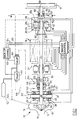
- Figure 1 is a schematic representation of a turbomachine including an active magnetic bearing arrangement in accordance with the present invention illustrating both magnetic radial, or journal, bearings and magnetic axial, or thrust, bearings and, alongside each, back-up bearing means therefor,
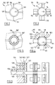
- Figure 2 is a fragmentary cross-sectional view along the line I-I of Figure 1 showing the first form of implementation of the hydrostatic back-up journal bearing means associated with the journal bearing, and
- Figure 3 is a cross-sectional view similar to Figure 2 but showing a second form of implementation of the hydrostatic back-up journal bearing means associated with the journal,
- Figure 4 is a cross-sectional view similar to Figure 3 but showing a third form of implementation of the hydrostatic back-up journal bearing means associated with the journal bearing,
- Figure 5 is a cross-sectional view similar to Figure 2 but showing a fourth form of implementation of the hydrostatic back-up journal bearing means associated with the journal bearing, and
- Figure 6 is a sectional view elevation of part of a machine similar to that of Figure 1 but showing a second form of implementation of the back-up bearing means associated with both the journal bearing and an axial thrust bearing,
- Referring to Figure 1, a
turbomachine 10 includes ashaft 11 at one end of which is carried animpeller 12 disposed in ahousing 13 having an inlet duct 14 for fluid to be processed thereby and anoutlet duct 15 from which process fluid is supplied at high pressure. The shaft is suspended with respect to active magnetic bearings and may be rotated by an electric motor, indicated ghosted at 16 and having a rotor coaxial withshaft 11, or by afluid impeller 17 in receipt of fluid at elevated pressure. The driving fluid and/or the driven (compressed) fluid may be a liquid or a gas, but in practice it is more usual to find magnetic bearings in use where rotational speed of the shaft is high and the process fluid is a gas. - The nature of the machine is not directly important to an explanation of the invention and is shown and described only to such extent as is necessary in relation to the
magnetic bearings magnetic thrust bearings - The journal bearing 20 comprises a
movable armature 25 defined on, at, or in the surface of theshaft 11 and formed in conventional manner of laminations of ferromagnetic material which may form part of a magnetic circuit minimising the formation of eddy currents as the shaft rotates. Disposed adjacent the shaft is stationary armature means 26 which comprises a plurality of electromagnets arranged about the shaft, typically four at 90° intervals. Each electromagnet comprises aferromagnetic core 27, again made up of laminations, having a plurality of limbs, such as 28, extending radially inwardly and each ending in apole face 28₁, respectively, facing, and spaced slightly from, themovable armature 25 when it is disposed suspended centrally within the bearing by asuspension gap 30. The core, and typically each limb, supports anelectromagnet coil 28₂. Other electromagnets in different planes (not shown) are similar. The other journal bearing 21 is identical. Each journal bearing, and preferably each electromagnet thereof, has associated with it a displacement sensing means for providing signals representative of the separation between the movable armature and each pole face. - The magnetic thrust bearing 22 serves to "suspend" the shaft in an axial direction against an axial thrust exerted on the shaft aerodynamically, such as by the process or driving gas. It includes a movable armature in the form of radially
extensive rotor 31 carried by theshaft 11 and, facing one side of the rotor, stationary armature means comprisingelectromagnet 32 in the form of an annular ferromagnetic core encircling the shaft and including anannular groove 33 facing the rotor defining on the coreannular pole faces electromagnet coil 36, the rotor being normally suspended in an axial direction by a balancing of axial forces on the shaft with agap 37 between the rotor and each pole face. - A second magnetic thrust bearing 23 is formed by the
rotor 31 and stationary armature means comprisingelectromagnet 38, containingelectromagnet coil 39, disposed facing the opposite face of the rotor from theelectromagnet 32 and spaced from the rotor bysuspension gap 40. However, if the shaft is subjected to a continuous external axial force, such as an aerodynamic thrust acting on an impeller, then an electromagnet may be required only to one side of therotor 31 to counter this, whereas in the absence of such continuous force, electromagnets may be disposed on both sides to effect opposing forces. - In operation, the electromagnets of each journal or thrust bearing are energised differentially in order to maintain, ideally, a uniform suspension gap between each pole face and the armature in response to the sensed displacements between the moveable armature and each pole face by means of magnet control means 41 provided with radial shaft displacement signals by sensing means 42 and axial shaft displacement signals by
sensing means 43. The speed and severity of increased magnetic force between themoveable armatures - In accordance with the present invention back-up bearing means is provided taking the form of one or more hydrostatic bearings. In a first embodiment shown in Figure 1, separate hydrostatic back-up
journal bearings magnetic journal bearings shaft 11; hydrostatic back-upthrust bearings magnetic thrust bearings surfaces solid body 57 which encircles the shaft. The running surfaces are arranged to be spaced from each other to define asupport gap 58, analogous tosuspension gap 30, when theshaft 11 is within a predetermined range of operational shaft positions within the magnetic bearing. That is, displacement of the shaft from its ideal position within thesuspension gap 30 of the magnetic bearing is countered by the magnet control means 41 which restores the shaft position from within a predetermined range of shaft positions, beyond which range the control is assumed lost and the back-up bearing is operational to effect shaft support. - The
solid body 57 carrying the stationary running surfaces is dimensioned in respect of the running surface such that the support gap defined between the rotatable and running surfaces can, at least when the shaft position is at its limit of its predetermined operational range of positions, function by the supply of fluid thereto under pressure as a hydrostatic bearing. In practice the operational range of shaft positions may be so restricted that the gap in normal operational position of the shaft is capable of functioning as a hydrostatic bearing to support the shaft. - Referring also to Figure 2, the
body 57 hasfluid channels 59 extending therethrough, opening at the runningsurface 56 and connected by way offluid lines 60 and fluid valve means 61 to receive pressurised fluid from source 62 under the control of back-up control means 63. - The back-up control means is connected to the magnet control means 41 by way of
signal lines 64 to receive signals indicative of the inability of the magnetic bearing to support the shaft within said predetermined range of operational shaft positions. - Although such signals for use by the back-up control means may be derived directly from the
sensors 42 or from a completely different set (not shown), possibly associated with thesupport gap 58, to make the back-up bearing means completely independent of the magnetic bearing, and equally responsive to loss of control after it is manifested by shaft position, it will be appreciated that if loss of control is due to electrical failure of the magnetic bearing then such change of shaft position may be anticipated at the magnet control means before its inevitable occurrence. That is, by deriving the back-up control signals from the magnetic control means it may be possible to detect an inability of the magnetic bearing to support the shaft within said predetermined range of operational shaft positions other than by direct measurement resulting from displacement. - In operation of the magnetic bearing arrangement, in response to a detected inability of the
magnetic bearing 20, or possibly any bearing at all, to support the shaft in the said predetermined range of operational shaft positions, the back-up control means opens the valve means 61 to supply fluid by way of theducts 59 to thesupport gap 58 to form therein a fluid film of such hydrostatic pressure as to then support theshaft running surface 55 clear of thestationary running surface 56, that is, support the shaft within said predetermined range of operational shaft positions. - As indicated above, it is usual for the predetermined range of operational shaft positions to be small and for the gap between the running surfaces of the back-up bearings to be small so that a complete annular fluid film may be formed and the load of the shaft taken by the hydrostatic pressure maintained throughout the film at any time and irrespective of direction of shaft displacements.
- Furthermore, the support pressure will be self-regulating in that any localised variations in shaft load on the fluid film due to external forces serves only to restrict any fluid leakage at that point and thus to increase the pressure of the supporting film.
- It will be appreciated that even if such hydrostatic fluid film is not continuous about the shaft but exists at load bearing sites distributed about the shaft then if the fluid is supplied concurrently to all running surfaces the same self-regulating effect occurs.
- Referring now to Figure 3, this shows at 70 in a cross-sectional view similar to Figure 2, a modified form of the hydrostatic back-up journal bearing 50 of that Figure. The
bearing 70 comprises the same runningsurface 55 ofshaft 11 and a plurality of stationary running surfaces 71-74 each formed on one of a plurality of blocks 75-78 respectively arrayed about the shaft. Each of the blocks has achannel 79, corresponding to 59 extending therethrough and opening to its running face, each channel being coupled to the valve means 61 for the supply of fluid thereto in order to develop a hydrostatic back-up bearing of four regions or pads of support gap. - Figure 4 shows at 90 a cross-sectional view, similar to that of Figures 2 and 3, of a third form of hydrostatic back-up journal bearing which is a modification of the
bearing 70. In this arrangement the bearing again comprises a plurality of blocks arrayed about the runningsurface 55 ofshaft 11, the blocks 91-94 optionally containing through-channels, such as 91', for the supply of fluid to the support gap, and bridging pieces 95-98, each of which provides a stationary running surface, intermediate said blocks and which optionally extend between the adjacent blocks to effect with the blocks a stationary running surface completely encircling the shaft. Some or all of the bridging pieces 95-98 are provided with a through-channel, such as 99-102 respectively, connected also to the valve means 61 and by way of which fluid is delivered to the support gap to form a hydrostatic fluid film capable of supporting the shaft. - In a modification of the above, and shown by
broken lines 103, the individual blocks 91-94 may be joined radially outwardly of the bridging pieces 99-102 to define between each pair of blocks aplenum chamber 104 to which fluid may be supplied by individual fluid lines from the valve means 61 and then by way of apertures in, or between, bridging pieces to the support gap giving a more uniform distribution of supply. Channels (not shown) provided through or in the running surfaces of said blocks may likewise communicate with such plenum chambers. - It will be appreciated that in general with any of the above described embodiments, although such separate channels may be provided with fluid in common, the valve means 61 may also be arranged to control the supply of fluid to plural channels arrayed about the shaft individually in accordance with determination, from the sensing means 42 or its equivalent, of the direction of change of shaft positions within the suspension gap such that the hydrostatic pressure maintained in respect of the fluid supplied by way of the channels is increased when it acts to overcome a specific directional loading of the shaft.
- Notwithstanding the precise constructional detail of the hydrostatic back-up bearing, its hydrostatic nature means that the shaft is supported by the fluid pressure irrespective of shaft speed, and so is able to function at all speeds down to, and including zero, that is, is able to support the shaft as the machine is run down to rest.
- It may be preferred, however, to supplement the hydrostatic function of the back-up bearing with contact-making running surfaces which are caused to be effective at very low speeds approaching rest and at rest by controlled reduction in hydrostatic pressure. To this end, and as shown in the cross-sectional elevation of Figure 5, which corresponds in most respect of Figure 2, one or both the running surfaces 55' and 56' are formed of a hardened and/or low friction material such that they can run at said low speeds to rest in contact. Indeed such friction as inevitably occurs with such contact may be employed to effect a braking action. Whereas such contact between running surfaces is effected by controlled reduction in hydrostatic pressure, fluid may still be provided at insufficient pressure to effect bearing action but to effect, by leakage thereof, a fluid flow to extract heat from the running surfaces. In this respect the ability to provide such heat extraction, and possibly a degree of lubrication in dependence on the fluid, gives a wider range of suitable running surface materials.
- The stationary running surface 56' may be formed as a coating on the surface of the block (or corresponding bridging pieces in the embodiments of Figures 3 to 4) or by forming the block of such material, the choices of material being dependant upon the fluid employed.
- To the extent necessary for general implementation of the invention, the nature of the fluid is a matter for choice and may be either a liquid or a gas.
- Preferably the fluid is a gas and gases are well studied and known for use in hydrostatic, or more precisely, aerostatic bearings. Preferably the gas is plentiful, such as air, although it may also be required to be inert. It may also be possible to employ the motive power of, or process gas of, a turbomachine, where such gas is suitable, as indicated by the broken lines 62' in place of the source 62 extending from the
housing 13 to the back-up valve means 61. - However, it may be expected that gas, whilst providing heat extraction from running surfaces enabled to contact, may also be expected to provide less lubrication than a liquid and for the surfaces to effect dry running.
- The above described embodiments have concentrated on presenting the invention with reference to the single hydrostatic back-up
bearing 50. It will be understood that the hydrostatic back-upbearing 51 is identical in construction, being connected also to the back-up valve means 61 to receive fluid therefrom in response to detected inability of themagnetic bearing 21 individually, or possibly any magnetic bearing, to support the shaft. - The
magnetic thrust bearings - In the
bearing 52, for example, arotor 110 affixed toshaft 11 extends radially therefrom and one radial face forms arotatable running surface 111 axially spaced therefrom is a suitable radially extending annularstationary running surface 112, the separation between them, when the shaft is supported axially at an ideal position, comprises supportinggap 113 defining one limit of the predetermined range of operational axial positions permitted of the shaft before the back-up bearing means functions axially. - The
stationary running surface 112 may encircle the shaft completely, analogously to the journal bearing runningsurface 56 of Figure 2, or may be intermittent, that is, comprise individual bearing pads, analogously to the journal bearing means surfaces 71-74 of Figure 3. - In the case of a continuous running surface, this is formed on annular block 114 through which extend a plurality of fluid channels 115 opening into the running
face 112, the channels being connected byfluid lines 116 to back-up valve means 117, like valve means 61, supplied with fluid by source 62 (or process gas from 13) and controlled by back-up control means 63. - As described above in respect of the journal bearing 50 and with reference to Figures 2 to 5, the fluid channels 115 may pass through bridging pieces, possibly defining plenum chambers, between segmented bearing blocks as well as, or instead of, through the blocks, and furthermore the running
surfaces - The hydrostatic back-up thrust bearing 53 is formed likewise, the rotatable running surface conveniently being formed on the other radial face of
rotor 110, and coupled byfluid lines 116 to the back-up valve means 117. - As stated above with respect to the back-up hydrostatic journal bearing 50, the operation of the back-up
bearings suspension gaps support gaps 113 of the back-up thrust bearings and feed the back-up control means 63 directly, and furthermore separate back-up control means (not shown) corresponding to 63 may be dedicated to the thrust back-upbearings bearings - It will be understood that whereas in respect of a hydrostatic back-up bearing it may not matter in which direction shaft displacement occurs to take it to the limit of its predetermined operational range, in the case of a thrust bearing it may be more significant.
- In an arrangement, such as shown in Figure 1, wherein the shaft is suspended axially by the opposing attractions of the electromagnets of the
thrust bearing bearings - As indicated hereinbefore, the machine arrangement similar to Figure 1 may have only one magnetic thrust bearing which applies an axially directed magnetic attraction force to the shaft in opposition to an externally applied thrust. Clearly the possibility arises not only of an increase in axial thrust in one direction displacing the rotor towards the thrust bearing electromagnet but also of a decrease in force or electromagnet failure resulting in the shaft being displaced oppositely. Accordingly, hydrostatic back-up bearing means in respect of single electromagnetic thrust bearing preferably still comprises a pair of such bearings as illustrated by 52 and 53, even though the back-up control may energise only one of them at a time in dependence of the shaft displacement and/or its cause. In the event of electromagnet failure and running down of the shaft speed to zero, which may affect any aerodynamically induced axial thrust on the shaft the back-up control means may energise both back-up thrust bearings for stability.
- It will be appreciated that other variations of design may be incorporated instead of, or in addition to, those outlined above and within the ambit of the present invention as defined in the claims.
- For example, and as illustrated in Figure 6, the stationary running surfaces 120 and 121 of both journal and thrust hydrostatic back-up
bearings single body 124 which may itself be composed of a suitable dry running self lubricating bearing material, such as that produced by Glacier GmbH-Deva Werke and sold under the Registered Trade Mark DEVA, designed to run at least at low shaft speeds in contact with an L-section sleeve 125 of hardened material carried byshaft 11 and providing both journal and thrustrotor running surfaces - The block 24 encircles the shaft and has therethrough
fluid channels 128 for supplying fluid to (as appropriate) the stationary running faces 120, 121 under the control of back-up control means (not shown). To prevent leakage of fluid from the support gaps of either individual bearings interfering with the hydrostatic film of the other bearing means, in the form of adrain channel 130, is provided through the block and opening to the interface between the two stationary running surfaces. Preferably the fluid is a gas and preferably, if pressure is reduced to permit contact of running surfaces, a flow is maintained to extract heat therefrom and protect the surface of theblock 124. Clearly only one such combination is shown in Figure 6 and others may be provided as needed. - The above described embodiments have all related to the provision of back-up bearing arrangements for electromagnetic bearings wherein inability of the bearing arrangement to suspend the shaft within a predetermined range of operational shaft positions is readily (although not necessarily) determined by the electromagnetic bearing control means, or at least position sensing means associated therewith.
- It will be appreciated that back-up bearing means may be provided in a similar manner for a passive magnetic bearing, notwithstanding the possible requirement for specific position sensing means corresponding to 42 and/or 43 of Figure 1 for providing signals to back-up control means corresponding to 63. Of course in such a passive bearing there are no electromagnetic coils to benefit from a cooling flow of the back-up bearing fluid or be a cause of bearing failure, but in other respects operation and effect are analogous.
Claims (11)
- A magnetic bearing arrangement for a rotatable shaft (11) including a magnetic bearing (20,21,22,23), and back-up bearing means having adjacently disposed rotatable (55, 111,126,127) and stationary (56,112,71-74,120,121) running surfaces spaced from each other to define a support gap (58,113) when the shaft is within a predetermined range of operational shaft positions within said magnetic bearing, a source of pressurised fluid (62) and back-up control means (63) responsive to a detected inability of the magnetic bearing to support said shaft within said predetermined range of operational shaft positions, and characterised in that the back-up bearing means comprises a hydrostatic bearing (50,51,52,53) in which said stationary running surface includes a plurality of apertures (59,79,91') arrayed about the axis of the shaft and arranged to admit fluid from said source at such pressure as to provide between the running surfaces hydrostatic pressure of fluid to support them spaced from each other independently of relative rotational motion between them.
- A magnetic bearing arrangement as claimed in claim 1 characterised in that the hydrostatic bearing means (50,51,52,53) is arranged by way of said back-up control means (63) to support the shaft (11) within said predetermined range of operational shaft positions at all rotational speeds of the shaft.
- A magnetic bearing arrangement as claimed in claim 1 characterised in that, in operation of said back-up bearing means, said back-up control means (63) is arranged at low shaft speeds not to provide fluid to the hydrostatic bearing at such pressure to effect support of the shaft such that said adjacently disposed running surfaces (55',56';126,120; 127,121) are arranged to run in contact.
- A magnetic bearing arrangement as claimed in claim 3 characterised in that the back-up control means (63) is arranged at low shaft speeds to provide fluid to the hydrostatic bearing at such pressure as to effect fluid flow at the contacting running surfaces to extract heat therefrom.
- A magnetic bearing arrangement as claimed in any one of the preceding claims characterised in that a said stationary running surface of the back-up bearing means comprises a surface of a solid body (57,75-78,124) through which extends a fluid channel (59,79, 91',128) opening to said running surface (56,71-74, 120,121).
- A magnetic bearing arrangement as claimed in claim 5 characterised in that the solid body (124) comprises a block of low-friction dry-running bearing material.
- A magnetic bearing arrangement as claimed in claim 6 characterised in that the solid body (124) comprises a block of porous metal loaded with a dry lubricant material.
- A magnetic bearing arrangement as claimed in any one of claims 5 to 7 characterised in that the solid body (124) carries a stationary running surface (120) of a radial journal bearing and a stationary running surface (121) of an axial thrust bearing, each running surface having a fluid channel (128) associated therewith and, between said stationary running surface, means (130) to prevent fluid leakage from one bearing interfering with operation of the other.
- A magnetic bearing arrangement as claimed in claim 8 characterised in that said means to prevent fluid leakage from one bearing from interfering with operation of the other comprises at least one drain channel (130) extending through said solid body and opening to an interface between the running surfaces of said radial and axial bearings defined by the body.
- A magnetic bearing arrangement as claimed in claim 1 characterised in that said hydrostatic fluid is a gas.
- A turbomachine operable (10) to process gas at elevated pressure including a magnetic bearing as claimed in claim 10 in which said back-up bearing means fluid gas is derived (62') at least in part from said process gas.
Applications Claiming Priority (2)
| Application Number | Priority Date | Filing Date | Title |
|---|---|---|---|
| GB9215620A GB2268983B (en) | 1992-07-23 | 1992-07-23 | Magnetic bearing back-up |
| GB9215620 | 1992-07-23 |
Publications (2)
| Publication Number | Publication Date |
|---|---|
| EP0580202A1 EP0580202A1 (en) | 1994-01-26 |
| EP0580202B1 true EP0580202B1 (en) | 1996-04-17 |
Family
ID=10719139
Family Applications (1)
| Application Number | Title | Priority Date | Filing Date |
|---|---|---|---|
| EP93201916A Expired - Lifetime EP0580202B1 (en) | 1992-07-23 | 1993-07-01 | Magnetic bearing back-up |
Country Status (5)
| Country | Link |
|---|---|
| US (1) | US5345127A (en) |
| EP (1) | EP0580202B1 (en) |
| JP (1) | JP3686093B2 (en) |
| DE (1) | DE69302235T2 (en) |
| GB (1) | GB2268983B (en) |
Families Citing this family (32)
| Publication number | Priority date | Publication date | Assignee | Title |
|---|---|---|---|---|
| US6310414B1 (en) * | 1994-06-21 | 2001-10-30 | Rotoflow Corporation | Shaft bearing system |
| US5635784A (en) * | 1995-02-13 | 1997-06-03 | Seale; Joseph B. | Bearingless ultrasound-sweep rotor |
| JP3696398B2 (en) * | 1997-04-28 | 2005-09-14 | Ntn株式会社 | Hydrostatic magnetic compound bearing and spindle device |
| GB9904221D0 (en) * | 1999-02-25 | 1999-04-21 | Rolls Royce Plc | Gas turbine engine bearing arrangement |
| US6508614B1 (en) * | 1999-03-17 | 2003-01-21 | Ntn Corporation | Spindle device and machine tool utilizing the same |
| SE515173C2 (en) * | 1999-11-10 | 2001-06-25 | Skf Nova Ab | Device at a tool carrying unit for moving a rotatable shaft in the axial direction |
| WO2002099294A2 (en) | 2001-06-06 | 2002-12-12 | Delaware Capital Formation Inc | Journal bearing arrangement |
| EP1792093A4 (en) * | 2004-06-15 | 2011-10-26 | Aly El-Shafei | Methods of controlling the instability in fluid film bearings |
| KR101118799B1 (en) * | 2004-07-02 | 2012-03-20 | 싸우에르 게엠바하 | Tool with an oscillating head |
| TW201107639A (en) * | 2007-04-27 | 2011-03-01 | Edwards Japan Ltd | Plate rotating device, exhaust path opening degree changing device, exhausted device, transfer device, beam device, and gate valve |
| DE102007059467B4 (en) * | 2007-12-11 | 2010-06-02 | Minebea Co., Ltd. | Magnetic thrust bearing |
| US8212444B2 (en) | 2007-12-11 | 2012-07-03 | Minebea Co., Ltd. | Magnetic axial bearing and a spindle motor having this kind of magnetic axial bearing |
| DE102008046219A1 (en) * | 2008-09-08 | 2010-03-11 | Bosch Mahle Turbo Systems Gmbh & Co. Kg | Exhaust gas turbocharger for use in airplane, has rotor arranged at rotor axle, which is inclined with respect to horizontal plane at inclination angle, where inclination angle is of specific range |
| DE102008046636B4 (en) * | 2008-09-09 | 2014-04-03 | Fraunhofer-Gesellschaft zur Förderung der angewandten Forschung e.V. | Aerostatic bearing assembly with associated electrostatic biasing unit, especially for vacuum application |
| ES2388189T3 (en) | 2008-09-25 | 2012-10-10 | Siemens Aktiengesellschaft | Steam turbine |
| DE102008062679A1 (en) * | 2008-12-17 | 2010-06-24 | Minebea Co., Ltd. | Fluid dynamic storage system |
| US20110052109A1 (en) * | 2009-08-28 | 2011-03-03 | Dresser-Rand Company | Hydrostatic auxiliary bearing for a turbomachine |
| US8651747B2 (en) | 2010-10-28 | 2014-02-18 | Dresser-Rand Company | Planetary-type auxiliary bearing |
| US8994237B2 (en) | 2010-12-30 | 2015-03-31 | Dresser-Rand Company | Method for on-line detection of liquid and potential for the occurrence of resistance to ground faults in active magnetic bearing systems |
| EP2659277B8 (en) | 2010-12-30 | 2018-05-23 | Dresser-Rand Company | Method for on-line detection of resistance-to-ground faults in active magnetic bearing systems |
| WO2012138545A2 (en) | 2011-04-08 | 2012-10-11 | Dresser-Rand Company | Circulating dielectric oil cooling system for canned bearings and canned electronics |
| US8876389B2 (en) | 2011-05-27 | 2014-11-04 | Dresser-Rand Company | Segmented coast-down bearing for magnetic bearing systems |
| US8851756B2 (en) | 2011-06-29 | 2014-10-07 | Dresser-Rand Company | Whirl inhibiting coast-down bearing for magnetic bearing systems |
| JP2015533410A (en) * | 2012-11-08 | 2015-11-24 | ワウケシャ ベアリングズ コーポレーションWaukesha Bearings Corporation | Hybrid bearing |
| US9212665B2 (en) * | 2013-04-08 | 2015-12-15 | Dresser-Rand Company | Planetary-type auxiliary bearing for a hydrostatic primary bearing |
| KR102613952B1 (en) * | 2016-07-25 | 2023-12-15 | 엘지전자 주식회사 | Center error value of bearings measuring method |
| US10634154B2 (en) * | 2016-07-25 | 2020-04-28 | Daikin Applied Americas Inc. | Centrifugal compressor and magnetic bearing backup system for centrifugal compressor |
| CN107100930B (en) * | 2017-04-21 | 2019-02-22 | 燕山大学 | A kind of electromagnetism-static pressure dual suspension thrust bearing |
| KR102383011B1 (en) * | 2017-09-20 | 2022-04-04 | 한화파워시스템 주식회사 | Magnetic damper system applied to dry gas seal |
| GB201718068D0 (en) * | 2017-11-01 | 2017-12-13 | Rolls Royce Plc | Resonance vibration control method and system |
| TWI696761B (en) * | 2018-11-14 | 2020-06-21 | 財團法人工業技術研究院 | Magnetic bearing centrifugal compressor and controlling method thereof |
| CN110925303A (en) * | 2019-12-23 | 2020-03-27 | 至玥腾风科技集团有限公司 | Combined bearing |
Family Cites Families (7)
| Publication number | Priority date | Publication date | Assignee | Title |
|---|---|---|---|---|
| FR2613791B1 (en) * | 1987-04-09 | 1992-03-13 | Europ Propulsion | RADIAL MAGNETIC BEARING WITH EMERGENCY LANDING AND APPLICATION TO AN ACTIVE MAGNETIC SUSPENSION TURBOMACHINE |
| FR2630792B1 (en) * | 1988-04-29 | 1992-03-06 | Mecanique Magnetique Sa | AUXILIARY BEARING WITH GRAPHITE STATOR FOR ROTATING SHAFT MOUNTED ON MAGNETIC BEARINGS |
| JPH0674809B2 (en) * | 1989-04-13 | 1994-09-21 | いすゞ自動車株式会社 | Bearing device for high-speed rotating shaft |
| GB2234560B (en) * | 1989-08-04 | 1993-08-18 | Glacier Metal Co Ltd | A magnetic bearing shaft assembly having a bearing to support the shaft in the event of failure of the magnetic bearing |
| US5059845A (en) * | 1990-05-07 | 1991-10-22 | Mechanical Technology Incorporated | Active magnetic bearing device for controlling rotor vibrations |
| DE9112813U1 (en) * | 1990-11-09 | 1991-12-05 | Siemens Ag, 8000 Muenchen, De | |
| US5126641A (en) * | 1991-03-08 | 1992-06-30 | Westinghouse Electric Corp. | Bidirectional variable reluctance actuator and system for active attenuation of vibration and structure borne noise utilizing same |
-
1992
- 1992-07-23 GB GB9215620A patent/GB2268983B/en not_active Expired - Fee Related
-
1993
- 1993-07-01 EP EP93201916A patent/EP0580202B1/en not_active Expired - Lifetime
- 1993-07-01 DE DE69302235T patent/DE69302235T2/en not_active Expired - Fee Related
- 1993-07-14 US US08/091,184 patent/US5345127A/en not_active Expired - Lifetime
- 1993-07-22 JP JP18110493A patent/JP3686093B2/en not_active Expired - Lifetime
Also Published As
| Publication number | Publication date |
|---|---|
| EP0580202A1 (en) | 1994-01-26 |
| JP3686093B2 (en) | 2005-08-24 |
| US5345127A (en) | 1994-09-06 |
| DE69302235T2 (en) | 1996-11-28 |
| JPH06159362A (en) | 1994-06-07 |
| GB2268983B (en) | 1996-04-03 |
| DE69302235D1 (en) | 1996-05-23 |
| GB2268983A (en) | 1994-01-26 |
| GB9215620D0 (en) | 1992-09-09 |
Similar Documents
| Publication | Publication Date | Title |
|---|---|---|
| EP0580202B1 (en) | Magnetic bearing back-up | |
| EP0580201B1 (en) | Magnetic bearing back-up | |
| US5137286A (en) | Permanent magnet floating shaft seal | |
| US5791868A (en) | Thrust load compensating system for a compliant foil hydrodynamic fluid film thrust bearing | |
| US5064205A (en) | Active magnetic seal | |
| US5767597A (en) | Electromagnetically biased homopolar magnetic bearing | |
| US6310414B1 (en) | Shaft bearing system | |
| US6255752B1 (en) | Mounting for a turbo-machine rotor and its use | |
| US5836739A (en) | Gas turbine engine | |
| Habermann et al. | An active magnetic bearing system | |
| CA2382478C (en) | A seal assembly | |
| US20030038553A1 (en) | Permanent magnet turbo-generator having magnetic bearings | |
| MX2013011852A (en) | Air gap control systems and methods. | |
| JPH056017B2 (en) | ||
| GB2272050A (en) | Air cycle machine with electro-magnetic bearings | |
| CZ293543B6 (en) | Rotary dynamic machine for conveying a fluid and device for controlling thereof | |
| GB2298901A (en) | Gas turbine engine axial thrust balancing | |
| JPH0469308B2 (en) | ||
| CA2310191A1 (en) | Mounting of rotors of generators in a magnetic field | |
| CA2192475A1 (en) | Dc-biased axial magnetic bearing | |
| JP3733160B2 (en) | Magnetic bearing device | |
| RU225202U1 (en) | Radial active magnetic bearing | |
| Weise | Present industrial applications of active magnetic bearings | |
| JPH10292818A (en) | High-speed rotating machine | |
| JPH09257034A (en) | Fluid machine having magnetic bearing and hydrostatic bearing |
Legal Events
| Date | Code | Title | Description |
|---|---|---|---|
| PUAI | Public reference made under article 153(3) epc to a published international application that has entered the european phase |
Free format text: ORIGINAL CODE: 0009012 |
|
| AK | Designated contracting states |
Kind code of ref document: A1 Designated state(s): CH DE FR IT LI SE |
|
| 17P | Request for examination filed |
Effective date: 19940629 |
|
| 17Q | First examination report despatched |
Effective date: 19950316 |
|
| GRAH | Despatch of communication of intention to grant a patent |
Free format text: ORIGINAL CODE: EPIDOS IGRA |
|
| GRAA | (expected) grant |
Free format text: ORIGINAL CODE: 0009210 |
|
| ITF | It: translation for a ep patent filed |
Owner name: BARZANO' E ZANARDO ROMA S.P.A. |
|
| AK | Designated contracting states |
Kind code of ref document: B1 Designated state(s): CH DE FR IT LI SE |
|
| REG | Reference to a national code |
Ref country code: CH Ref legal event code: NV Representative=s name: KIRKER & CIE SA |
|
| REF | Corresponds to: |
Ref document number: 69302235 Country of ref document: DE Date of ref document: 19960523 |
|
| ET | Fr: translation filed | ||
| PLBE | No opposition filed within time limit |
Free format text: ORIGINAL CODE: 0009261 |
|
| STAA | Information on the status of an ep patent application or granted ep patent |
Free format text: STATUS: NO OPPOSITION FILED WITHIN TIME LIMIT |
|
| 26N | No opposition filed | ||
| REG | Reference to a national code |
Ref country code: CH Ref legal event code: PUE Owner name: FEDERAL-MOGUL ENGINEERING LIMITED TRANSFER- DELAWA Ref country code: CH Ref legal event code: PFA Free format text: THE GLACIER METAL COMPANY LIMITED TRANSFER- FEDERAL-MOGUL ENGINEERING LIMITED |
|
| REG | Reference to a national code |
Ref country code: FR Ref legal event code: TP Ref country code: FR Ref legal event code: CD Ref country code: FR Ref legal event code: CA |
|
| PGFP | Annual fee paid to national office [announced via postgrant information from national office to epo] |
Ref country code: CH Payment date: 20040611 Year of fee payment: 12 |
|
| PG25 | Lapsed in a contracting state [announced via postgrant information from national office to epo] |
Ref country code: IT Free format text: LAPSE BECAUSE OF NON-PAYMENT OF DUE FEES;WARNING: LAPSES OF ITALIAN PATENTS WITH EFFECTIVE DATE BEFORE 2007 MAY HAVE OCCURRED AT ANY TIME BEFORE 2007. THE CORRECT EFFECTIVE DATE MAY BE DIFFERENT FROM THE ONE RECORDED. Effective date: 20050701 |
|
| PG25 | Lapsed in a contracting state [announced via postgrant information from national office to epo] |
Ref country code: LI Free format text: LAPSE BECAUSE OF NON-PAYMENT OF DUE FEES Effective date: 20050731 Ref country code: CH Free format text: LAPSE BECAUSE OF NON-PAYMENT OF DUE FEES Effective date: 20050731 |
|
| REG | Reference to a national code |
Ref country code: CH Ref legal event code: PL |
|
| PGFP | Annual fee paid to national office [announced via postgrant information from national office to epo] |
Ref country code: FR Payment date: 20090716 Year of fee payment: 17 |
|
| PGFP | Annual fee paid to national office [announced via postgrant information from national office to epo] |
Ref country code: SE Payment date: 20090715 Year of fee payment: 17 Ref country code: DE Payment date: 20090722 Year of fee payment: 17 |
|
| REG | Reference to a national code |
Ref country code: FR Ref legal event code: ST Effective date: 20110331 |
|
| PG25 | Lapsed in a contracting state [announced via postgrant information from national office to epo] |
Ref country code: DE Free format text: LAPSE BECAUSE OF NON-PAYMENT OF DUE FEES Effective date: 20110201 |
|
| REG | Reference to a national code |
Ref country code: DE Ref legal event code: R119 Ref document number: 69302235 Country of ref document: DE Effective date: 20110201 |
|
| PG25 | Lapsed in a contracting state [announced via postgrant information from national office to epo] |
Ref country code: FR Free format text: LAPSE BECAUSE OF NON-PAYMENT OF DUE FEES Effective date: 20100802 |
|
| PG25 | Lapsed in a contracting state [announced via postgrant information from national office to epo] |
Ref country code: SE Free format text: LAPSE BECAUSE OF NON-PAYMENT OF DUE FEES Effective date: 20100702 |