EP0587467A1 - Dispositif de projection électrostatique de produit de revêtement électriquement conducteur, muni d'un réservoir isolé adapté à contenir un tel produit - Google Patents
Dispositif de projection électrostatique de produit de revêtement électriquement conducteur, muni d'un réservoir isolé adapté à contenir un tel produit Download PDFInfo
- Publication number
- EP0587467A1 EP0587467A1 EP93401996A EP93401996A EP0587467A1 EP 0587467 A1 EP0587467 A1 EP 0587467A1 EP 93401996 A EP93401996 A EP 93401996A EP 93401996 A EP93401996 A EP 93401996A EP 0587467 A1 EP0587467 A1 EP 0587467A1
- Authority
- EP
- European Patent Office
- Prior art keywords
- cavity
- piston
- coating product
- bottom wall
- jacket
- Prior art date
- Legal status (The legal status is an assumption and is not a legal conclusion. Google has not performed a legal analysis and makes no representation as to the accuracy of the status listed.)
- Granted
Links
Images

Classifications
-
- B—PERFORMING OPERATIONS; TRANSPORTING
- B05—SPRAYING OR ATOMISING IN GENERAL; APPLYING FLUENT MATERIALS TO SURFACES, IN GENERAL
- B05B—SPRAYING APPARATUS; ATOMISING APPARATUS; NOZZLES
- B05B5/00—Electrostatic spraying apparatus; Spraying apparatus with means for charging the spray electrically; Apparatus for spraying liquids or other fluent materials by other electric means
- B05B5/16—Arrangements for supplying liquids or other fluent material
- B05B5/1608—Arrangements for supplying liquids or other fluent material the liquid or other fluent material being electrically conductive
- B05B5/1675—Arrangements for supplying liquids or other fluent material the liquid or other fluent material being electrically conductive the supply means comprising a piston, e.g. a piston pump
-
- B—PERFORMING OPERATIONS; TRANSPORTING
- B05—SPRAYING OR ATOMISING IN GENERAL; APPLYING FLUENT MATERIALS TO SURFACES, IN GENERAL
- B05B—SPRAYING APPARATUS; ATOMISING APPARATUS; NOZZLES
- B05B5/00—Electrostatic spraying apparatus; Spraying apparatus with means for charging the spray electrically; Apparatus for spraying liquids or other fluent materials by other electric means
- B05B5/16—Arrangements for supplying liquids or other fluent material
- B05B5/1608—Arrangements for supplying liquids or other fluent material the liquid or other fluent material being electrically conductive
-
- B—PERFORMING OPERATIONS; TRANSPORTING
- B05—SPRAYING OR ATOMISING IN GENERAL; APPLYING FLUENT MATERIALS TO SURFACES, IN GENERAL
- B05B—SPRAYING APPARATUS; ATOMISING APPARATUS; NOZZLES
- B05B13/00—Machines or plants for applying liquids or other fluent materials to surfaces of objects or other work by spraying, not covered by groups B05B1/00 - B05B11/00
- B05B13/02—Means for supporting work; Arrangement or mounting of spray heads; Adaptation or arrangement of means for feeding work
- B05B13/04—Means for supporting work; Arrangement or mounting of spray heads; Adaptation or arrangement of means for feeding work the spray heads being moved during spraying operation
- B05B13/0431—Means for supporting work; Arrangement or mounting of spray heads; Adaptation or arrangement of means for feeding work the spray heads being moved during spraying operation with spray heads moved by robots or articulated arms, e.g. for applying liquid or other fluent material to 3D-surfaces
-
- B—PERFORMING OPERATIONS; TRANSPORTING
- B05—SPRAYING OR ATOMISING IN GENERAL; APPLYING FLUENT MATERIALS TO SURFACES, IN GENERAL
- B05B—SPRAYING APPARATUS; ATOMISING APPARATUS; NOZZLES
- B05B13/00—Machines or plants for applying liquids or other fluent materials to surfaces of objects or other work by spraying, not covered by groups B05B1/00 - B05B11/00
- B05B13/02—Means for supporting work; Arrangement or mounting of spray heads; Adaptation or arrangement of means for feeding work
- B05B13/04—Means for supporting work; Arrangement or mounting of spray heads; Adaptation or arrangement of means for feeding work the spray heads being moved during spraying operation
- B05B13/0447—Installation or apparatus for applying liquid or other fluent material to conveyed separate articles
- B05B13/0452—Installation or apparatus for applying liquid or other fluent material to conveyed separate articles the conveyed articles being vehicle bodies
Definitions
- the invention relates to a device for electrostatic projection of an electrically conductive liquid coating product, such as a water-based paint. It relates more particularly to a compact and light unit comprising in particular a reservoir of such a product normally brought to high voltage during a projection phase, the unit being capable of preventing the establishment of any ramping current between a part at the high voltage and any other part maintained by construction at a different potential, typically the potential of the earth.
- the invention relates more particularly but not exclusively to a unit incorporating such an intermediate reservoir and at least one electrostatic projector, which is sufficiently compact and light to be carried by the end of a multi-axis robot including, in particular, the various segments articulated to each other are at the potential of the earth.
- the patent FR 2 609 252 describes, among other things, a system for electrostatic projection of conductive coating product remarkable in that the quantity of product necessary for painting an object, is stored in a tank carried by a multi-axis robot.
- the latter also carries the electrostatic headlamp, which is located in the immediate vicinity of the tank.
- it can also carry at least the high voltage part of the electrical supply.
- the high voltage output of this supply is connected to the projector so that all of the conductive coating product contained in the tank is itself brought to high voltage.
- Such a system has in particular two important advantages. It eliminates any long flexible hose between the coating products distribution circuit and the projector carried by the robot, which saves significant amounts of coating product with each change of coating product, that is to say in fact with each change of color. It also makes it possible to carry out simply the necessary galvanic isolation between the tank and the supply circuit (at ground potential) during each spraying phase, when the coating product is a conductive product applied electrostatically.
- the invention relates first of all to a compact and light arrangement of such an insulated intermediate tank, capable of containing a conductive coating product brought to a high voltage.
- the device which is the subject of the invention is notably remarkable for all the measures taken to avoid the formation of leakage currents resulting from so-called "creeping" phenomena along in principle insulating surfaces, extending between an element brought to the high voltage and any element brought to a different potential, in particular the earth potential.
- the invention therefore relates to a device for electrostatic projection of an electrically conductive liquid coating product, of the type comprising a reservoir of such a product where it is brought to a high voltage, defined in a generally cylindrical cavity formed in a body made of insulating material and inside which there is a piston forming in said cavity a movable wall separating a coating product chamber from an actuation chamber filled with an electrically insulating actuating fluid, said body being fixed to a base of conductive material brought to earth potential to which is connected, in particular, an actuating fluid supply circuit which extends between said base and said actuation chamber and opens into the latter in the vicinity of the bottom wall of said cavity which is not in contact with said coating product, characterized in that a section of said supply circuit e st arranged substantially parallel to said cavity in the opposite direction of said base from said bottom wall.
- the entire cavity (up to the bottom wall of the actuation chamber) is at high voltage at least when the piston is pushed back in contact with this bottom wall, c that is to say when the tank is filled with coating product.
- Said actuating fluid supply circuit necessarily opens into the actuating chamber and could therefore therefore constitute a privileged path for the appearance of a possible ramping current.
- the invention makes it possible to guarantee a "path" of sufficient length along the insulating surfaces of this actuating fluid supply circuit from the actuating chamber to avoid the occurrence of ramping currents.
- a shielded component may consist of a resistive sensor (of the potentiometer type) intended to determine the location of the piston and follow its movements to control the flow rate of coating product and to know, at any time, the quantity of product contained in the tank.
- the length of the "path" defined above is obviously a function of the value of the high voltage.
- the bottom wall and at least the largest part of the cylindrical wall of the cavity are defined in the same block of said body.
- the electrostatic projection device as shown here comprises a multi-axis robot 11, known per se, of which there has been shown, in phantom, only the end portion to which is fixed in cantilever, a sub- assembly 12 comprising a reservoir 13 provided internally with a piston 14, an electrostatic sprayer 15 of coating product, connected to be supplied by the reservoir, a high voltage generator 16 and a connection unit 17 provided with connectors and pneumovannes, for connection to a cleaning installation and supply of the chosen coating product, this installation not being shown.
- the structure of the connection unit is not part of the invention and will therefore not be described in detail.
- the reservoir is defined in a generally cylindrical cavity 20 formed in a body 22 of insulating material, which consists of the assembly of two blocks, a first block 23 in which the major part of the reservoir is defined and which is fixed to a metal base 24 carried by the end of the robot 11 and a second block 25, carrying in particular the projector electrostatic 15, its pneumatically actuated flow regulator 28, and the aforementioned connection unit 17.
- the piston 14 forms in said cavity, a movable wall separating a coating product chamber 30 (in communication with the electrostatic headlamp and the connection unit) from an actuation chamber 32 filled with an electrically actuating fluid.
- insulator in this case air.
- An actuating fluid supply circuit 34 necessarily opens into said actuating chamber. This circuit extends between said actuation chamber and the base 24 because, in order not to impede the movements of the robot and to allow a rapid change of the sub-assembly 12, all the pneumatic supply circuits and the electric cables which there are connected, pass through this base so that the electrical and pneumatic connections are grouped in a sort of beam inside the multi-axis robot.
- the subassembly 12 is applied to the base 24 and is fixed therein by means of a threaded ring 35.
- This assembly achieves the continuity of the various pneumatic circuits and the low voltage electrical connections, here via an axial connector 36
- the entire robot, up to and including the base 24, is at ground potential.
- the body also houses another shielded component from the electrical point of view, that is to say comprising a metallic envelope intended to be connected to the earth potential and therefore capable of promoting the establishment of rampage currents.
- a resistive sensor 40 forming a sort of linear potentiometer, of known structure, capable of being actuated by means of a magnet 42 carried by the piston 14.
- It comprises a metallic casing 43, tubular electrically connected to the basement.
- a resistive sensor comprises two rectilinear tracks made of resistive material 44 a , 44 b , arranged side by side while a cursor 45 or the like consisting of or comprising an element sensitive to a magnetic field is subject to move along these two tracks parallel to the piston.
- said cursor 45 is metallic and retained in contact with the two tracks by the magnetic tensile force exerted by the magnet 42.
- this resistive sensor 40 is intended to allow the development of an electrical signal representative of the position of the piston 14 inside the tank. It could be replaced by any other means of non-contact detection of the position of the piston in the cavity.
- the invention makes it possible to take into account the additional problem created by the presence of a shielded sensor from the electrical point of view, that is to say of which the metal envelope is brought to the earth potential.
- the bottom wall 48 of the cavity which is not in contact with the coating product and at least most of the cylindrical wall 49 of this same cavity 20 are defined in the same block 23.
- the surface of this part of the cavity is continuous, without fitting or assembly and constitutes a kind of blind hole with a flat bottom.
- a section of the air supply circuit is arranged substantially parallel to this cavity in the opposite direction of said base 24 from the bottom wall 48. In this way, the distance between the bottom wall 48 and the metal base 24 can be relatively small so that the subassembly 12 mounted in overhang at the end of the robot arm, is as compact and light as possible.
- the piston 14 is slidably mounted in a tubular jacket 50 of electrically insulating material, for example ceramic, glass, or even plastic, mounted adjusted in the cavity 20 and the aforementioned section of the supply circuit 34 in actuating fluid is constituted by at least one longitudinal channel 54 defined between the surface of the cavity and the external face of the jacket.
- said tubular jacket 50 has at least one longitudinal groove 55 on its outer face, extending from the end of said jacket adjoining the bottom wall of the cavity to a circular groove 56 of connection communicating with a bore 57 of said body forming part of said actuating fluid supply circuit.
- the tubular jacket 50 comprises a plurality of longitudinal grooves 55 regularly distributed on its outer face and all communicating with said circular groove 56 for connection.
- the jacket is drilled radially or crenellated at the end of each longitudinal groove to establish communication between said grooves and the actuation chamber 48.
- the corresponding edge of the skirt of the piston 14 is also crenellated, for the same reason.
- the actuating fluid supply circuit comprises a straight pipe 58 installed longitudinally in an external cylindrical recess 59 formed over almost the entire length of the block 23 to lighten the sub-assembly 12 mounted in overhang on the robot.
- This pipe is connected, by screwed connection ends, to the bore 57 on the one hand and to the part 34a of the circuit formed in the base, on the other hand.
- the circuit 34 is itself connected to a source of compressed air supply, not shown.
- the other air circuits supplying, for example, the sprayer 15 and the regulator 28 are arranged in the same way, that is to say that they pass through the base 24 and are extended by a pipe installed in the recess 59.
- the latter is covered with a cylindrical protective sleeve 60, made of insulating material.
- a seal 62 is interposed between the two blocks of insulating material 23, 25 constituting the body 22, outside the jacket 50. Consequently, the actuating air injected at the level of the circular groove 56 does not can escape through the assembly plane of the two blocks.
- the air supply circuit d actuation 34 comprises a section of sufficient length (at least between said bottom wall 48 and the circular groove 56) so that no ramping current can be established towards any metallic element brought to earth potential.
- this section has a length of the order of 20 cm.
- a tubular guard ring 65 made of insulating material, is inserted in the two blocks 23, 25, perpendicular to their assembly surface and coaxially with the cavity 20. This arrangement is conventional for combating the currents of rampage.
- the guard ring 65 is installed between the cavity 20, on the outside of the jacket 50, and the resistive sensor 40. Since the latter has a metal casing 43 set to earth potential, said envelope is surrounded by a sheaths of insulating material 68 over at least part of its length, at least in the vicinity of the end of said section of the actuating air supply circuit opposite to the bottom wall 48 of the cavity, that is to say in the vicinity of the circular groove 56 and the joint plane of the two blocks. This sheath extends here over ten centimeters and further reduces the risk of a rampage current being established between the actuating air supply circuit and said resistive sensor.
- the block 25 closing the cavity also includes a cylindrical bore extending said cavity and into which engages the tubular jacket 50.
- This cylindrical bore ends in a shoulder 69 whose width corresponds to the thickness of the jacket.
- This shoulder is located a very short distance from the end wall 70 of the cavity, defined in block 25, where the conduits connected to the projector 15 and to the connection unit 17 open out.
- a seal 71 is interposed between the end of said jacket and the shoulder, this joint is dimensioned to define a substantially continuous surface in the coating product chamber. It is made of a material which does not flow, so as to avoid any accumulation of coating product in the vicinity of the end of the jacket, throughout the lifetime of the device.
- the face 72 of the piston 14 which faces the end wall 70 is provided with protruding inserts 73 to avoid adhesion of the walls at the end of their travel.
- the piston 14 carries a magnet 42, itself in contact with two pole pieces 74 which slide along the inner surface of the jacket 20.
- This magnetic assembly makes it possible to drive the cursor 45 of the resistive sensor.
- a magnet here the same magnet 42, is magnetically coupled (by the same pole pieces) to longitudinal guide means, made of magnetic material, for example of soft iron, making it possible to stabilize the piston in rotation.
- these guide means consist of two rods 77 made of soft iron, arranged on either side of the resistive sensor over at least the entire length of the path of the piston. This avoids in a simple way any mechanical keying of the piston, friction generator and source of leaks.
- the piston being thus immobilized in rotation, we are sure of the quality of the magnetic coupling between the cursor 45 and the magnet 42 and we are therefore always able to know the exact position of the piston in the cavity, which allows to effectively control the desired flow variations.
- the piston displacement sensor can also be an optical detector.
- a monochromatic light source 101 such as a laser diode emits a light beam A in the direction of a reflecting ball 102 fixed to the rear of the piston 14.
- the reflected light signal B is picked up by an interferometer 103, for example an interferometer from Michaelson, and transmitted by an electrical conductor 104 to a central control unit not shown.
- the signal obtained is representative of the speed of displacement of the piston, therefore of the instantaneous flow rate of coating product. In particular, it is not necessary to derive a position signal to know this speed, therefore this flow.
- a transparent and insulating plate 105 for example made of glass, embedded in the bottom of the tank, isolates the inside of the tank 13 from the light source 101 and from the detector 103. There is no physical contact between the measurement and inside the tank 13, any rampage of the high voltage is thus avoided.
- This system is particularly advantageous since it does not require calibrating or calibrating the measuring device when the reservoir 13 has been dismantled. Its accuracy is of the order of 10 micrometers and independent of operating conditions, such as the quality of the ambient air or the cleanliness of the surface of the ball 102. In addition, it is possible to provide that the measuring device remains in place when the standard exchange of sub-assembly 12 is carried out.
Abstract
Description
- L'invention se rapporte à un dispositif de projection électrostatique de produit de revêtement liquide électriquement conducteur, tel qu'une peinture à base d'eau. Elle concerne plus particulièrement une unité compacte et légère comprenant notamment un réservoir d'un tel produit normalement porté à la haute tension pendant une phase de projection, l'unité étant apte à prévenir l'établissement de tout courant de rampage entre une partie à la haute tension et toute autre partie maintenue par construction à un potentiel différent, typiquement le potentiel de la terre.
- L'invention concerne plus particulièrement mais non exclusivement une unité incorporant un tel réservoir intermédiaire et au moins un projecteur électrostatique, qui soit suffisamment compacte et légère pour être portée par l'extrémité d'un robot multi-axes dont, notamment, les différents segments articulés les uns aux autres sont au potentiel de la terre.
- Le brevet FR 2 609 252 décrit, entre autre, un système de projection électrostatique de produit de revêtement conducteur remarquable en ce que la quantité de produit nécessaire pour peindre un objet, est stockée dans un réservoir porté par un robot multi-axes. Ce dernier porte aussi le projecteur électrostatique, lequel est situé à proximité immédiate du réservoir. Avantageusement, il peut également porter au moins la partie haute tension de l'alimentation électrique. La sortie haute tension de cette alimentation est reliée au projecteur de sorte que l'ensemble du produit de revêtement conducteur contenu dans le réservoir est lui-même porté à la haute tension. Un tel système présente notamment deux avantages importants. Il permet de supprimer tout long tuyau souple entre le circuit de distribution des produits de revêtement et le projecteur porté par le robot, ce qui économise des quantités importantes de produit de revêtement à chaque changement de produit de revêtement, c'est-à-dire en fait à chaque changement de couleur. Il permet en outre de réaliser de façon simple le nécessaire isolement galvanique entre le réservoir et le circuit d'alimentation (au potentiel de la terre) pendant chaque phase de projection, lorsque le produit de revêtement est un produit conducteur appliqué par voie électrostatique.
- L'invention concerne en premier lieu un agencement compact et léger d'un tel réservoir intermédiaire isolé, apte à contenir un produit de revêtement conducteur porté à une haute tension.
- Le dispositif objet de l'invention est notamment remarquable par l'ensemble des dispositions prises pour éviter la formation de courants de fuite résultant de phénomènes dits de "rampage" le long de surfaces en principe isolantes, s'étendant entre un élément porté à la haute tension et un quelconque élément porté à un potentiel différent, notamment le potentiel de la terre.
- L'invention concerne donc un dispositif de projection électrostatique de produit de revêtement liquide électriquement conducteur, du type comportant un réservoir d'un tel produit où celui-ci est porté à une haute tension, défini dans une cavité globalement cylindrique ménagée dans un corps en matériau isolant et à l'intérieur de laquelle se trouve un piston formant dans ladite cavité une paroi mobile séparant une chambre de produit de revêtement d'une chambre d'actionnement remplie d'un fluide d'actionnement électriquement isolant, ledit corps étant fixé à un socle en matériau conducteur porté au potentiel de la terre auquel est raccordé, notamment, un circuit d'alimentation en fluide d'actionnement qui s'étend entre ledit socle et ladite chambre d'actionnement et débouche dans celle-ci au voisinage de la paroi de fond de ladite cavité qui n'est pas en contact avec ledit produit de revêtement, caractérisé en ce qu'un tronçon dudit circuit d'alimentation est agencé sensiblement parallèlement à ladite cavité en direction opposée dudit socle à partir de ladite paroi de fond.
- En effet, on peut considérer que l'ensemble de la cavité (jusqu'à la paroi de fond de la chambre d'actionnement) est à la haute tension au moins lorsque le piston se trouve repoussé au contact de cette paroi de fond, c'est-à-dire lorsque le réservoir est rempli de produit de revêtement. Ledit circuit d'alimentation en fluide d'actionnement débouche nécessairement dans la chambre d'actionnement et pourrait donc à ce titre constituer un chemin privilégié pour l'apparition d'un éventuel courant de rampage. Dans le cas où la présence d'éléments métalliques portés au potentiel de la terre, est nécessaire au voisinage de ce circuit, par exemple si on a prévu un socle de montage relié à la terre, mais aussi éventuellement si un composant blindé est installé à proximité, l'invention permet de garantir un "chemin" de longueur suffisante le long des surfaces isolantes de ce circuit d'alimentation en fluide d'actionnement à partir de la chambre d'actionnement pour éviter l'apparition de courants de rampage. A titre d'exemple, un tel composant blindé peut être constitué par un capteur résistif (du genre potentiomètre) destiné à déterminer l'emplacement du piston et suivre ses déplacements pour maîtriser le débit de produit de revêtement et connaître, à tout moment, la quantité de produit contenue dans le réservoir. La longueur du "chemin" défini ci-dessus est évidemment fonction de la valeur de la haute tension. Selon une autre caractéristique avantageuse, la paroi de fond et au moins la plus grande partie de la paroi cylindrique de la cavité sont définies dans un même bloc dudit corps.
- L'invention sera mieux comprise et d'autres avantages de celle-ci apparaîtront plus clairement à la lumière de la description qui va suivre d'un dispositif de projection électrostatique de produit de revêtement liquide électriquement conducteur conforme à son principe, donnée uniquement à titre d'exemple et faite en référence aux dessins annexés dans lesquels:
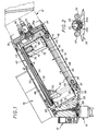
- la figure 1 est une vue en coupe longitudinale partielle, avec arrachement, de la partie terminale du dispositif de projection électrostatique, comprenant notamment un réservoir intermédiaire isolé et un projecteur de produit de revêtement connecté à ce réservoir;
- la figure 2 est une vue de détail à plus grande échelle, selon la coupe II-II de la figure 1; et
- la figure 3 est une vue partielle en coupe à plus grande échelle du dispositif de projection électrostatique, illustrant une variante du dispositif de mesure du déplacement du piston.
- Le dispositif de projection électrostatique tel que représenté comporte ici un robot multi-axes 11, connu en soi, dont on n'a représenté, en trait fantôme, que la partie terminale à laquelle est fixée en porte-à-faux, un sous-ensemble 12 comprenant un réservoir 13 muni intérieurement d'un piston 14, un projecteur électrostatique 15 de produit de revêtement, connecté pour être alimenté par le réservoir, un générateur de haute tension 16 et une unité de connexion 17 munie de raccords et de pneumovannes, pour le raccordement à une installation de nettoyage et d'alimentation en produit de revêtement choisi, cette installation n'étant pas représentée. La structure de l'unité de connexion ne fait pas partie de l'invention et ne sera donc pas décrite en détail. Il est simplement rappelé que le fluide de nettoyage et les produits de revêtement transitent par cette unité pendant les périodes de nettoyage et de remplissage du réservoir, lorsque le piston se trouve dans sa position extrême la plus proche du projecteur pour laquelle ledit réservoir 13 a un volume minimum. Le réservoir est défini dans une cavité 20 globalement cylindrique ménagée dans un corps 22 en matériau isolant, lequel est constitué de l'assemblage de deux blocs, un premier bloc 23 dans lequel est défini la plus grande partie du réservoir et qui est fixé à un socle 24 métallique porté par l'extrémité du robot 11 et un second bloc 25, portant notamment le projecteur électrostatique 15, son régulateur de débit 28 à actionnement pneumatique, et l'unité de connexion 17 précitée. Le piston 14 forme dans ladite cavité, une paroi mobile séparant une chambre de produit de revêtement 30 (en communication avec le projecteur électrostatique et l'unité de connexion) d'une chambre d'actionnement 32 remplie d'un fluide d'actionnement électriquement isolant, en l'occurrence de l'air. Un circuit d'alimentation en fluide d'actionnement 34 débouche nécessairement dans ladite chambre d'actionnement. Ce circuit s'étend entre ladite chambre d'actionnement et le socle 24 car, pour ne pas entraver les mouvements du robot et pour permettre un changement rapide du sous-ensemble 12, tous les circuits d'alimentation pneumatiques et les câbles électriques qui y sont raccordés, traversent ce socle de façon que les liaisons électriques et pneumatiques soient regroupées en une sorte de faisceau à l'intérieur du robot multi-axes. Ainsi, le sous-ensemble 12 vient s'appliquer sur le socle 24 et s'y trouve fixé grâce à une bague filetée 35. Ce montage réalise la continuité des différents circuits pneumatiques et les raccordements électriques basse tension, ici via un connecteur axial 36. Pour des raisons évidentes de sécurité, l'ensemble du robot, jusqu'à et y compris le socle 24, est au potentiel de la terre.
- Dans l'exemple spécifiquement décrit, le corps abrite également un autre composant blindé du point de vue électrique, c'est-à-dire comportant une enveloppe métallique destinée à être connectée au potentiel de la terre et donc susceptible de favoriser l'établissement de courants de rampage. Il s'agit d'un capteur résistif 40 formant une sorte de potentiomètre linéaire, de structure connue, susceptible d'être actionné au moyen d'un aimant 42 porté par le piston 14. Il comporte une enveloppe métallique 43, tubulaire électriquement connectée au socle. On rappelle brièvement qu'un tel capteur résistif comporte deux pistes rectilignes en matériau résistif 44a, 44b, agencées côte-à-côte tandis qu'un curseur 45 ou analogue constitué ou comportant un élément sensible à un champ magnétique est assujetti à se déplacer le long de ces deux pistes parallèlement au piston. Dans l'exemple, ledit curseur 45 est métallique et retenu en contact avec les deux pistes par la force de traction magnétique exercée par l'aimant 42.
- Bien entendu, ce capteur résistif 40 est destiné à permettre l'élaboration d'un signal électrique représentatif de la position du piston 14 à l'intérieur du réservoir. Il pourrait être remplacé par tout autre moyen de détection sans contact de la position du piston dans la cavité. Néanmoins, comme on le verra plus loin, l'invention permet de prendre en compte le problème supplémentaire créé par la présence d'un capteur blindé du point de vue électrique, c'est-à-dire dont l'enveloppe métallique est portée au potentiel de la terre.
- La paroi de fond 48 de la cavité qui n'est pas en contact avec le produit de revêtement et au moins la plus grande partie de la paroi cylindrique 49 de cette même cavité 20 sont définies dans le même bloc 23. Autrement dit, la surface de cette partie de cavité est continue, sans emboîtage ni assemblage et constitue une sorte de trou borgne à fond plat. En outre, un tronçon du circuit d'alimentation en air est agencé sensiblement parallèlement à cette cavité en direction opposée dudit socle 24 à partir de la paroi de fond 48. De cette façon, la distance entre la paroi de fond 48 et le socle métallique 24 peut être relativement faible de sorte que le sous-ensemble 12 monté en porte-à-faux à l'extrémité du bras de robot, soit aussi compact et léger que possible. En effet, un perçage direct entre le fond de la cavité et la partie 34a du circuit d'alimentation 34, ménagée dans le socle, imposerait d'augmenter considérablement la longueur du bloc 23 entre la cavité et ledit socle pour ménager une longueur de conduit suffisante, propre à éviter l'apparition de courants de rampage.
- Dans l'exemple spécifiquement décrit, le piston 14 est monté coulissant dans une chemise 50 tubulaire en matériau électriquement isolant, par exemple en céramique, verre, voire en matière plastique, montée ajustée dans la cavité 20 et le tronçon précité du circuit d'alimentation 34 en fluide d'actionnement est constitué par au moins un canal longitudinal 54 défini entre la surface de la cavité et la face externe de la chemise. Plus précisément, dans l'exemple, ladite chemise tubulaire 50 comporte au moins une gorge longitudinale 55 sur sa face extérieure, s'étendant depuis l'extrémité de ladite chemise jouxtant la paroi de fond de la cavité jusqu'à une gorge circulaire 56 de raccordement communiquant avec un perçage 57 dudit corps faisant partie dudit circuit d'alimentation en fluide d'actionnement. De préférence, comme représenté, la chemise tubulaire 50 comporte une pluralité de gorges longitudinales 55 régulièrement réparties sur sa face extérieure et communiquant toutes avec ladite gorge circulaire 56 de raccordement. La chemise est percée radialement ou crénelée à l'extrémité de chaque gorge longitudinale pour établir la communication entre lesdites gorges et la chambre d'actionnement 48. Le bord correspondant de la jupe du piston 14 est également crénelé, pour la même raison. En amont du perçage 57, le circuit d'alimentation en fluide d'actionnement comporte un tuyau rectiligne 58 installé longitudinalement dans un évidement cylindrique externe 59 pratiqué sur la quasi-totalité de la longueur du bloc 23 pour alléger le sous-ensemble 12 monté en porte-à-faux sur le robot. Ce tuyau est connecté, par des embouts de raccordement vissés, au perçage 57 d'une part et à la partie 34a du circuit ménagée dans le socle, d'autre part. Le circuit 34 est lui-même raccordé à une source d'alimentation en air comprimé, non représentée. D'une façon générale, les autres circuits d'air alimentant, par exemple, le pulvérisateur 15 et le régulateur 28 sont agencés de la même façon, c'est-à-dire qu'ils traversent le socle 24 et se prolongent par un tuyau installé dans l'évidement 59. Ce dernier est recouvert d'un manchon cylindrique de protection 60, en matériau isolant.
- Un joint d'étanchéité 62 est intercalé entre les deux blocs de matériau isolant 23, 25 constituant le corps 22, à l'extérieur de la chemise 50. Par conséquent, l'air d'actionnement injecté au niveau de la gorge circulaire 56 ne peut s'échapper par le plan d'assemblage des deux blocs.
- Ainsi, du point de vue électrique, même en considérant que la paroi de fond 48 de la cavité soit portée à la haute tension, notamment lorsque le piston 14 se trouve dans la position illustrée, on remarque que le circuit d'alimentation en air d'actionnement 34 comporte un tronçon de longueur suffisante (au moins entre ladite paroi de fond 48 et la gorge circulaire 56) pour qu'aucun courant de rampage ne puisse s'établir vers un quelconque élément métallique porté au potentiel de la terre. Dans l'exemple décrit, compte tenu des dimensions du réservoir, ce tronçon a une longueur de l'ordre de 20cm. Pour augmenter la sécurité, un anneau de garde tubulaire 65, en matériau isolant, est inséré dans les deux blocs 23, 25, perpendiculairement à leur surface d'assemblage et coaxialement à la cavité 20. Cet agencement est classique pour lutter contre les courants de rampage. Dans l'exemple, l'anneau de garde 65 est installé entre la cavité 20, à l'extérieur de la chemise 50, et le capteur résistif 40. Etant donné que ce dernier comporte une enveloppe métallique 43 mise au potentiel de la terre, ladite enveloppe est entourée d'une gaines en matériau isolant 68 sur au moins une partie de sa longueur, au moins au voisinage de l'extrémité dudit tronçon du circuit d'alimentation en air d'actionnement opposée à la paroi de fond 48 de la cavité, c'est-à-dire au voisinage de la gorge circulaire 56 et du plan de joint des deux blocs. Cette gaine s'étend ici sur une dizaine de centimètres et diminue encore le risque de voir s'établir un courant de rampage entre le circuit d'alimentation en air d'actionnement et ledit capteur résistif.
- Le bloc 25 fermant la cavité comporte aussi un alésage cylindrique prolongeant ladite cavité et dans lequel s'engage la chemise tubulaire 50. Cet alésage cylindrique se termine par un épaulement 69 dont la largeur correspond à l'épaisseur de la chemise. Cet épaulement est situé à très peu de distance de la paroi d'extrémité 70 de la cavité, définie dans le bloc 25, où débouchent les conduits reliés au projecteur 15 et à l'unité de connexion 17. Un joint 71 est intercalé entre l'extrémité de ladite chemise et l'épaulement, ce joint est dimensionné pour définir une surface sensiblement continue dans la chambre de produit de revêtement. Il est réalisé dans un matériau qui ne flue pas, de façon à éviter toute accumulation de produit de revêtement au voisinage de l'extrémité de la chemise, pendant toute la durée de vie du dispositif.
- La face 72 du piston 14 qui fait face à la paroi d'extrémité 70 est munie d'inserts 73 faisant saillie pour éviter l'adhérence des parois en bout de course.
- Comme mentionné précédemment, le piston 14 porte un aimant 42, lui-même en contact avec deux pièces polaires 74 qui coulissent le long de la surface intérieure de la chemise 20. Cet équipage magnétique permet d'entraîner le curseur 45 du capteur résistif. En outre, un aimant, ici le même aimant 42, est couplé magnétiquement (par les mêmes pièces polaires) à des moyens de guidage longitudinal, en matériau magnétique, par exemple en fer doux, permettant de stabiliser le piston en rotation. Dans l'exemple, ces moyens de guidage sont constitués par deux tiges 77 en fer doux, disposées de part et d'autre du capteur résistif sur au moins toute la longueur du trajet du piston. On évite ainsi de façon simple tout clavetage mécanique du piston, générateur de frottements et source de fuites. Le piston étant ainsi immobilisé en rotation, on est sûr de la qualité du couplage magnétique entre le curseur 45 et l'aimant 42 et on est donc toujours en mesure de connaître la position exacte du piston dans la cavité, ce qui permet de commander efficacement les variations souhaitées de débit.
- Selon une variante de l'invention, représentée figure 3, où des éléments de structure analogues à ceux de la figure 1 portent les mêmes références numériques que sur celle-ci, le capteur de déplacement du piston peut aussi être un détecteur optique. Une source lumineuse monochromatique 101, telle qu'une diode laser émet un faisceau lumineux A en direction d'une bille réfléchissante 102 fixée à l'arrière du piston 14. Le signal lumineux réfléchi B est capté par un interféromètre 103, par exemple un interféromètre de Michaelson, et transmis par un conducteur électrique 104 à une unité centrale de commande non représentée. Le signal obtenu est représentatif de la vitesse de déplacement du piston, donc du débit instantané de produit de revêtement. En particulier, il n'est pas nécessaire de dériver un signal de position pour connaître cette vitesse, donc ce débit. Une plaque transparente et isolante 105, par exemple en verre, enchâssée dans le fond du réservoir, isole l'intérieur du réservoir 13 de la source de lumière 101 et du détecteur 103. Il n'y a pas de contact physique entre le dispositif de mesure et l'intérieur du réservoir 13, tout rampage de la haute tension est ainsi évité. Ce système est particulièrement avantageux car il ne nécessite pas de calibrer ou d'étalonner le dispositif de mesure lorsque le réservoir 13 a été démonté. Sa précision est de l'ordre de 10 micromètres et indépendante des conditions de fonctionnement, telles que la qualité de l'air ambiant ou la propreté de la surface de la bille 102. De plus, il est possible de prévoir que le dispositif de mesure demeure en place lorsqu'on procède à l'échange standard du sous-ensemble 12.
- On pourrait aussi remplacer ces moyens de mesure par un détecteur à effet Hall.
Claims (11)
Applications Claiming Priority (2)
| Application Number | Priority Date | Filing Date | Title |
|---|---|---|---|
| FR9210746A FR2695327B1 (fr) | 1992-09-09 | 1992-09-09 | Dispositif de projection électrostatique de produit de revêtement électriquement conducteur, muni d'un réservoir isolé adapté à contenir un tel produit. |
| FR9210746 | 1992-09-09 |
Publications (2)
| Publication Number | Publication Date |
|---|---|
| EP0587467A1 true EP0587467A1 (fr) | 1994-03-16 |
| EP0587467B1 EP0587467B1 (fr) | 1997-02-26 |
Family
ID=9433335
Family Applications (1)
| Application Number | Title | Priority Date | Filing Date |
|---|---|---|---|
| EP93401996A Expired - Lifetime EP0587467B1 (fr) | 1992-09-09 | 1993-08-03 | Dispositif de projection électrostatique de produit de revêtement électriquement conducteur, muni d'un réservoir isolé adapté à contenir un tel produit |
Country Status (6)
| Country | Link |
|---|---|
| US (1) | US5310120A (fr) |
| EP (1) | EP0587467B1 (fr) |
| JP (1) | JP2796236B2 (fr) |
| DE (1) | DE69308253T2 (fr) |
| ES (1) | ES2098005T3 (fr) |
| FR (1) | FR2695327B1 (fr) |
Cited By (4)
| Publication number | Priority date | Publication date | Assignee | Title |
|---|---|---|---|---|
| US6422491B1 (en) | 1997-12-18 | 2002-07-23 | Lactec Gmbh Gesellschaft Fuer Moderne Lackiertechnik | Method and device for isolating an electro-conductive flowing medium |
| EP1736244A1 (fr) * | 2005-06-23 | 2006-12-27 | SAMES Technologies | Appareil de démontage d'un piston, son utilisation et installation de projection de produit de revêtement comportant un tel appareil |
| CN100537045C (zh) * | 2005-06-23 | 2009-09-09 | 萨姆斯技术公司 | 包括贮存器的喷射涂层产品的装置和设备 |
| FR2939333A1 (fr) * | 2008-12-09 | 2010-06-11 | Sames Technologies | Projecteur de produit de revetement et procede pour reapprovisionner un tel projecteur |
Families Citing this family (22)
| Publication number | Priority date | Publication date | Assignee | Title |
|---|---|---|---|---|
| DE4312262A1 (de) * | 1993-04-15 | 1994-10-20 | Gema Volstatic Ag | Elektrostatische Sprühvorrichtung |
| US5341990A (en) * | 1993-06-11 | 1994-08-30 | Nordson Corporation | Apparatus and method for dispensing electrically conductive coating material including a pneumatic/mechanical control |
| JP2801541B2 (ja) * | 1993-11-24 | 1998-09-21 | 旭サナック株式会社 | 電圧ブロック装置 |
| FR2722432B1 (fr) * | 1994-07-13 | 1996-10-25 | Sames Sa | Dispositif de projection comprenant un reservoir de produit de revetement et procede de nettoyage et de remplissage d'un tel reservoir |
| FR2727039B3 (fr) * | 1994-11-18 | 1996-12-13 | Sames Sa | Procede et dispositif de projection de produit de revetement |
| US5549755A (en) * | 1994-12-08 | 1996-08-27 | Nordson Corporation | Apparatus for supplying conductive coating materials including transfer units having a combined shuttle and pumping device |
| DE19610588B4 (de) * | 1996-03-18 | 2010-08-05 | Dürr Systems GmbH | Beschichtungsmaschine mit auswechselbarem Behälter |
| DE19610589A1 (de) * | 1996-03-18 | 1997-09-25 | Duerr Gmbh & Co | Verfahren und System zur Farbversorgung einer Beschichtungsanlage |
| WO1999036182A1 (fr) * | 1998-01-13 | 1999-07-22 | Abb K.K. | Dispositif de revetement de type tete de pulverisation rotative |
| JP3263373B2 (ja) * | 1998-12-18 | 2002-03-04 | エービービー株式会社 | 自動塗装装置 |
| KR100852155B1 (ko) * | 2001-07-02 | 2008-08-13 | 버텍 비젼 인터내셔널 인코포레이티드 | 경질의 비금속 기판 내의 오프닝 어블레이팅 방법 |
| DE10136720A1 (de) | 2001-07-27 | 2003-02-13 | Duerr Systems Gmbh | Dosiersystem für eine Beschichtungsvorrichtung |
| US6676049B2 (en) | 2001-11-16 | 2004-01-13 | Efc Systems, Inc. | Bell cup powder spray applicator |
| AU2002365392A1 (en) * | 2001-11-21 | 2003-06-10 | Fanuc Robotics North America, Inc. | Apparatus and method for filling a painting robot canister |
| DE10211244A1 (de) | 2002-03-13 | 2003-10-23 | Lactec Ges Fuer Moderne Lackte | Lackieranlage zum Aufbringen von flüssigem Beschichtungsmaterial |
| US7056387B2 (en) * | 2003-12-10 | 2006-06-06 | Efc Systems, Inc. | Apparatus and method for electrostatic spraying of conductive coating materials |
| FR2890876B1 (fr) * | 2005-09-19 | 2007-11-30 | Sames Technologies Soc Par Act | Installation de projection de produit de revetement multi-composant |
| DE202006021283U1 (de) | 2005-10-07 | 2014-08-27 | Dürr Systems GmbH | Beschichtungsmittel-Versorgungseinrichtung |
| CN101277768B (zh) * | 2005-10-07 | 2011-03-23 | Abb股份有限公司 | 涂料供给设备及系统 |
| US9713816B2 (en) * | 2015-03-19 | 2017-07-25 | Paccar Inc | Zero waste color change system |
| US10239072B2 (en) * | 2015-09-22 | 2019-03-26 | Honda Motor Co. Ltd. | Energy dissipation unit for high voltage charged paint system |
| CN112160561A (zh) * | 2020-11-01 | 2021-01-01 | 湖南欧龙艺墅建筑材料有限公司 | 一种建筑装饰装修喷涂装置 |
Citations (2)
| Publication number | Priority date | Publication date | Assignee | Title |
|---|---|---|---|---|
| FR2635990A1 (fr) * | 1988-09-07 | 1990-03-09 | Sames Sa | Installation de projection de produit de revetement a debit controle |
| FR2668956A1 (fr) * | 1990-11-08 | 1992-05-15 | Honda Motor Co Ltd | Appareil de peinture par pulverisation electrostatique. |
Family Cites Families (10)
| Publication number | Priority date | Publication date | Assignee | Title |
|---|---|---|---|---|
| DE3440381A1 (de) * | 1984-11-05 | 1986-05-07 | Ransburg Gmbh, 6056 Heusenstamm | Verfahren und vorrichtung zum automatischen elektrostatischen spruehbeschichten |
| SE449451B (sv) * | 1986-03-24 | 1987-05-04 | Leif Tilly | Sett och anordning att tillfora ett elektriskt ledande, flytande medium fran ett forradssystem till en forbrukningsstation |
| JPH053233Y2 (fr) * | 1986-09-10 | 1993-01-26 | ||
| FR2609252B1 (fr) * | 1987-01-02 | 1989-04-21 | Sames Sa | Installation de projection de produit de revetement tel que par exemple une peinture et notamment installation de projection electrostatique de peinture a base d'eau |
| DE3725172A1 (de) * | 1987-05-27 | 1989-02-09 | Behr Industrieanlagen | Verfahren und anlage zum elektrostatischen beschichten mit leitfaehigem material |
| US4798341A (en) * | 1987-09-28 | 1989-01-17 | The Devilbiss Company | Spray gun for robot mounting |
| FR2656460B1 (fr) * | 1989-12-22 | 1994-02-11 | Sames Sa | Dispositif d'isolation electrique formant element de conduit et installation comportant un tel dispositif. |
| GB2249976B (en) * | 1990-11-08 | 1994-08-03 | Honda Motor Co Ltd | Method of and apparatus for electrostatically spray-coating a workpiece with paint |
| FR2669245B1 (fr) * | 1990-11-20 | 1993-02-19 | Sames Sa | Installation de projection electrostatique de produit de revetement liquide conducteur. |
| GB2252262B (en) * | 1991-01-22 | 1994-08-31 | Honda Motor Co Ltd | Structure for preventing current from leaking out of devices for electrostatic spray coating |
-
1992
- 1992-09-09 FR FR9210746A patent/FR2695327B1/fr not_active Expired - Fee Related
-
1993
- 1993-08-03 ES ES93401996T patent/ES2098005T3/es not_active Expired - Lifetime
- 1993-08-03 DE DE69308253T patent/DE69308253T2/de not_active Expired - Fee Related
- 1993-08-03 US US08/101,019 patent/US5310120A/en not_active Expired - Lifetime
- 1993-08-03 EP EP93401996A patent/EP0587467B1/fr not_active Expired - Lifetime
- 1993-09-09 JP JP5224608A patent/JP2796236B2/ja not_active Expired - Fee Related
Patent Citations (2)
| Publication number | Priority date | Publication date | Assignee | Title |
|---|---|---|---|---|
| FR2635990A1 (fr) * | 1988-09-07 | 1990-03-09 | Sames Sa | Installation de projection de produit de revetement a debit controle |
| FR2668956A1 (fr) * | 1990-11-08 | 1992-05-15 | Honda Motor Co Ltd | Appareil de peinture par pulverisation electrostatique. |
Cited By (8)
| Publication number | Priority date | Publication date | Assignee | Title |
|---|---|---|---|---|
| US6422491B1 (en) | 1997-12-18 | 2002-07-23 | Lactec Gmbh Gesellschaft Fuer Moderne Lackiertechnik | Method and device for isolating an electro-conductive flowing medium |
| EP1736244A1 (fr) * | 2005-06-23 | 2006-12-27 | SAMES Technologies | Appareil de démontage d'un piston, son utilisation et installation de projection de produit de revêtement comportant un tel appareil |
| FR2887473A1 (fr) * | 2005-06-23 | 2006-12-29 | Sames Technologies Soc Par Act | Appareil de demontage d'un piston, son utilisation et installation de projection de produit de revetement comportant un tel appareil |
| CN100537045C (zh) * | 2005-06-23 | 2009-09-09 | 萨姆斯技术公司 | 包括贮存器的喷射涂层产品的装置和设备 |
| US7931215B2 (en) | 2005-06-23 | 2011-04-26 | Sames Technologies | Device and an installation for spraying a coating fluid, and including a reservoir |
| FR2939333A1 (fr) * | 2008-12-09 | 2010-06-11 | Sames Technologies | Projecteur de produit de revetement et procede pour reapprovisionner un tel projecteur |
| WO2010067014A1 (fr) * | 2008-12-09 | 2010-06-17 | Sames Technologies | Projecteur de produit de revetement et procede pour reapprovisionner un tel projecteur en produit de revetement |
| US8746167B2 (en) | 2008-12-09 | 2014-06-10 | Sames Technologies | Coating product spraygun and method for resupplying coating product to such a spraygun |
Also Published As
| Publication number | Publication date |
|---|---|
| US5310120A (en) | 1994-05-10 |
| ES2098005T3 (es) | 1997-04-16 |
| DE69308253D1 (de) | 1997-04-03 |
| JPH06154664A (ja) | 1994-06-03 |
| FR2695327A1 (fr) | 1994-03-11 |
| EP0587467B1 (fr) | 1997-02-26 |
| JP2796236B2 (ja) | 1998-09-10 |
| DE69308253T2 (de) | 1997-10-09 |
| FR2695327B1 (fr) | 1995-07-07 |
Similar Documents
| Publication | Publication Date | Title |
|---|---|---|
| EP0587467B1 (fr) | Dispositif de projection électrostatique de produit de revêtement électriquement conducteur, muni d'un réservoir isolé adapté à contenir un tel produit | |
| FR2977389A1 (fr) | Prise electrique munie de moyens d'identification, fiche electrique et ensemble electrique associes. | |
| WO1993023720A1 (fr) | Capteur de position a aimant permanent et sonde magnetosensible | |
| EP0926501A1 (fr) | Montage de roue de patin en ligne avec dispositif de détection de la vitesse de rotation | |
| EP0652438A1 (fr) | Joint d'étanchéité pour roulements à capteur d'informations et roulement ainsi équipé | |
| FR3082224A1 (fr) | Debitmetre a mini-turbine et outil de fond de puits comprenant un reseau de debitmetre a mini-turbine pour fonctionner dans un puits d'hydrocarbures. | |
| EP2393604B1 (fr) | Projecteur électrostatique comportant un dispositif de détection de vitesse de rotation | |
| FR2877083A1 (fr) | Capteur optique de proximite pour instrument de projection de liquide et instrument de projection de liquide equipe d'un tel capteur | |
| FR2558252A1 (fr) | Dispositif perfectionne pour la mesure de niveau ou volume de liquide dans un reservoir, comportant un flotteur | |
| FR2676026A1 (fr) | Element d'alimentation en carburant pour un vehicule. | |
| CA2409534C (fr) | Hydrophone a inhibition automatique en cas de depassement d'un seuil d'immersion ajustable | |
| FR2535785A1 (fr) | Dispositif pour piston de poussee, destine a etre en particulier utilise en tant que verin de ripage dans des installations d'abattage minieres, comprenant un systeme a aimants permanents dispose sur la tige du piston | |
| FR2517437A1 (fr) | Connecteur de fibres optiques | |
| FR2794236A1 (fr) | Dispositif permettant de connaitre la position et de mesurer les deplacements du piston ou de la tige de piston dans la chambre d'un verin du type comprenant un capteur potentiometrique rectiligne lineaire | |
| CA2473161C (fr) | Ensemble a roue equipe d'un tachymetre | |
| FR2568327A1 (fr) | Dispositif de fixation sur une paroi du conduit de gainage d'une commande a cable | |
| FR2776135A1 (fr) | Conduit associe a un conducteur electrique de detection, par exemple pour le tirage ou poussage d'un cable | |
| EP0419309B1 (fr) | Dispositif d'échantillonage dans un puits | |
| EP0959362B1 (fr) | Dispositif de mesure d'une grandeur physique liée à la rotation d'un organe | |
| EP0239443B1 (fr) | Capteur d'éclairement perfectionné | |
| EP0353117A1 (fr) | Dispositif de détection de la position d'un organe mobile à l'intérieur d'un organe fixe | |
| WO2004046640A1 (fr) | Dispositif pour mesurer sensiblement en continu les variations du diamètre de la paroi intérieure d'un conduit | |
| FR2597595A3 (fr) | Dispositif pour detecter le niveau d'un liquide dans un reservoir | |
| FR2759777A1 (fr) | Dispositif pour mesurer la rotation d'un element rotatif | |
| EP0958984B1 (fr) | Bougie de véhicule ferroviaire |
Legal Events
| Date | Code | Title | Description |
|---|---|---|---|
| PUAI | Public reference made under article 153(3) epc to a published international application that has entered the european phase |
Free format text: ORIGINAL CODE: 0009012 |
|
| AK | Designated contracting states |
Kind code of ref document: A1 Designated state(s): BE DE ES FR GB IT SE |
|
| 17P | Request for examination filed |
Effective date: 19940414 |
|
| 17Q | First examination report despatched |
Effective date: 19950724 |
|
| GRAG | Despatch of communication of intention to grant |
Free format text: ORIGINAL CODE: EPIDOS AGRA |
|
| GRAH | Despatch of communication of intention to grant a patent |
Free format text: ORIGINAL CODE: EPIDOS IGRA |
|
| GRAH | Despatch of communication of intention to grant a patent |
Free format text: ORIGINAL CODE: EPIDOS IGRA |
|
| GRAA | (expected) grant |
Free format text: ORIGINAL CODE: 0009210 |
|
| AK | Designated contracting states |
Kind code of ref document: B1 Designated state(s): BE DE ES FR GB IT SE |
|
| REF | Corresponds to: |
Ref document number: 69308253 Country of ref document: DE Date of ref document: 19970403 |
|
| REG | Reference to a national code |
Ref country code: ES Ref legal event code: FG2A Ref document number: 2098005 Country of ref document: ES Kind code of ref document: T3 |
|
| ITF | It: translation for a ep patent filed |
Owner name: ING. ZINI MARANESI & C. S.R.L. |
|
| GBT | Gb: translation of ep patent filed (gb section 77(6)(a)/1977) |
Effective date: 19970709 |
|
| PLBE | No opposition filed within time limit |
Free format text: ORIGINAL CODE: 0009261 |
|
| STAA | Information on the status of an ep patent application or granted ep patent |
Free format text: STATUS: NO OPPOSITION FILED WITHIN TIME LIMIT |
|
| 26N | No opposition filed | ||
| REG | Reference to a national code |
Ref country code: GB Ref legal event code: IF02 |
|
| REG | Reference to a national code |
Ref country code: FR Ref legal event code: TP |
|
| REG | Reference to a national code |
Ref country code: ES Ref legal event code: PC2A |
|
| BECH | Be: change of holder |
Owner name: *SAMES TECHNOLOGIES SAS Effective date: 20030620 |
|
| BECN | Be: change of holder's name |
Owner name: *SAMES TECHNOLOGIES SAS Effective date: 20030620 |
|
| REG | Reference to a national code |
Ref country code: GB Ref legal event code: 732E |
|
| PGFP | Annual fee paid to national office [announced via postgrant information from national office to epo] |
Ref country code: SE Payment date: 20040715 Year of fee payment: 12 |
|
| PGFP | Annual fee paid to national office [announced via postgrant information from national office to epo] |
Ref country code: GB Payment date: 20040727 Year of fee payment: 12 |
|
| PGFP | Annual fee paid to national office [announced via postgrant information from national office to epo] |
Ref country code: DE Payment date: 20040806 Year of fee payment: 12 |
|
| PGFP | Annual fee paid to national office [announced via postgrant information from national office to epo] |
Ref country code: ES Payment date: 20040816 Year of fee payment: 12 |
|
| PGFP | Annual fee paid to national office [announced via postgrant information from national office to epo] |
Ref country code: BE Payment date: 20040901 Year of fee payment: 12 |
|
| PG25 | Lapsed in a contracting state [announced via postgrant information from national office to epo] |
Ref country code: IT Free format text: LAPSE BECAUSE OF NON-PAYMENT OF DUE FEES;WARNING: LAPSES OF ITALIAN PATENTS WITH EFFECTIVE DATE BEFORE 2007 MAY HAVE OCCURRED AT ANY TIME BEFORE 2007. THE CORRECT EFFECTIVE DATE MAY BE DIFFERENT FROM THE ONE RECORDED. Effective date: 20050803 Ref country code: GB Free format text: LAPSE BECAUSE OF NON-PAYMENT OF DUE FEES Effective date: 20050803 |
|
| PG25 | Lapsed in a contracting state [announced via postgrant information from national office to epo] |
Ref country code: SE Free format text: LAPSE BECAUSE OF NON-PAYMENT OF DUE FEES Effective date: 20050804 Ref country code: ES Free format text: LAPSE BECAUSE OF NON-PAYMENT OF DUE FEES Effective date: 20050804 |
|
| PG25 | Lapsed in a contracting state [announced via postgrant information from national office to epo] |
Ref country code: BE Free format text: LAPSE BECAUSE OF NON-PAYMENT OF DUE FEES Effective date: 20050831 |
|
| PG25 | Lapsed in a contracting state [announced via postgrant information from national office to epo] |
Ref country code: DE Free format text: LAPSE BECAUSE OF NON-PAYMENT OF DUE FEES Effective date: 20060301 |
|
| EUG | Se: european patent has lapsed | ||
| GBPC | Gb: european patent ceased through non-payment of renewal fee |
Effective date: 20050803 |
|
| REG | Reference to a national code |
Ref country code: ES Ref legal event code: FD2A Effective date: 20050804 |
|
| BERE | Be: lapsed |
Owner name: *SAMES TECHNOLOGIES SAS Effective date: 20050831 |
|
| PGFP | Annual fee paid to national office [announced via postgrant information from national office to epo] |
Ref country code: FR Payment date: 20080812 Year of fee payment: 16 |
|
| REG | Reference to a national code |
Ref country code: FR Ref legal event code: ST Effective date: 20100430 |
|
| PG25 | Lapsed in a contracting state [announced via postgrant information from national office to epo] |
Ref country code: FR Free format text: LAPSE BECAUSE OF NON-PAYMENT OF DUE FEES Effective date: 20090831 |