EP0589328B1 - Syringe pump with graphical display of error conditions - Google Patents
Syringe pump with graphical display of error conditions Download PDFInfo
- Publication number
- EP0589328B1 EP0589328B1 EP93114709A EP93114709A EP0589328B1 EP 0589328 B1 EP0589328 B1 EP 0589328B1 EP 93114709 A EP93114709 A EP 93114709A EP 93114709 A EP93114709 A EP 93114709A EP 0589328 B1 EP0589328 B1 EP 0589328B1
- Authority
- EP
- European Patent Office
- Prior art keywords
- plunger
- syringe
- indicium
- syringe pump
- barrel
- Prior art date
- Legal status (The legal status is an assumption and is not a legal conclusion. Google has not performed a legal analysis and makes no representation as to the accuracy of the status listed.)
- Expired - Lifetime
Links
Images


Classifications
-
- A—HUMAN NECESSITIES
- A61—MEDICAL OR VETERINARY SCIENCE; HYGIENE
- A61M—DEVICES FOR INTRODUCING MEDIA INTO, OR ONTO, THE BODY; DEVICES FOR TRANSDUCING BODY MEDIA OR FOR TAKING MEDIA FROM THE BODY; DEVICES FOR PRODUCING OR ENDING SLEEP OR STUPOR
- A61M5/00—Devices for bringing media into the body in a subcutaneous, intra-vascular or intramuscular way; Accessories therefor, e.g. filling or cleaning devices, arm-rests
- A61M5/14—Infusion devices, e.g. infusing by gravity; Blood infusion; Accessories therefor
- A61M5/142—Pressure infusion, e.g. using pumps
- A61M5/145—Pressure infusion, e.g. using pumps using pressurised reservoirs, e.g. pressurised by means of pistons
- A61M5/1452—Pressure infusion, e.g. using pumps using pressurised reservoirs, e.g. pressurised by means of pistons pressurised by means of pistons
- A61M5/1456—Pressure infusion, e.g. using pumps using pressurised reservoirs, e.g. pressurised by means of pistons pressurised by means of pistons with a replaceable reservoir comprising a piston rod to be moved into the reservoir, e.g. the piston rod is part of the removable reservoir
-
- A—HUMAN NECESSITIES
- A61—MEDICAL OR VETERINARY SCIENCE; HYGIENE
- A61M—DEVICES FOR INTRODUCING MEDIA INTO, OR ONTO, THE BODY; DEVICES FOR TRANSDUCING BODY MEDIA OR FOR TAKING MEDIA FROM THE BODY; DEVICES FOR PRODUCING OR ENDING SLEEP OR STUPOR
- A61M5/00—Devices for bringing media into the body in a subcutaneous, intra-vascular or intramuscular way; Accessories therefor, e.g. filling or cleaning devices, arm-rests
- A61M5/14—Infusion devices, e.g. infusing by gravity; Blood infusion; Accessories therefor
- A61M5/142—Pressure infusion, e.g. using pumps
- A61M5/145—Pressure infusion, e.g. using pumps using pressurised reservoirs, e.g. pressurised by means of pistons
- A61M5/1452—Pressure infusion, e.g. using pumps using pressurised reservoirs, e.g. pressurised by means of pistons pressurised by means of pistons
- A61M2005/14573—Pressure infusion, e.g. using pumps using pressurised reservoirs, e.g. pressurised by means of pistons pressurised by means of pistons with a replaceable reservoir for quick connection/disconnection with a driving system
-
- A—HUMAN NECESSITIES
- A61—MEDICAL OR VETERINARY SCIENCE; HYGIENE
- A61M—DEVICES FOR INTRODUCING MEDIA INTO, OR ONTO, THE BODY; DEVICES FOR TRANSDUCING BODY MEDIA OR FOR TAKING MEDIA FROM THE BODY; DEVICES FOR PRODUCING OR ENDING SLEEP OR STUPOR
- A61M2205/00—General characteristics of the apparatus
- A61M2205/14—Detection of the presence or absence of a tube, a connector or a container in an apparatus
-
- A—HUMAN NECESSITIES
- A61—MEDICAL OR VETERINARY SCIENCE; HYGIENE
- A61M—DEVICES FOR INTRODUCING MEDIA INTO, OR ONTO, THE BODY; DEVICES FOR TRANSDUCING BODY MEDIA OR FOR TAKING MEDIA FROM THE BODY; DEVICES FOR PRODUCING OR ENDING SLEEP OR STUPOR
- A61M39/00—Tubes, tube connectors, tube couplings, valves, access sites or the like, specially adapted for medical use
- A61M39/22—Valves or arrangement of valves
- A61M39/28—Clamping means for squeezing flexible tubes, e.g. roller clamps
- A61M39/281—Automatic tube cut-off devices, e.g. squeezing tube on detection of air
-
- A—HUMAN NECESSITIES
- A61—MEDICAL OR VETERINARY SCIENCE; HYGIENE
- A61M—DEVICES FOR INTRODUCING MEDIA INTO, OR ONTO, THE BODY; DEVICES FOR TRANSDUCING BODY MEDIA OR FOR TAKING MEDIA FROM THE BODY; DEVICES FOR PRODUCING OR ENDING SLEEP OR STUPOR
- A61M5/00—Devices for bringing media into the body in a subcutaneous, intra-vascular or intramuscular way; Accessories therefor, e.g. filling or cleaning devices, arm-rests
- A61M5/14—Infusion devices, e.g. infusing by gravity; Blood infusion; Accessories therefor
- A61M5/142—Pressure infusion, e.g. using pumps
- A61M5/145—Pressure infusion, e.g. using pumps using pressurised reservoirs, e.g. pressurised by means of pistons
- A61M5/1452—Pressure infusion, e.g. using pumps using pressurised reservoirs, e.g. pressurised by means of pistons pressurised by means of pistons
- A61M5/1458—Means for capture of the plunger flange
Definitions
- This invention relates to the field of syringe pumps.
- it relates to displays for indicating operating conditions in syringe pumps.
- a syringe pump is a device for pumping fluid from a syringe into a patient. It typically comprises a housing to which a syringe is secured and a mechanism for pushing the plunger of the syringe to expel the fluid from the syringe, thus infusing the fluid into the patient.
- certain conditions may arise at various parts of the pump.
- the user is informed of error conditions in the syringe pump by means of indicia on a display.
- EP-A-0 314 880 describes a syringe pump according to the preamble of claim 1.
- the object of the present invention is to provide a syringe pump which allows a user to identify in a simple and easy way the location of error conditions.
- the syringe pump includes the following components: the syringe pump is housed in a housing which contains the drive mechanism for pushing the plunger of the syringe.
- the syringe is secured to the housing by means of a syringe clamp.
- the clamp is provided with a detector which detects the position of the clamp. The detector produces an electrical signal if the clamp is not properly positioned.
- the pump also may have a mechanism for holding the plunger in place, so that it cannot move independently of the pusher, thus preventing fluid from being siphoned from the syringe.
- This anti-siphon device is also provided with an electronic sensor which produces an electrical signal if the anti-siphon device is not properly positioned.
- the pusher may be driven by means of a motor driven lead screw and a half nut which engages the lead screw.
- the half nut can be disengaged from the lead screw.
- a transducer is provided to detect whether or not the half nut is engaged with the lead screw.
- the pump also has a mechanism for detecting the position of the syringe plunger relative to the barrel. An indicium is activated when the plunger has fully entered the barrel.
- the syringe pump has a display for alerting the user to error conditions arising at all or some of the points described above.
- the display is in the form of a graphical representation of a syringe.
- the graphical representation of the syringe has indicia located at the points on the graphical representation which generally correspond to the points on the actual syringe at which the error conditions described above may occur.
- the display has indicia at all or some the following points: The point on the syringe barrel at which the clamp holds the barrel in place; the point on the plunger at which the antisiphon device engages the plunger; and the point on the plunger at which the plunger makes contact with the syringe pusher.
- the display also has an indicium at a position on the graphical representation corresponding to the point at which the stopper of the syringe plunger resides when the syringe plunger has fully entered the syringe barrel.
- the indicium will be activated.
- the user is provided with a simple, easy to read means for identifying the location of error conditions and the end of the infusion cycle in the syringe pump.
- a syringe pump 8 embodying the invention is shown in Fig. 1.
- Housing 10 supports syringe barrel 12, pusher 14 and syringe clamp 16.
- Syringe clamp 16 holds syringe barrel 12 in place on housing 10.
- Plunger 18 is pushed by pusher 14 which is driven by an electric motor via a lead screw (see Fig. 2).
- Pusher 14 is provided with antisiphon catch 20 which engages flange 18a of plunger 18, thus preventing plunger 18 from moving independently of pusher 14.
- Pusher 14 is also provided with pressure plate 22 for pushing directly against flange 18a thereby pumping fluid from syringe barrel 12.
- Fig. 2 shows the chassis and mechanical components of pump 8.
- Chassis 226 carries motor 230 and lead screw 222.
- Motor 230 drives lead screw 222 via gear assembly 231.
- Pusher 14 is driven by the interaction of pusher block 228 with lead screw 222.
- Pusher block contains half nuts 322, 324 which interact with lead screw 222 (see Fig. 3).
- Pusher block 228 carries rack 234 such that rack 234 moves in unison with pusher block 228.
- Rack 234 is linked via pinion 233 to rotary potentiometer 232.
- rotary potentiometer 232 indicates the position of plunger 18.
- Rotary potentiometer 232 is a five turn rotary potentiometer of 1Kohm impedance, 0.25W power rating and a linearity better than 0.25% of full scale.
- Display panel 24 contains controls for adjusting various parameters of the pump.
- Display panel 24 also contains graphic 26 which is a graphical representation of syringe barrel 12 and plunger 18.
- Graphic 26 is made up of an outline 25 of the syringe, showing the barrel and the plunger.
- Graphic 26 also includes first, second and third indicia 30, 32 and 34.
- Also provided are an end of infusion indicator (fourth indicium 28), flow direction arrows 29a, 29c and 29d and an occlusion indicator 29b.
- First indicium 30 is located at a point on graphic 26 corresponding to the point on syringe barrel 12 at which clamp 16 holds syringe barrel 12 in place.
- Second indicium 32 is located at a point on graphic 26 which corresponds to the point on plunger 18 at which antisiphon catch 20 makes contact with plunger 18.
- Third indicium 34 is located at a point on the graphic which corresponds to the point at which pusher 14 pushes flange 18a of plunger 18, i.e. pressure plate 22.
- Second and third indicia 30, 32 and 34 are linked via electronics which will be described herein to transducers respectively connected to syringe clamp 16, antisiphon catch 20 and half nut 322.
- the corresponding indicium will indicate the error condition on graphic 26.
- End of infusion indicator (fourth indicium 28) is linked to rotary potentiometer 232.
- fourth indicium 28 When plunger 18 has fully entered syringe barrel 12, fourth indicium 28 will be activated to indicate the end of the infusion cycle.
- End of infusion indicator 28 is at a position on graphic 26 corresponding to the position of syringe plunger 18 when the end of the infusion is reached.
- Direction arrows 29a, 29c and 29d represent the flow of the infusate from syringe barrel 12.
- Occlusion indicator 29b points in the direction of the force resulting from the occurrence of an occlusion in the delivery line.
- Fig. 7 is a block diagram showing the main electronic components of the invention.
- Five transducers are provided to detect the parameters of the syringe pump which are displayed.
- the transducers are: position sensor 35, force transducer 36, antisiphon catch detector 38, disengage detector 40 and syringe clamp detector 42.
- the outputs of these transducers 62, 64 and 66 respectively are fed into central processing unit 45 via various signal processing or latching modules which will be described in detail herein.
- Central processing unit 45 comprises microprocessor 46 (Fig. 8a) with random access memory 53 (Fig. 8c), watchdog 48 (Fig. 8b), EPROM 50 (Fig. 8a) and EEPROM 52 (Fig. 8c).
- Watchdog 48 monitors microprocessor 46 to ensure its proper operation.
- EEPROM 52 contains data concerning the parameters of each of the various types of syringes which may be used in the pump, such as brand, size and model of syringe, volume of syringe, number of motor steps per ml infused, "hard-height" (i.e. the distance from the plunger flange to the open end of syringe barrel when the plunger has fully entered the barrel, the syringe frictional force in gF (i.e. Ff) and the syringe pressure under a 5kg load in millibars (i.e. Pc).
- EPROM 50 contains a software program which controls the operation of the syringe pump.
- the output of force transducer 36 is conditioned by signal conditioning circuit 54 (Fig. 8d), which converts the output of force transducer 36 into a form suitable for input into analog to digital converter 56 (Fig. 8e).
- Output 61 of position sensor 35 is conditioned by signal conditioning circuit 55 and is then also fed into analog to digital converter 56.
- Analog to digital converter 56 digitizes the analog outputs 60 and 61 and produces serial output 58 which is in turn fed into input port of microprocessor 46.
- EEPROM 52 contains data representing the outputs of position sensor (i.e. "hard-height" of the syringe) corresponding to the points at which plunger 18 has fully entered syringe barrel 12 for various types of syringe.
- antisiphon catch detector 38 When antisiphon catch 20 is disengaged, antisiphon catch detector 38 produces digital output 62 (See Fig. 8i). Similarly the opening of disengage mechanism 44 causes disengage detector 40 to produce an output 64 (Fig. 8f) and the opening of syringe clamp 16 causes syringe clamp detector (Fig. 8h) to produce an output 66. Each output 62, 64, 66 is fed into central processing unit 45 via latch 68 (Fig. 8f).
- Microprocessor 46 causes error conditions at clamp 16, disengage mechanism and antisiphon catch 20 to be displayed on display panel 24 (Fig. 8g).
- Display panel 24 comprises graphical representation 26 which in turn comprises syringe outline 25, first indicium 30 indicating an error condition at syringe clamp 16, second indicium 32 which indicates an error condition at antisiphon catch 20 and third indicium 34 which indicates that disengage 44 mechanism is disengaged.
- indicia 30, 32 and 34 correspond to light emitting diodes LD2, LD3 and LD16 respectively.
- Indicia 30, 32 and 34 are activated under the control of microprocessor 46 when error conditions arise.
- Indicia 30, 32 and 34 are driven through row and column latches 255 (IC1 and IC6 in Fig. 8m) which in turn activate appropriate driver transistors (Fig. 8g).
- LD2, LD3 and LD16 are part of a matrix of light emitting diodes which are lit up when the row and column of the matrix corresponding to the position of the particularly light emitting diode are activated.
- the remaining light emitting diodes in the matrix (not shown) are not used in the invention. For simplicity, the full matrix is not shown.
- the other diodes in the matrix which are not shown light up other indicia on the panel of syringe pump which are not material to the invention.
- Figs. 5 shows force transducer 36 in greater detail.
- Force transducer 36 is made up of four strain gauges in a wheatstone bridge configuration.
- the bridge has an impedance of 350 ohms or 1 Kohm with a tolerance of +/- 15%.
- the range of force measurements is 0 to 150 N.
- the bridge sensitivity is 1.7 mV/V to 2.4 mV/V under a load of 150 N at 20 degrees centigrade.
- the bridge is powered intermittently under the control of microprocessor 46 (line CDANA in Figs. 8a and 8d) in order to conserve energy.
- Strain gauges 112 are glued onto beam 114. When force is applied to pressure plate 22, beam 114 flexes, causing strain gauges 112 to distort and produce output 60.
- Output 60 of force transducer 36 is fed into conditioning module 54 (Fig. 8d) and thereafter into analog to digital converter 56 which converts the conditioned output into serial output 58.
- Serial output 58 is then fed into input of microprocessor 46.
- the output 61 of position sensor 35 is similarly conditioned by signal conditioning circuit 55 and fed into analog to digital converter 56.
- EPROM 50 Resident in EPROM 50 is a software program for microprocessor 46 which calculates the pressure inside syringe 12 continuously as the force on the plunger 18 is measured by force transducer 36. Certain parameters which are used by the program to calculate the pressure in the syringe and stored in EEPROM 52. Since syringe pump 8 is programmable to accommodate various types of syringe, a set of parameters for each type of syringe, is stored in EEPROM 52.
- the parameters stored in EEPROM 52 include:
- microprocessor 46 uses the program in EPROM 50 to calculate the pressure in the syringe. Microprocessor 46 then compares the calculated pressure with the pressure threshold selected by the user. If the calculated pressure exceeds the threshold, an occlusion alarm is generated by microprocessor 46.
- microprocessor 46 actuates indicium 280 (LD14 in Fig. 8j, driven by transistors Q14 and Q2 in Fig. 8h).
- Clamp 16 comprises a spring loaded shaft which enables clamp 16 to be lifted and turned so that the syringe can be placed and removed.
- Clamp 16 is provided with a syringe clamp detector 42 (Fig. 8h) which detects whether or not clamp 16 is properly placed. When clamp 16 is properly placed, output 66 is low.
- Detector 42 comprises optical detector 42a, and associated circuitry. Detector 42 is powered by a sampled power supply controlled by CPU 46.
- Disengage mechanism 44 (Fig. 3) comprises half nuts 322, 324 which interact with lead screw 222 so that pusher block 228 which holds half nuts 322, 324 (Fig. 2) may be separated by the rotation of cam 326.
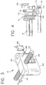
- Cam 326 may be rotated by pressing lever 224 (see figs. 2 and 4) which in turn rotates shaft 114 and thus cam 326.
- Half nut 322 is provided with projection 328, which is linked to disengage detector switch 330.
- disengage detector switch 330 When lever 224 is pressed, thus disengaging half nuts 322, 324, disengage detector switch 330 is activated. As long as half nut 322 is disengaged from lead screw 222, disengage detector switch 330 will be activated, causing output 64 to be high.
- Fig. 7 shows antisiphon catch detector 38 in detail.
- Antisiphon catch 20 is attached to shaft 442 which is in turn linked to lever 224 (Fig. 2) via cam 443 so that antisiphon catch 20 can be disengaged.
- tab 444 Also attached to shaft 442 is tab 444.
- Tab 444 moves in concert with antisiphon catch 20.
- Tab 444 is provided with ears 446 and 448 spaced apart by space 450.
- Detector 452 is an optical detector available from Optek Technology, Inc. of Carrollton, Texas under part number OPB860 or OPB870.
- detector 452 When antisiphon catch is correctly positioned on plunger 18, detector 452 is aligned with space 450 and is inactive.
- ears 446 or 448 interrupt the light beam in detector 452 and detector is activated and produces output 62.
- the electronics of disengage detector are shown in Fig. 8l.
- Outputs 62, 64 and 66 are sequentially latched to microprocessor 46 by latch 68 (Fig. 8f).
- the latching of outputs 62, 64 and 66 provides a power saving since 36, 38, 40, 42 need only be powered while they are monitored.
- the sampled power supply and latching of outputs 62, 64 and 66 are controlled by microprocessor 46 by means of a program stored in EPROM 50. The precise details of how this is accomplished are not material to this invention.
- the microprocessor When the microprocessor detects that any one of outputs 62, 64 and 66 has gone high, it generates a signal to activate the corresponding indicium on display panel 24. Thus, when output 62 (the antisiphon catch detector output) goes high, second indicium 32 is activated, when output 64 (the disengage detector output) goes high, third indicium 34 is activated and when output 66 (the syringe clamp detector output) goes high, first indicium 30 is activated. The user is thus alerted of an error condition at any one of antisiphon catch 20, syringe clamp 16 or disengage mechanism 44 by means of a display showing the location on the syringe at which the error condition occurs.
Description
- This invention relates to the field of syringe pumps. In particular, it relates to displays for indicating operating conditions in syringe pumps.
- A syringe pump is a device for pumping fluid from a syringe into a patient. It typically comprises a housing to which a syringe is secured and a mechanism for pushing the plunger of the syringe to expel the fluid from the syringe, thus infusing the fluid into the patient. In the course of the operation of the syringe pump, certain conditions may arise at various parts of the pump. Using this invention, the user is informed of error conditions in the syringe pump by means of indicia on a display.
- EP-A-0 314 880 describes a syringe pump according to the preamble of
claim 1. - In such syringe pumps, according to the prior art, the user is informed of error conditions by means of messages displayed on the syringe pump control panel. These messages have been in the form of codes or flashing indicia. The applicants are unaware of any prior art syringe pump which has a single graphical representation of a syringe with indicia of all detected error conditions on that syringe and at points corresponding to the points at which the error conditions have arisen.
- The object of the present invention is to provide a syringe pump which allows a user to identify in a simple and easy way the location of error conditions.
- The invention is defined by the features of
claim 1. Improvements of this syringe pump are specified in the dependent claims. - According to the claims the syringe pump includes the following components: the syringe pump is housed in a housing which contains the drive mechanism for pushing the plunger of the syringe. The syringe is secured to the housing by means of a syringe clamp. In order to ensure that the syringe is securely held in place during the operation of the pump, the clamp is provided with a detector which detects the position of the clamp. The detector produces an electrical signal if the clamp is not properly positioned.
- The pump also may have a mechanism for holding the plunger in place, so that it cannot move independently of the pusher, thus preventing fluid from being siphoned from the syringe. This anti-siphon device is also provided with an electronic sensor which produces an electrical signal if the anti-siphon device is not properly positioned.
- The pusher may be driven by means of a motor driven lead screw and a half nut which engages the lead screw. In order to facilitate the positioning of the pusher relative to the syringe, the half nut can be disengaged from the lead screw. A transducer is provided to detect whether or not the half nut is engaged with the lead screw. The pump also has a mechanism for detecting the position of the syringe plunger relative to the barrel. An indicium is activated when the plunger has fully entered the barrel.
- The syringe pump has a display for alerting the user to error conditions arising at all or some of the points described above. The display is in the form of a graphical representation of a syringe. The graphical representation of the syringe has indicia located at the points on the graphical representation which generally correspond to the points on the actual syringe at which the error conditions described above may occur. Thus the display has indicia at all or some the following points: The point on the syringe barrel at which the clamp holds the barrel in place; the point on the plunger at which the antisiphon device engages the plunger; and the point on the plunger at which the plunger makes contact with the syringe pusher. When an error condition arises at any of the above-identified points on the actual syringe, the corresponding indicium on the graphical representation will be activated.
- The display also has an indicium at a position on the graphical representation corresponding to the point at which the stopper of the syringe plunger resides when the syringe plunger has fully entered the syringe barrel. When the plunger has fully entered the barrel of the syringe, the indicium will be activated.
- Thus the user is provided with a simple, easy to read means for identifying the location of error conditions and the end of the infusion cycle in the syringe pump.
-
- Fig. 1 is a perspective view of a syringe pump embodying the invention;
- Fig. 2 is a perspective view of the drive mechanism of the syringe pump;
- Fig. 3 is a perspective view of the lead screw and half nut mechanism inside pusher block of the syringe pump;
- Fig. 4 is a cross sectional view of the pusher mechanism of the syringe pump;
- Fig. 5 is a perspective view of the pusher disc and force transducer;
- Fig. 6 is a perspective view of the antisiphon catch detector.
- Fig. 7 is a block diagram of the electronic components of the invention; and
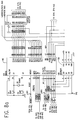
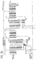
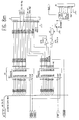
- Fig. 8a-m are schematic diagrams of the main electronic components of the invention.
- A
syringe pump 8 embodying the invention is shown in Fig. 1.Housing 10 supportssyringe barrel 12,pusher 14 andsyringe clamp 16.Syringe clamp 16 holdssyringe barrel 12 in place onhousing 10. Plunger 18 is pushed bypusher 14 which is driven by an electric motor via a lead screw (see Fig. 2). - Pusher 14 is provided with
antisiphon catch 20 which engagesflange 18a ofplunger 18, thus preventingplunger 18 from moving independently ofpusher 14. Pusher 14 is also provided withpressure plate 22 for pushing directly againstflange 18a thereby pumping fluid fromsyringe barrel 12. - Fig. 2 shows the chassis and mechanical components of
pump 8.Chassis 226 carriesmotor 230 andlead screw 222.Motor 230drives lead screw 222 viagear assembly 231. Pusher 14 is driven by the interaction ofpusher block 228 withlead screw 222. Pusher block containshalf nuts - Pusher
block 228 carriesrack 234 such thatrack 234 moves in unison withpusher block 228.Rack 234 is linked viapinion 233 torotary potentiometer 232. Thus aspusher 14 pushesplunger 18, due to the movement ofpusher block 228, the position ofpusher block 228 and henceplunger 18 is sensed byrotary potentiometer 232. The output ofrotary potentiometer 232 indicates the position ofplunger 18.Rotary potentiometer 232 is a five turn rotary potentiometer of 1Kohm impedance, 0.25W power rating and a linearity better than 0.25% of full scale. -
Display panel 24 contains controls for adjusting various parameters of the pump.Display panel 24 also contains graphic 26 which is a graphical representation ofsyringe barrel 12 andplunger 18. Graphic 26 is made up of anoutline 25 of the syringe, showing the barrel and the plunger.Graphic 26 also includes first, second andthird indicia direction arrows occlusion indicator 29b.First indicium 30 is located at a point on graphic 26 corresponding to the point onsyringe barrel 12 at which clamp 16 holdssyringe barrel 12 in place.Second indicium 32 is located at a point on graphic 26 which corresponds to the point onplunger 18 at whichantisiphon catch 20 makes contact withplunger 18.Third indicium 34 is located at a point on the graphic which corresponds to the point at whichpusher 14 pushes flange 18a ofplunger 18, i.e.pressure plate 22. - First, second and
third indicia syringe clamp 16,antisiphon catch 20 andhalf nut 322. Thus, when an error condition is detected at any one of the aforementioned, the corresponding indicium will indicate the error condition on graphic 26. End of infusion indicator (fourth indicium 28) is linked torotary potentiometer 232. Whenplunger 18 has fully enteredsyringe barrel 12,fourth indicium 28 will be activated to indicate the end of the infusion cycle. - End of
infusion indicator 28 is at a position on graphic 26 corresponding to the position ofsyringe plunger 18 when the end of the infusion is reached.Direction arrows syringe barrel 12.Occlusion indicator 29b points in the direction of the force resulting from the occurrence of an occlusion in the delivery line. - Fig. 7 is a block diagram showing the main electronic components of the invention. Five transducers are provided to detect the parameters of the syringe pump which are displayed. The transducers are:
position sensor 35,force transducer 36,antisiphon catch detector 38,disengage detector 40 andsyringe clamp detector 42. The outputs of thesetransducers central processing unit 45 via various signal processing or latching modules which will be described in detail herein. - Schematic diagrams of the various modules are shown in Figs. 8a-m. The values and types of the components are indicated on the schematic diagrams.
-
Central processing unit 45 comprises microprocessor 46 (Fig. 8a) with random access memory 53 (Fig. 8c), watchdog 48 (Fig. 8b), EPROM 50 (Fig. 8a) and EEPROM 52 (Fig. 8c).Watchdog 48monitors microprocessor 46 to ensure its proper operation.EEPROM 52 contains data concerning the parameters of each of the various types of syringes which may be used in the pump, such as brand, size and model of syringe, volume of syringe, number of motor steps per ml infused, "hard-height" (i.e. the distance from the plunger flange to the open end of syringe barrel when the plunger has fully entered the barrel, the syringe frictional force in gF (i.e. Ff) and the syringe pressure under a 5kg load in millibars (i.e. Pc).EPROM 50 contains a software program which controls the operation of the syringe pump. - The output of
force transducer 36 is conditioned by signal conditioning circuit 54 (Fig. 8d), which converts the output offorce transducer 36 into a form suitable for input into analog to digital converter 56 (Fig. 8e).Output 61 ofposition sensor 35 is conditioned bysignal conditioning circuit 55 and is then also fed into analog todigital converter 56. Analog todigital converter 56 digitizes the analog outputs 60 and 61 and producesserial output 58 which is in turn fed into input port ofmicroprocessor 46. -
EEPROM 52 contains data representing the outputs of position sensor (i.e. "hard-height" of the syringe) corresponding to the points at whichplunger 18 has fully enteredsyringe barrel 12 for various types of syringe. - When
antisiphon catch 20 is disengaged,antisiphon catch detector 38 produces digital output 62 (See Fig. 8i). Similarly the opening ofdisengage mechanism 44 causes disengagedetector 40 to produce an output 64 (Fig. 8f) and the opening ofsyringe clamp 16 causes syringe clamp detector (Fig. 8h) to produce anoutput 66. Eachoutput central processing unit 45 via latch 68 (Fig. 8f). -
Microprocessor 46 causes error conditions atclamp 16, disengage mechanism andantisiphon catch 20 to be displayed on display panel 24 (Fig. 8g).Display panel 24 comprisesgraphical representation 26 which in turn comprisessyringe outline 25,first indicium 30 indicating an error condition atsyringe clamp 16,second indicium 32 which indicates an error condition atantisiphon catch 20 andthird indicium 34 which indicates thatdisengage 44 mechanism is disengaged. - In Fig. 8j, indicia 30, 32 and 34 correspond to light emitting diodes LD2, LD3 and LD16 respectively.
Indicia microprocessor 46 when error conditions arise.Indicia - Figs. 5 shows
force transducer 36 in greater detail.Force transducer 36 is made up of four strain gauges in a wheatstone bridge configuration. The bridge has an impedance of 350 ohms or 1 Kohm with a tolerance of +/- 15%. The range of force measurements is 0 to 150 N. The bridge sensitivity is 1.7 mV/V to 2.4 mV/V under a load of 150 N at 20 degrees centigrade. The bridge is powered intermittently under the control of microprocessor 46 (line CDANA in Figs. 8a and 8d) in order to conserve energy. - Strain gauges 112 are glued onto
beam 114. When force is applied topressure plate 22,beam 114 flexes, causingstrain gauges 112 to distort and produceoutput 60. -
Output 60 offorce transducer 36 is fed into conditioning module 54 (Fig. 8d) and thereafter into analog todigital converter 56 which converts the conditioned output intoserial output 58.Serial output 58 is then fed into input ofmicroprocessor 46. - The
output 61 ofposition sensor 35 is similarly conditioned bysignal conditioning circuit 55 and fed into analog todigital converter 56. - Resident in
EPROM 50 is a software program formicroprocessor 46 which calculates the pressure insidesyringe 12 continuously as the force on theplunger 18 is measured byforce transducer 36. Certain parameters which are used by the program to calculate the pressure in the syringe and stored inEEPROM 52. Sincesyringe pump 8 is programmable to accommodate various types of syringe, a set of parameters for each type of syringe, is stored inEEPROM 52. - The parameters stored in
EEPROM 52 include: - Ff = average frictional force between the syringe plunger and the syringe barrel at null (atmospheric) pressure.
- Pc = the pressure in the syringe when a calibration force is applied to the plunger. The calibration force is typically 5kgF which leads to a value of Pc around 0.7 bar, a usual threshold for infusion pumps.
- Fc = the force with which the plunger is loaded to obtain a pressure of Pc in the syringe.
- The program in
EPROM 50 is used bymicroprocessor 46 to calculate the pressure in the syringe.Microprocessor 46 then compares the calculated pressure with the pressure threshold selected by the user. If the calculated pressure exceeds the threshold, an occlusion alarm is generated bymicroprocessor 46. - The algorithm for calculating the pressure in the syringe is:

force transducer 36 and Fc, Ff and Pc are the parameters defined above. - The main advantages of this formula over the traditional formula described in the BACKGROUND section above are (1) it is not highly dependent on the frictional force in the syringe which is known to vary with pressure and (2) that the cross-sectional area of the syringe need not be determined. Rather, the pressure in the syringe is calculated using parameters which are easy to determine empirically.
- The position of
plunger 18 as detected byposition sensor 35 is read bymicroprocessor 46 and compared with the "hard-height" stored inEEPROM 52 for the particular type of syringe being used. If the position detected is the same as the hard-height,microprocessor 46 actuates indicium 280 (LD14 in Fig. 8j, driven by transistors Q14 and Q2 in Fig. 8h). -
Clamp 16 comprises a spring loaded shaft which enablesclamp 16 to be lifted and turned so that the syringe can be placed and removed.Clamp 16 is provided with a syringe clamp detector 42 (Fig. 8h) which detects whether or not clamp 16 is properly placed. Whenclamp 16 is properly placed,output 66 is low.Detector 42 comprisesoptical detector 42a, and associated circuitry.Detector 42 is powered by a sampled power supply controlled byCPU 46. - Disengage mechanism 44 (Fig. 3) comprises
half nuts lead screw 222 so that pusher block 228 which holds half nuts 322, 324 (Fig. 2) may be separated by the rotation ofcam 326.Cam 326 may be rotated by pressing lever 224 (see figs. 2 and 4) which in turn rotatesshaft 114 and thuscam 326.Half nut 322 is provided withprojection 328, which is linked to disengagedetector switch 330. - When
lever 224 is pressed, thus disengaginghalf nuts detector switch 330 is activated. As long ashalf nut 322 is disengaged fromlead screw 222, disengagedetector switch 330 will be activated, causingoutput 64 to be high. - Fig. 7 shows
antisiphon catch detector 38 in detail.Antisiphon catch 20 is attached toshaft 442 which is in turn linked to lever 224 (Fig. 2) viacam 443 so thatantisiphon catch 20 can be disengaged. Also attached toshaft 442 istab 444.Tab 444 moves in concert withantisiphon catch 20.Tab 444 is provided withears space 450.Detector 452 is an optical detector available from Optek Technology, Inc. of Carrollton, Texas under part number OPB860 or OPB870. When antisiphon catch is correctly positioned onplunger 18,detector 452 is aligned withspace 450 and is inactive. When antisiphon catch is improperly placed, i.e. is in either position A or position B,ears detector 452 and detector is activated and producesoutput 62. The electronics of disengage detector are shown in Fig. 8l. -
Outputs microprocessor 46 by latch 68 (Fig. 8f). The latching ofoutputs outputs microprocessor 46 by means of a program stored inEPROM 50. The precise details of how this is accomplished are not material to this invention. - When the microprocessor detects that any one of
outputs display panel 24. Thus, when output 62 (the antisiphon catch detector output) goes high,second indicium 32 is activated, when output 64 (the disengage detector output) goes high,third indicium 34 is activated and when output 66 (the syringe clamp detector output) goes high,first indicium 30 is activated. The user is thus alerted of an error condition at any one ofantisiphon catch 20,syringe clamp 16 ordisengage mechanism 44 by means of a display showing the location on the syringe at which the error condition occurs.
Claims (10)
- A syringe pump (8) for pumping fluid from a syringe having a barrel (12) and a plunger (18), the plunger having a flange (18a), the syringe pump comprising:- a housing (10);- a pusher (14) for pushing the plunger (18);- clamp means (16) for engaging the syringe barrel (12) and holding the syringe barrel (12) in a stationary position relative to the housing (10);- clamp detector means (42) for detecting whether or not the syringe is properly held in position relative to the housing (10) by the clamp means (16) and for producing an output indicative of whether the syringe is properly held in position relative to the housing (10);- anti-siphon means (20) for engaging the plunger (18) and holding the plunger (18) stationary relative to the pusher (14), thereby preventing the plunger (18) from moving independently of the pusher (14);- anti-siphon detector means (38) for detecting whether the plunger (18) is properly engaged by the anti-siphon means (20) and for producing an output indicative of whether the plunger (18) is properly engaged by the anti-siphon means (20),
characterised in that it comprises:- a display (24) made up of an outline (25) showing the syringe barrel (12) and the plunger (18), a first indicium means (30), consisting of a light emitting diode, located at a point on the display (24) generally corresponding to the position on the syringe pump barrel, where the clamp engages the syringe barrel (12) and a second indicium means (32), consisting of a light emitting diode, located at a point on the display (24) generally corresponding to the position on the plunger (18) where the anti-siphon means (20) engages the plunger (18);- electronic circuitry (45) for transmitting the outputs (66, 62) of the clamp detector means (42) and the anti-siphon detector means (38) respectively to the first and second indicia means (30, 32), whereby said first Indicium means (30) indicate whether or not the syringe is properly held relative to the housing (10) and said second indicium means (32) indicate whether or not the plunger (18) is properly engaged by the anti-siphon means (20). - The syringe pump of claim 1, further comprising:- drive means (230, 222, 238) for driving the pusher (14);- disengage means (44) for engaging and disengaging the drive means ;- disengage detector means (40) for detecting whether the drive means (230, 222, 238) is engaged or disengaged and for producing an output (64) indicative of whether the drive means (230, 222, 238) is engaged or disengaged,
wherein the display (24) further comprises a third indicium means (34) for indicating the output (64) of the disengage detector means (40), such that the third indicium means (34) is located at a point on the display (24) corresponding to the position on the syringe plunger (18) at which the plunger makes contact with the syringe; and
wherein the electronic circuitry further comprises means for transmitting the output (64) of the disengage detector means (40) to the third indicium means (34). - The syringe pump of claim 1, wherein the plunger (18) comprises a stopper and further comprising means for determining whether the plunger (18) has fully entered the barrel (12) and wherein the display (24) comprises a fourth indicium means (28) for indicating whether the plunger (18) has fully entered the barrel, the fourth indicium means (28) being located on the display (24) at a point corresponding to the point in the barrel (12) at which the stopper of the plunger (18) is located when the plunger (18) has fully entered the barrel (12).
- The syringe pump of claim 1, wherein the electronic circuitry comprises a microprocessor (46).
- The syringe pump of claim 2, wherein the third indicium means (34) is located adjacent a point on the display (24) generally corresponding to the back of the flange (18a) of the plunger (18).
- The syringe pump of claim 1, wherein the first indicium means (30) is activated when the syringe is not properly held in position on the housing (10) by the clamp means (16).
- The syringe pump of claim 1, wherein the second indicium means (32) is activated when the plunger is not properly engaged by the anti-siphon means (20).
- The syringe pump of claim 2, wherein the third indicium (34) is activated when the drive means is disengaged.
- The syringe pump of claim 2, wherein the drive means comprises a lead screw (222) and a half nut (322, 324), the half nut engaging the lead screw (222) when the drive means is engaged.
- The syringe pump of claim 9, wherein the third indicium means (34) lights up when the half nut does not engage the lead screw.
Applications Claiming Priority (2)
| Application Number | Priority Date | Filing Date | Title |
|---|---|---|---|
| US950385 | 1992-09-23 | ||
| US07/950,385 US5254096A (en) | 1992-09-23 | 1992-09-23 | Syringe pump with graphical display or error conditions |
Publications (3)
| Publication Number | Publication Date |
|---|---|
| EP0589328A2 EP0589328A2 (en) | 1994-03-30 |
| EP0589328A3 EP0589328A3 (en) | 1994-06-22 |
| EP0589328B1 true EP0589328B1 (en) | 1997-11-12 |
Family
ID=25490372
Family Applications (1)
| Application Number | Title | Priority Date | Filing Date |
|---|---|---|---|
| EP93114709A Expired - Lifetime EP0589328B1 (en) | 1992-09-23 | 1993-09-14 | Syringe pump with graphical display of error conditions |
Country Status (4)
| Country | Link |
|---|---|
| US (1) | US5254096A (en) |
| EP (1) | EP0589328B1 (en) |
| JP (1) | JP2610385B2 (en) |
| DE (1) | DE69315158T2 (en) |
Families Citing this family (298)
| Publication number | Priority date | Publication date | Assignee | Title |
|---|---|---|---|---|
| GB9309151D0 (en) * | 1993-05-04 | 1993-06-16 | Zeneca Ltd | Syringes and syringe pumps |
| US5882338A (en) * | 1993-05-04 | 1999-03-16 | Zeneca Limited | Syringes and syringe pumps |
| US5533981A (en) * | 1994-10-06 | 1996-07-09 | Baxter International Inc. | Syringe infusion pump having a syringe plunger sensor |
| US6109880A (en) * | 1994-10-31 | 2000-08-29 | Saes Pure Gas, Inc. | Getter pump module and system including focus shields |
| US5911560A (en) * | 1994-10-31 | 1999-06-15 | Saes Pure Gas, Inc. | Getter pump module and system |
| US5685963A (en) * | 1994-10-31 | 1997-11-11 | Saes Pure Gas, Inc. | In situ getter pump system and method |
| US5972183A (en) * | 1994-10-31 | 1999-10-26 | Saes Getter S.P.A | Getter pump module and system |
| US6142742A (en) * | 1994-10-31 | 2000-11-07 | Saes Pure Gas, Inc. | Getter pump module and system |
| GB9422082D0 (en) * | 1994-11-02 | 1994-12-21 | Zeneca Ltd | Reservoirs and delivery devices |
| IL116765A0 (en) * | 1995-01-17 | 1996-05-14 | Therakos Inc | On-line drug delivery system in extracorporeal therapy |
| US5814015A (en) * | 1995-02-24 | 1998-09-29 | Harvard Clinical Technology, Inc. | Infusion pump for at least one syringe |
| US5647853A (en) * | 1995-03-03 | 1997-07-15 | Minimed Inc. | Rapid response occlusion detector for a medication infusion pump |
| US5637093A (en) * | 1995-03-06 | 1997-06-10 | Sabratek Corporation | Infusion pump with selective backlight |
| US5989221A (en) * | 1995-10-20 | 1999-11-23 | Pharmacia & Upjohn Ab | Arrangement in electronically controlled injection devices |
| SE9503685D0 (en) * | 1995-10-20 | 1995-10-20 | Pharmacia Ab | Arrangement in electronically controlled injection devices |
| DE69522814T2 (en) * | 1995-12-19 | 2002-04-25 | Fresenius Ag | Modular system, in particular for biomedical applications, a unit and a communication system therefor |
| ATE494027T1 (en) * | 1996-03-12 | 2011-01-15 | Novo Nordisk As | INJECTION DEVICE WITH ELECTRONIC DISPLAY OF THE SELECTED DOSE |
| US6558900B2 (en) * | 1996-07-12 | 2003-05-06 | Emory University | Regulation of apoptosis and in vitro model for studies thereof |
| US5876378A (en) * | 1996-09-20 | 1999-03-02 | Mbadugha; Joseph O. | Apparatus and method for injecting liquids into patients |
| EP1595562A3 (en) * | 1997-01-10 | 2006-08-02 | Japan Servo Co. Ltd. | Liquid infusion apparatus |
| US6022337A (en) * | 1997-09-04 | 2000-02-08 | Herbst; Walter | Dental anesthetic and delivery injection unit |
| JP3864523B2 (en) * | 1997-12-22 | 2007-01-10 | 富士電機ホールディングス株式会社 | Syringe pump pusher clamp mechanism |
| US20020173748A1 (en) * | 1998-10-29 | 2002-11-21 | Mcconnell Susan | Reservoir connector |
| EP2223713A3 (en) * | 1998-10-29 | 2015-02-18 | Medtronic MiniMed, Inc. | Connection interface between a reservoir and an infusion pump |
| US7193521B2 (en) * | 1998-10-29 | 2007-03-20 | Medtronic Minimed, Inc. | Method and apparatus for detecting errors, fluid pressure, and occlusions in an ambulatory infusion pump |
| US6800071B1 (en) * | 1998-10-29 | 2004-10-05 | Medtronic Minimed, Inc. | Fluid reservoir piston |
| US6248093B1 (en) | 1998-10-29 | 2001-06-19 | Minimed Inc. | Compact pump drive system |
| GB9909654D0 (en) | 1999-04-28 | 1999-06-23 | Smiths Industries Plc | Syringe pump |
| GB9910985D0 (en) * | 1999-05-12 | 1999-07-14 | Smiths Industries Plc | Syringe pumps |
| US6423035B1 (en) | 1999-06-18 | 2002-07-23 | Animas Corporation | Infusion pump with a sealed drive mechanism and improved method of occlusion detection |
| WO2001008727A1 (en) | 1999-07-30 | 2001-02-08 | Medrad, Inc. | Injector systems and syringe adapters for use therewith |
| US7063684B2 (en) * | 1999-10-28 | 2006-06-20 | Medtronic Minimed, Inc. | Drive system seal |
| US6485461B1 (en) | 2000-04-04 | 2002-11-26 | Insulet, Inc. | Disposable infusion device |
| MXPA02011395A (en) * | 2000-05-18 | 2003-04-25 | Dentsply Int Inc | Fluid material dispensing syringe. |
| US6669669B2 (en) | 2001-10-12 | 2003-12-30 | Insulet Corporation | Laminated patient infusion device |
| CA2771723C (en) * | 2000-09-08 | 2016-03-29 | Insulet Corporation | Devices, systems and methods for patient infusion |
| DE60119354T2 (en) * | 2000-10-10 | 2007-04-19 | Dentsply International Inc. | Syringe for dental anesthesia |
| US6572604B1 (en) | 2000-11-07 | 2003-06-03 | Baxter International Inc. | Occlusion detection method and system for ambulatory drug infusion pump |
| DE60126325T2 (en) | 2000-11-09 | 2007-11-08 | Insulet Corp., Beverly | DEVICE FOR THE TRANSCUTANEOUS DISPOSAL OF MEDICAMENTS |
| ATE311811T1 (en) | 2000-12-21 | 2005-12-15 | Insulet Corp | REMOTE CONTROL MEDICAL DEVICE |
| CN1556716A (en) | 2001-02-22 | 2004-12-22 | ���Ͽع�����˾ | Modular infusion device and method |
| US8034026B2 (en) | 2001-05-18 | 2011-10-11 | Deka Products Limited Partnership | Infusion pump assembly |
| EP1815879A3 (en) | 2001-05-18 | 2007-11-14 | Deka Products Limited Partnership | Infusion set for a fluid pump |
| US6985870B2 (en) | 2002-01-11 | 2006-01-10 | Baxter International Inc. | Medication delivery system |
| US10173008B2 (en) | 2002-01-29 | 2019-01-08 | Baxter International Inc. | System and method for communicating with a dialysis machine through a network |
| US8775196B2 (en) | 2002-01-29 | 2014-07-08 | Baxter International Inc. | System and method for notification and escalation of medical data |
| US6692457B2 (en) | 2002-03-01 | 2004-02-17 | Insulet Corporation | Flow condition sensor assembly for patient infusion device |
| US6830558B2 (en) | 2002-03-01 | 2004-12-14 | Insulet Corporation | Flow condition sensor assembly for patient infusion device |
| US6656158B2 (en) | 2002-04-23 | 2003-12-02 | Insulet Corporation | Dispenser for patient infusion device |
| US6656159B2 (en) | 2002-04-23 | 2003-12-02 | Insulet Corporation | Dispenser for patient infusion device |
| US6960192B1 (en) | 2002-04-23 | 2005-11-01 | Insulet Corporation | Transcutaneous fluid delivery system |
| US8234128B2 (en) | 2002-04-30 | 2012-07-31 | Baxter International, Inc. | System and method for verifying medical device operational parameters |
| US6723072B2 (en) | 2002-06-06 | 2004-04-20 | Insulet Corporation | Plunger assembly for patient infusion device |
| US6997905B2 (en) | 2002-06-14 | 2006-02-14 | Baxter International Inc. | Dual orientation display for a medical device |
| US7018361B2 (en) | 2002-06-14 | 2006-03-28 | Baxter International Inc. | Infusion pump |
| US7018360B2 (en) | 2002-07-16 | 2006-03-28 | Insulet Corporation | Flow restriction system and method for patient infusion device |
| US7128727B2 (en) | 2002-09-30 | 2006-10-31 | Flaherty J Christopher | Components and methods for patient infusion device |
| US7144384B2 (en) | 2002-09-30 | 2006-12-05 | Insulet Corporation | Dispenser components and methods for patient infusion device |
| US20040133166A1 (en) * | 2002-11-22 | 2004-07-08 | Minimed Inc. | Methods, apparatuses, and uses for infusion pump fluid pressure and force detection |
| JP4286019B2 (en) * | 2003-02-04 | 2009-06-24 | 株式会社根本杏林堂 | Chemical injection system |
| US20040193325A1 (en) * | 2003-03-25 | 2004-09-30 | David Bonderud | Method and apparatus to prevent medication error in a networked infusion system |
| AU2004232858B2 (en) | 2003-04-23 | 2009-07-09 | Mannkind Corporation | Hydraulically actuated pump for long duration medicament administration |
| US7311879B2 (en) * | 2003-08-14 | 2007-12-25 | Hodson Steve J | Syringe pump |
| US8422413B2 (en) * | 2003-09-18 | 2013-04-16 | Dentsply International Inc. | Process and device for the wireless transmission of dental process data |
| PL1715904T3 (en) * | 2004-02-18 | 2016-01-29 | Ares Trading Sa | Hand-held electronically controlled injection device for injecting liquid medications |
| ITMO20040082A1 (en) | 2004-04-13 | 2004-07-13 | Gambro Lundia Ab | CONNECTOR FOR A FLUID LINE OF AN EXTACORPOREO CIRCUIT |
| ITMO20040085A1 (en) | 2004-04-20 | 2004-07-20 | Gambro Lundia Ab | INFUSION DEVICE FOR MEDICAL FLUIDS. |
| WO2006014425A1 (en) | 2004-07-02 | 2006-02-09 | Biovalve Technologies, Inc. | Methods and devices for delivering glp-1 and uses thereof |
| GB0422884D0 (en) * | 2004-10-15 | 2004-11-17 | Zi Medical Plc | Syringe driver monitoring means |
| US7775966B2 (en) | 2005-02-24 | 2010-08-17 | Ethicon Endo-Surgery, Inc. | Non-invasive pressure measurement in a fluid adjustable restrictive device |
| US20060200085A1 (en) * | 2005-02-15 | 2006-09-07 | Philip Watts | Tissue transfer cannula and connectors |
| US7699770B2 (en) | 2005-02-24 | 2010-04-20 | Ethicon Endo-Surgery, Inc. | Device for non-invasive measurement of fluid pressure in an adjustable restriction device |
| US7658196B2 (en) | 2005-02-24 | 2010-02-09 | Ethicon Endo-Surgery, Inc. | System and method for determining implanted device orientation |
| US7775215B2 (en) | 2005-02-24 | 2010-08-17 | Ethicon Endo-Surgery, Inc. | System and method for determining implanted device positioning and obtaining pressure data |
| US8066629B2 (en) | 2005-02-24 | 2011-11-29 | Ethicon Endo-Surgery, Inc. | Apparatus for adjustment and sensing of gastric band pressure |
| US7927270B2 (en) | 2005-02-24 | 2011-04-19 | Ethicon Endo-Surgery, Inc. | External mechanical pressure sensor for gastric band pressure measurements |
| US8016744B2 (en) | 2005-02-24 | 2011-09-13 | Ethicon Endo-Surgery, Inc. | External pressure-based gastric band adjustment system and method |
| US9233203B2 (en) | 2005-05-06 | 2016-01-12 | Medtronic Minimed, Inc. | Medical needles for damping motion |
| US8277415B2 (en) | 2006-08-23 | 2012-10-02 | Medtronic Minimed, Inc. | Infusion medium delivery device and method with drive device for driving plunger in reservoir |
| US7905868B2 (en) | 2006-08-23 | 2011-03-15 | Medtronic Minimed, Inc. | Infusion medium delivery device and method with drive device for driving plunger in reservoir |
| US8137314B2 (en) * | 2006-08-23 | 2012-03-20 | Medtronic Minimed, Inc. | Infusion medium delivery device and method with compressible or curved reservoir or conduit |
| US20080097291A1 (en) * | 2006-08-23 | 2008-04-24 | Hanson Ian B | Infusion pumps and methods and delivery devices and methods with same |
| US8840586B2 (en) | 2006-08-23 | 2014-09-23 | Medtronic Minimed, Inc. | Systems and methods allowing for reservoir filling and infusion medium delivery |
| US8512288B2 (en) | 2006-08-23 | 2013-08-20 | Medtronic Minimed, Inc. | Infusion medium delivery device and method with drive device for driving plunger in reservoir |
| US20070049872A1 (en) * | 2005-07-01 | 2007-03-01 | Philip Watts | Syringe clip |
| CN1928760A (en) * | 2005-09-05 | 2007-03-14 | 高侨自动化科技股份有限公司 | Injection controlling device |
| US20070093755A1 (en) * | 2005-09-23 | 2007-04-26 | Koos David R | Cannula handle and storage system |
| US8852164B2 (en) | 2006-02-09 | 2014-10-07 | Deka Products Limited Partnership | Method and system for shape-memory alloy wire control |
| US8113244B2 (en) | 2006-02-09 | 2012-02-14 | Deka Products Limited Partnership | Adhesive and peripheral systems and methods for medical devices |
| CN103550846B (en) * | 2005-11-21 | 2018-02-06 | 阿西斯特医疗系统有限公司 | Medical fluid injection system |
| US11497846B2 (en) | 2006-02-09 | 2022-11-15 | Deka Products Limited Partnership | Patch-sized fluid delivery systems and methods |
| US11478623B2 (en) | 2006-02-09 | 2022-10-25 | Deka Products Limited Partnership | Infusion pump assembly |
| US11364335B2 (en) | 2006-02-09 | 2022-06-21 | Deka Products Limited Partnership | Apparatus, system and method for fluid delivery |
| US9492606B2 (en) | 2006-02-09 | 2016-11-15 | Deka Products Limited Partnership | Apparatus, system and methods for an infusion pump assembly |
| JP2009532117A (en) | 2006-03-30 | 2009-09-10 | ヴァレリタス,エルエルシー | Multi-cartridge fluid dispensing device |
| US8870742B2 (en) | 2006-04-06 | 2014-10-28 | Ethicon Endo-Surgery, Inc. | GUI for an implantable restriction device and a data logger |
| US8152710B2 (en) | 2006-04-06 | 2012-04-10 | Ethicon Endo-Surgery, Inc. | Physiological parameter analysis for an implantable restriction device and a data logger |
| US7811262B2 (en) | 2006-08-23 | 2010-10-12 | Medtronic Minimed, Inc. | Systems and methods allowing for reservoir filling and infusion medium delivery |
| US7828764B2 (en) | 2006-08-23 | 2010-11-09 | Medtronic Minimed, Inc. | Systems and methods allowing for reservoir filling and infusion medium delivery |
| US7794434B2 (en) | 2006-08-23 | 2010-09-14 | Medtronic Minimed, Inc. | Systems and methods allowing for reservoir filling and infusion medium delivery |
| US7682338B2 (en) | 2006-08-23 | 2010-03-23 | Medtronic Minimed, Inc. | Infusion medium delivery system, device and method with needle inserter and needle inserter device and method |
| US8399823B2 (en) * | 2006-12-22 | 2013-03-19 | Swi Barak | Syringe movement mechanism and control system therefor |
| US8613725B2 (en) | 2007-04-30 | 2013-12-24 | Medtronic Minimed, Inc. | Reservoir systems and methods |
| US8434528B2 (en) | 2007-04-30 | 2013-05-07 | Medtronic Minimed, Inc. | Systems and methods for reservoir filling |
| US8323250B2 (en) | 2007-04-30 | 2012-12-04 | Medtronic Minimed, Inc. | Adhesive patch systems and methods |
| US8597243B2 (en) | 2007-04-30 | 2013-12-03 | Medtronic Minimed, Inc. | Systems and methods allowing for reservoir air bubble management |
| US7963954B2 (en) | 2007-04-30 | 2011-06-21 | Medtronic Minimed, Inc. | Automated filling systems and methods |
| US7959715B2 (en) | 2007-04-30 | 2011-06-14 | Medtronic Minimed, Inc. | Systems and methods allowing for reservoir air bubble management |
| CA2685474C (en) | 2007-04-30 | 2014-07-08 | Medtronic Minimed, Inc. | Reservoir filling, bubble management, and infusion medium delivery systems and methods with same |
| DE202007018843U1 (en) * | 2007-09-21 | 2009-10-01 | Iprm Intellectual Property Rights Management Ag | Position detecting device for detecting at least two positions |
| US20090093793A1 (en) | 2007-10-02 | 2009-04-09 | Yossi Gross | External drug pump |
| US10420880B2 (en) | 2007-10-02 | 2019-09-24 | West Pharma. Services IL, Ltd. | Key for securing components of a drug delivery system during assembly and/or transport and methods of using same |
| US7967795B1 (en) | 2010-01-19 | 2011-06-28 | Lamodel Ltd. | Cartridge interface assembly with driving plunger |
| US9656019B2 (en) | 2007-10-02 | 2017-05-23 | Medimop Medical Projects Ltd. | Apparatuses for securing components of a drug delivery system during transport and methods of using same |
| US9345836B2 (en) | 2007-10-02 | 2016-05-24 | Medimop Medical Projects Ltd. | Disengagement resistant telescoping assembly and unidirectional method of assembly for such |
| US8187163B2 (en) | 2007-12-10 | 2012-05-29 | Ethicon Endo-Surgery, Inc. | Methods for implanting a gastric restriction device |
| US8100870B2 (en) | 2007-12-14 | 2012-01-24 | Ethicon Endo-Surgery, Inc. | Adjustable height gastric restriction devices and methods |
| US8517990B2 (en) | 2007-12-18 | 2013-08-27 | Hospira, Inc. | User interface improvements for medical devices |
| US8142452B2 (en) | 2007-12-27 | 2012-03-27 | Ethicon Endo-Surgery, Inc. | Controlling pressure in adjustable restriction devices |
| US8377079B2 (en) | 2007-12-27 | 2013-02-19 | Ethicon Endo-Surgery, Inc. | Constant force mechanisms for regulating restriction devices |
| US10188787B2 (en) | 2007-12-31 | 2019-01-29 | Deka Products Limited Partnership | Apparatus, system and method for fluid delivery |
| US9456955B2 (en) | 2007-12-31 | 2016-10-04 | Deka Products Limited Partnership | Apparatus, system and method for fluid delivery |
| WO2009088956A2 (en) | 2007-12-31 | 2009-07-16 | Deka Products Limited Partnership | Infusion pump assembly |
| BR122019016154B8 (en) | 2007-12-31 | 2021-06-22 | Deka Products Lp | infusion pump set |
| US10080704B2 (en) | 2007-12-31 | 2018-09-25 | Deka Products Limited Partnership | Apparatus, system and method for fluid delivery |
| US8900188B2 (en) | 2007-12-31 | 2014-12-02 | Deka Products Limited Partnership | Split ring resonator antenna adapted for use in wirelessly controlled medical device |
| US8881774B2 (en) | 2007-12-31 | 2014-11-11 | Deka Research & Development Corp. | Apparatus, system and method for fluid delivery |
| US8986253B2 (en) | 2008-01-25 | 2015-03-24 | Tandem Diabetes Care, Inc. | Two chamber pumps and related methods |
| US8591395B2 (en) | 2008-01-28 | 2013-11-26 | Ethicon Endo-Surgery, Inc. | Gastric restriction device data handling devices and methods |
| US8192350B2 (en) | 2008-01-28 | 2012-06-05 | Ethicon Endo-Surgery, Inc. | Methods and devices for measuring impedance in a gastric restriction system |
| US8337389B2 (en) | 2008-01-28 | 2012-12-25 | Ethicon Endo-Surgery, Inc. | Methods and devices for diagnosing performance of a gastric restriction system |
| US7844342B2 (en) | 2008-02-07 | 2010-11-30 | Ethicon Endo-Surgery, Inc. | Powering implantable restriction systems using light |
| US8221439B2 (en) | 2008-02-07 | 2012-07-17 | Ethicon Endo-Surgery, Inc. | Powering implantable restriction systems using kinetic motion |
| US8114345B2 (en) | 2008-02-08 | 2012-02-14 | Ethicon Endo-Surgery, Inc. | System and method of sterilizing an implantable medical device |
| US8591532B2 (en) | 2008-02-12 | 2013-11-26 | Ethicon Endo-Sugery, Inc. | Automatically adjusting band system |
| US8057492B2 (en) | 2008-02-12 | 2011-11-15 | Ethicon Endo-Surgery, Inc. | Automatically adjusting band system with MEMS pump |
| US8034065B2 (en) | 2008-02-26 | 2011-10-11 | Ethicon Endo-Surgery, Inc. | Controlling pressure in adjustable restriction devices |
| US8233995B2 (en) | 2008-03-06 | 2012-07-31 | Ethicon Endo-Surgery, Inc. | System and method of aligning an implantable antenna |
| US8187162B2 (en) | 2008-03-06 | 2012-05-29 | Ethicon Endo-Surgery, Inc. | Reorientation port |
| JP5231872B2 (en) * | 2008-06-03 | 2013-07-10 | テルモ株式会社 | Syringe pump |
| EP2140894A1 (en) * | 2008-06-30 | 2010-01-06 | F.Hoffmann-La Roche Ag | Infusion device with optical status indicators |
| US8057679B2 (en) | 2008-07-09 | 2011-11-15 | Baxter International Inc. | Dialysis system having trending and alert generation |
| US10089443B2 (en) | 2012-05-15 | 2018-10-02 | Baxter International Inc. | Home medical device systems and methods for therapy prescription and tracking, servicing and inventory |
| JP5197212B2 (en) * | 2008-07-31 | 2013-05-15 | アトムメディカル株式会社 | Syringe pump |
| US7959598B2 (en) | 2008-08-20 | 2011-06-14 | Asante Solutions, Inc. | Infusion pump systems and methods |
| CA2954728C (en) | 2008-09-15 | 2019-03-26 | Deka Products Limited Partnership | Systems and methods for fluid delivery |
| US9393369B2 (en) | 2008-09-15 | 2016-07-19 | Medimop Medical Projects Ltd. | Stabilized pen injector |
| US8408421B2 (en) | 2008-09-16 | 2013-04-02 | Tandem Diabetes Care, Inc. | Flow regulating stopcocks and related methods |
| US8650937B2 (en) | 2008-09-19 | 2014-02-18 | Tandem Diabetes Care, Inc. | Solute concentration measurement device and related methods |
| WO2010041592A1 (en) * | 2008-10-06 | 2010-04-15 | テルモ株式会社 | Syringe pump |
| US8223028B2 (en) | 2008-10-10 | 2012-07-17 | Deka Products Limited Partnership | Occlusion detection system and method |
| US8262616B2 (en) | 2008-10-10 | 2012-09-11 | Deka Products Limited Partnership | Infusion pump assembly |
| US8708376B2 (en) | 2008-10-10 | 2014-04-29 | Deka Products Limited Partnership | Medium connector |
| US9180245B2 (en) | 2008-10-10 | 2015-11-10 | Deka Products Limited Partnership | System and method for administering an infusible fluid |
| US8016789B2 (en) | 2008-10-10 | 2011-09-13 | Deka Products Limited Partnership | Pump assembly with a removable cover assembly |
| US8267892B2 (en) | 2008-10-10 | 2012-09-18 | Deka Products Limited Partnership | Multi-language / multi-processor infusion pump assembly |
| US8066672B2 (en) | 2008-10-10 | 2011-11-29 | Deka Products Limited Partnership | Infusion pump assembly with a backup power supply |
| US8554579B2 (en) | 2008-10-13 | 2013-10-08 | Fht, Inc. | Management, reporting and benchmarking of medication preparation |
| US8105269B2 (en) | 2008-10-24 | 2012-01-31 | Baxter International Inc. | In situ tubing measurements for infusion pumps |
| US8378837B2 (en) * | 2009-02-20 | 2013-02-19 | Hospira, Inc. | Occlusion detection system |
| US8137083B2 (en) | 2009-03-11 | 2012-03-20 | Baxter International Inc. | Infusion pump actuators, system and method for controlling medical fluid flowrate |
| EP3760180A3 (en) | 2009-07-29 | 2021-01-20 | ICU Medical, Inc. | Fluid transfer devices and methods of use |
| CA2769030C (en) | 2009-07-30 | 2016-05-10 | Tandem Diabetes Care, Inc. | Infusion pump system with disposable cartridge having pressure venting and pressure feedback |
| US8157769B2 (en) | 2009-09-15 | 2012-04-17 | Medimop Medical Projects Ltd. | Cartridge insertion assembly for drug delivery system |
| US10071196B2 (en) | 2012-05-15 | 2018-09-11 | West Pharma. Services IL, Ltd. | Method for selectively powering a battery-operated drug-delivery device and device therefor |
| US10071198B2 (en) | 2012-11-02 | 2018-09-11 | West Pharma. Servicees IL, Ltd. | Adhesive structure for medical device |
| US8382447B2 (en) | 2009-12-31 | 2013-02-26 | Baxter International, Inc. | Shuttle pump with controlled geometry |
| US8348898B2 (en) | 2010-01-19 | 2013-01-08 | Medimop Medical Projects Ltd. | Automatic needle for drug pump |
| US9744300B2 (en) * | 2011-12-21 | 2017-08-29 | Deka Products Limited Partnership | Syringe pump and related method |
| JP5431985B2 (en) * | 2010-01-25 | 2014-03-05 | パナソニック株式会社 | Mouthpiece molding base material for dental treatment and its preforming method |
| EP2569031B1 (en) | 2010-05-10 | 2017-10-11 | Medimop Medical Projects Ltd. | Low volume accurate injector |
| US8567235B2 (en) | 2010-06-29 | 2013-10-29 | Baxter International Inc. | Tube measurement technique using linear actuator and pressure sensor |
| DE102011009908A1 (en) * | 2011-01-31 | 2012-08-02 | Fresenius Medical Care Deutschland Gmbh | Clamping holder for a syringe of a dosing device, dosing device and blood treatment device |
| US9731068B2 (en) * | 2011-03-16 | 2017-08-15 | Fresenius Vial Sas | Drive head for a syringe pump |
| USD702834S1 (en) | 2011-03-22 | 2014-04-15 | Medimop Medical Projects Ltd. | Cartridge for use in injection device |
| CA2836042C (en) | 2011-05-12 | 2019-04-02 | Medrad, Inc. | Fluid injection system having various systems for controlling an injection procedure |
| CA2844807C (en) | 2011-08-19 | 2022-07-26 | Hospira, Inc. | Systems and methods for a graphical interface including a graphical representation of medical data |
| US9814832B2 (en) | 2011-09-02 | 2017-11-14 | Unl Holdings Llc | Drive mechanism for drug delivery pumps with integrated status indication |
| EP2731642B1 (en) | 2011-09-02 | 2018-09-19 | UNL Holdings LLC | Insertion mechanism for a drug delivery pump |
| US8939935B2 (en) | 2011-09-02 | 2015-01-27 | Unitract Syringe Pty Ltd | Drive mechanism for drug delivery pumps with integrated status indication |
| US9707335B2 (en) | 2011-09-02 | 2017-07-18 | Unitract Syringe Pty Ltd | Drive mechanism for drug delivery pumps with integrated status indication |
| US11173244B2 (en) | 2011-09-02 | 2021-11-16 | Unl Holdings Llc | Drive mechanism for drug delivery pumps with integrated status indication |
| WO2013040032A1 (en) | 2011-09-13 | 2013-03-21 | Unitract Syringe Pty Ltd | Sterile fluid pathway connection to drug containers for drug delivery pumps |
| ES2675035T3 (en) * | 2011-10-14 | 2018-07-05 | Amgen, Inc | Injector and assembly method |
| US10022498B2 (en) | 2011-12-16 | 2018-07-17 | Icu Medical, Inc. | System for monitoring and delivering medication to a patient and method of using the same to minimize the risks associated with automated therapy |
| CA3075368C (en) | 2011-12-22 | 2023-07-11 | Icu Medical, Inc. | Fluid transfer devices and methods of use |
| WO2013115843A1 (en) | 2012-01-31 | 2013-08-08 | Medimop Medical Projects Ltd. | Time dependent drug delivery apparatus |
| US11524151B2 (en) | 2012-03-07 | 2022-12-13 | Deka Products Limited Partnership | Apparatus, system and method for fluid delivery |
| US10668213B2 (en) | 2012-03-26 | 2020-06-02 | West Pharma. Services IL, Ltd. | Motion activated mechanisms for a drug delivery device |
| US9072827B2 (en) | 2012-03-26 | 2015-07-07 | Medimop Medical Projects Ltd. | Fail safe point protector for needle safety flap |
| US9463280B2 (en) | 2012-03-26 | 2016-10-11 | Medimop Medical Projects Ltd. | Motion activated septum puncturing drug delivery device |
| JP6306566B2 (en) | 2012-03-30 | 2018-04-04 | アイシーユー・メディカル・インコーポレーテッド | Air detection system and method for detecting air in an infusion system pump |
| EP3549524B1 (en) | 2012-03-30 | 2023-01-25 | Insulet Corporation | Fluid delivery device with transcutaneous access tool, insertion mechanism and blood glucose monitoring for use therewith |
| CN102648877B (en) * | 2012-04-25 | 2015-01-07 | 中国人民解放军第四军医大学 | Digital adjustable microinjection method |
| CN102646353A (en) * | 2012-04-28 | 2012-08-22 | 徐州医学院 | Anesthesia operation simulation device |
| US9180242B2 (en) | 2012-05-17 | 2015-11-10 | Tandem Diabetes Care, Inc. | Methods and devices for multiple fluid transfer |
| EP2687592A1 (en) * | 2012-07-20 | 2014-01-22 | greenovation Biotech GmbH | Filtration of cell culture supernatants |
| ES2743160T3 (en) | 2012-07-31 | 2020-02-18 | Icu Medical Inc | Patient care system for critical medications |
| CA2881306A1 (en) | 2012-08-29 | 2014-03-06 | Unitract Syringe Pty Ltd | Controlled delivery drive mechanisms for drug delivery pumps |
| NZ739406A (en) | 2012-08-31 | 2019-07-26 | Baxter Corp Englewood | Medication requisition fulfillment system and method |
| SG11201502364PA (en) * | 2012-09-25 | 2015-05-28 | Namiki Precision Jewel Co Ltd | Syringe fixing mechanism for syringe pump |
| EP3453377A1 (en) | 2012-10-26 | 2019-03-13 | Baxter Corporation Englewood | Improved work station for medical dose preparation system |
| KR102078768B1 (en) | 2012-10-26 | 2020-02-19 | 백스터 코포레이션 잉글우드 | Improved image acquisition for medical dose preparation system |
| JP6401179B2 (en) | 2012-12-07 | 2018-10-03 | スミスズ メディカル エーエスディー,インコーポレイティド | Syringe characterization |
| KR101422832B1 (en) * | 2012-12-28 | 2014-07-30 | (주)피지오랩 | Syringe pump simulator |
| US9421323B2 (en) | 2013-01-03 | 2016-08-23 | Medimop Medical Projects Ltd. | Door and doorstop for portable one use drug delivery apparatus |
| CA2898585C (en) | 2013-01-25 | 2020-10-13 | Unitract Syringe Pty Ltd | Integrated sliding seal fluid pathway connection and drug containers for drug delivery pumps |
| USD723157S1 (en) | 2013-03-12 | 2015-02-24 | Unitract Syringe Pty Ltd | Drug delivery pump |
| US10357606B2 (en) | 2013-03-13 | 2019-07-23 | Tandem Diabetes Care, Inc. | System and method for integration of insulin pumps and continuous glucose monitoring |
| US9173998B2 (en) | 2013-03-14 | 2015-11-03 | Tandem Diabetes Care, Inc. | System and method for detecting occlusions in an infusion pump |
| US9011164B2 (en) | 2013-04-30 | 2015-04-21 | Medimop Medical Projects Ltd. | Clip contact for easy installation of printed circuit board PCB |
| US9889256B2 (en) | 2013-05-03 | 2018-02-13 | Medimop Medical Projects Ltd. | Sensing a status of an infuser based on sensing motor control and power input |
| KR101468073B1 (en) * | 2013-05-07 | 2014-12-11 | 주식회사 바이오넷 | Automatic syringe pump system and Display Method |
| WO2014190264A1 (en) | 2013-05-24 | 2014-11-27 | Hospira, Inc. | Multi-sensor infusion system for detecting air or an occlusion in the infusion system |
| ES2838450T3 (en) | 2013-05-29 | 2021-07-02 | Icu Medical Inc | Infusion set that uses one or more sensors and additional information to make an air determination relative to the infusion set |
| AU2014274122A1 (en) | 2013-05-29 | 2016-01-21 | Icu Medical, Inc. | Infusion system and method of use which prevents over-saturation of an analog-to-digital converter |
| CA3130345A1 (en) | 2013-07-03 | 2015-01-08 | Deka Products Limited Partnership | Apparatus, system and method for fluid delivery |
| WO2015002806A1 (en) * | 2013-07-03 | 2015-01-08 | Smiths Medical Asd, Inc. | Combination linear potentiometer and syringe thumbpress detection sensor and related systems and methods |
| CN104415426B (en) * | 2013-08-23 | 2019-04-16 | 席斌 | Disposable insulin infusion pump |
| WO2015077184A1 (en) | 2013-11-25 | 2015-05-28 | Icu Medical, Inc. | Methods and system for filling iv bags with therapeutic fluid |
| CN103721323A (en) * | 2013-12-31 | 2014-04-16 | 北京中金硅谷科技有限公司 | Injection pump with function of warning user about nearly-empty state or empty state |
| CN103691029B (en) * | 2013-12-31 | 2015-07-29 | 北京中金硅谷科技有限公司 | A kind of syringe pump that can show dose in syringe in real time |
| KR101502509B1 (en) * | 2014-01-13 | 2015-03-13 | 대화기기주식회사 | Syringe pump having auto calibration function and method of auto calibration in syringe pump |
| JP6636442B2 (en) | 2014-02-28 | 2020-01-29 | アイシーユー・メディカル・インコーポレーテッド | Infusion systems and methods utilizing dual wavelength optical in-pipe air detection |
| US10232109B2 (en) * | 2014-04-14 | 2019-03-19 | MultiDimension Technology Co., Ltd. | Mini lead screw pump utilizing a magnetoresistive sensor and manufacturing method thereof |
| AU2015266706B2 (en) | 2014-05-29 | 2020-01-30 | Icu Medical, Inc. | Infusion system and pump with configurable closed loop delivery rate catch-up |
| NZ727697A (en) | 2014-06-30 | 2022-05-27 | Baxter Corp Englewood | Managed medical information exchange |
| JP6713467B2 (en) | 2014-09-29 | 2020-06-24 | ユーエヌエル ホールディングス エルエルシーUNL Holdings LLC | Rigid needle insertion mechanism for drug delivery pump |
| US11575673B2 (en) | 2014-09-30 | 2023-02-07 | Baxter Corporation Englewood | Central user management in a distributed healthcare information management system |
| US11107574B2 (en) | 2014-09-30 | 2021-08-31 | Baxter Corporation Englewood | Management of medication preparation with formulary management |
| WO2016090091A1 (en) | 2014-12-05 | 2016-06-09 | Baxter Corporation Englewood | Dose preparation data analytics |
| US11344668B2 (en) | 2014-12-19 | 2022-05-31 | Icu Medical, Inc. | Infusion system with concurrent TPN/insulin infusion |
| CN107205770B (en) * | 2015-01-29 | 2020-11-10 | 波士顿科学医学有限公司 | Steam ablation system and method |
| US10850024B2 (en) | 2015-03-02 | 2020-12-01 | Icu Medical, Inc. | Infusion system, device, and method having advanced infusion features |
| AU2016226164A1 (en) | 2015-03-03 | 2017-10-19 | Baxter Corporation Englewood | Pharmacy workflow management with integrated alerts |
| US10251813B2 (en) | 2015-03-04 | 2019-04-09 | West Pharma. Services IL, Ltd. | Flexibly mounted cartridge alignment collar for drug delivery device |
| US9795534B2 (en) | 2015-03-04 | 2017-10-24 | Medimop Medical Projects Ltd. | Compliant coupling assembly for cartridge coupling of a drug delivery device |
| US9744297B2 (en) | 2015-04-10 | 2017-08-29 | Medimop Medical Projects Ltd. | Needle cannula position as an input to operational control of an injection device |
| US10293120B2 (en) | 2015-04-10 | 2019-05-21 | West Pharma. Services IL, Ltd. | Redundant injection device status indication |
| US10149943B2 (en) | 2015-05-29 | 2018-12-11 | West Pharma. Services IL, Ltd. | Linear rotation stabilizer for a telescoping syringe stopper driverdriving assembly |
| EP3302652B1 (en) | 2015-06-04 | 2023-09-06 | Medimop Medical Projects Ltd. | Cartridge insertion for drug delivery device |
| WO2016207206A1 (en) | 2015-06-25 | 2016-12-29 | Gambro Lundia Ab | Medical device system and method having a distributed database |
| US10576207B2 (en) | 2015-10-09 | 2020-03-03 | West Pharma. Services IL, Ltd. | Angled syringe patch injector |
| US9987432B2 (en) | 2015-09-22 | 2018-06-05 | West Pharma. Services IL, Ltd. | Rotation resistant friction adapter for plunger driver of drug delivery device |
| CN108472438B (en) | 2015-10-09 | 2022-01-28 | 西医药服务以色列分公司 | Tortuous fluid path attachment to pre-filled fluid reservoirs |
| US10716896B2 (en) | 2015-11-24 | 2020-07-21 | Insulet Corporation | Wearable automated medication delivery system |
| WO2017091584A1 (en) | 2015-11-25 | 2017-06-01 | Insulet Corporation | Wearable medication delivery device |
| AU2016365335B2 (en) | 2015-12-04 | 2021-10-21 | Icu Medical, Inc. | Systems methods and components for transferring medical fluids |
| CN105771037B (en) * | 2015-12-31 | 2019-03-01 | 深圳麦科田生物医疗技术有限公司 | A kind of syringe pump |
| WO2017123525A1 (en) | 2016-01-13 | 2017-07-20 | Bigfoot Biomedical, Inc. | User interface for diabetes management system |
| CA3009351A1 (en) | 2016-01-14 | 2017-07-20 | Bigfoot Biomedical, Inc. | Adjusting insulin delivery rates |
| JP6542481B2 (en) | 2016-01-21 | 2019-07-10 | ウェスト ファーマ サービシーズ イスラエル リミテッド | system |
| JP6885960B2 (en) | 2016-01-21 | 2021-06-16 | ウェスト ファーマ サービシーズ イスラエル リミテッド | Drug delivery device with visual indicators |
| CN111544704B (en) | 2016-01-21 | 2022-06-03 | 西医药服务以色列有限公司 | Force containment in autoinjectors |
| US11389597B2 (en) | 2016-03-16 | 2022-07-19 | West Pharma. Services IL, Ltd. | Staged telescopic screw assembly having different visual indicators |
| EP3454922B1 (en) | 2016-05-13 | 2022-04-06 | ICU Medical, Inc. | Infusion pump system with common line auto flush |
| US10342926B2 (en) | 2016-05-26 | 2019-07-09 | Insulet Corporation | Single dose drug delivery device |
| WO2017210448A1 (en) | 2016-06-02 | 2017-12-07 | Medimop Medical Projects Ltd. | Three position needle retraction |
| CA3027176A1 (en) | 2016-06-10 | 2017-12-14 | Icu Medical, Inc. | Acoustic flow sensor for continuous medication flow measurements and feedback control of infusion |
| EP3471796B1 (en) | 2016-06-16 | 2023-09-13 | Smiths Medical ASD, Inc. | Assemblies and methods for infusion pump system administration sets |
| USD851745S1 (en) | 2016-07-19 | 2019-06-18 | Icu Medical, Inc. | Medical fluid transfer system |
| EP3487468A4 (en) | 2016-07-25 | 2020-03-25 | ICU Medical, Inc. | Systems, methods, and components for trapping air bubbles in medical fluid transfer modules and systems |
| JP6869327B2 (en) | 2016-08-01 | 2021-05-12 | ウェスト ファーマ サービシーズ イスラエル リミテッド | Anti-rotation cartridge |
| EP3490635B1 (en) | 2016-08-01 | 2021-11-17 | West Pharma. Services Il, Ltd. | Partial door closure prevention spring |
| BR112019002457A2 (en) | 2016-08-08 | 2019-05-14 | Unl Holdings Llc | drug delivery device and method for connecting a fluid flow path |
| CA3048683A1 (en) | 2016-11-15 | 2018-05-24 | Insulet Corporation | Basal insulin management |
| KR102476516B1 (en) | 2016-12-21 | 2022-12-09 | 감브로 룬디아 아베 | A medical device system that includes an information technology infrastructure with secure cluster domains supporting external domains. |
| WO2018140341A1 (en) | 2017-01-24 | 2018-08-02 | Bayer Healthcare Llc | Injector systems and syringe adapters for use therewith |
| US11045603B2 (en) | 2017-02-22 | 2021-06-29 | Insulet Corporation | Needle insertion mechanisms for drug containers |
| JP6921997B2 (en) | 2017-05-30 | 2021-08-18 | ウェスト ファーマ サービシーズ イスラエル リミテッド | Modular drive train for wearable syringes |
| USD874471S1 (en) | 2017-06-08 | 2020-02-04 | Insulet Corporation | Display screen with a graphical user interface |
| AU2018302257A1 (en) * | 2017-07-19 | 2020-01-30 | Smiths Medical Asd, Inc. | Housing arrangements for infusion pumps |
| EP3687600B1 (en) | 2017-09-26 | 2022-04-27 | Insulet Corporation | Needle mechanism module for drug delivery device |
| US11147931B2 (en) | 2017-11-17 | 2021-10-19 | Insulet Corporation | Drug delivery device with air and backflow elimination |
| WO2019126421A1 (en) | 2017-12-22 | 2019-06-27 | West Pharma. Services Il., Ltd. | Injector usable with different dimension cartridges |
| US10089055B1 (en) | 2017-12-27 | 2018-10-02 | Icu Medical, Inc. | Synchronized display of screen content on networked devices |
| CA3088749A1 (en) * | 2018-01-19 | 2019-07-25 | Birya Biotech, Inc. | Tool for servicing an auto-injector |
| EP3760248A4 (en) * | 2018-03-30 | 2021-03-03 | TERUMO Kabushiki Kaisha | Drug solution administration device and control method of drug solution administration device |
| USD928199S1 (en) | 2018-04-02 | 2021-08-17 | Bigfoot Biomedical, Inc. | Medication delivery device with icons |
| WO2019209963A1 (en) | 2018-04-24 | 2019-10-31 | Deka Products Limited Partnership | Apparatus and system for fluid delivery |
| MX2020012271A (en) * | 2018-05-15 | 2021-01-29 | Baxter Int | Syringe pump with syringe position guiding features and occlusion detection. |
| USD875765S1 (en) | 2018-08-10 | 2020-02-18 | Tandem Diabetes Care, Inc. | Display screen or portion thereof with graphical user interface |
| USD875766S1 (en) | 2018-08-10 | 2020-02-18 | Tandem Diabetes Care, Inc. | Display screen or portion thereof with graphical user interface |
| USD864218S1 (en) | 2018-08-20 | 2019-10-22 | Tandem Diabetes Care, Inc. | Display screen or portion thereof with graphical user interface |
| USD864217S1 (en) | 2018-08-20 | 2019-10-22 | Tandem Diabetes Care, Inc. | Display screen or portion thereof with graphical user interface |
| USD880496S1 (en) | 2018-08-20 | 2020-04-07 | Tandem Diabetes Care, Inc. | Display screen or portion thereof with graphical user interface |
| USD864219S1 (en) | 2018-08-20 | 2019-10-22 | Tandem Diabetes Care, Inc. | Display screen or portion thereof with graphical user interface |
| USD882622S1 (en) | 2018-08-22 | 2020-04-28 | Tandem Diabetes Care, Inc. | Display screen or portion thereof with graphical user interface |
| USD875767S1 (en) | 2018-08-23 | 2020-02-18 | Tandem Diabetes Care, Inc. | Display screen or portion thereof with graphical user interface |
| CN112807524A (en) * | 2019-11-15 | 2021-05-18 | 深圳迈瑞科技有限公司 | Injection pump |
| DE102019132946A1 (en) * | 2019-12-04 | 2021-06-10 | Fresenius Medical Care Deutschland Gmbh | Test device for testing the functions of a heparin pump |
| US11278671B2 (en) | 2019-12-04 | 2022-03-22 | Icu Medical, Inc. | Infusion pump with safety sequence keypad |
| USD931306S1 (en) | 2020-01-20 | 2021-09-21 | Tandem Diabetes Care, Inc. | Display screen or portion thereof with graphical user interface |
| CA3109398A1 (en) * | 2020-04-03 | 2021-10-03 | Icu Medical, Inc. | Systems, methods, and components for transferring medical fluids |
| US11590057B2 (en) | 2020-04-03 | 2023-02-28 | Icu Medical, Inc. | Systems, methods, and components for transferring medical fluids |
| USD977502S1 (en) | 2020-06-09 | 2023-02-07 | Insulet Corporation | Display screen with graphical user interface |
| WO2022020184A1 (en) | 2020-07-21 | 2022-01-27 | Icu Medical, Inc. | Fluid transfer devices and methods of use |
| US11135360B1 (en) | 2020-12-07 | 2021-10-05 | Icu Medical, Inc. | Concurrent infusion with common line auto flush |
Family Cites Families (11)
| Publication number | Priority date | Publication date | Assignee | Title |
|---|---|---|---|---|
| US4137913A (en) * | 1975-02-28 | 1979-02-06 | Ivac Corporation | Fluid flow control system |
| US4396385A (en) * | 1980-12-05 | 1983-08-02 | Baxter Travenol Laboratories, Inc. | Flow metering apparatus for a fluid infusion system |
| US4424720A (en) * | 1980-12-15 | 1984-01-10 | Ivac Corporation | Mechanism for screw drive and syringe plunger engagement/disengagement |
| US4642098A (en) * | 1981-06-29 | 1987-02-10 | Valleylab, Inc. | IV system and controller and combination IV filter and pump assembly for use therein and method |
| JPS597963A (en) * | 1982-07-07 | 1984-01-17 | Toshiba Corp | Display device for image forming device |
| US4544369A (en) * | 1983-11-22 | 1985-10-01 | C. R. Bard, Inc. | Battery operated miniature syringe infusion pump |
| DE3737331C1 (en) * | 1987-11-04 | 1989-02-23 | Braun Melsungen Ag | Pressure infusion apparatus |
| DE3875075D1 (en) * | 1987-11-25 | 1992-11-05 | Siemens Ag | DOSING DEVICE FOR CONTROLLED INJECTION OF LIQUIDS FROM A STORAGE CONTAINER INTO AN ORGANISM. |
| GB8906904D0 (en) * | 1989-03-28 | 1989-05-10 | Boc Group Plc | Improvements in infusion pumps |
| US5085643A (en) * | 1989-06-02 | 1992-02-04 | Abbott Laboratories | Syringe, adaptor, and check valve combination for parenteral infuser |
| US5106375A (en) * | 1991-05-23 | 1992-04-21 | Ivac Corporation | Dynamic lead screw engagement and indicator |
-
1992
- 1992-09-23 US US07/950,385 patent/US5254096A/en not_active Expired - Lifetime
-
1993
- 1993-09-14 EP EP93114709A patent/EP0589328B1/en not_active Expired - Lifetime
- 1993-09-14 DE DE69315158T patent/DE69315158T2/en not_active Expired - Lifetime
- 1993-09-24 JP JP5238271A patent/JP2610385B2/en not_active Expired - Lifetime
Also Published As
| Publication number | Publication date |
|---|---|
| US5254096A (en) | 1993-10-19 |
| EP0589328A3 (en) | 1994-06-22 |
| DE69315158T2 (en) | 1998-03-12 |
| DE69315158D1 (en) | 1997-12-18 |
| JPH06190037A (en) | 1994-07-12 |
| JP2610385B2 (en) | 1997-05-14 |
| EP0589328A2 (en) | 1994-03-30 |
Similar Documents
| Publication | Publication Date | Title |
|---|---|---|
| EP0589328B1 (en) | Syringe pump with graphical display of error conditions | |
| US5295967A (en) | Syringe pump having continuous pressure monitoring and display | |
| EP0589439B1 (en) | Method and apparatus for determining pressure and detecting occlusions in a syringe pump | |
| JP5457364B2 (en) | Syringe pump | |
| US10232112B2 (en) | Reservoir plunger position monitoring and medical device incorporating same | |
| EP0434672B1 (en) | Infusion pump | |
| US4931041A (en) | Infusion syringe pump | |
| EP0523343B1 (en) | Driving apparatus for syringe plunger providing position detection and alarm generation | |
| CA2038841C (en) | Optical motion sensor | |
| US4943279A (en) | Medical pump with infusion controlled by a detachable coded label | |
| EP1362606B1 (en) | Syringe pump | |
| US5814015A (en) | Infusion pump for at least one syringe | |
| US6422057B1 (en) | Drug pump testing system and methods | |
| US6500151B1 (en) | Syringe pump | |
| WO2004052429A1 (en) | A syringe driver assembly | |
| JP5457365B2 (en) | Syringe pump | |
| GB2224444A (en) | Syringe infusion pump | |
| JP2004000498A (en) | Transfusion device | |
| JPH0542212A (en) | Transfusion device | |
| JPH0558347B2 (en) | ||
| US20220008646A1 (en) | Liquid medicine administration device | |
| JP2023093090A (en) | Syringe pump, medical equipment, and self testing method of syringe pump |
Legal Events
| Date | Code | Title | Description |
|---|---|---|---|
| PUAI | Public reference made under article 153(3) epc to a published international application that has entered the european phase |
Free format text: ORIGINAL CODE: 0009012 |
|
| AK | Designated contracting states |
Kind code of ref document: A2 Designated state(s): DE FR GB IT |
|
| PUAL | Search report despatched |
Free format text: ORIGINAL CODE: 0009013 |
|
| AK | Designated contracting states |
Kind code of ref document: A3 Designated state(s): DE FR GB IT |
|
| 17P | Request for examination filed |
Effective date: 19941026 |
|
| 17Q | First examination report despatched |
Effective date: 19950721 |
|
| GRAG | Despatch of communication of intention to grant |
Free format text: ORIGINAL CODE: EPIDOS AGRA |
|
| GRAG | Despatch of communication of intention to grant |
Free format text: ORIGINAL CODE: EPIDOS AGRA |
|
| GRAH | Despatch of communication of intention to grant a patent |
Free format text: ORIGINAL CODE: EPIDOS IGRA |
|
| GRAH | Despatch of communication of intention to grant a patent |
Free format text: ORIGINAL CODE: EPIDOS IGRA |
|
| RAP1 | Party data changed (applicant data changed or rights of an application transferred) |
Owner name: FRESENIUS AG |
|
| GRAA | (expected) grant |
Free format text: ORIGINAL CODE: 0009210 |
|
| AK | Designated contracting states |
Kind code of ref document: B1 Designated state(s): DE FR GB IT |
|
| ITF | It: translation for a ep patent filed |
Owner name: JACOBACCI & PERANI S.P.A. |
|
| REF | Corresponds to: |
Ref document number: 69315158 Country of ref document: DE Date of ref document: 19971218 |
|
| ET | Fr: translation filed | ||
| PLBQ | Unpublished change to opponent data |
Free format text: ORIGINAL CODE: EPIDOS OPPO |
|
| PLBI | Opposition filed |
Free format text: ORIGINAL CODE: 0009260 |
|
| PLBF | Reply of patent proprietor to notice(s) of opposition |
Free format text: ORIGINAL CODE: EPIDOS OBSO |
|
| 26 | Opposition filed |
Opponent name: B. BRAUN MELSUNGEN AG Effective date: 19980721 |
|
| PLBF | Reply of patent proprietor to notice(s) of opposition |
Free format text: ORIGINAL CODE: EPIDOS OBSO |
|
| RDAH | Patent revoked |
Free format text: ORIGINAL CODE: EPIDOS REVO |
|
| APAC | Appeal dossier modified |
Free format text: ORIGINAL CODE: EPIDOS NOAPO |
|
| APAE | Appeal reference modified |
Free format text: ORIGINAL CODE: EPIDOS REFNO |
|
| APAC | Appeal dossier modified |
Free format text: ORIGINAL CODE: EPIDOS NOAPO |
|
| REG | Reference to a national code |
Ref country code: GB Ref legal event code: IF02 |
|
| APBU | Appeal procedure closed |
Free format text: ORIGINAL CODE: EPIDOSNNOA9O |
|
| PLBN | Opposition rejected |
Free format text: ORIGINAL CODE: 0009273 |
|
| PLCK | Communication despatched that opposition was rejected |
Free format text: ORIGINAL CODE: EPIDOSNREJ1 |
|
| STAA | Information on the status of an ep patent application or granted ep patent |
Free format text: STATUS: OPPOSITION REJECTED |
|
| 27O | Opposition rejected |
Effective date: 20031121 |
|
| APAH | Appeal reference modified |
Free format text: ORIGINAL CODE: EPIDOSCREFNO |
|
| PLAB | Opposition data, opponent's data or that of the opponent's representative modified |
Free format text: ORIGINAL CODE: 0009299OPPO |
|
| PGFP | Annual fee paid to national office [announced via postgrant information from national office to epo] |
Ref country code: GB Payment date: 20120926 Year of fee payment: 20 |
|
| PGFP | Annual fee paid to national office [announced via postgrant information from national office to epo] |
Ref country code: DE Payment date: 20120928 Year of fee payment: 20 |
|
| PGFP | Annual fee paid to national office [announced via postgrant information from national office to epo] |
Ref country code: FR Payment date: 20121015 Year of fee payment: 20 |
|
| PGFP | Annual fee paid to national office [announced via postgrant information from national office to epo] |
Ref country code: IT Payment date: 20120928 Year of fee payment: 20 |
|
| REG | Reference to a national code |
Ref country code: DE Ref legal event code: R071 Ref document number: 69315158 Country of ref document: DE |
|
| REG | Reference to a national code |
Ref country code: GB Ref legal event code: PE20 Expiry date: 20130913 |
|
| PG25 | Lapsed in a contracting state [announced via postgrant information from national office to epo] |
Ref country code: DE Free format text: LAPSE BECAUSE OF EXPIRATION OF PROTECTION Effective date: 20130917 |
|
| PG25 | Lapsed in a contracting state [announced via postgrant information from national office to epo] |
Ref country code: GB Free format text: LAPSE BECAUSE OF EXPIRATION OF PROTECTION Effective date: 20130913 |