EP0599523A2 - Service call initiation and feedback interface - Google Patents
Service call initiation and feedback interface Download PDFInfo
- Publication number
- EP0599523A2 EP0599523A2 EP93309066A EP93309066A EP0599523A2 EP 0599523 A2 EP0599523 A2 EP 0599523A2 EP 93309066 A EP93309066 A EP 93309066A EP 93309066 A EP93309066 A EP 93309066A EP 0599523 A2 EP0599523 A2 EP 0599523A2
- Authority
- EP
- European Patent Office
- Prior art keywords
- machine
- service
- information
- reprographic
- remote
- Prior art date
- Legal status (The legal status is an assumption and is not a legal conclusion. Google has not performed a legal analysis and makes no representation as to the accuracy of the status listed.)
- Granted
Links
Images


Classifications
-
- G—PHYSICS
- G06—COMPUTING; CALCULATING OR COUNTING
- G06F—ELECTRIC DIGITAL DATA PROCESSING
- G06F11/00—Error detection; Error correction; Monitoring
- G06F11/22—Detection or location of defective computer hardware by testing during standby operation or during idle time, e.g. start-up testing
- G06F11/2294—Detection or location of defective computer hardware by testing during standby operation or during idle time, e.g. start-up testing by remote test
-
- G—PHYSICS
- G03—PHOTOGRAPHY; CINEMATOGRAPHY; ANALOGOUS TECHNIQUES USING WAVES OTHER THAN OPTICAL WAVES; ELECTROGRAPHY; HOLOGRAPHY
- G03G—ELECTROGRAPHY; ELECTROPHOTOGRAPHY; MAGNETOGRAPHY
- G03G15/00—Apparatus for electrographic processes using a charge pattern
- G03G15/50—Machine control of apparatus for electrographic processes using a charge pattern, e.g. regulating differents parts of the machine, multimode copiers, microprocessor control
- G03G15/5075—Remote control machines, e.g. by a host
- G03G15/5079—Remote control machines, e.g. by a host for maintenance
-
- G—PHYSICS
- G03—PHOTOGRAPHY; CINEMATOGRAPHY; ANALOGOUS TECHNIQUES USING WAVES OTHER THAN OPTICAL WAVES; ELECTROGRAPHY; HOLOGRAPHY
- G03G—ELECTROGRAPHY; ELECTROPHOTOGRAPHY; MAGNETOGRAPHY
- G03G15/00—Apparatus for electrographic processes using a charge pattern
- G03G15/55—Self-diagnostics; Malfunction or lifetime display
Definitions
- This invention relates to reprographic machines. It has particular applicability to service call systems for reprographic machines.
- the host computer is linked via a public switched telephone system or a combination of public and dedicated systems to local reprographic machines via modems.
- the host computer may include a compiler to allow communication with a plurality of different types of machines and an expert diagnostic system that performs higher level analysis of the machine physical data than is available from the diagnostic system in the machine.
- the expert system can provide an instruction message which can be utilized by the machine operator at the site of the document system to overcome a fault.
- a message is sent to a local field work office giving the identity of the machine and a general indication of the type of service action required.
- a call for service is initiated by an operator at the machine location and is transmitted orally by telephone from the local machine operator to an operator at the host computer or at a local field work support system.
- This system is disadvantageous from the standpoint that the communication between the local machine operator and the remote operator is oral, the local operator commonly has only limited information about the technical aspects of the machine requiring repair and the local operator normally has little time to spend in communicating the information. The result is that the remote operator receives only limited or erroneous information relating to the identity of the machine requiring service and only a brief description of the problem requiring a repair action.
- the remedial information necessary to effect a repair may be misdirected or may be inappropriate to the faulted machine, thereby causing delay in returning the machine to service and adding expense to the repair procedure. Further, in many instances, the local operator has no indication of the status of the repair request or an indication of when repair procedures will be made.
- This invention provides for improved communication between a faulted machine and a central diagnostic system or local field service facility.
- a user interface at the faulted machine is used to establish communication with a remote diagnostic or service facility, automatically transmit machine identity and physical data, with or without additional operator-supplied information, and to accept and display status messages, without the need for oral communication.
- an electrophotographic reproduction machine 10 composed of a plurality of programmable components and subsystems which cooperate to carry out copying or printing jobs programmed through a touch dialog screen 12 of a user interface (UI) 11.
- UI user interface
- Internal operating systems of the machine 10 are disclosed in U.S. Patent Nos. 5,038,319 and 5,057,886 and no further detailed description thereof is necessary.
- control system which uses operating software stored in memory in the system controller 16 to operate the various machine components in an integrated fashion to produce copies and prints.
- the control system includes a plurality of printed wiring boards (PWBs), there being a user interface module core PWB 18, a marking imaging core PWB 20, an input station core PWB 22, a paper handling core PWB 24 and an output station core PWB 26, together with various input/output (I/O) PWBs 28.
- PWBs printed wiring boards
- a shared line (SL) 30 couples the core PWBs 18, 20, 22, 24 and 26 with each other and with the electronic data node core 32, while local buses 34 serve to couple the I/O PWBs to the respective cores and to stepper and servo PWBs.
- Programming and operating control over machine 10 is accomplished through touch dialogue screen 12 of UI 11.
- the operating software includes application software for implementing and coordinating operation of the machine components.
- Floppy disk port 58 provides program loading access to UIM core PWB 18 for the purpose of entering changes to the operating software, loading specific programs, such as diagnostic programs, and retrieving stored data, such as machine history data and fault data, etc. using floppy disks.
- Hard disk 36 is utilized as a non-volatile memory (NVM) to store programs, machine physical data, and specific machine identity information.
- NVM non-volatile memory
- UIM core PWB 18 communicates with video engine 40 for driving a suitable visual display 42, such as a CRT or flat screen of the user interface 11.
- the UIM core 18 also has connected thereto a control panel I/O processor 44 and a generic accessories interface I/O processor 46.
- a two-way flow of information from the UI system manager of core 18 is provided through the generic accessories interface input/output processor 46, which includes remote access control software and accessories control software.
- Information from and to the generic accessories interface processor 46 is controlled by modem control software in the modem 48. That information is transferred via a public switched telephone network 50, dedicated transmission network, or other data transmission network to and from a remote service site 60.
- Information in the form of signals to or from the electromechanical devices on the servo PWBs and stepper PWBs is transferred to and from the digital I/O PWBs 28.
- Information from and control information to the PWBs 28 is centralized through the subsystem cores, such as cores 20, 22, 24 and 26.
- the information from the subsystem cores flows to and from the UIM core 18, which embodies software control systems including a user interface system manager and a user interface diagnostic manager.
- the UI system manager includes a UI display manager subsystem for controlling the display of messages on the display 42.
- a data manager subsystem provides data management to the UI system manager.
- the UIM core 18 includes an alert criteria file 80, preferably implemented in software, and a communication switch 82, also implemented in software.
- the alert criteria file stores in non-volatile memory, such as hard disk 36, a plurality of alert criteria that are or can be indicative of a machine malfunction.
- the alert criteria file 80 receives inputs of machine physical data from sensors in the various subsystems of machine 10. This data is handled through the respective system cores 20, 22, 24 and 26 and is supplied to the alert criteria file 80 through the system bus 30.
- the file 80 provides a command to the UIM core management software to display the appropriate system alert on the interface 11, thereby providing a visual message or alarm to the operator.
- Various alert criteria can be stored on hard disk 36 and no further description of such criteria is necessary, as such criteria are generally known.
- an appropriate pull down menu such as shown in Figure 4, may be used for activating software communications switch 82 and for providing input of any additional information that the operator finds appropriate to send with a call for service.
- machine identity data is directed through switch 82 to the generic accessories interface input/output processor 46 for communication via the modem 48 to the remote diagnostic or repair site 60.
- the message that is sent through switch 82 comprises information necessary to identify the machine by model, serial number and location.
- the capability is activated by setting a flag in memory that is in a generic protocol in the UIM core, which protocol provides access to NVM 36 through the touchscreen 12 via the pull down menu 100 shown in Figure 4.
- Display management systems for pull-down menus are known and no further detailed explanation of them is necessary here. It will be understood that during initialization, other information to enable RIC, such as modem parameters, machine model identity, machine serial number, and host computer telephone number have been entered in NVM 36. This information is handled as an initial data string that is provided to host computer 86 when initiating a service call.
- the pull down menu also can include a fault description capability enabling the operator to enter common faults by code number or by written description in the fault description screen 102.
- Such fault description information also can be included in the initial data string sent to host computer 84.
- the operator may engage the touchscreen 12 by hand at the location of the call for service icon 104 or select the icon with a mouse.
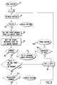
- the machine 10 When the call for service icon is activated, the machine 10 attempts to place a call to the host computer 84 via the dial/redial routine shown in the flow chart of Figure 5. Activation of the icon 104 starts a dial session at step S1.
- the machine 10 may include a hierarchy of dial routines for events of various urgency levels. Usually, a call for service will be assigned to a high priority call routine which initiates an immediate call to the host computer 84.
- step S2 the modem 48 is initialized and the dialing routine begins. Processing close to step S3 to determine if the count of calls attempted during the session equals a predetermined number N. N sets the number of redials attempted by the routine.
- step S4 the host telephone number is dialed and at step S5 the system detects the presence either of a response code or the elapse of a predetermined time.
- step S8 a determination is made if a successful connection to the host computer is made and if an affirmative determination is made, the processing goes to step S10, which comprises a data transfer session. In the data transfer session, the information from the alert criteria file and any machine physical data initiating the alert is transmitted to host computer 84. If at S8, a negative determination is made, processing flows to step S9, in which a counter is incremented by one and processing returns to S2.
- step S11 an inquiry is made if the reason for the lack of a carrier is a communication system event, if so, processing flows to step S9 and a retry is made. If the determination made in step S11 is negative, processing flows to step S12 wherein a determination is made if the attempted telephone number is invalid. If the determination in step S12 is affirmative, the dial session ends and if the determination in step S12 is negative, processing flows to step S9 and a redial is initiated. If the count at step S3 equals the predetermined count, the dial session ends and may be retried under the control of a suitable restarting routine.
- a host computer 84 having appropriate stored software for overall control of the computer 84.
- a compiler 86 is utilized to convert all incoming data into a common machine format.
- the information from the compiler 86 is provided to an addressable file 88 in which the identities of all machines served by the computer 84 may be stored.
- the file 88 may also store historical machine physical data and repair histories for each reprographic machine that is serviced by the system.
- the communication to computer 84 is a request for service
- the information from the file 88 for the machine requesting service is provided to diagnostic subsystem 90.
- the portion of the file for the reprographic machine requesting service is identified by the initial data stream received by host computer 84 during the logon procedure.
- the diagnostic subsystem 90 includes diagnostic routines that are of a higher level than those normally a part of any diagnostic system within the machine 10. On the basis of the information provided from the file 88, the subsystem 90 determines appropriate corrective measures and supplies direction to a message translation table for providing diagnostic information that can be communicated back to the machine 10 for display, for example on user interface 11, thereby enabling the operator to apply the appropriate corrective action to restart the machine. If the diagnostic subsystem 90 determines that additional machine physical data is necessary to diagnose the machine 10, a return flow of commands issues from host computer 84 through automatic call capabilities (not shown) to reprographic machine 10. The commands may place a request for additional information on the user interface 11 or obtain the required information directly from an NVM, such as hard disk 36, within the machine 10.
- NVM such as hard disk 36
- the host computer 84 also provides status information, through the communication link 50 back to the user interface 11 to advise the operator of the status of the service request.
- This information can be provided on the basis of schedule information and subroutines available in the control software of the computer 84 or can be manually provided through an input terminal 92, such as a keyboard and display unit, through an interface port 94. If the results of the diagnostic routines performed in the diagnostic subsystem 90 indicate that a repair call by a service representative is necessary to restart the reprographic machine 10, an operator at the service site 60 can provide this information, entered through input unit 92, for display at the user interface 11. Such information can include the name of the service representative assigned and the estimated time of arrival.
- the status information may be stored in the file 88 and either provided automatically to machine 10 or upon request from machine 10.
- the data stream sent by host computer 84 to machine 10 can include an appropriate identifier bit for identifying the data stream as status information.
- the status information is directed by the processor in UIM core 18 to video engine 40, to display status information in the status field 106 of the pull down menu shown in Figure 4.
- the communications switch 82 also includes a call for status request, which is preferably implemented through menu 100 displayed on UI 11.
- the call is initiated by the operator on menu 100 by actuation of the call for service icon 105, through touchscreen 12 or by use of a mouse. Basically the same procedure described above with respect to the call for service is followed with respect to the call for status.
- the initial stream includes a unique identifier for indicating that the call is for status.
- the status call is identified as such and communicated to host computer 84, including the necessary information from hard disk 36 for identifying the requesting machine.
- information regarding repair status for each machine 10 is stored in computer 84, preferably in file 88.
- the status information is entered and updated in file 88 through input terminal 92 by the host computer operator.
- the host computer 84 directs the status information back to machine 10, through communications system 50, for display on the UI 11.
- an appropriate message can be supplied to the file 88, either from UI of reprographic machine 10 or from terminal 92 to remove the service call status information from file 88.
- the foregoing system provides for the quick and accurate initiation of a service call automatically, without the need for oral communication. Thus, any errors that could result from such oral communication are substantially eliminated. Further, status information is available and automatically provided at the faulted machine without the need for oral communication with personnel at the machine site. This provides improved customer satisfaction and can contribute to lower service costs.
Abstract
Description
- This invention relates to reprographic machines. It has particular applicability to service call systems for reprographic machines.
- Recently, systems for monitoring the operation of a plurality of reprographic machines from a remote source by use of a powerful host computer having advanced, high level diagnostic capabilities have been installed. These systems have the capability to interact remotely with the machines being monitored to receive automatically initiated or user initiated requests for diagnosis and to interact with the requesting machine to receive stored data to enable higher level diagnostic analysis. Such systems are shown in U.S. Patent Nos. 5,038,319 and 5,057,866. These systems employ Remote Interactive Communications (RIC) to enable transfer of selected machine operating data (referred to as machine physical data) to the remote site at which the host computer is located, through a suitable communication channel. The machine physical data may be transmitted from a monitored document system to the remote site automatically at predetermined times and/or in response to a specific request from the host computer.
- In a typical RIC system, the host computer is linked via a public switched telephone system or a combination of public and dedicated systems to local reprographic machines via modems. The host computer may include a compiler to allow communication with a plurality of different types of machines and an expert diagnostic system that performs higher level analysis of the machine physical data than is available from the diagnostic system in the machine. After analysis, the expert system can provide an instruction message which can be utilized by the machine operator at the site of the document system to overcome a fault. Alternatively, if the expert system determines that more serious repair is necessary or a preventive repair is desirable, a message is sent to a local field work office giving the identity of the machine and a general indication of the type of service action required.
- A call for service is initiated by an operator at the machine location and is transmitted orally by telephone from the local machine operator to an operator at the host computer or at a local field work support system. This system is disadvantageous from the standpoint that the communication between the local machine operator and the remote operator is oral, the local operator commonly has only limited information about the technical aspects of the machine requiring repair and the local operator normally has little time to spend in communicating the information. The result is that the remote operator receives only limited or erroneous information relating to the identity of the machine requiring service and only a brief description of the problem requiring a repair action. If the faulted machine is erroneously identified in the oral communication between the local and remote operators, the remedial information necessary to effect a repair may be misdirected or may be inappropriate to the faulted machine, thereby causing delay in returning the machine to service and adding expense to the repair procedure. Further, in many instances, the local operator has no indication of the status of the repair request or an indication of when repair procedures will be made.
- This invention provides for improved communication between a faulted machine and a central diagnostic system or local field service facility. A user interface at the faulted machine is used to establish communication with a remote diagnostic or service facility, automatically transmit machine identity and physical data, with or without additional operator-supplied information, and to accept and display status messages, without the need for oral communication.
- By way of example only, an embodiment of the invention will be described with reference to the accompanying drawings, in which:
- Figure 1 shows a typical reprographic machine having a user interface suitable for use with a system in accordance with the present invention;
- Figure 2 is a schematic diagram of reprographic equipment having a user interface for communicating with a remote diagnostic or service facility;
- Figure 3 is a schematic illustration of the remote diagnostic or service site depicted as
element 60 in Figure 2; - Figure 4 illustrates a typical pull down menu for enabling a call for service; and
- Figure 5 is a flow chart of a communication routine.
- Referring to Figure 1, there is shown an
electrophotographic reproduction machine 10 composed of a plurality of programmable components and subsystems which cooperate to carry out copying or printing jobs programmed through atouch dialog screen 12 of a user interface (UI) 11. Internal operating systems of themachine 10 are disclosed in U.S. Patent Nos. 5,038,319 and 5,057,886 and no further detailed description thereof is necessary. - Referring to Figure 2, operation of the various components of
machine 10 is regulated by a control system which uses operating software stored in memory in thesystem controller 16 to operate the various machine components in an integrated fashion to produce copies and prints. The control system includes a plurality of printed wiring boards (PWBs), there being a user interfacemodule core PWB 18, a markingimaging core PWB 20, an inputstation core PWB 22, a paperhandling core PWB 24 and an outputstation core PWB 26, together with various input/output (I/O)PWBs 28. A shared line (SL) 30 couples thecore PWBs data node core 32, whilelocal buses 34 serve to couple the I/O PWBs to the respective cores and to stepper and servo PWBs. Programming and operating control overmachine 10 is accomplished throughtouch dialogue screen 12 ofUI 11. The operating software includes application software for implementing and coordinating operation of the machine components. -
Floppy disk port 58 provides program loading access to UIMcore PWB 18 for the purpose of entering changes to the operating software, loading specific programs, such as diagnostic programs, and retrieving stored data, such as machine history data and fault data, etc. using floppy disks.Hard disk 36 is utilized as a non-volatile memory (NVM) to store programs, machine physical data, and specific machine identity information. - UIM
core PWB 18 communicates withvideo engine 40 for driving a suitablevisual display 42, such as a CRT or flat screen of theuser interface 11. The UIMcore 18 also has connected thereto a control panel I/O processor 44 and a generic accessories interface I/O processor 46. - A two-way flow of information from the UI system manager of
core 18 is provided through the generic accessories interface input/output processor 46, which includes remote access control software and accessories control software. Information from and to the genericaccessories interface processor 46 is controlled by modem control software in themodem 48. That information is transferred via a public switchedtelephone network 50, dedicated transmission network, or other data transmission network to and from aremote service site 60. - Information in the form of signals to or from the electromechanical devices on the servo PWBs and stepper PWBs is transferred to and from the digital I/
O PWBs 28. Information from and control information to thePWBs 28 is centralized through the subsystem cores, such ascores - The information from the subsystem cores flows to and from the UIM
core 18, which embodies software control systems including a user interface system manager and a user interface diagnostic manager. The UI system manager includes a UI display manager subsystem for controlling the display of messages on thedisplay 42. A data manager subsystem provides data management to the UI system manager. The UIMcore 18 includes analert criteria file 80, preferably implemented in software, and acommunication switch 82, also implemented in software. - The alert criteria file stores in non-volatile memory, such as
hard disk 36, a plurality of alert criteria that are or can be indicative of a machine malfunction. Thealert criteria file 80 receives inputs of machine physical data from sensors in the various subsystems ofmachine 10. This data is handled through therespective system cores alert criteria file 80 through thesystem bus 30. When the alert criteria file identifies an alert condition, thefile 80 provides a command to the UIM core management software to display the appropriate system alert on theinterface 11, thereby providing a visual message or alarm to the operator. Various alert criteria can be stored onhard disk 36 and no further description of such criteria is necessary, as such criteria are generally known. When an alert message is displayed onUI 11, the operator has an option to request further diagnosis or service through thetouchscreen 12 of theuser interface 11. For this purpose, an appropriate pull down menu, such as shown in Figure 4, may be used for activatingsoftware communications switch 82 and for providing input of any additional information that the operator finds appropriate to send with a call for service. When theswitch 82 is actuated through thetouchscreen 12, machine identity data is directed throughswitch 82 to the generic accessories interface input/output processor 46 for communication via themodem 48 to the remote diagnostic orrepair site 60. The message that is sent throughswitch 82 comprises information necessary to identify the machine by model, serial number and location. - To enable the call for service feature, the capability is activated by setting a flag in memory that is in a generic protocol in the UIM core, which protocol provides access to NVM 36 through the
touchscreen 12 via the pull downmenu 100 shown in Figure 4. Display management systems for pull-down menus are known and no further detailed explanation of them is necessary here. It will be understood that during initialization, other information to enable RIC, such as modem parameters, machine model identity, machine serial number, and host computer telephone number have been entered inNVM 36. This information is handled as an initial data string that is provided to hostcomputer 86 when initiating a service call. - As shown in Figure 4, the pull down menu also can include a fault description capability enabling the operator to enter common faults by code number or by written description in the
fault description screen 102. Such fault description information also can be included in the initial data string sent to hostcomputer 84. To initiate a call for service, the operator may engage thetouchscreen 12 by hand at the location of the call forservice icon 104 or select the icon with a mouse. - When the call for service icon is activated, the
machine 10 attempts to place a call to thehost computer 84 via the dial/redial routine shown in the flow chart of Figure 5. Activation of theicon 104 starts a dial session at step S1. Themachine 10 may include a hierarchy of dial routines for events of various urgency levels. Usually, a call for service will be assigned to a high priority call routine which initiates an immediate call to thehost computer 84. - At step S2, the
modem 48 is initialized and the dialing routine begins. Processing close to step S3 to determine if the count of calls attempted during the session equals a predetermined number N. N sets the number of redials attempted by the routine. At step S4 the host telephone number is dialed and at step S5 the system detects the presence either of a response code or the elapse of a predetermined time. - At S6 a determination is made if a carrier line is detected. If a carrier line is detected, the processing goes to a logon procedure of a known type for logging on to
host computer 84 in step S7. During the logon procedure the initial data string is transmitted from the NVM to the host computer and the call is identified by at least one bit of the data stream as a call for service. In step S8 a determination is made if a successful connection to the host computer is made and if an affirmative determination is made, the processing goes to step S10, which comprises a data transfer session. In the data transfer session, the information from the alert criteria file and any machine physical data initiating the alert is transmitted tohost computer 84. If at S8, a negative determination is made, processing flows to step S9, in which a counter is incremented by one and processing returns to S2. - If a negative determination is made in step S6, in step S11, an inquiry is made if the reason for the lack of a carrier is a communication system event, if so, processing flows to step S9 and a retry is made. If the determination made in step S11 is negative, processing flows to step S12 wherein a determination is made if the attempted telephone number is invalid. If the determination in step S12 is affirmative, the dial session ends and if the determination in step S12 is negative, processing flows to step S9 and a redial is initiated. If the count at step S3 equals the predetermined count, the dial session ends and may be retried under the control of a suitable restarting routine.
- Referring to Figure 3, at a remote
diagnostic site 60 there is typically ahost computer 84 having appropriate stored software for overall control of thecomputer 84. In order to enable thecomputer 84 to communicate with a plurality of different machine types, acompiler 86 is utilized to convert all incoming data into a common machine format. The information from thecompiler 86 is provided to anaddressable file 88 in which the identities of all machines served by thecomputer 84 may be stored. Thefile 88 may also store historical machine physical data and repair histories for each reprographic machine that is serviced by the system. In the event the communication tocomputer 84 is a request for service, the information from thefile 88 for the machine requesting service is provided todiagnostic subsystem 90. The portion of the file for the reprographic machine requesting service is identified by the initial data stream received byhost computer 84 during the logon procedure. Thediagnostic subsystem 90 includes diagnostic routines that are of a higher level than those normally a part of any diagnostic system within themachine 10. On the basis of the information provided from thefile 88, thesubsystem 90 determines appropriate corrective measures and supplies direction to a message translation table for providing diagnostic information that can be communicated back to themachine 10 for display, for example onuser interface 11, thereby enabling the operator to apply the appropriate corrective action to restart the machine. If thediagnostic subsystem 90 determines that additional machine physical data is necessary to diagnose themachine 10, a return flow of commands issues fromhost computer 84 through automatic call capabilities (not shown) toreprographic machine 10. The commands may place a request for additional information on theuser interface 11 or obtain the required information directly from an NVM, such ashard disk 36, within themachine 10. - The
host computer 84 also provides status information, through thecommunication link 50 back to theuser interface 11 to advise the operator of the status of the service request. This information can be provided on the basis of schedule information and subroutines available in the control software of thecomputer 84 or can be manually provided through aninput terminal 92, such as a keyboard and display unit, through aninterface port 94. If the results of the diagnostic routines performed in thediagnostic subsystem 90 indicate that a repair call by a service representative is necessary to restart thereprographic machine 10, an operator at theservice site 60 can provide this information, entered throughinput unit 92, for display at theuser interface 11. Such information can include the name of the service representative assigned and the estimated time of arrival. The status information may be stored in thefile 88 and either provided automatically tomachine 10 or upon request frommachine 10. The data stream sent byhost computer 84 tomachine 10 can include an appropriate identifier bit for identifying the data stream as status information. The status information is directed by the processor inUIM core 18 tovideo engine 40, to display status information in thestatus field 106 of the pull down menu shown in Figure 4. - The communications switch 82 also includes a call for status request, which is preferably implemented through
menu 100 displayed onUI 11. The call is initiated by the operator onmenu 100 by actuation of the call forservice icon 105, throughtouchscreen 12 or by use of a mouse. Basically the same procedure described above with respect to the call for service is followed with respect to the call for status. The initial stream includes a unique identifier for indicating that the call is for status. The status call is identified as such and communicated tohost computer 84, including the necessary information fromhard disk 36 for identifying the requesting machine. As described above, information regarding repair status for eachmachine 10 is stored incomputer 84, preferably infile 88. The status information is entered and updated infile 88 throughinput terminal 92 by the host computer operator. When a call for status is received, thehost computer 84 directs the status information back tomachine 10, throughcommunications system 50, for display on theUI 11. When service has been completed, an appropriate message can be supplied to thefile 88, either from UI ofreprographic machine 10 or from terminal 92 to remove the service call status information fromfile 88. - The foregoing system provides for the quick and accurate initiation of a service call automatically, without the need for oral communication. Thus, any errors that could result from such oral communication are substantially eliminated. Further, status information is available and automatically provided at the faulted machine without the need for oral communication with personnel at the machine site. This provides improved customer satisfaction and can contribute to lower service costs.
Claims (6)
- A service call system for a reprographic machine comprising:
first storing means for storing identity information relating to identification of the reprographic machine;
second storing means for storing machine status information relating to the reprographic machine;
a user-activated means for initiating a communication to a remote facility; and
means responsive to actuation of the user- activated means for causing automatic transmission of the identity information and at least some of the machine status information to the remote status information facility. - A system as claimed in claim 1, wherein the machine status information comprises machine physical data.
- A system as claimed in claim 1 or claim 2, wherein the second storing means comprises a non-volatile memory located in the reprographic machine.
- A system as claimed in any one of the preceding claims, further comprising:
an input means for providing information to be transmitted to the remote service facility; and
means for transmitting information provided by the input means to the remote facility when the user- activated means is activated. - A system as claimed in any one of the preceding claims, further comprising:
a message sending device at the remote facility;
a display at the location of the reprographic machine; and
means for causing a message from the remote facility to be displayed on the display. - A system as claimed in claim 5, wherein the user- activated means and the display means comprise a touchscreen user interface.
Applications Claiming Priority (2)
| Application Number | Priority Date | Filing Date | Title |
|---|---|---|---|
| US979033 | 1992-11-20 | ||
| US07/979,033 US5325156A (en) | 1992-11-20 | 1992-11-20 | Service call initiation and feedback interface for a reprographic machine |
Publications (3)
| Publication Number | Publication Date |
|---|---|
| EP0599523A2 true EP0599523A2 (en) | 1994-06-01 |
| EP0599523A3 EP0599523A3 (en) | 1995-09-27 |
| EP0599523B1 EP0599523B1 (en) | 1996-12-04 |
Family
ID=25526626
Family Applications (1)
| Application Number | Title | Priority Date | Filing Date |
|---|---|---|---|
| EP93309066A Expired - Lifetime EP0599523B1 (en) | 1992-11-20 | 1993-11-12 | Service call initiation and feedback interface |
Country Status (4)
| Country | Link |
|---|---|
| US (1) | US5325156A (en) |
| EP (1) | EP0599523B1 (en) |
| JP (1) | JPH06217028A (en) |
| DE (1) | DE69306368T2 (en) |
Cited By (7)
| Publication number | Priority date | Publication date | Assignee | Title |
|---|---|---|---|---|
| EP0843230A2 (en) * | 1996-11-15 | 1998-05-20 | Canon Information Systems, Inc. | Remote maintenance and servicing of a network peripheral device over the world wide web |
| EP0843229A2 (en) * | 1996-11-15 | 1998-05-20 | Canon Information Systems, Inc. | Automatic service requests over the world wide web |
| NL1009817C2 (en) * | 1998-08-07 | 2000-02-08 | Oce Tech Bv | Manipulation of energy savings with imaging devices in a network system. |
| WO2002077718A1 (en) * | 2001-03-21 | 2002-10-03 | Toshiba Tec Germany Imaging Systems Gmbh | Method and system for service management or/and for service support or/and for the generation of service reports |
| CZ303371B6 (en) * | 2000-11-15 | 2012-08-22 | Heidelberger Druckmaschinen Ag | Method for transmitting operational data of a printing machine |
| WO2016057465A1 (en) * | 2014-10-07 | 2016-04-14 | Videojet Technologies Inc. | System and method for remotely servicing an industrial printer |
| EP3336784A1 (en) * | 2016-12-13 | 2018-06-20 | Ricoh Company Ltd. | Electronic device, information distribution system, information processing method, and carrier means |
Families Citing this family (54)
| Publication number | Priority date | Publication date | Assignee | Title |
|---|---|---|---|---|
| US5819110A (en) * | 1995-06-05 | 1998-10-06 | Ricoh Company, Ltd. | System for determining whether connection or connectionless modes of communication should be used to transmit information between devices in accordance with priorities of events |
| US5818603A (en) * | 1996-03-29 | 1998-10-06 | Ricoh Company, Ltd. | Method and system for controlling and communicating with machines using multiple communication formats |
| JP3121002B2 (en) * | 1990-07-06 | 2000-12-25 | 株式会社リコー | Printer systems, printers and external devices |
| JP3227750B2 (en) * | 1991-12-10 | 2001-11-12 | ミノルタ株式会社 | Copier |
| JP3660363B2 (en) * | 1992-05-28 | 2005-06-15 | 株式会社リコー | Image forming apparatus management system and image forming apparatus |
| JP3347781B2 (en) * | 1992-12-11 | 2002-11-20 | 株式会社リコー | Image forming device management system |
| JPH07162825A (en) * | 1993-12-02 | 1995-06-23 | Canon Inc | Remote maintaining device for video conference system |
| US5414494A (en) * | 1993-12-06 | 1995-05-09 | Xerox Corporation | Automatic call to selected remote operators in response to predetermined machine conditions |
| US5412452A (en) * | 1993-12-20 | 1995-05-02 | Xerox Corporation | Apparatus and method for controlling diagnostic routines concurrently in a printing system |
| JPH07181842A (en) * | 1993-12-24 | 1995-07-21 | Canon Inc | Management system for copying device |
| US5638427A (en) * | 1994-07-01 | 1997-06-10 | Xerox Corporation | Operator-controlled interactive communication device |
| JP3180940B2 (en) * | 1994-11-28 | 2001-07-03 | 京セラミタ株式会社 | Image forming device maintenance management device |
| JP3442174B2 (en) * | 1995-01-19 | 2003-09-02 | 株式会社リコー | Image forming device service system |
| US5852746A (en) * | 1995-06-26 | 1998-12-22 | Canon Kabushiki Kaisha | System for transmitting a message using status button to system administrator by using a signal comprising predetermined number of changes effected over a period |
| US5678002A (en) * | 1995-07-18 | 1997-10-14 | Microsoft Corporation | System and method for providing automated customer support |
| US5694528A (en) * | 1995-11-22 | 1997-12-02 | Xerox Corporation | Apparatus and method for diagnosing printing machine operation with facsimile transmitted dialog screens |
| US5737739A (en) * | 1995-12-19 | 1998-04-07 | Xerox Corporation | System that accesses a knowledge base by markup language tags |
| CN1166633A (en) * | 1995-12-28 | 1997-12-03 | 株式会社东芝 | Imaging device |
| JP3566020B2 (en) * | 1997-03-07 | 2004-09-15 | 株式会社リコー | Image forming device management system |
| JP3566037B2 (en) * | 1997-07-25 | 2004-09-15 | 株式会社リコー | Image forming device management system |
| US6167533A (en) * | 1998-06-25 | 2000-12-26 | Hewlett-Packard Company | Active dashboard extensible framework |
| US6687874B2 (en) | 1998-10-05 | 2004-02-03 | Nexpress Solutions Llc | System for generating and maintaining field service publications |
| US6370231B1 (en) * | 1998-11-24 | 2002-04-09 | Bellsouth Intellectual Property Corporation | Method and system for calculating the estimated time of arrival of a service technician |
| US7127499B1 (en) * | 1998-11-25 | 2006-10-24 | General Electric Company | Medical diagnostic system service method and apparatus |
| US6701095B1 (en) * | 1999-01-08 | 2004-03-02 | Ricoh Company, Ltd. | Office information system having a device which provides an operational message of the system when a specific event occurs |
| US6665085B1 (en) | 1999-05-25 | 2003-12-16 | Xerox Corporation | Simultaneous voice and data communication for diagnostic procedures in a printing or copying machine |
| US6246325B1 (en) * | 1999-11-18 | 2001-06-12 | Agere Systems Guardian Corp. | Distributed communications system for reducing equipment down-time |
| US7117239B1 (en) | 2000-07-28 | 2006-10-03 | Axeda Corporation | Reporting the state of an apparatus to a remote computer |
| US8108543B2 (en) | 2000-09-22 | 2012-01-31 | Axeda Corporation | Retrieving data from a server |
| US7185014B1 (en) | 2000-09-22 | 2007-02-27 | Axeda Corporation | Retrieving data from a server |
| US7149792B1 (en) | 2000-11-20 | 2006-12-12 | Axeda Corporation | Device registration mechanism |
| US20040260790A1 (en) * | 2000-12-21 | 2004-12-23 | Ge Medical System Global Technology Company, Llc | Method and apparatus for remote or collaborative control of an imaging system |
| DE10102051A1 (en) * | 2001-01-17 | 2002-08-29 | Claas Selbstfahr Erntemasch | Procedure for planning a repair of mobile work machines |
| JP2002244724A (en) * | 2001-02-20 | 2002-08-30 | Honda Motor Co Ltd | Remote monitoring device for machine and management method therefor |
| US20020128875A1 (en) * | 2001-03-07 | 2002-09-12 | Travis Parry | System and method for providing customer support |
| US6975913B2 (en) | 2001-07-13 | 2005-12-13 | Siemens Aktiengesellschaft | Database system and method for industrial automation services |
| US7603289B2 (en) * | 2001-07-13 | 2009-10-13 | Siemens Aktiengesellschaft | System and method for electronic delivery of content for industrial automation systems |
| US6625403B2 (en) | 2001-11-05 | 2003-09-23 | Nexpress Solutions Llc | Personalization of operator replaceable component life prediction based on replaceable component life history |
| US6718285B2 (en) | 2001-11-05 | 2004-04-06 | Nexpress Solutions Llc | Operator replaceable component life tracking system |
| US7254601B2 (en) | 2001-12-20 | 2007-08-07 | Questra Corporation | Method and apparatus for managing intelligent assets in a distributed environment |
| US20030135431A1 (en) * | 2001-12-20 | 2003-07-17 | Nexpress Solutions Llc | Linking ORC life tracking/usage with inventory management |
| US7178149B2 (en) | 2002-04-17 | 2007-02-13 | Axeda Corporation | XML scripting of soap commands |
| US8024236B2 (en) * | 2002-11-22 | 2011-09-20 | Eastman Kodak Company | Method and apparatus for reducing supply orders in inventory management |
| US7966418B2 (en) | 2003-02-21 | 2011-06-21 | Axeda Corporation | Establishing a virtual tunnel between two computer programs |
| DE102005016784B4 (en) * | 2004-05-04 | 2013-07-25 | Heidelberger Druckmaschinen Ag | Remote diagnostics system for printing machines |
| JP5095922B2 (en) * | 2004-05-04 | 2012-12-12 | ハイデルベルガー ドルツクマシーネン アクチエンゲゼルシヤフト | Remote diagnosis system for printing press |
| US7715037B2 (en) * | 2005-03-01 | 2010-05-11 | Xerox Corporation | Bi-directional remote visualization for supporting collaborative machine troubleshooting |
| DE102006006438A1 (en) * | 2006-02-13 | 2007-08-16 | Heidelberger Druckmaschinen Ag | Method for the secure transmission of operating data |
| US8370479B2 (en) | 2006-10-03 | 2013-02-05 | Axeda Acquisition Corporation | System and method for dynamically grouping devices based on present device conditions |
| US8065397B2 (en) | 2006-12-26 | 2011-11-22 | Axeda Acquisition Corporation | Managing configurations of distributed devices |
| US8478861B2 (en) | 2007-07-06 | 2013-07-02 | Axeda Acquisition Corp. | Managing distributed devices with limited connectivity |
| KR101571538B1 (en) * | 2008-11-28 | 2015-11-24 | 삼성전자주식회사 | Calling method in a touch pannel type portable terminal |
| US8621362B2 (en) | 2011-01-21 | 2013-12-31 | Xerox Corporation | Mobile screen methods and systems for collaborative troubleshooting of a device |
| CN111228793B (en) * | 2020-01-21 | 2021-11-19 | 腾讯科技(深圳)有限公司 | Interactive interface display method and device, storage medium and electronic device |
Citations (2)
| Publication number | Priority date | Publication date | Assignee | Title |
|---|---|---|---|---|
| FR2664403A1 (en) * | 1990-07-06 | 1992-01-10 | Ricoh Kk | Apparatus making it possible to control and bring about communication between office-automation devices |
| US5084875A (en) * | 1989-12-13 | 1992-01-28 | Joseph Weinberger | System for automatically monitoring copiers from a remote location |
Family Cites Families (11)
| Publication number | Priority date | Publication date | Assignee | Title |
|---|---|---|---|---|
| US4390953A (en) * | 1980-11-10 | 1983-06-28 | Kearney & Trecker Corporation | Unmanned diagnostic communications system for computer controlled machine tools |
| US4703325A (en) * | 1984-10-22 | 1987-10-27 | Carrier Corp. | Remote subsystem |
| FR2591000B1 (en) * | 1985-11-29 | 1988-09-23 | Spie Batignolles | ASSISTANCE DEVICE FOR THE MAINTENANCE OF AN ELECTROMECHANICAL INSTALLATION WHICH INCLUDES AUTOMATIC CONTROL AND CONTROL MEANS |
| US4996703A (en) * | 1986-04-21 | 1991-02-26 | Gray William F | Remote supervisory monitoring and control apparatus connected to monitored equipment |
| US4718079A (en) * | 1986-06-30 | 1988-01-05 | Giuseppe Rabito | Remote unit monitoring system |
| US4823290A (en) * | 1987-07-21 | 1989-04-18 | Honeywell Bull Inc. | Method and apparatus for monitoring the operating environment of a computer system |
| US5010568A (en) * | 1989-04-04 | 1991-04-23 | Sparton Corporation | Remote meter reading method and apparatus |
| US5241402A (en) * | 1989-12-04 | 1993-08-31 | Xerox Corporation | Concurrent modem control in a reprographic machine |
| US5214772A (en) * | 1989-12-13 | 1993-05-25 | Joseph Weinberger | System for automatically monitoring copiers from a remote location |
| US5216461A (en) * | 1990-07-31 | 1993-06-01 | Minolta Camera Kabushiki Kaisha | Control system for copying machine with improved communication function to centralized control unit |
| US5220380A (en) * | 1990-08-10 | 1993-06-15 | Minolta Camera Kabushiki Kaisha | Control system for copying machines with improved communication function for centralized control unit |
-
1992
- 1992-11-20 US US07/979,033 patent/US5325156A/en not_active Expired - Lifetime
-
1993
- 1993-06-25 JP JP5155830A patent/JPH06217028A/en active Pending
- 1993-11-12 DE DE69306368T patent/DE69306368T2/en not_active Expired - Lifetime
- 1993-11-12 EP EP93309066A patent/EP0599523B1/en not_active Expired - Lifetime
Patent Citations (2)
| Publication number | Priority date | Publication date | Assignee | Title |
|---|---|---|---|---|
| US5084875A (en) * | 1989-12-13 | 1992-01-28 | Joseph Weinberger | System for automatically monitoring copiers from a remote location |
| FR2664403A1 (en) * | 1990-07-06 | 1992-01-10 | Ricoh Kk | Apparatus making it possible to control and bring about communication between office-automation devices |
Cited By (19)
| Publication number | Priority date | Publication date | Assignee | Title |
|---|---|---|---|---|
| US6473788B1 (en) | 1996-11-15 | 2002-10-29 | Canon Kabushiki Kaisha | Remote maintenance and servicing of a network peripheral device over the world wide web |
| EP0843230A2 (en) * | 1996-11-15 | 1998-05-20 | Canon Information Systems, Inc. | Remote maintenance and servicing of a network peripheral device over the world wide web |
| EP0843229A3 (en) * | 1996-11-15 | 1998-07-08 | Canon Information Systems, Inc. | Automatic service requests over the world wide web |
| US6003078A (en) * | 1996-11-15 | 1999-12-14 | Canon Information Systems, Inc. | Automatic service requests over the world wide web |
| EP0843230A3 (en) * | 1996-11-15 | 1998-06-03 | Canon Information Systems, Inc. | Remote maintenance and servicing of a network peripheral device over the world wide web |
| EP0843229A2 (en) * | 1996-11-15 | 1998-05-20 | Canon Information Systems, Inc. | Automatic service requests over the world wide web |
| US7454476B2 (en) | 1996-11-15 | 2008-11-18 | Canon Kabushiki Kaisha | Remote maintenance and servicing of a network peripheral device over the world wide web |
| EP1591840A1 (en) * | 1996-11-15 | 2005-11-02 | Canon Kabushiki Kaisha | Automatic service requests over the world wide web |
| US6813037B1 (en) | 1998-08-07 | 2004-11-02 | Océ-Technologies B.V. | Manipulation of energy conservation in image forming devices in a network system |
| NL1009817C2 (en) * | 1998-08-07 | 2000-02-08 | Oce Tech Bv | Manipulation of energy savings with imaging devices in a network system. |
| EP0978767A1 (en) * | 1998-08-07 | 2000-02-09 | Océ-Technologies B.V. | Manipulation of energy conservation in image forming devices in a network system |
| CZ303371B6 (en) * | 2000-11-15 | 2012-08-22 | Heidelberger Druckmaschinen Ag | Method for transmitting operational data of a printing machine |
| WO2002077718A1 (en) * | 2001-03-21 | 2002-10-03 | Toshiba Tec Germany Imaging Systems Gmbh | Method and system for service management or/and for service support or/and for the generation of service reports |
| EP3797997A1 (en) * | 2014-10-07 | 2021-03-31 | Videojet Technologies Inc. | System and method for remotely servicing an industrial printer |
| US9524132B2 (en) | 2014-10-07 | 2016-12-20 | Videojet Technologies, Inc. | System and method for remotely servicing an industrial printer |
| CN107000435A (en) * | 2014-10-07 | 2017-08-01 | 录象射流技术公司 | System and method for remote service industrial printer |
| WO2016057465A1 (en) * | 2014-10-07 | 2016-04-14 | Videojet Technologies Inc. | System and method for remotely servicing an industrial printer |
| EP3336784A1 (en) * | 2016-12-13 | 2018-06-20 | Ricoh Company Ltd. | Electronic device, information distribution system, information processing method, and carrier means |
| US10291791B2 (en) | 2016-12-13 | 2019-05-14 | Ricoh Company, Ltd. | Electronic device, information distribution system, information processing method, and recording medium |
Also Published As
| Publication number | Publication date |
|---|---|
| DE69306368T2 (en) | 1997-06-12 |
| DE69306368D1 (en) | 1997-01-16 |
| US5325156A (en) | 1994-06-28 |
| EP0599523A3 (en) | 1995-09-27 |
| JPH06217028A (en) | 1994-08-05 |
| EP0599523B1 (en) | 1996-12-04 |
Similar Documents
| Publication | Publication Date | Title |
|---|---|---|
| EP0599523B1 (en) | Service call initiation and feedback interface | |
| US5636008A (en) | Remote/shared system user interface | |
| JP3576209B2 (en) | Remote diagnosis method for copy quality defects | |
| JP3121002B2 (en) | Printer systems, printers and external devices | |
| US7385928B2 (en) | Image forming device management system and method | |
| US6415392B1 (en) | Remote diagnosis system and method | |
| US6665085B1 (en) | Simultaneous voice and data communication for diagnostic procedures in a printing or copying machine | |
| US20020183978A1 (en) | Remote maintenance and diagnosis of office or domestic appliances | |
| JPH07192187A (en) | Remote monitoring system | |
| JPH03293371A (en) | Controller for copying machine | |
| JP2000214733A (en) | Image forming device managing system | |
| EP1227618B1 (en) | Administration system, apparatus and method and relay server | |
| JPH1146268A (en) | Image-forming device management system | |
| US4807276A (en) | Re-transmission method and apparatus in communication system using public communication lines | |
| US20040168109A1 (en) | Efficient remote management of devices by accurately removing abnormal condition reports | |
| US6173320B1 (en) | Visual feedback for installation of equipment | |
| JPH07325734A (en) | Field-service telecommunication system | |
| US6956934B2 (en) | Management system and method, and data processing apparatus | |
| EP0373278A1 (en) | Remote power on control device | |
| JP2005115716A (en) | Remote control system | |
| JPH1032944A (en) | Facility monitoring system | |
| US6434709B1 (en) | Remote diagnostic system for diagnosing devices connected to a plurality of terminals | |
| JP2567498B2 (en) | Elevator signal transmission device | |
| JP2004086033A (en) | Remote management device | |
| JP3701887B2 (en) | Image forming apparatus, image forming apparatus management system, program, and computer-readable recording medium |
Legal Events
| Date | Code | Title | Description |
|---|---|---|---|
| PUAI | Public reference made under article 153(3) epc to a published international application that has entered the european phase |
Free format text: ORIGINAL CODE: 0009012 |
|
| AK | Designated contracting states |
Kind code of ref document: A2 Designated state(s): DE FR GB |
|
| PUAL | Search report despatched |
Free format text: ORIGINAL CODE: 0009013 |
|
| AK | Designated contracting states |
Kind code of ref document: A3 Designated state(s): DE FR GB |
|
| 17P | Request for examination filed |
Effective date: 19960327 |
|
| GRAG | Despatch of communication of intention to grant |
Free format text: ORIGINAL CODE: EPIDOS AGRA |
|
| GRAH | Despatch of communication of intention to grant a patent |
Free format text: ORIGINAL CODE: EPIDOS IGRA |
|
| GRAH | Despatch of communication of intention to grant a patent |
Free format text: ORIGINAL CODE: EPIDOS IGRA |
|
| 17Q | First examination report despatched |
Effective date: 19960719 |
|
| GRAA | (expected) grant |
Free format text: ORIGINAL CODE: 0009210 |
|
| AK | Designated contracting states |
Kind code of ref document: B1 Designated state(s): DE FR GB |
|
| REF | Corresponds to: |
Ref document number: 69306368 Country of ref document: DE Date of ref document: 19970116 |
|
| ET | Fr: translation filed | ||
| PLBE | No opposition filed within time limit |
Free format text: ORIGINAL CODE: 0009261 |
|
| STAA | Information on the status of an ep patent application or granted ep patent |
Free format text: STATUS: NO OPPOSITION FILED WITHIN TIME LIMIT |
|
| 26N | No opposition filed | ||
| REG | Reference to a national code |
Ref country code: GB Ref legal event code: IF02 |
|
| REG | Reference to a national code |
Ref country code: GB Ref legal event code: 746 Effective date: 20050809 |
|
| PGFP | Annual fee paid to national office [announced via postgrant information from national office to epo] |
Ref country code: DE Payment date: 20121025 Year of fee payment: 20 |
|
| PGFP | Annual fee paid to national office [announced via postgrant information from national office to epo] |
Ref country code: GB Payment date: 20121025 Year of fee payment: 20 |
|
| PGFP | Annual fee paid to national office [announced via postgrant information from national office to epo] |
Ref country code: FR Payment date: 20130107 Year of fee payment: 20 |
|
| REG | Reference to a national code |
Ref country code: DE Ref legal event code: R071 Ref document number: 69306368 Country of ref document: DE |
|
| REG | Reference to a national code |
Ref country code: GB Ref legal event code: PE20 Expiry date: 20131111 |
|
| PG25 | Lapsed in a contracting state [announced via postgrant information from national office to epo] |
Ref country code: GB Free format text: LAPSE BECAUSE OF EXPIRATION OF PROTECTION Effective date: 20131111 Ref country code: DE Free format text: LAPSE BECAUSE OF EXPIRATION OF PROTECTION Effective date: 20131113 |