EP0602992A1 - Grating-prism combination - Google Patents
Grating-prism combination Download PDFInfo
- Publication number
- EP0602992A1 EP0602992A1 EP93310205A EP93310205A EP0602992A1 EP 0602992 A1 EP0602992 A1 EP 0602992A1 EP 93310205 A EP93310205 A EP 93310205A EP 93310205 A EP93310205 A EP 93310205A EP 0602992 A1 EP0602992 A1 EP 0602992A1
- Authority
- EP
- European Patent Office
- Prior art keywords
- grating
- prism
- optical element
- light
- dispersive optical
- Prior art date
- Legal status (The legal status is an assumption and is not a legal conclusion. Google has not performed a legal analysis and makes no representation as to the accuracy of the status listed.)
- Granted
Links
- 230000003287 optical effect Effects 0.000 claims abstract description 51
- 230000004304 visual acuity Effects 0.000 claims abstract description 32
- 230000003595 spectral effect Effects 0.000 claims description 20
- 239000000463 material Substances 0.000 claims description 10
- 238000003384 imaging method Methods 0.000 claims description 5
- 238000010521 absorption reaction Methods 0.000 claims description 3
- 238000001228 spectrum Methods 0.000 claims description 2
- 230000005855 radiation Effects 0.000 description 15
- 238000010586 diagram Methods 0.000 description 9
- 239000006185 dispersion Substances 0.000 description 6
- 230000003321 amplification Effects 0.000 description 2
- 238000003199 nucleic acid amplification method Methods 0.000 description 2
- 230000004075 alteration Effects 0.000 description 1
- 238000004458 analytical method Methods 0.000 description 1
- 150000001875 compounds Chemical class 0.000 description 1
- 230000007812 deficiency Effects 0.000 description 1
- 238000001514 detection method Methods 0.000 description 1
- 239000003814 drug Substances 0.000 description 1
- 230000005670 electromagnetic radiation Effects 0.000 description 1
- 230000007613 environmental effect Effects 0.000 description 1
- 238000004519 manufacturing process Methods 0.000 description 1
- 239000000203 mixture Substances 0.000 description 1
- 230000004048 modification Effects 0.000 description 1
- 238000012986 modification Methods 0.000 description 1
- 238000005070 sampling Methods 0.000 description 1
- 238000000926 separation method Methods 0.000 description 1
Images

Classifications
-
- G—PHYSICS
- G02—OPTICS
- G02B—OPTICAL ELEMENTS, SYSTEMS OR APPARATUS
- G02B27/00—Optical systems or apparatus not provided for by any of the groups G02B1/00 - G02B26/00, G02B30/00
- G02B27/42—Diffraction optics, i.e. systems including a diffractive element being designed for providing a diffractive effect
- G02B27/4233—Diffraction optics, i.e. systems including a diffractive element being designed for providing a diffractive effect having a diffractive element [DOE] contributing to a non-imaging application
- G02B27/4244—Diffraction optics, i.e. systems including a diffractive element being designed for providing a diffractive effect having a diffractive element [DOE] contributing to a non-imaging application in wavelength selecting devices
-
- G—PHYSICS
- G01—MEASURING; TESTING
- G01J—MEASUREMENT OF INTENSITY, VELOCITY, SPECTRAL CONTENT, POLARISATION, PHASE OR PULSE CHARACTERISTICS OF INFRARED, VISIBLE OR ULTRAVIOLET LIGHT; COLORIMETRY; RADIATION PYROMETRY
- G01J3/00—Spectrometry; Spectrophotometry; Monochromators; Measuring colours
- G01J3/12—Generating the spectrum; Monochromators
- G01J3/14—Generating the spectrum; Monochromators using refracting elements, e.g. prisms
-
- G—PHYSICS
- G02—OPTICS
- G02B—OPTICAL ELEMENTS, SYSTEMS OR APPARATUS
- G02B5/00—Optical elements other than lenses
- G02B5/04—Prisms
-
- G—PHYSICS
- G02—OPTICS
- G02B—OPTICAL ELEMENTS, SYSTEMS OR APPARATUS
- G02B5/00—Optical elements other than lenses
- G02B5/18—Diffraction gratings
- G02B5/1814—Diffraction gratings structurally combined with one or more further optical elements, e.g. lenses, mirrors, prisms or other diffraction gratings
Landscapes
- Physics & Mathematics (AREA)
- General Physics & Mathematics (AREA)
- Spectroscopy & Molecular Physics (AREA)
- Optics & Photonics (AREA)
- Spectrometry And Color Measurement (AREA)
- Diffracting Gratings Or Hologram Optical Elements (AREA)
Abstract
Description
- The present invention contains subject matter which is related to copending U.S. Patent Application entitled "Achromatic and Apochromatic prism element employing prisms and gratings" Serial No.: 07/989417, which is assigned as the same assignee as the present application.
- This invention relates to dispersive optical elements, and particularly to a dispersive optical element having characteristics of both prisms and a gratings.
- Dispersive optical elements have many important uses. Such elements disperse light by deviating the path of light passing through them by an amount that varies with wavelength. Prisms and gratings are the two most widely used dispersive optical elements. Prisms disperse light because their geometry causes light of different wavelengths passing through them to be separated and deviated by different amounts. In diffraction gratings light passing through the grating is diffracted into a series of orders caused by the interference of wavefronts emitted from each slit in the grating. One important application of dispersive optical elements is the production of spectrometers. Spectrometers have important applications in many fields such as medicine, material sciences, chemistry, environmental sciences, etc. Spectrometers use dispersive optical elements such as gratings or prisms, to permit the analysis of the spectral composition of sampled light.
- Grating spectrometers and prism spectrometers each have various advantages and disadvantages. For example, the resolving power of a prism has large variations over wide spectral bands. This is because a prism's resolving power is a function of the prism material dispersion, which various in a highly non-linear fashion with wavelengths. In most cases, the resolving power for a prism does not match the desired spectral characteristic curve regardless of the choice of materials. For example, where wide spectral coverage is desired the wide variation in the resolving power of a prism spectrometer over this wide spectral band severally limits its usefulness.
- Spectrometers utilizing gratings have other disadvantages. In a grating spectrometer the grating can typically be used over only one diffractive order since the optical efficiency in other orders will be very low. This limits the flexibility of the grating. Also, the wide separation of light for different diffractive orders may prevent their detection in a single detector thus limiting their usefulness in many applications. Further, the resolving power of a grating is independent of a wavelength. As a result, the dynamic range of the resolving power is fixed and can not be adapted to fit a desired spectrometer specification. The dynamic range of the resolving power is the variation in the resolving power with wavelength. For example, it may be desired to have a resolving power of 100 in the wavelength range of 25 to 26 microns, and a resolving power of 1000 in the wavelength range of 5 to 7 microns. In sum, in many applications (such as spectrometers), it is desirable to have a dispersive optical element with a predefined resolving power characteristic curve. It may be desired that the curve be linear, constant or some other defined curve. Whether one chooses prisms or gratings, the flexibility to achieve a desire curve is severally limited.
- Thus, it would be desirable to provide a dispersive optical element that is more flexible in its dispersive characteristics than gratings or prisms. Further, it would be desired to provide a dispersive optical element in which the spectral curve of the resolving power can be predetermined with greater specificity than is possible with either gratings or prisms. Further, it would be desirable to provide such a dispersive optical element that is simple and can be produced at relatively low cost.
- Pursuant to the present invention a dispersive optical element is provided which includes a prism and a grating disposed adjacent to one surface of the prism. Light, after passing through the prism is dispersed further by the grating. The grating may be attached to the prism as in a preferred embodiment of the present invention. Further, the grating may be adjacent to either the first or the second surface of the prism. As a result, the dispersive optical element has dispersive characteristics, such as resolving power, that can be optimized in a vary flexible manner by choice of both the grating and prism characteristics. That is, the prism parameters can be determined by the geometry and material chosen, and the grating characteristics can be specified by the number of gratings, the diffractive order and the type of grating used. As a result, the grating may be used to amplify the angular spread introduced by the prism and different diffractive orders may be used simultaneously. This results in a very flexible and improved dynamic range of the resolving power for the diffractive optical element.
- The various advantages of the present invention will become apparent to one skilled in the art by reading the following specification and by reference of the following drawings which:
- FIG. 1 is a schematic diagram of a prism spectrometer in accordance with the prior art;
- FIG. 2 is a schematic diagram of a grating spectrometer in accordance with the prior art;
- FIG. 3 is a schematic diagram of a grism spectrometer in accordance with a first embodiment of the present invention;
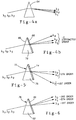
- FIG. 4A is a schematic diagram of a prism spectrometer dispersing three wavelength bands;
- FIG. 4B is a schematic diagram of a equally-diffracted grism spectrometer utilizing the minus one diffractive order of the grating in accordance with a second embodiment of the present invention;
- FIG. 5 is a schematic diagram of a partially-diffracted grism spectrometer in accordance with a third embodiment of the present invention; and
- FIG. 6 is a schematic diagram of an unequally-diffracted grism spectrometer in accordance with a fourth embodiment of the present invention.
- The present invention is a dispersive optical element utilizing both a grating and a prism. Accordingly, this dispersive optical element will be called a "grism". A grism utilizes the unique properties of both a prism and a grating. These unique properties will be discussed in more detail below. While the preferred embodiment of the present invention utilizes the prism in a spectrometer, it will be appreciated that the other uses may be employed for a grism based on the teachings of the present invention. These include aberration correction, wavefront sampling, multiple beams combining, etc.
- Referring now to FIG. 1 a schematic diagram of a
classic prism spectrometer 10 is shown.Electromagnetic radiation 12, which will be typically anywhere between infrared and ultra-violet wavelengths, enters the spectrometer through anentrance slit 14. Theradiation 12 is collimated by a set of collimatingoptics 16 and then enters aprism 18 having first 20 andsecond surfaces 22. The dispersed radiation emitted from theprism 18 then enters a set ofimaging optics 24, which focusses the radiation onto adetector 26. The dispersion of theradiation 12 by theprism 18 will cause the radiation to be angularly separated for different wavelengths on thedetector 26. The image on thedetector 26 will consist of separated chromatic slit images. - The resolving power of a
typical prism spectrometer 10 is:
where
prism 18. The index of refraction as a function of wavelength can be approximated as:
Where A₁,A₂... are constants which are characteristic of a particular prism material. By differentiating the index formula, the dispersion can be expressed as:
Therefore, as equation 3 illustrates, the dispersion characteristics of a typical prism can be highly nonlinear. As a result, the resolving power of a typical prism spectrometer will also be highly nonlinear with wavelength. Thus, the resolving power of the prism is highly nonlinear and is fixed by the choice of prism material. In sum, the resolving power of a prism is fixed by a choice of material and can not be fine tuned to particular system requirements. - A typical grating
spectrometer 28 is shown in FIG. 2. Thisgrating spectrometer 28 is a well known configuration commonly known as Czerny-Turner Mounting.Optical radiation 30 enters thespectrometer 28 through an entrance slit 32 and is reflected and collimated by acollimating optics unit 34 which serves the same function as thecollimating optic 16 in FIG. 1. Theoptical radiation 30 is then reflected onto a grating 36, which is a reflection type grating that serves a dispersive function similar to that ofprism 18 in FIG. 1. The optical radiation is then reflected by imagingoptics 38 which focusses the optical radiation onto a detector (not shown) through a exit slit 40. - The resolving power of the
grating spectrometer 28 is p x m, where small p is the diffracted order and m is the total number of grating lines in thegrating 36. This illustrates that the resolving power of the grating 36 is independent of wavelength. - To overcome the above-mentioned deficiencies of both prism and grating spectrometers, the present invention utilizes a "grism", which consists of a single dispersive optical element utilizing both a prism and a grating. FIG. 3 is a schematic diagram of a
grism spectrometer 42 in accordance with a first preferred embodiment of the present invention.Optical radiation 44 enters the spectrometer through an entrance slit 46 and is collimated byconventional collimating optics 48. The light then enters thegrism 50 where it is dispersed. Theoptical radiation 44 is then focused by animaging optics unit 52 into a spectrum on adetector 54. - In more detail, the
grism 50 comprises aprism 56 having afirst surface 58 andsecond surface 60. A grating 62 is etched onto thesecond surface 60 of the prism. It will be appreciated that while the grating 62 is etched onto thesecond surface 60 in the preferred embodiment, other variations are possible while still achieving the advantages of the present invention. For example, grating 62 may be mounted to thefirst surface 58 of the prism, or comprise a reflective grating instead of thetransmissive grating 62. In the case of reflective grating, for example, theoptical radiation 44 may pass through the prism and impinge upon the reflective grating on the second surface of the prism and then pass through the prism again in the opposite direction. In such a configuration the collimating optics could also be used as the imaging optics. Also, in other embodiments, the grating may be attached to the prism by other means, or may comprise a separate grating placed adjacent to the prism and not actually attached. Further it will be appreciated that many different kinds of gratings can be used, such as a blazed grating, binary optics, volume hologram, surface relief hologram, or an absorption grating. - It is important to note that the
optical radiation 44 undergoes dispersion in the prism and is further dispersed by thegrating 62. Therefore, the combination of a prism and a grating provides more flexibility in creating a resolving power function for meeting specific requirements for various applications. The resolving power of a "grism" is
where B is the prism base width,
grating 62. In accordance with the present invention, with judicious selection of diffractive order for each spectral band, the dynamic range of the resolving power of the grism can be greatly improved over that of a prism or a grating alone. - In selecting the grism parameters, it should be noted that there are two important parameters associated with a grating: resolving power and diffraction efficiency. The resolving power is controlled by the grating period m and the diffraction order p. The grating efficiency is controlled by the parameters related to the diffraction mechanism. For instance, the diffraction efficiency of a blazed grating is a function of the ratio of the blazed width to the grating period. On the other hand, the diffraction efficiency of the a volume hologram is a function of the modulation of the index of refraction.
- Among the variations in the
basic grism spectrometer 42 of FIG. 3 are three additional embodiments utilizing particular predetermined diffractive orders to achieve different desired spectral characteristics. These three embodiments are shown in FIGS. 4, 5, and 6 are referred to as the equally-diffracted grism, the partially-diffracted grism, and unequally-diffracted grism. In FIG. 4A-B, an equally-diffracted grism in accordance with a second preferred embodiment of the present invention is shown. FIG. 4A illustrates aconventional prism 64 in which radiation having average wavelength in three spectral bands is diffracted by theprism 64 as shown. These three spectral bands may comprise, for example, 1, 2, and 4 micrometers. Utilizing aconventional prism 64 it can be seen that the angular spread of the three spectral bands is relatively small. In FIG. 4B agrism 66 in accordance with the present invention is shown. Thegrism 66 includes a grating 68 andprism 70. The same three spectral bands as in FIG. 4A are now diffracted by thegrism 66 using the same diffractive order. In particular, each of the three bands are diffracted into theminus 1 order. That is, the pi's in equation 4 are all the same. As a result of the combination of the prism and grating, it can be seen that the grism 65 has amplified the angular spread of the three bands as compared to the prism alone. This amplification has many advantages which may be used in a number of ways depending upon the application. For example, this amplification of angular spread may be used to increase the resolution of a spectrometer. - Referring now to FIG. 5, a
grism 72 in accordance with a third embodiment of the present invention is shown in the partially-diffracted grism arrangement. Here, thegrism 72 which includes grating 74 andprism 76 is similar to that ofgrism 66 in FIG. 4B except that the zeroth diffractive order is used. Here, all three spectral bands are first dispersed by the prism. Band three is then further diffracted by the grating 74 using the first order. Bands one and two are outside of the grating diffraction envelope. Thus, very little radiation in bands one and two is diffracted into other orders except the zero order. As a consequence, there is no further angular spread for bands one and two. - FIG. 6 shows a third variation in which a
grism 78 having a grating 80 and aprism 82 results in an "unequal-diffracted grism, wherebands 1, 2 and 3 are diffracted by the grating each using different diffractive orders. This arrangement not only has very good resolving power due to the use of the higher diffraction orders, but also the size of the resulting spectrometer can also be made very compact. It will be appreciated that the selection of each of the three types of grisms shown in FIGS. 4B, 5, and 6 are designed using equation 4. That is, by selection of the parameters such as the number of grating lines, and diffractive order for each particular spectral band. It will also be appreciated that if the grating is a blazed grating, then the desired configuration is achieved by manipulating the parameter of the grating equation to achieve the blazed condition for the desired bands. It should also be noted that to further enhance the dynamic range of a grism spectrometer, the prism used may be replaced by a compound prism consisting of several prisms with different types of materials and proper prism angles. Thus, by judiciously selecting the constant A of these prisms, the desired performance can be achieved as defined by equation 4 above. - From the foregoing it can be seen that the present invention permits the distribution of resolving power between the prism and the grating to yield a grism in which the dynamic range of the resolving power is greatly improved. Further, the selection of the proper diffraction orders can result in a further enhancement of the resolving power by adjusting the diffraction efficiency function. Additional adjustments of the efficiency function of the grism can be achieved through the use of various types of gratings including blazed gratings, binary gratings, volume phase gratings, surface relief gratings, or absorption gratings.
- Those skilled in the art can appreciate that other advantages can be obtained from the use of this invention and that modification may be made without departing from the true spirit of the invention after studying the specification, drawings and following claims.
Claims (15)
- A dispersive optical element comprising:
a prism; and
grating means adjacent to one surface of the prism, wherein light passing through the optical element is dispersed by both the prism and the grating. - The dispersive optical element of Claim 1 wherein the prism has a first and second surface and the grating is a transmissive grating.
- The dispersive optical element of Claim 2 wherein the grating is attached to said first surface.
- The dispersive optical element of Claim 1 wherein the prism has a first and second surface and the grating is a reflective grating attached to the second surface.
- The dispersive optical element of Claim 1 wherein the grating is a blazed grating.
- The dispersive optical element of Claim 1 wherein the grating is a binary optical grating.
- The dispersive optical element of Claim 1 wherein the grating is a volume hologram.
- The dispersive optical element of Claim 1 wherein the grating is a surface relief hologram.
- The dispersive optical element of Claim 1 wherein the grating is an absorption grating.
- The dispersive optical element of Claim 1 wherein the resolving power of the dispersive optical element is defined by the expression:


- A spectrometer comprising:
light entrance means;
collimating optical means for collimating light entering said spectrometer through said light entrance means;
dispersive optical element including, the prism and a grating adjacent to one surface of said prism, wherein light passing through the optical element is dispersed by both the prism and by the grating; and
imaging optical means for focussing the light dispersed by the dispersive optical element into a spectrum. - A dispersive optical element comprising:
a prism; and
a grating attached to one surface of the prism, wherein light passing through the optical element is dispersed by both the prism and the grating, and wherein light comprising a first, second, and third optical bands passing through the prism and grating is diffracted by the same diffractive order of the grating, wherein the grating amplifies the angular spread of the diffraction by the prism. - A dispersive optical element comprising:
a prism; and
a grating attached to one surface of the prism, wherein light dispersed by passing through the prism also passes through the grating and light of a first optical band is further diffracted by the grating, and wherein light of a second wavelength band that is outside of the grating diffraction envelope lies in the zero diffracted order of the grating, whereby there is no diffraction by the grating of light of the second band. - A dispersive optical element comprising:
a prism; and
a grating attached to one surface of the prism, wherein light dispersed after by passing through the prism is also dispersed by the grating, and wherein light of a first and second wavelength band are diffracted by the grating by different diffractive orders of the grating. - The dispersive optical element of Claim 1 wherein the prism means comprises a plurality of prisms composed of different materials.
Applications Claiming Priority (2)
| Application Number | Priority Date | Filing Date | Title |
|---|---|---|---|
| US99334492A | 1992-12-18 | 1992-12-18 | |
| US993344 | 1992-12-18 |
Publications (2)
| Publication Number | Publication Date |
|---|---|
| EP0602992A1 true EP0602992A1 (en) | 1994-06-22 |
| EP0602992B1 EP0602992B1 (en) | 1999-03-03 |
Family
ID=25539422
Family Applications (1)
| Application Number | Title | Priority Date | Filing Date |
|---|---|---|---|
| EP93310205A Expired - Lifetime EP0602992B1 (en) | 1992-12-18 | 1993-12-17 | Grating-prism combination |
Country Status (4)
| Country | Link |
|---|---|
| US (1) | US5652681A (en) |
| EP (1) | EP0602992B1 (en) |
| JP (1) | JPH06230206A (en) |
| DE (1) | DE69323702T2 (en) |
Cited By (2)
| Publication number | Priority date | Publication date | Assignee | Title |
|---|---|---|---|---|
| EP1372002A1 (en) * | 2002-06-11 | 2003-12-17 | Riken | Grism having a variable vertex angle |
| FR2847668A1 (en) * | 2002-11-25 | 2004-05-28 | Jobin Yvon Sas | High resolution spectrometer for application to variable spectral domains, comprises point source sending beam through first optical element, a grism, a second optical element and means of detection |
Families Citing this family (51)
| Publication number | Priority date | Publication date | Assignee | Title |
|---|---|---|---|---|
| EP0601873B1 (en) | 1992-12-11 | 1999-07-28 | Raytheon Company | Achromatic and apochromatic prism element employing prisms and gratings |
| US6017434A (en) * | 1995-05-09 | 2000-01-25 | Curagen Corporation | Apparatus and method for the generation, separation, detection, and recognition of biopolymer fragments |
| US5892620A (en) * | 1995-10-03 | 1999-04-06 | Stone; Thomas W. | Optical shuffle device |
| US20050041702A1 (en) * | 1997-03-21 | 2005-02-24 | Imra America, Inc. | High energy optical fiber amplifier for picosecond-nanosecond pulses for advanced material processing applications |
| EP1025517A1 (en) * | 1997-10-27 | 2000-08-09 | Massachusetts Institute Of Technology | Image search and retrieval system |
| US6441934B1 (en) * | 1998-02-13 | 2002-08-27 | Apa Optics, Inc. | Multiplexer and demultiplexer for single mode optical fiber communication links |
| US6831781B2 (en) * | 1998-02-26 | 2004-12-14 | The General Hospital Corporation | Confocal microscopy with multi-spectral encoding and system and apparatus for spectroscopically encoded confocal microscopy |
| US6320191B1 (en) | 1998-03-27 | 2001-11-20 | Picometrix, Inc. | Dispersive precompensator for use in an electromagnetic radiation generation and detection system |
| US6795473B1 (en) * | 1999-06-23 | 2004-09-21 | Lambda Physik Ag | Narrow band excimer laser with a prism-grating as line-narrowing optical element |
| US6490307B1 (en) | 1999-03-17 | 2002-12-03 | Lambda Physik Ag | Method and procedure to automatically stabilize excimer laser output parameters |
| US6678291B2 (en) | 1999-12-15 | 2004-01-13 | Lambda Physik Ag | Molecular fluorine laser |
| US6389052B2 (en) | 1999-03-17 | 2002-05-14 | Lambda Physik Ag | Laser gas replenishment method |
| US6421365B1 (en) | 1999-11-18 | 2002-07-16 | Lambda Physik Ag | Narrow band excimer or molecular fluorine laser having an output coupling interferometer |
| US6965624B2 (en) * | 1999-03-17 | 2005-11-15 | Lambda Physik Ag | Laser gas replenishment method |
| US6727731B1 (en) | 1999-03-12 | 2004-04-27 | Lambda Physik Ag | Energy control for an excimer or molecular fluorine laser |
| US6714577B1 (en) | 1999-03-17 | 2004-03-30 | Lambda Physik Ag | Energy stabilized gas discharge laser |
| DE29907349U1 (en) | 1999-04-26 | 2000-07-06 | Lambda Physik Gmbh | Laser for generating narrow-band radiation |
| WO2001010069A2 (en) * | 1999-07-29 | 2001-02-08 | Apa Optics, Inc. | Polarization-independent, dense wavelength division multiplexer (dwdm) |
| US6693745B1 (en) | 1999-09-14 | 2004-02-17 | Corning Incorporated | Athermal and high throughput gratings |
| US6553050B1 (en) | 1999-11-18 | 2003-04-22 | Lambda Physik Ag | Narrow band excimer or molecular fluorine laser having an output coupling interferometer |
| US6603788B1 (en) | 1999-11-23 | 2003-08-05 | Lambda Physik Ag | Resonator for single line selection |
| KR20020030736A (en) | 2000-01-25 | 2002-04-25 | 추후제출 | Energy monitor for molecular fluorine laser |
| JP3920014B2 (en) * | 2000-08-24 | 2007-05-30 | フジノン株式会社 | Achromatic beam shaping prism |
| US6589716B2 (en) * | 2000-12-20 | 2003-07-08 | Sandia Corporation | Microoptical system and fabrication method therefor |
| US6603889B2 (en) | 2001-05-17 | 2003-08-05 | Optronx, Inc. | Optical deflector apparatus and associated method |
| US6947615B2 (en) | 2001-05-17 | 2005-09-20 | Sioptical, Inc. | Optical lens apparatus and associated method |
| US6912330B2 (en) * | 2001-05-17 | 2005-06-28 | Sioptical Inc. | Integrated optical/electronic circuits and associated methods of simultaneous generation thereof |
| US6788051B2 (en) | 2001-07-31 | 2004-09-07 | Raytheon Company | Method and system of spectroscopic measurement of magnetic fields |
| US6998620B2 (en) * | 2001-08-13 | 2006-02-14 | Lambda Physik Ag | Stable energy detector for extreme ultraviolet radiation detection |
| US20030090763A1 (en) * | 2001-11-13 | 2003-05-15 | Adc Telecommunications, Inc. | Echelle grating interleaver |
| US6661513B1 (en) * | 2001-11-21 | 2003-12-09 | Roygbiv, Llc | Refractive-diffractive spectrometer |
| US7408638B2 (en) * | 2001-11-21 | 2008-08-05 | Roygbiv, Llc | Refractive-diffractive spectrometer |
| US6965475B2 (en) * | 2003-03-28 | 2005-11-15 | Sumitomo Electric Industries, Ltd. | Optical component, optical device and optical communications system |
| JP2004361730A (en) * | 2003-06-05 | 2004-12-24 | Yoshiharu Mizoguchi | Kaleidoscope |
| WO2011123205A1 (en) | 2010-03-30 | 2011-10-06 | Imra America, Inc. | Laser-based material processing apparatus and methods |
| US7813644B2 (en) * | 2004-05-10 | 2010-10-12 | Raytheon Company | Optical device with a steerable light path |
| US7038863B2 (en) | 2004-06-02 | 2006-05-02 | Raytheon Company | Compact, wide-field-of-view imaging optical system |
| US7508853B2 (en) | 2004-12-07 | 2009-03-24 | Imra, America, Inc. | Yb: and Nd: mode-locked oscillators and fiber systems incorporated in solid-state short pulse laser systems |
| US20060207976A1 (en) * | 2005-01-21 | 2006-09-21 | Bovatsek James M | Laser material micromachining with green femtosecond pulses |
| US7593434B2 (en) * | 2005-06-30 | 2009-09-22 | Polaronyx, Inc. | Compression design for high energy short pulse fiber laser |
| US7817274B2 (en) | 2007-10-05 | 2010-10-19 | Jingyun Zhang | Compact spectrometer |
| US8345226B2 (en) | 2007-11-30 | 2013-01-01 | Jingyun Zhang | Spectrometers miniaturized for working with cellular phones and other portable electronic devices |
| WO2009117451A1 (en) * | 2008-03-21 | 2009-09-24 | Imra America, Inc. | Laser-based material processing methods and systems |
| US7751461B2 (en) * | 2008-08-01 | 2010-07-06 | Newport Corporation | Linewidth-narrowed excimer laser cavity |
| US8203789B1 (en) | 2008-12-01 | 2012-06-19 | Capella Photonics, Inc. | Double-pass diffraction grating |
| JP2010128473A (en) * | 2008-12-01 | 2010-06-10 | Olympus Corp | Dispersion element and optical equipment with dispersion element |
| US8294988B2 (en) | 2010-09-02 | 2012-10-23 | Raytheon Company | Dual field of view refractive optical system with external pupil and internal stabilization |
| US9601904B1 (en) | 2015-12-07 | 2017-03-21 | Raytheon Company | Laser diode driver with variable input voltage and variable diode string voltage |
| CN110081976A (en) * | 2019-05-21 | 2019-08-02 | 中国科学院光电研究院 | A kind of big visual field grating prism spectrum imaging system |
| KR20210035380A (en) * | 2019-09-23 | 2021-04-01 | 삼성전자주식회사 | Optical device, camera module including the optical device, and apparatus including the camera module |
| US11536607B2 (en) | 2020-01-17 | 2022-12-27 | Samsung Electronics Co., Ltd. | Image sensor and method of operating |
Citations (6)
| Publication number | Priority date | Publication date | Assignee | Title |
|---|---|---|---|---|
| SU706711A1 (en) * | 1978-07-11 | 1979-12-30 | Новосибирский институт инженеров геодезии, аэрофотосъемки и картографии | Monochromator |
| DE3041969A1 (en) * | 1979-11-07 | 1981-05-21 | Canon K.K., Tokyo | ADJUSTING DISC |
| JPS5957205A (en) * | 1982-09-27 | 1984-04-02 | Fujitsu Ltd | Optical band reflection filter |
| US4475792A (en) * | 1982-07-27 | 1984-10-09 | The United States Of America As Represented By The Secretary Of The Navy | High resolution diffraction grating |
| US4973112A (en) * | 1988-12-01 | 1990-11-27 | Holotek Ltd. | Hologon deflection system having dispersive optical elements for scan line bow correction, wavelength shift correction and scanning spot ellipticity correction |
| US5101458A (en) * | 1990-11-08 | 1992-03-31 | The University Of Rochester | Achromatic input/output coupler for integrated optical circuits |
Family Cites Families (7)
| Publication number | Priority date | Publication date | Assignee | Title |
|---|---|---|---|---|
| US3900263A (en) * | 1974-01-04 | 1975-08-19 | Jr Joseph F Hall | Method for minimizing deviation in optical dispersion systems |
| JPS5529824A (en) * | 1978-08-24 | 1980-03-03 | Nippon Telegr & Teleph Corp <Ntt> | Photo branching filter |
| US4338012A (en) * | 1980-10-31 | 1982-07-06 | Canon Kabushiki Kaisha | Focusing screen |
| US4411492A (en) * | 1981-02-11 | 1983-10-25 | United Technologies Corporation | Dispersionless refractor for use with high-power lasers |
| DE3843876A1 (en) * | 1988-12-24 | 1990-07-12 | Leitz Wild Gmbh | SPECTRAL MICROSCOPE WITH A PHOTOMETER |
| GB9007912D0 (en) * | 1990-04-06 | 1990-06-06 | British Telecomm | A method of forming a refractive index grating in an optical waveguide |
| US5420947A (en) * | 1994-06-17 | 1995-05-30 | Eastman Kodak Company | Method for achromatically coupling a beam of light into a waveguide |
-
1993
- 1993-12-17 DE DE69323702T patent/DE69323702T2/en not_active Expired - Lifetime
- 1993-12-17 EP EP93310205A patent/EP0602992B1/en not_active Expired - Lifetime
- 1993-12-20 JP JP5320483A patent/JPH06230206A/en active Pending
-
1996
- 1996-01-11 US US08/584,991 patent/US5652681A/en not_active Expired - Lifetime
Patent Citations (6)
| Publication number | Priority date | Publication date | Assignee | Title |
|---|---|---|---|---|
| SU706711A1 (en) * | 1978-07-11 | 1979-12-30 | Новосибирский институт инженеров геодезии, аэрофотосъемки и картографии | Monochromator |
| DE3041969A1 (en) * | 1979-11-07 | 1981-05-21 | Canon K.K., Tokyo | ADJUSTING DISC |
| US4475792A (en) * | 1982-07-27 | 1984-10-09 | The United States Of America As Represented By The Secretary Of The Navy | High resolution diffraction grating |
| JPS5957205A (en) * | 1982-09-27 | 1984-04-02 | Fujitsu Ltd | Optical band reflection filter |
| US4973112A (en) * | 1988-12-01 | 1990-11-27 | Holotek Ltd. | Hologon deflection system having dispersive optical elements for scan line bow correction, wavelength shift correction and scanning spot ellipticity correction |
| US5101458A (en) * | 1990-11-08 | 1992-03-31 | The University Of Rochester | Achromatic input/output coupler for integrated optical circuits |
Non-Patent Citations (4)
| Title |
|---|
| NEVIERE, APPLIED OPTICS, vol. 31, no. 4, 1 February 1992 (1992-02-01), NEW YORK US, pages 427 - 429 * |
| PATENT ABSTRACTS OF JAPAN vol. 8, no. 159 (P - 289) 24 July 1984 (1984-07-24) * |
| SOVIET INVENTIONS ILLUSTRATED Section EI Week 8033, 24 September 1980 Derwent World Patents Index; Class S03, AN H1531C * |
| TRAUB, JOURNAL OF THE OPTICAL SOCIETY OF AMERICA A, vol. 7, no. 9, September 1990 (1990-09-01), pages 1779 - 1791 * |
Cited By (4)
| Publication number | Priority date | Publication date | Assignee | Title |
|---|---|---|---|---|
| EP1372002A1 (en) * | 2002-06-11 | 2003-12-17 | Riken | Grism having a variable vertex angle |
| US6927914B2 (en) | 2002-06-11 | 2005-08-09 | Riken | Grism |
| FR2847668A1 (en) * | 2002-11-25 | 2004-05-28 | Jobin Yvon Sas | High resolution spectrometer for application to variable spectral domains, comprises point source sending beam through first optical element, a grism, a second optical element and means of detection |
| WO2004051204A1 (en) * | 2002-11-25 | 2004-06-17 | Horiba Jobin Yvon S.A.S. | Axial spectrometer with high spatial and spectral resolution and variable spectral observation domain |
Also Published As
| Publication number | Publication date |
|---|---|
| JPH06230206A (en) | 1994-08-19 |
| DE69323702D1 (en) | 1999-04-08 |
| DE69323702T2 (en) | 1999-07-22 |
| EP0602992B1 (en) | 1999-03-03 |
| US5652681A (en) | 1997-07-29 |
Similar Documents
| Publication | Publication Date | Title |
|---|---|---|
| US5652681A (en) | Grism (grating-prism combination) | |
| US5139335A (en) | Holographic grating imaging spectrometer | |
| US5442439A (en) | Spectrograph with multiplexing of different wavelength regions onto a single opto-electric detector array | |
| US4634276A (en) | Slit imaging system using two concave mirrors | |
| US11307096B2 (en) | Spectral resolution enhancement device | |
| US5859702A (en) | Apparatus for carrying out spectral analysis of an optical light source using image detection and separation of spectral orders | |
| US4729658A (en) | Very wide spectral coverage grating spectrometer | |
| US5189486A (en) | Echelle polychromator | |
| US6816258B2 (en) | Dispersive spectrometer | |
| Pavlycheva | Diffraction gratings for spectral devices | |
| US20010052980A1 (en) | Spectroscope for measuring spectral distribution | |
| US6713770B2 (en) | High resolution spectral measurement device | |
| US4684253A (en) | Apparatus for carrying out spectral analysis | |
| Hayat et al. | Designing a new generation of analytical instruments around the new types of holographic diffraction grating | |
| US3062089A (en) | Grating monochromators | |
| FR2572200A1 (en) | DIFFRACTION APPARATUS USING TWO CONCRETE MIRRORS AND CORRECTED HOLOGRAPHIC PLANE NETWORK, AND NETWORK RECORDING METHOD | |
| EP2211154B1 (en) | Monochromator having a tunable grating | |
| Barden et al. | Astronomical applications of volume-phase holographic gratings | |
| Murty et al. | Design and fabrication of a Czerny-Turner monochromator-cum-spectrograph | |
| JP2001116618A (en) | Spectrometer | |
| GB2207253A (en) | Monochromator | |
| Ridgeley | Normal incidence spectrometers for the extreme ultraviolet using blazed multilayer coated diffraction gratings | |
| Yates et al. | Low Cost Double Monochromator | |
| Chipman | Monochromator Designs With Aberration Corrected Gratings | |
| Bingham | The Endue Of Grating Spectrographs |
Legal Events
| Date | Code | Title | Description |
|---|---|---|---|
| PUAI | Public reference made under article 153(3) epc to a published international application that has entered the european phase |
Free format text: ORIGINAL CODE: 0009012 |
|
| AK | Designated contracting states |
Kind code of ref document: A1 Designated state(s): CH DE FR GB LI |
|
| 17P | Request for examination filed |
Effective date: 19941125 |
|
| 17Q | First examination report despatched |
Effective date: 19970212 |
|
| GRAG | Despatch of communication of intention to grant |
Free format text: ORIGINAL CODE: EPIDOS AGRA |
|
| GRAG | Despatch of communication of intention to grant |
Free format text: ORIGINAL CODE: EPIDOS AGRA |
|
| GRAH | Despatch of communication of intention to grant a patent |
Free format text: ORIGINAL CODE: EPIDOS IGRA |
|
| RAP1 | Party data changed (applicant data changed or rights of an application transferred) |
Owner name: RAYTHEON COMPANY |
|
| GRAH | Despatch of communication of intention to grant a patent |
Free format text: ORIGINAL CODE: EPIDOS IGRA |
|
| GRAA | (expected) grant |
Free format text: ORIGINAL CODE: 0009210 |
|
| AK | Designated contracting states |
Kind code of ref document: B1 Designated state(s): CH DE FR GB LI |
|
| PG25 | Lapsed in a contracting state [announced via postgrant information from national office to epo] |
Ref country code: LI Free format text: LAPSE BECAUSE OF FAILURE TO SUBMIT A TRANSLATION OF THE DESCRIPTION OR TO PAY THE FEE WITHIN THE PRESCRIBED TIME-LIMIT Effective date: 19990303 Ref country code: CH Free format text: LAPSE BECAUSE OF FAILURE TO SUBMIT A TRANSLATION OF THE DESCRIPTION OR TO PAY THE FEE WITHIN THE PRESCRIBED TIME-LIMIT Effective date: 19990303 |
|
| REG | Reference to a national code |
Ref country code: CH Ref legal event code: EP |
|
| ET | Fr: translation filed | ||
| REF | Corresponds to: |
Ref document number: 69323702 Country of ref document: DE Date of ref document: 19990408 |
|
| REG | Reference to a national code |
Ref country code: CH Ref legal event code: PL |
|
| PLBE | No opposition filed within time limit |
Free format text: ORIGINAL CODE: 0009261 |
|
| STAA | Information on the status of an ep patent application or granted ep patent |
Free format text: STATUS: NO OPPOSITION FILED WITHIN TIME LIMIT |
|
| 26N | No opposition filed | ||
| REG | Reference to a national code |
Ref country code: GB Ref legal event code: IF02 |
|
| PGFP | Annual fee paid to national office [announced via postgrant information from national office to epo] |
Ref country code: DE Payment date: 20121213 Year of fee payment: 20 |
|
| PGFP | Annual fee paid to national office [announced via postgrant information from national office to epo] |
Ref country code: GB Payment date: 20121212 Year of fee payment: 20 |
|
| PGFP | Annual fee paid to national office [announced via postgrant information from national office to epo] |
Ref country code: FR Payment date: 20130107 Year of fee payment: 20 |
|
| REG | Reference to a national code |
Ref country code: DE Ref legal event code: R071 Ref document number: 69323702 Country of ref document: DE |
|
| REG | Reference to a national code |
Ref country code: DE Ref legal event code: R071 Ref document number: 69323702 Country of ref document: DE |
|
| REG | Reference to a national code |
Ref country code: GB Ref legal event code: PE20 Expiry date: 20131216 |
|
| PG25 | Lapsed in a contracting state [announced via postgrant information from national office to epo] |
Ref country code: DE Free format text: LAPSE BECAUSE OF EXPIRATION OF PROTECTION Effective date: 20131218 Ref country code: GB Free format text: LAPSE BECAUSE OF EXPIRATION OF PROTECTION Effective date: 20131216 |