EP0603778A1 - Electric system of electric vehicle - Google Patents
Electric system of electric vehicle Download PDFInfo
- Publication number
- EP0603778A1 EP0603778A1 EP93120493A EP93120493A EP0603778A1 EP 0603778 A1 EP0603778 A1 EP 0603778A1 EP 93120493 A EP93120493 A EP 93120493A EP 93120493 A EP93120493 A EP 93120493A EP 0603778 A1 EP0603778 A1 EP 0603778A1
- Authority
- EP
- European Patent Office
- Prior art keywords
- electric vehicle
- charging
- secondary battery
- power
- electric
- Prior art date
- Legal status (The legal status is an assumption and is not a legal conclusion. Google has not performed a legal analysis and makes no representation as to the accuracy of the status listed.)
- Granted
Links
Images


Classifications
-
- B—PERFORMING OPERATIONS; TRANSPORTING
- B60—VEHICLES IN GENERAL
- B60L—PROPULSION OF ELECTRICALLY-PROPELLED VEHICLES; SUPPLYING ELECTRIC POWER FOR AUXILIARY EQUIPMENT OF ELECTRICALLY-PROPELLED VEHICLES; ELECTRODYNAMIC BRAKE SYSTEMS FOR VEHICLES IN GENERAL; MAGNETIC SUSPENSION OR LEVITATION FOR VEHICLES; MONITORING OPERATING VARIABLES OF ELECTRICALLY-PROPELLED VEHICLES; ELECTRIC SAFETY DEVICES FOR ELECTRICALLY-PROPELLED VEHICLES
- B60L15/00—Methods, circuits, or devices for controlling the traction-motor speed of electrically-propelled vehicles
- B60L15/007—Physical arrangements or structures of drive train converters specially adapted for the propulsion motors of electric vehicles
-
- B—PERFORMING OPERATIONS; TRANSPORTING
- B60—VEHICLES IN GENERAL
- B60L—PROPULSION OF ELECTRICALLY-PROPELLED VEHICLES; SUPPLYING ELECTRIC POWER FOR AUXILIARY EQUIPMENT OF ELECTRICALLY-PROPELLED VEHICLES; ELECTRODYNAMIC BRAKE SYSTEMS FOR VEHICLES IN GENERAL; MAGNETIC SUSPENSION OR LEVITATION FOR VEHICLES; MONITORING OPERATING VARIABLES OF ELECTRICALLY-PROPELLED VEHICLES; ELECTRIC SAFETY DEVICES FOR ELECTRICALLY-PROPELLED VEHICLES
- B60L1/00—Supplying electric power to auxiliary equipment of vehicles
-
- B—PERFORMING OPERATIONS; TRANSPORTING
- B60—VEHICLES IN GENERAL
- B60L—PROPULSION OF ELECTRICALLY-PROPELLED VEHICLES; SUPPLYING ELECTRIC POWER FOR AUXILIARY EQUIPMENT OF ELECTRICALLY-PROPELLED VEHICLES; ELECTRODYNAMIC BRAKE SYSTEMS FOR VEHICLES IN GENERAL; MAGNETIC SUSPENSION OR LEVITATION FOR VEHICLES; MONITORING OPERATING VARIABLES OF ELECTRICALLY-PROPELLED VEHICLES; ELECTRIC SAFETY DEVICES FOR ELECTRICALLY-PROPELLED VEHICLES
- B60L50/00—Electric propulsion with power supplied within the vehicle
- B60L50/50—Electric propulsion with power supplied within the vehicle using propulsion power supplied by batteries or fuel cells
- B60L50/51—Electric propulsion with power supplied within the vehicle using propulsion power supplied by batteries or fuel cells characterised by AC-motors
-
- B—PERFORMING OPERATIONS; TRANSPORTING
- B60—VEHICLES IN GENERAL
- B60L—PROPULSION OF ELECTRICALLY-PROPELLED VEHICLES; SUPPLYING ELECTRIC POWER FOR AUXILIARY EQUIPMENT OF ELECTRICALLY-PROPELLED VEHICLES; ELECTRODYNAMIC BRAKE SYSTEMS FOR VEHICLES IN GENERAL; MAGNETIC SUSPENSION OR LEVITATION FOR VEHICLES; MONITORING OPERATING VARIABLES OF ELECTRICALLY-PROPELLED VEHICLES; ELECTRIC SAFETY DEVICES FOR ELECTRICALLY-PROPELLED VEHICLES
- B60L53/00—Methods of charging batteries, specially adapted for electric vehicles; Charging stations or on-board charging equipment therefor; Exchange of energy storage elements in electric vehicles
- B60L53/10—Methods of charging batteries, specially adapted for electric vehicles; Charging stations or on-board charging equipment therefor; Exchange of energy storage elements in electric vehicles characterised by the energy transfer between the charging station and the vehicle
- B60L53/14—Conductive energy transfer
- B60L53/18—Cables specially adapted for charging electric vehicles
-
- B—PERFORMING OPERATIONS; TRANSPORTING
- B60—VEHICLES IN GENERAL
- B60L—PROPULSION OF ELECTRICALLY-PROPELLED VEHICLES; SUPPLYING ELECTRIC POWER FOR AUXILIARY EQUIPMENT OF ELECTRICALLY-PROPELLED VEHICLES; ELECTRODYNAMIC BRAKE SYSTEMS FOR VEHICLES IN GENERAL; MAGNETIC SUSPENSION OR LEVITATION FOR VEHICLES; MONITORING OPERATING VARIABLES OF ELECTRICALLY-PROPELLED VEHICLES; ELECTRIC SAFETY DEVICES FOR ELECTRICALLY-PROPELLED VEHICLES
- B60L53/00—Methods of charging batteries, specially adapted for electric vehicles; Charging stations or on-board charging equipment therefor; Exchange of energy storage elements in electric vehicles
- B60L53/20—Methods of charging batteries, specially adapted for electric vehicles; Charging stations or on-board charging equipment therefor; Exchange of energy storage elements in electric vehicles characterised by converters located in the vehicle
- B60L53/22—Constructional details or arrangements of charging converters specially adapted for charging electric vehicles
-
- B—PERFORMING OPERATIONS; TRANSPORTING
- B60—VEHICLES IN GENERAL
- B60L—PROPULSION OF ELECTRICALLY-PROPELLED VEHICLES; SUPPLYING ELECTRIC POWER FOR AUXILIARY EQUIPMENT OF ELECTRICALLY-PROPELLED VEHICLES; ELECTRODYNAMIC BRAKE SYSTEMS FOR VEHICLES IN GENERAL; MAGNETIC SUSPENSION OR LEVITATION FOR VEHICLES; MONITORING OPERATING VARIABLES OF ELECTRICALLY-PROPELLED VEHICLES; ELECTRIC SAFETY DEVICES FOR ELECTRICALLY-PROPELLED VEHICLES
- B60L53/00—Methods of charging batteries, specially adapted for electric vehicles; Charging stations or on-board charging equipment therefor; Exchange of energy storage elements in electric vehicles
- B60L53/20—Methods of charging batteries, specially adapted for electric vehicles; Charging stations or on-board charging equipment therefor; Exchange of energy storage elements in electric vehicles characterised by converters located in the vehicle
- B60L53/24—Using the vehicle's propulsion converter for charging
-
- B—PERFORMING OPERATIONS; TRANSPORTING
- B60—VEHICLES IN GENERAL
- B60L—PROPULSION OF ELECTRICALLY-PROPELLED VEHICLES; SUPPLYING ELECTRIC POWER FOR AUXILIARY EQUIPMENT OF ELECTRICALLY-PROPELLED VEHICLES; ELECTRODYNAMIC BRAKE SYSTEMS FOR VEHICLES IN GENERAL; MAGNETIC SUSPENSION OR LEVITATION FOR VEHICLES; MONITORING OPERATING VARIABLES OF ELECTRICALLY-PROPELLED VEHICLES; ELECTRIC SAFETY DEVICES FOR ELECTRICALLY-PROPELLED VEHICLES
- B60L2210/00—Converter types
- B60L2210/30—AC to DC converters
-
- B—PERFORMING OPERATIONS; TRANSPORTING
- B60—VEHICLES IN GENERAL
- B60L—PROPULSION OF ELECTRICALLY-PROPELLED VEHICLES; SUPPLYING ELECTRIC POWER FOR AUXILIARY EQUIPMENT OF ELECTRICALLY-PROPELLED VEHICLES; ELECTRODYNAMIC BRAKE SYSTEMS FOR VEHICLES IN GENERAL; MAGNETIC SUSPENSION OR LEVITATION FOR VEHICLES; MONITORING OPERATING VARIABLES OF ELECTRICALLY-PROPELLED VEHICLES; ELECTRIC SAFETY DEVICES FOR ELECTRICALLY-PROPELLED VEHICLES
- B60L2220/00—Electrical machine types; Structures or applications thereof
- B60L2220/50—Structural details of electrical machines
- B60L2220/54—Windings for different functions
-
- B—PERFORMING OPERATIONS; TRANSPORTING
- B60—VEHICLES IN GENERAL
- B60L—PROPULSION OF ELECTRICALLY-PROPELLED VEHICLES; SUPPLYING ELECTRIC POWER FOR AUXILIARY EQUIPMENT OF ELECTRICALLY-PROPELLED VEHICLES; ELECTRODYNAMIC BRAKE SYSTEMS FOR VEHICLES IN GENERAL; MAGNETIC SUSPENSION OR LEVITATION FOR VEHICLES; MONITORING OPERATING VARIABLES OF ELECTRICALLY-PROPELLED VEHICLES; ELECTRIC SAFETY DEVICES FOR ELECTRICALLY-PROPELLED VEHICLES
- B60L2270/00—Problem solutions or means not otherwise provided for
- B60L2270/10—Emission reduction
- B60L2270/14—Emission reduction of noise
- B60L2270/147—Emission reduction of noise electro magnetic [EMI]
-
- Y—GENERAL TAGGING OF NEW TECHNOLOGICAL DEVELOPMENTS; GENERAL TAGGING OF CROSS-SECTIONAL TECHNOLOGIES SPANNING OVER SEVERAL SECTIONS OF THE IPC; TECHNICAL SUBJECTS COVERED BY FORMER USPC CROSS-REFERENCE ART COLLECTIONS [XRACs] AND DIGESTS
- Y02—TECHNOLOGIES OR APPLICATIONS FOR MITIGATION OR ADAPTATION AGAINST CLIMATE CHANGE
- Y02T—CLIMATE CHANGE MITIGATION TECHNOLOGIES RELATED TO TRANSPORTATION
- Y02T10/00—Road transport of goods or passengers
- Y02T10/60—Other road transportation technologies with climate change mitigation effect
- Y02T10/64—Electric machine technologies in electromobility
-
- Y—GENERAL TAGGING OF NEW TECHNOLOGICAL DEVELOPMENTS; GENERAL TAGGING OF CROSS-SECTIONAL TECHNOLOGIES SPANNING OVER SEVERAL SECTIONS OF THE IPC; TECHNICAL SUBJECTS COVERED BY FORMER USPC CROSS-REFERENCE ART COLLECTIONS [XRACs] AND DIGESTS
- Y02—TECHNOLOGIES OR APPLICATIONS FOR MITIGATION OR ADAPTATION AGAINST CLIMATE CHANGE
- Y02T—CLIMATE CHANGE MITIGATION TECHNOLOGIES RELATED TO TRANSPORTATION
- Y02T10/00—Road transport of goods or passengers
- Y02T10/60—Other road transportation technologies with climate change mitigation effect
- Y02T10/70—Energy storage systems for electromobility, e.g. batteries
-
- Y—GENERAL TAGGING OF NEW TECHNOLOGICAL DEVELOPMENTS; GENERAL TAGGING OF CROSS-SECTIONAL TECHNOLOGIES SPANNING OVER SEVERAL SECTIONS OF THE IPC; TECHNICAL SUBJECTS COVERED BY FORMER USPC CROSS-REFERENCE ART COLLECTIONS [XRACs] AND DIGESTS
- Y02—TECHNOLOGIES OR APPLICATIONS FOR MITIGATION OR ADAPTATION AGAINST CLIMATE CHANGE
- Y02T—CLIMATE CHANGE MITIGATION TECHNOLOGIES RELATED TO TRANSPORTATION
- Y02T10/00—Road transport of goods or passengers
- Y02T10/60—Other road transportation technologies with climate change mitigation effect
- Y02T10/7072—Electromobility specific charging systems or methods for batteries, ultracapacitors, supercapacitors or double-layer capacitors
-
- Y—GENERAL TAGGING OF NEW TECHNOLOGICAL DEVELOPMENTS; GENERAL TAGGING OF CROSS-SECTIONAL TECHNOLOGIES SPANNING OVER SEVERAL SECTIONS OF THE IPC; TECHNICAL SUBJECTS COVERED BY FORMER USPC CROSS-REFERENCE ART COLLECTIONS [XRACs] AND DIGESTS
- Y02—TECHNOLOGIES OR APPLICATIONS FOR MITIGATION OR ADAPTATION AGAINST CLIMATE CHANGE
- Y02T—CLIMATE CHANGE MITIGATION TECHNOLOGIES RELATED TO TRANSPORTATION
- Y02T10/00—Road transport of goods or passengers
- Y02T10/60—Other road transportation technologies with climate change mitigation effect
- Y02T10/72—Electric energy management in electromobility
-
- Y—GENERAL TAGGING OF NEW TECHNOLOGICAL DEVELOPMENTS; GENERAL TAGGING OF CROSS-SECTIONAL TECHNOLOGIES SPANNING OVER SEVERAL SECTIONS OF THE IPC; TECHNICAL SUBJECTS COVERED BY FORMER USPC CROSS-REFERENCE ART COLLECTIONS [XRACs] AND DIGESTS
- Y02—TECHNOLOGIES OR APPLICATIONS FOR MITIGATION OR ADAPTATION AGAINST CLIMATE CHANGE
- Y02T—CLIMATE CHANGE MITIGATION TECHNOLOGIES RELATED TO TRANSPORTATION
- Y02T90/00—Enabling technologies or technologies with a potential or indirect contribution to GHG emissions mitigation
- Y02T90/10—Technologies relating to charging of electric vehicles
- Y02T90/12—Electric charging stations
-
- Y—GENERAL TAGGING OF NEW TECHNOLOGICAL DEVELOPMENTS; GENERAL TAGGING OF CROSS-SECTIONAL TECHNOLOGIES SPANNING OVER SEVERAL SECTIONS OF THE IPC; TECHNICAL SUBJECTS COVERED BY FORMER USPC CROSS-REFERENCE ART COLLECTIONS [XRACs] AND DIGESTS
- Y02—TECHNOLOGIES OR APPLICATIONS FOR MITIGATION OR ADAPTATION AGAINST CLIMATE CHANGE
- Y02T—CLIMATE CHANGE MITIGATION TECHNOLOGIES RELATED TO TRANSPORTATION
- Y02T90/00—Enabling technologies or technologies with a potential or indirect contribution to GHG emissions mitigation
- Y02T90/10—Technologies relating to charging of electric vehicles
- Y02T90/14—Plug-in electric vehicles
Definitions
- the present invention relates to an electric system of an electric vehicle using a main secondary battery as a power source.
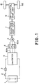
- Fig. 1 shows a drive system of a conventional electric vehicle which uses a main secondary battery (hereinafter, referred to simply as a secondary battery) as the power source.
- a secondary battery hereinafter, referred to simply as a secondary battery
- This figure shows a drive system for driving two wheels by a single AC motor.
- the reference numeral 1 designates a secondary battery
- the reference numeral 2 denotes a main contactor
- the reference numeral 3 designates a fuse
- the reference numeral 4 denotes an inverter
- the reference numeral 5 designates an AC motor
- the reference numeral 6 denotes a triple pole contactor for opening a motor circuit
- the reference numeral 7 designates a reduction gear unit
- the reference numeral 9 denotes a differential gear unit.
- the inverter 4 is connected to the motor 5 through lines 60a, the triple pole contactor 6, and lines 60b, so that the triple pole contactor 6 breaks the lines 60a and 60b if a fault occurs on the side of the motor 5.
- the inverter 4 inverts the DC power of the secondary battery 1 into AC power, thereby controlling both the torque and rotating speed of the AC motor 5.
- the power is supplied from the secondary battery 1 to the motor 5 via the inverter 4 which inverts the DC power into the AC power, so that the wheels 81 and 82, namely, the vehicle body is driven.
- the kinetic energy of the vehicle body is regenerated to the secondary battery 1 via the wheels 81, 82, the motor 5, and the inverter 4 which converts AC to DC in the direction opposite to that during the power running.
- the inverter of the electric vehicle is arranged in the form of a 3-phase transistor inverter as shown in Fig. 2.
- the reference numeral 401 designates a transistor
- the reference numeral 402 denotes a diode connected in antiparallel to the transistor 401.
- the major circuit of the 3-phase inverter is composed of six arms, each of which consists of the switching element combining the transistor 401 and the diodes 402.
- the reference numeral 403 designates a capacitor for smoothing the current from the secondary battery 1.
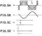
- Figs. 4A - 5D illustrate voltage waveforms and current waveforms of respective portions of the drive system during the drive operation of the electric vehicle.
- the inverter for driving the electric vehicle employs the same PWM control as industrial AC motor driving systems.
- These figures illustrate the PWM control method.
- Fig. 3 shows a circuit arrangement for explaining the voltages and currents in Figs. 4A - 4D (the power running operation mode), and Figs. 5A - 5D (the regenerative braking operation mode).
- the voltage V B of the secondary battery 1 is subjected to the PWM control by the inverter 4 to be converted to the AC-side voltage V M of the inverter 4, which takes such a waveform as shown in Fig. 4A.
- the waveforms during the power running operation and regenerative braking operation are similar.
- a waveform indicated by a dotted line in Fig. 4A represents a fundamental wave of the PWM control.
- the PWM control is carried out in such a manner that this fundamental waveform becomes a sine wave.
- the AC-side current i M of the inverter 4 takes such a waveform as superimposing higher harmonic currents on the fundamental wave current.
- Figs. 4A - 5D are when the power factor of the fundamental waves is 1.
- the phases of the currents during the braking operation mode (Figs. 5A - 5D) and the power running operation mode (Figs. 4A - 4D) are opposite, and hence, the braking operation becomes the regenerative operation.
- the polarity of the DC-side current i B is also inverted during the braking operation.
- the charging operation of the secondary battery and a charging device are essential in using electric vehicles.
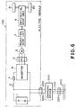
- Fig. 6 shows a conventional charging system.
- the reference numeral 100 designates an electric vehicle, in which the same reference numerals are used as in Fig. 1.
- the reference numeral 300 denotes a charging device connected to the secondary battery 1 via a charging cable 400 and a charging connector 200 which is connected to the secondary battery 1.
- the charging device 300 is connected to a connector 200 of an external power distribution system 240 via a cable 700.
- the main switch 2 of the electric vehicle 100 is opened, so that the secondary battery 1 is charged with the power from the power distribution system 240 using the charging device 300.
- Fig. 7 shows the conventional charging device 300.
- the reference numeral 301 designates an AC-side contactor
- the reference numeral 302 denotes a step-down transformer provided as necessary
- the reference numeral 303 designates a diode rectifier for converting an AC voltage into a DC voltage
- the reference numeral 304 denotes a chopper controlling a charging current
- the reference numeral 305 denotes a reactor for smoothing a charging current
- the reference numeral 306 designates a fuse.
- the charging device must charge the secondary battery 1 quickly. Therefore, the capacity of the charging device 300 must be selected to be equal to or greater than that of the inverter for driving the AC motor of the electric vehicle. Thus, the charging device 300 must be necessarily made bulky, and the charging operation becomes complicated, because the charging device must have a large capacity, and include the power converter such as the diode rectifier 300, as well.
- the charging device 300 has the rectifier load which is connected to the power distribution system 240. This presents another problem in that it will deteriorate the quality of power by causing higher harmonic waves in the power distribution system 240, and reducing the power factor.
- the present invention has been made by taking account of the fact that a large-capacity inverter with regenerative function is installed in an electric vehicle, and the inverter is not conventionally used for charging a secondary battery.
- the electric vehicle In a normal mode, the electric vehicle is driven by an AC motor which is supplied with power from the inverter.
- the inverter In a charging mode, the inverter functions as an AC-to-DC power converter.
- a contactor is used to disconnect the motor from the inverter during the charging of the secondary battery.
- the contactor has first terminals and second terminals, the first terminals are connected to second terminals of the windings of the AC motor, and second terminals of the contactor are shortcircuited.
- the first terminals of the windings of the AC motor is connected to AC side of the inverter.
- the contactor is opened so that the AC motor is stopped and an AC voltage fed from an external AC power source is supplied to the inverter via the windings of the AC motor functioning as reactors.
- the inverter operates as an AC-to-DC converter, and charges the secondary battery.
- the contactor is closed so that the windings are Y connected and function as the windings of the motor. In this case, charging lines led to the charging connectors are shortcircuited, and the charging operation of the secondary battery becomes impossible.
- the external AC power source may be either of a single-phase or a 3-phase power distribution system. It is preferable to insert a fuse between the power converter and the power distribution system.
- a voltage peak value of the charging AC power source is preferably selected to be lower than the voltage of the secondary battery.
- the wheels be automatically braked in order to prevent the electric vehicle from starting.
- the potential of the secondary battery is not equal to that of the power distribution system because the secondary battery is insulated from the power distribution system by an insulating transformer (step-down transformer) during the charging operation.
- the potential of the secondary battery equals that of the power distribution system.
- Fig. 16 is an explanatory diagram of the charging operation according to the present invention.
- the body 110 of the electric vehicle is insulated from the ground 242 by means of tires 120.
- the reference numerals 121 and 122 designate stray capacitances between the vehicle body 110 and main circuit connecting lines that connect the secondary battery 1 to inverter 4, and the reference numeral 123 denotes a stray capacitance between the vehicle body 110 and the ground 242.
- one of the lines or the neutral line of a power distribution system 240 is connected to the ground 242 through a ground line 251 on the side of the AC power source 250 such as a system transformer.
- Fig. 17 shows the potential of the vehicle during the charging operation of the secondary battery.
- Vs is the potential of the power distribution system 240 with regard to the ground
- C S1 is a combined capacitance value of the stray capacitances 121 and 122
- C S2 is a capacitance value of the stray capacitance 123.
- the vehicle body 110 of the electric vehicle is connected to the ground through the charging connector and the charging cable, so that the ground potential of the vehicle body 110 under charging operation is set at zero.
- the secondary battery is charged while the contactor is opened and the AC side of the inverter functioning as the power converter is connected via the windings of the AC motor to the power distribution system functioning as the charging AC power source.
- the inverter operates in a manner similar to the regenerative braking operation of a conventional inverter, in which the AC power is converted into DC power.
- the secondary battery is charged.
- the voltage of the secondary battery is preferably selected to be higher than the sinusoidal peak value of the AC-side voltage of the inverter. If the sinusoidal peak value becomes higher than the battery voltage, the AC-side voltage of the inverter should be reduced by using a step-down transformer.
- the contactor When the electric vehicle is driven, the contactor is closed, so that the windings of the motor are normally connected, and the motor functions as the AC motor for driving the wheels.
- the windings of the AC motor which are connected between the inverter and the AC power source during the charging operation of the secondary battery, function as reactances for greatly suppressing the higher harmonic voltages induced by the PWM control of the inverter, the distortion of the current waveform of the AC power source is greatly reduced, resulting in a suitable waveform. Furthermore, disturbing influence of the voltage waveform caused by the PWM control on the AC power distribution system can also be greatly reduced.
- the vehicle body of the electric vehicle since the vehicle body of the electric vehicle is grounded during the charging operation of the secondary battery, the vehicle body of the electric vehicle is not charged to such a potential as may cause a risk to a human body.
- a large-scale, large-capacity conventional charging device containing an AC/DC power converter is not required.
- a low cost, compact, space saving electric system including the charging system can be implemented, which will greatly serve to widely spread the electric vehicle.
- the higher order harmonic waves and distortion can be reduced by employing a control method of the power converter such as the PWM control.
- the charging device can be operated under unity power factor. This will serve to improve the power quality of the power distribution system.
- a single-phase or a 3-phase AC power source may be used as the charging AC power source, a domestic power source as well as an industrial power source may be readily employed, thereby removing a restriction on the power supply.
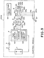
- Fig. 9 shows an arrangement of a major portion of an embodiment in accordance with the present invention.
- like portions are designated by the same reference numerals as in Fig. 1, and the description thereof is omitted.
- the inverter 4 functions as a power converter performing forward/reverse conversions, having the regenerative function.
- the AC-side connecting lines 60a of the inverter 4 are connected to terminals 51a, 52a and 53a of the phase windings 51, 52 and 53 of the AC motor 5, respectively.
- the other terminals 51b, 52b and 53b of the windings 51, 52 and 53 are connected to terminals 61a, 62a and 63a of the triple pole contactor 6 via the connecting lines 60b, respectively.
- the other terminals 61b, 62b and 63b of the triple pole contactor 6 are connected to a shortcircuit line 65, so that these terminals are shortcircuited.
- the terminals of charging connecting lines 66 are connected to the terminals of the triple pole contactor 6, respectively, and the other terminals of the lines 66 are connected to a charging connector 210a.
- One terminal of a vehicle-body ground line 67 is connected to the charging connector 210a, and the other terminal of this ground line 67 is connected to a vehicle-body ground line connecting unit 68 of the vehicle body 110.
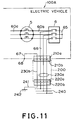
- Fig. 10 shows this condition in which the ends 51a, 52a and 53a of motor windings 51, 52 and 53 are shortcircuited by the shortcircuit line 65 via the contactor 6, and the windings 51, 52 and 53 form a Y connection.
- the motor 5 is driven by the inverter 4 as the Y-connection motor, and is operated as a normal motor for driving the electric vehicle.
- the charging operation of the secondary battery 1 will be explained.
- the triple pole contactor 6 is opened while the inverter 4 is not operated.
- the charging connector 210b of the charging cable 200 is connected to the charging connector 210a.
- the charging cable 200 comprises the connector 210b, a connector 220a connected to a connector 220b on the side of the power distribution system 240, and connecting lines consisting of the charging connecting lines 230a and ground connecting line 230b, which connect the connectors 210a and 220a.
- the charging connecting lines 230a are connected to the power distribution system 240 via the connectors 220a and 220b, whereas the ground connecting line 230b is connected to the ground line 241 via the connectors 220a and 220b.
- This ground line 241 is connected to earth 242.
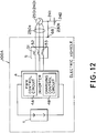
- Fig. 12 is a circuit diagram illustrating the charging operation.
- the windings 51, 52 and 53 of the motor function as reactors.
- the charging power is supplied from an AC power source 250 of the power distribution system 240 to the inverter 4 via the windings 51, 52 and 53.
- the inverter 4 converts the AC power into the DC power to charge the secondary battery 1 in operation similar to that during the above-described regenerative braking operation.
- the inverter 4 includes a PWM control circuit 4A for performing the PWM control, and a charging control circuit 4B for controlling the charging operation.
- the charging control circuit 4B controls the battery current and battery voltage during charging operation.
- a protection circuit 6A is provided for detecting a failure of inverter operation and the motor during the power running of the electric vehicle. The protection circuit 6A opens the contactor 6 when a failure is detected.
- the neutral line or one of the lines of the power distribution system 240 is grounded to earth 242 via the ground line 241.
- the vehicle body 110 of the electric vehicle 100A is also grounded through a ground line connecting portion 68, the ground connecting line 230b, and the ground line 241.
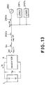
- Fig. 13 shows an equivalent circuit for charging the secondary battery in this embodiment
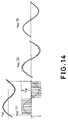
- Fig. 14 shows voltage/current waveforms of various portions in Fig. 13.
- the reference numeral 5x denotes the reactance of the windings 51, 52 and 53 of the motor 5
- the reference numeral 200x denotes the reactance of the charging cable 200
- the reference numeral 240x designates the reactance of the power distribution system 240
- the reference numerals 241L and 242L designate other AC loads connected to the power distribution system 240.
- V B is the voltage of the secondary battery 1
- i B is the current of the secondary battery 1 during the charging operation
- i AC is the AC-side current of the inverter 4 during the charging operation
- V AC is the AC-side voltage of the inverter 4.
- the inverter 4 is PWM-controlled by a frequency higher than several kHz, the current i AC supplied from the power distribution system 240 becomes a sinusoidal current whose power factor is approximately 1, with a small amount of high-frequency ripples, as shown in Fig. 14.
- the AC-side voltage V AC of the inverter 4 has a PWM waveform, the peak value of which is equal to the battery voltage V B , as indicated by V AC [1].
- the phase windings of the AC motor are interposed between the external AC power source and the inverter for driving the AC motor.
- the secondary battery is charged by the inverter to which the power is supplied from the external AC power source.
- Fig. 15 is an equivalent circuit of a major portion when an induction motor is employed as the AC motor 5.
- the equivalent circuit of the AC motor (induction motor) 5 itself is well known.
- X1 and R1 are the leakage reactance and the winding resistance of the stator windings. Normally, since X1>>R1, the winding resistance R1 is negligible.
- X2' and R2' are the reactance and the resistance of a rotor. S is a slip, Xm is a exciting reactance, V is a voltage applied to the motor 5, and Vm is an exciting voltage in the voltage V.
- X1 + X2' is on the order of 10% in terms of % reactance. This means that the motor voltage V is on the order of 10% of the rated voltage when the current I AC during the charging operation is equal to the rated current of the motor 5. Furthermore, since X1 and X2' are substantially equal to each other, the exciting voltage Vm is on the order of 5% of the rated voltage.
- the torque produced by an induction motor is proportional to the square of the voltage
- the torque produced during the charging operation is equal to the rated torque multiplied by (5/100)2, that is, 0.25% of the rated torque.
- the torque acting on the rotor of a permanent magnet synchronous motor is proportional to the motor current because the magnetic flux of the rotor is constant.
- the motor current is an AC current having a frequency of a commercial power source. Accordingly, average torque acting on the rotor becomes zero, and hence, no torque to move the electric vehicle is produced.
- the charging voltage of the secondary battery 1 is preferably selected to be higher than the AC-side voltage of the inverter 4, namely the sinusoidal peak value of the AC voltage of the power source 250 in the power distribution system 240.
- the inverter 4 which has not been used during the conventional charging operation, is utilized as the AC-to-DC converting apparatus to charge the secondary battery 1.
- the power factor one charging operation becomes possible by PWM controlling the inverter 4 because the current i AC supplied from the power distribution system 240 to the electric vehicle 100 during the charging operation becomes a nearly perfect sine wave with little distortion as illustrated in Fig. 14. As a result, there is no risk of the power quality of the power distribution system 240 to be degraded.
- the external AC power source is the 3-phase power distribution system 240 in the embodiment describe above, the present invention can also be applied to an external power source of a single phase power distribution system.
Abstract
Description
- The present invention relates to an electric system of an electric vehicle using a main secondary battery as a power source.
- Fig. 1 shows a drive system of a conventional electric vehicle which uses a main secondary battery (hereinafter, referred to simply as a secondary battery) as the power source. This figure shows a drive system for driving two wheels by a single AC motor. In Fig. 1, the
reference numeral 1 designates a secondary battery, thereference numeral 2 denotes a main contactor, thereference numeral 3 designates a fuse, thereference numeral 4 denotes an inverter, thereference numeral 5 designates an AC motor, thereference numeral 6 denotes a triple pole contactor for opening a motor circuit, thereference numeral 7 designates a reduction gear unit, and thereference numeral 9 denotes a differential gear unit. - In this drive system, the rotation of the
AC motor 5 is decelerated by thereduction gear unit 7, and the decelerated rotation is transferred to thewheels differential gear unit 9. - The
inverter 4 is connected to themotor 5 throughlines 60a, thetriple pole contactor 6, andlines 60b, so that thetriple pole contactor 6 breaks thelines motor 5. - In the drive system shown in Fig. 1, the
inverter 4 inverts the DC power of thesecondary battery 1 into AC power, thereby controlling both the torque and rotating speed of theAC motor 5. - During the power running of the electric vehicle, the power is supplied from the
secondary battery 1 to themotor 5 via theinverter 4 which inverts the DC power into the AC power, so that thewheels secondary battery 1 via thewheels motor 5, and theinverter 4 which converts AC to DC in the direction opposite to that during the power running. - In general, the inverter of the electric vehicle is arranged in the form of a 3-phase transistor inverter as shown in Fig. 2.
- In Fig. 2, the
reference numeral 401 designates a transistor, thereference numeral 402 denotes a diode connected in antiparallel to thetransistor 401. The major circuit of the 3-phase inverter is composed of six arms, each of which consists of the switching element combining thetransistor 401 and thediodes 402. Thereference numeral 403 designates a capacitor for smoothing the current from thesecondary battery 1. - Figs. 4A - 5D illustrate voltage waveforms and current waveforms of respective portions of the drive system during the drive operation of the electric vehicle. Generally speaking, the inverter for driving the electric vehicle employs the same PWM control as industrial AC motor driving systems. These figures illustrate the PWM control method. It should be noted that Fig. 3 shows a circuit arrangement for explaining the voltages and currents in Figs. 4A - 4D (the power running operation mode), and Figs. 5A - 5D (the regenerative braking operation mode).
- As apparent from Figs. 4A - 5D, the voltage VB of the
secondary battery 1 is subjected to the PWM control by theinverter 4 to be converted to the AC-side voltage VM of theinverter 4, which takes such a waveform as shown in Fig. 4A. The waveforms during the power running operation and regenerative braking operation are similar. A waveform indicated by a dotted line in Fig. 4A represents a fundamental wave of the PWM control. The PWM control is carried out in such a manner that this fundamental waveform becomes a sine wave. Thus, the AC-side current iM of theinverter 4 takes such a waveform as superimposing higher harmonic currents on the fundamental wave current. - The examples shown in Figs. 4A - 5D are when the power factor of the fundamental waves is 1. As shown in these figures, the phases of the currents during the braking operation mode (Figs. 5A - 5D) and the power running operation mode (Figs. 4A - 4D) are opposite, and hence, the braking operation becomes the regenerative operation. Similarly, the polarity of the DC-side current iB is also inverted during the braking operation.
- Since the stored energy of the secondary battery on an electric vehicle is finite as the power source, the battery must be properly recharged. This battery charging operation is a major problem in using electric vehicles.
- In other words, the charging operation of the secondary battery and a charging device are essential in using electric vehicles.
- Fig. 6 shows a conventional charging system. The
reference numeral 100 designates an electric vehicle, in which the same reference numerals are used as in Fig. 1. - In Fig. 6, the
reference numeral 300 denotes a charging device connected to thesecondary battery 1 via acharging cable 400 and acharging connector 200 which is connected to thesecondary battery 1. Thecharging device 300 is connected to aconnector 200 of an externalpower distribution system 240 via acable 700. - During the charging operation, the
main switch 2 of theelectric vehicle 100 is opened, so that thesecondary battery 1 is charged with the power from thepower distribution system 240 using thecharging device 300. - Fig. 7 shows the
conventional charging device 300. In this figure, thereference numeral 301 designates an AC-side contactor, thereference numeral 302 denotes a step-down transformer provided as necessary, thereference numeral 303 designates a diode rectifier for converting an AC voltage into a DC voltage, thereference numeral 304 denotes a chopper controlling a charging current, thereference numeral 305 denotes a reactor for smoothing a charging current, and thereference numeral 306 designates a fuse. - Generally, the charging device must charge the
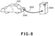
secondary battery 1 quickly. Therefore, the capacity of thecharging device 300 must be selected to be equal to or greater than that of the inverter for driving the AC motor of the electric vehicle. Thus, thecharging device 300 must be necessarily made bulky, and the charging operation becomes complicated, because the charging device must have a large capacity, and include the power converter such as thediode rectifier 300, as well. - It is essential for driving electric vehicles regardless of time and space to install a charging station as shown in Fig. 8 at many places as gasoline stations for internal combustion engines.
- However, it is difficult to install the above-explained conventional charging system at a large number of places, because the
charging device 300 is bulky and expensive. This presents a problem in widely spreading the electric vehicles. - Furthermore, the
charging device 300 has the rectifier load which is connected to thepower distribution system 240. This presents another problem in that it will deteriorate the quality of power by causing higher harmonic waves in thepower distribution system 240, and reducing the power factor. - It is therefore an object of the present invention to provide an electric system of an electric vehicle, which is capable of charging a secondary battery by merely being connected to an external AC power source like a power distribution system without employing a bulky and expensive charging device, and which is also capable of preventing a power quality of the power distribution system from being deteriorated during the charging operation, thereby eliminating the above-described problems.
- The present invention has been made by taking account of the fact that a large-capacity inverter with regenerative function is installed in an electric vehicle, and the inverter is not conventionally used for charging a secondary battery. In a normal mode, the electric vehicle is driven by an AC motor which is supplied with power from the inverter. In a charging mode, the inverter functions as an AC-to-DC power converter. A contactor is used to disconnect the motor from the inverter during the charging of the secondary battery.
- More specifically, the contactor has first terminals and second terminals, the first terminals are connected to second terminals of the windings of the AC motor, and second terminals of the contactor are shortcircuited. The first terminals of the windings of the AC motor is connected to AC side of the inverter.
- During charging of the secondary battery, the contactor is opened so that the AC motor is stopped and an AC voltage fed from an external AC power source is supplied to the inverter via the windings of the AC motor functioning as reactors. The inverter operates as an AC-to-DC converter, and charges the secondary battery.
- On the other hand, when the motor drives the wheels, the contactor is closed so that the windings are Y connected and function as the windings of the motor. In this case, charging lines led to the charging connectors are shortcircuited, and the charging operation of the secondary battery becomes impossible. During the charging operation of the secondary battery, it is preferable to PWM-control the power converter by a control circuit to improve current waveforms. The external AC power source may be either of a single-phase or a 3-phase power distribution system. It is preferable to insert a fuse between the power converter and the power distribution system.
- A voltage peak value of the charging AC power source is preferably selected to be lower than the voltage of the secondary battery. During the charging operation of the secondary battery, it is also preferable that the wheels be automatically braked in order to prevent the electric vehicle from starting.
- During the charging operation of the secondary battery, an electric shock to a human body must be prevented. For this purpose, a part of the body of the electric vehicle, on which one may touch during the charging operation, is grounded so that the body is kept at the ground potential.
- In the conventional charging system as shown in Figs. 6 and 16, the potential of the secondary battery is not equal to that of the power distribution system because the secondary battery is insulated from the power distribution system by an insulating transformer (step-down transformer) during the charging operation. In contrast, in the present invention, since the secondary battery is charged directly from the power distribution system rather than via the insulating transformer, the potential of the secondary battery equals that of the power distribution system.
- Fig. 16 is an explanatory diagram of the charging operation according to the present invention. The
body 110 of the electric vehicle is insulated from theground 242 by means oftires 120. Thereference numerals vehicle body 110 and main circuit connecting lines that connect thesecondary battery 1 toinverter 4, and thereference numeral 123 denotes a stray capacitance between thevehicle body 110 and theground 242. - On the other hand, one of the lines or the neutral line of a
power distribution system 240 is connected to theground 242 through aground line 251 on the side of theAC power source 250 such as a system transformer. - Fig. 17 shows the potential of the vehicle during the charging operation of the secondary battery. In this figure, Vs is the potential of the
power distribution system 240 with regard to the ground, CS1 is a combined capacitance value of thestray capacitances stray capacitance 123. From this figure, the ground potential V₁₁₀ of thevehicle body 110 is given by the following formula:

From this formula, in order to set the ground potential V₁₁₀ of thevehicle body 110 to zero during the charging operation, the capacitance value CS2 must be equivalently set at infinite value. - Therefore, according to the present invention, during the charging operation of the secondary battery, the
vehicle body 110 of the electric vehicle is connected to the ground through the charging connector and the charging cable, so that the ground potential of thevehicle body 110 under charging operation is set at zero. - In accordance with the present invention, the secondary battery is charged while the contactor is opened and the AC side of the inverter functioning as the power converter is connected via the windings of the AC motor to the power distribution system functioning as the charging AC power source. In this case, the inverter operates in a manner similar to the regenerative braking operation of a conventional inverter, in which the AC power is converted into DC power. Thus, the secondary battery is charged.
- The voltage of the secondary battery is preferably selected to be higher than the sinusoidal peak value of the AC-side voltage of the inverter. If the sinusoidal peak value becomes higher than the battery voltage, the AC-side voltage of the inverter should be reduced by using a step-down transformer.
- When the electric vehicle is driven, the contactor is closed, so that the windings of the motor are normally connected, and the motor functions as the AC motor for driving the wheels.
- Since the windings of the AC motor, which are connected between the inverter and the AC power source during the charging operation of the secondary battery, function as reactances for greatly suppressing the higher harmonic voltages induced by the PWM control of the inverter, the distortion of the current waveform of the AC power source is greatly reduced, resulting in a suitable waveform. Furthermore, disturbing influence of the voltage waveform caused by the PWM control on the AC power distribution system can also be greatly reduced.
- Moreover, in accordance with the present invention, since the vehicle body of the electric vehicle is grounded during the charging operation of the secondary battery, the vehicle body of the electric vehicle is not charged to such a potential as may cause a risk to a human body.
- According to the present invention, a large-scale, large-capacity conventional charging device containing an AC/DC power converter is not required. A low cost, compact, space saving electric system including the charging system can be implemented, which will greatly serve to widely spread the electric vehicle.
- During the charging operation, since the reactances of the windings of the AC motor is utilized, the higher order harmonic waves and distortion can be reduced by employing a control method of the power converter such as the PWM control. In addition, the charging device can be operated under unity power factor. This will serve to improve the power quality of the power distribution system.
- Since either a single-phase or a 3-phase AC power source may be used as the charging AC power source, a domestic power source as well as an industrial power source may be readily employed, thereby removing a restriction on the power supply.
- In addition, since the vehicle body of the electric vehicle is grounded through the grounding line within the charging cable and the charging connector during the charging operation of the secondary battery, there is no possibility that the vehicle body is charged during the charging operation. As a result, it is possible to provide a safety charging system for a human body.
- The above and other objects, effects, features and advantages of the present invention will become more apparent from the following description of the embodiment thereof taken in conjunction with the accompanying drawings.
- Fig. 1 is a diagram showing a drive system of a conventional electric vehicle;
- Fig. 2 is circuit diagram showing a major circuit of a 3-phase transistor inverter;
- Fig. 3 is a circuit diagram showing voltages and currents of major portions of Fig. 1;
- Figs. 4A - 4D illustrate voltage and current waveforms during the power running mode of the electric vehicle;
- Figs. 5A - 5D illustrate voltage and current waveforms during the regenerative braking mode of the electric vehicle;
- Fig. 6 is a circuit diagram showing a conventional charging system;
- Fig. 7 is a block diagram showing the arrangement of a conventional charging device;
- Fig. 8 is a schematic diagram illustrating a conventional charging operation;
- Fig. 9 is a circuit diagram showing one embodiment of an electric system of an electric vehicle in accordance with the present invention;
- Fig. 10 is a circuit diagram showing a major portion of the embodiment during the power running;
- Fig. 11 is a circuit diagram showing the major portion of the embodiment during the charging operation;
- Fig. 12 is a schematic circuit diagram showing the connection during the charging operation in the embodiment of Fig. 9;
- Fig. 13 is an equivalent circuit diagram during the charging operation in the embodiment of Fig. 9;
- Fig. 14 is a diagram illustrating voltage and current waveforms at various portions of Fig. 13;
- Fig. 15 is an equivalent circuit diagram of the major portion when an induction motor is employed as an AC motor in the embodiment of Fig. 9;
- Fig. 16 is an equivalent circuit diagram during the charging operation in the embodiment of Fig. 9; and
- Fig. 17 is a circuit diagram illustrating the vehicle body potential in Fig. 16.
- The invention will now be described with reference to the accompanying drawings.
- Fig. 9 shows an arrangement of a major portion of an embodiment in accordance with the present invention. In Fig. 9, like portions are designated by the same reference numerals as in Fig. 1, and the description thereof is omitted.
- In an
electric vehicle 100A according to this embodiment, theinverter 4 functions as a power converter performing forward/reverse conversions, having the regenerative function. The AC-side connecting lines 60a of theinverter 4 are connected toterminals phase windings AC motor 5, respectively. Theother terminals windings terminals triple pole contactor 6 via the connectinglines 60b, respectively. Theother terminals triple pole contactor 6 are connected to ashortcircuit line 65, so that these terminals are shortcircuited. - The terminals of charging connecting
lines 66 are connected to the terminals of thetriple pole contactor 6, respectively, and the other terminals of thelines 66 are connected to a chargingconnector 210a. One terminal of a vehicle-body ground line 67 is connected to the chargingconnector 210a, and the other terminal of thisground line 67 is connected to a vehicle-body groundline connecting unit 68 of thevehicle body 110. - Next, the operation of this embodiment will be described.
- First, the
electric vehicle 100A is driven by closing thetriple pole contactor 6. Fig. 10 shows this condition in which theends motor windings shortcircuit line 65 via thecontactor 6, and thewindings motor 5 is driven by theinverter 4 as the Y-connection motor, and is operated as a normal motor for driving the electric vehicle. - During the driving operation, no component is connected to
terminals connector 210a and aground terminal 214a. When thetriple pole contactor 6 is closed, the charging connectinglines 66 are shortcircuited, and hence, the terminals of the chargingconnector 210a are also shortcircuited. As a result, the motor voltages do not appear to theterminals - On the other hand, when an abnormal operation such as a fault occurs during the drive operation of the electric vehicle, a protection circuit (not shown) becomes operative in response to this abnormal operation. This will open the
triple pole contactor 6. At this time, although the voltages of the motor appear between theterminals connector 210a, this presents no problem in terms of safety because the abnormal operation is immediately removed either by interrupting the operation of the inverter, or by opening themain contactor 2 and thefuse 3. - Next, referring now to Fig. 11, the charging operation of the
secondary battery 1 will be explained. First, thetriple pole contactor 6 is opened while theinverter 4 is not operated. Thereafter, the chargingconnector 210b of the chargingcable 200 is connected to the chargingconnector 210a. - In Fig. 11, the charging
cable 200 comprises theconnector 210b, aconnector 220a connected to aconnector 220b on the side of thepower distribution system 240, and connecting lines consisting of thecharging connecting lines 230a andground connecting line 230b, which connect theconnectors - Here, the charging connecting
lines 230a are connected to thepower distribution system 240 via theconnectors ground connecting line 230b is connected to theground line 241 via theconnectors ground line 241 is connected toearth 242. - Fig. 12 is a circuit diagram illustrating the charging operation. The
windings AC power source 250 of thepower distribution system 240 to theinverter 4 via thewindings inverter 4 converts the AC power into the DC power to charge thesecondary battery 1 in operation similar to that during the above-described regenerative braking operation. - The
inverter 4 includes aPWM control circuit 4A for performing the PWM control, and a chargingcontrol circuit 4B for controlling the charging operation. The chargingcontrol circuit 4B controls the battery current and battery voltage during charging operation. In addition, aprotection circuit 6A is provided for detecting a failure of inverter operation and the motor during the power running of the electric vehicle. Theprotection circuit 6A opens thecontactor 6 when a failure is detected. - The neutral line or one of the lines of the
power distribution system 240 is grounded toearth 242 via theground line 241. Thevehicle body 110 of theelectric vehicle 100A is also grounded through a groundline connecting portion 68, theground connecting line 230b, and theground line 241. - Fig. 13 shows an equivalent circuit for charging the secondary battery in this embodiment, and Fig. 14 shows voltage/current waveforms of various portions in Fig. 13.
- In Fig. 13, the
reference numeral 5x denotes the reactance of thewindings motor 5, thereference numeral 200x denotes the reactance of the chargingcable 200, thereference numeral 240x designates the reactance of thepower distribution system 240, and thereference numerals power distribution system 240. - In addition, VB is the voltage of the
secondary battery 1, iB is the current of thesecondary battery 1 during the charging operation, iAC is the AC-side current of theinverter 4 during the charging operation, and VAC is the AC-side voltage of theinverter 4. - In general, since the
inverter 4 is PWM-controlled by a frequency higher than several kHz, the current iAC supplied from thepower distribution system 240 becomes a sinusoidal current whose power factor is approximately 1, with a small amount of high-frequency ripples, as shown in Fig. 14. - The AC-side voltage VAC of the
inverter 4 has a PWM waveform, the peak value of which is equal to the battery voltage VB, as indicated by VAC[1]. - Since the
reactance 5x is much greater than thereactance reactance 5x, and a voltage at theconnectors electric vehicle 100A becomes close to a sine wave as indicated by VAC[2]. A voltage at theconnectors power distribution system 240 further approaches a sine wave, as indicated by VAC[3]. - Since the power source voltage applied to
other AC load power distribution system 240 is close to a sine wave as shown by VAC[3], the charging operation of theelectric vehicle 100A has substantially no influence on the power source system. - As previously explained, in accordance with the present invention, the phase windings of the AC motor are interposed between the external AC power source and the inverter for driving the AC motor. Thus, using the reactance of the phase windings, the secondary battery is charged by the inverter to which the power is supplied from the external AC power source.
- It must be fully considered that the electric vehicle should never start to move during the charging operation by producing torque.
- This will be described in more detail. First, a description will be made when an induction motor is used.
- Fig. 15 is an equivalent circuit of a major portion when an induction motor is employed as the
AC motor 5. The equivalent circuit of the AC motor (induction motor) 5 itself is well known. - In this figure, X₁ and R₁ are the leakage reactance and the winding resistance of the stator windings. Normally, since X₁>>R₁, the winding resistance R₁ is negligible. X₂' and R₂' are the reactance and the resistance of a rotor. S is a slip, Xm is a exciting reactance, V is a voltage applied to the
motor 5, and Vm is an exciting voltage in the voltage V. - During the charging operation of the
secondary battery 1, the electric vehicle is stopped. In this case, the slip S is 1.0 because the rotation frequency is zero. Normally,
- Normally, X₁ + X₂' is on the order of 10% in terms of % reactance. This means that the motor voltage V is on the order of 10% of the rated voltage when the current IAC during the charging operation is equal to the rated current of the
motor 5. Furthermore, since X₁ and X₂' are substantially equal to each other, the exciting voltage Vm is on the order of 5% of the rated voltage. - Since the torque produced by an induction motor is proportional to the square of the voltage, the torque produced during the charging operation is equal to the rated torque multiplied by (5/100)², that is, 0.25% of the rated torque.
- As apparent from the foregoing explanation, there is no risk that an electric vehicle starts to move because the produced torque by the induction motor is very small.
- Next, the case will be described in which a permanent magnet synchronous motor is employed as the
AC motor 5. - The torque acting on the rotor of a permanent magnet synchronous motor is proportional to the motor current because the magnetic flux of the rotor is constant. During the charging operation of this embodiment, however, no torque to move the electric vehicle is produced because the rotor is being stopped and the motor current is an AC current having a frequency of a commercial power source. Accordingly, average torque acting on the rotor becomes zero, and hence, no torque to move the electric vehicle is produced.
- Thus, since the torque generated during the charging operation of this embodiment is very small, there is no risk of the electric vehicle to start to move. Of course, it is preferable to use braking control (parking brake) during the charging operation for the sake of safety.
- It should be noted that during the charging operation, the charging voltage of the
secondary battery 1 is preferably selected to be higher than the AC-side voltage of theinverter 4, namely the sinusoidal peak value of the AC voltage of thepower source 250 in thepower distribution system 240. - This is because if the battery voltage would be lower than the sinusoidal peak value, an excessive and uncontrollable charging current would flow through the diodes constituting the
inverter 4, and hence thefuse 3 would be melted down due to the excessive current, thereby the charging circuit would be opened. A battery voltage slightly lower than the peak value, however, is allowable because this excessive current is suppressed by the internal resistance of the battery. - Although not shown in the drawing, it is preferable to interpose a protection device such as a fuse between the
power distribution system 240 and the AC side of theinverter 4 in order to protect the circuit during the charging operation
According to this embodiment, theinverter 4, which has not been used during the conventional charging operation, is utilized as the AC-to-DC converting apparatus to charge thesecondary battery 1. - Consequently, adding only the connecting
lines connector 210a, and the charging control circuit 4a to the conventionalelectric vehicle 100, and only the chargingcable 200 to the power system enables thesecondary battery 1 to be charged. As a result, a very cheap and small charging system can be implemented. - Furthermore, the power factor one charging operation becomes possible by PWM controlling the
inverter 4 because the current iAC supplied from thepower distribution system 240 to theelectric vehicle 100 during the charging operation becomes a nearly perfect sine wave with little distortion as illustrated in Fig. 14. As a result, there is no risk of the power quality of thepower distribution system 240 to be degraded. - Although the external AC power source is the 3-phase
power distribution system 240 in the embodiment describe above, the present invention can also be applied to an external power source of a single phase power distribution system. - The present invention has been described in detail with respect to an embodiment, and it will now be apparent from the foregoing to those skilled in the art that changes and modifications may be made without departing from the invention in its broader aspects, and it is the intention, therefore, in the appended claims to cover all such changes and modifications as fall within the true spirit of the invention.
Claims (11)
- An electric system of an electric vehicle characterized by comprising:
a main secondary battery (1);
a power converter (4) converting DC power of the main secondary battery (1) into AC power, the power converter having a regenerative function enabling AC to DC conversion;
an AC motor (5) driving wheels (81, 82) of the electric vehicle (100A), the AC motor including windings (51, 52, 53) whose first terminals (51a, 52a, 53a) are connected to the AC side output of the power converter (4);
a switch (6) including a plurality of switching circuits, first terminals (61a, 62a, 63a) of the switching circuits being each connected to second terminals (51b, 52b, 53b) of the windings, second terminals (61b, 62b, 63b) of the switching circuits being shortcircuited; and
a charging connector (210a) to be connected to an external AC power source (240) while charging the main secondary battery (1), the charging connector being connected to the first terminals (61a, 62a, 63a) of the switching circuits of the switch (6). - The electric system of an electric vehicle as claimed in claim 1, characterized in that the charging connector (210a) comprises a ground terminal to be connected to ground (242), the ground terminal being connected to a body (110A) of the electric vehicle via a ground line (67) of the body.
- The electric system of an electric vehicle as claimed in claim 1 or 2, characterized in that the switch (6) is closed during the power running of the electric vehicle.
- The electric system of an electric vehicle as claimed in any of claims 1 to 3, characterized in that the switch (6) is opened by a protection circuit (6A) if a failure occurs during running of the electric vehicle.
- The electric system of an electric vehicle as claimed in any of claims 2 to 4, characterized in that the switch (6) is opened during the charging operation of the main secondary battery (1) so that the main secondary battery is charged via a charging cable (230a), the charging connector (210a), and the ground line (241).
- The electric system of an electric vehicle as claimed in any of claims 1 to 5, characterized in that the ground terminal of the charging connector (210a) is grounded via a ground connecting line (230b) within the charging cable.
- The electric system of an electric vehicle as claimed in any of claims 1 to 6, characterized in that the power converter (4) is PWM-controlled by a control circuit during the charging operation of the main secondary battery (1).
- The electric system of an electric vehicle as claimed in any of claims 1 to 7, characterized in that the AC power source (240) is either a single-phase or a three-phase power distribution system.
- The electric system of an electric vehicle as claimed in any of claims 1 to 8, characterized in that a voltage peak value of the AC power source (240) is determined at a value lower than the voltage of the main secondary battery (1).
- The electric system of an electric vehicle as claimed in any of claims 1 to 9, characterized in that the wheels (81, 82) are automatically braked during the charging operation of the main secondary battery (1).
- The electric system of an electric vehicle as claimed in any of claims 1 to 10, characterized in that a fuse is connected between the AC power source (240) and the AC side of the power converter (4).
Applications Claiming Priority (4)
| Application Number | Priority Date | Filing Date | Title |
|---|---|---|---|
| JP359576/92 | 1992-12-25 | ||
| JP35957692 | 1992-12-25 | ||
| JP37386/93 | 1993-02-02 | ||
| JP03738693A JP3178146B2 (en) | 1992-12-25 | 1993-02-02 | Electric vehicle electric system |
Publications (2)
| Publication Number | Publication Date |
|---|---|
| EP0603778A1 true EP0603778A1 (en) | 1994-06-29 |
| EP0603778B1 EP0603778B1 (en) | 1996-06-12 |
Family
ID=26376517
Family Applications (1)
| Application Number | Title | Priority Date | Filing Date |
|---|---|---|---|
| EP93120493A Expired - Lifetime EP0603778B1 (en) | 1992-12-25 | 1993-12-19 | Electric system of electric vehicle |
Country Status (6)
| Country | Link |
|---|---|
| US (1) | US5629603A (en) |
| EP (1) | EP0603778B1 (en) |
| JP (1) | JP3178146B2 (en) |
| KR (1) | KR0151737B1 (en) |
| CA (1) | CA2111726A1 (en) |
| DE (1) | DE69303150T2 (en) |
Cited By (23)
| Publication number | Priority date | Publication date | Assignee | Title |
|---|---|---|---|---|
| FR2735079A1 (en) * | 1995-06-09 | 1996-12-13 | Peugeot Motocycles Sa | Electrically powered vehicle with integral battery charger |
| WO1997008009A1 (en) * | 1995-08-30 | 1997-03-06 | Renault | Mixed electric power supply system comprising an inverter and an alternating-direct converter |
| EP0849112A1 (en) * | 1996-12-19 | 1998-06-24 | ASK-Antriebs-, Steuerungs- und, industrielle Kommunikationssysteme GmbH | AC traction arrangement |
| EP1201485A1 (en) * | 2000-09-08 | 2002-05-02 | Ford Motor Company | HEV charger/generator unit |
| FR2934217A1 (en) * | 2008-07-28 | 2010-01-29 | Renault Sas | ELECTRICAL DRIVE CHAIN FOR MOTOR VEHICLE. |
| FR2938711A1 (en) * | 2008-11-18 | 2010-05-21 | Valeo Sys Controle Moteur Sas | COMBINED POWER SUPPLY AND LOAD DEVICE |
| WO2010057893A1 (en) * | 2008-11-18 | 2010-05-27 | Valeo Systemes De Controle Moteur | Method and electric combined device for powering and charging with compensation means |
| WO2010079074A1 (en) | 2009-01-09 | 2010-07-15 | Robert Bosch Gmbh | Method for controlling a power supply device having a power inverter |
| WO2010103063A1 (en) * | 2009-03-11 | 2010-09-16 | Renault S.A.S. | Fast charging device for an electric vehicle |
| WO2011159241A1 (en) * | 2010-06-14 | 2011-12-22 | Aktiebolaget Chalmersinvest | Electrical apparatus comprising drive system and electrical machine with reconnectable stator winding |
| EP2400636A1 (en) | 2010-06-25 | 2011-12-28 | Valeo Systèmes de Contrôle Moteur | Alternating-current electric motor being able to be connected into the charging circuit for batteries |
| FR2961965A1 (en) * | 2010-06-25 | 2011-12-30 | Valeo Sys Controle Moteur Sas | DEVICE FOR CHARGING ACCUMULATION MEANS |
| WO2012019667A3 (en) * | 2010-07-20 | 2012-04-19 | Daimler Ag | Motor vehicle drive system having a charging device |
| WO2012019666A3 (en) * | 2010-07-20 | 2012-04-19 | Daimler Ag | Motor vehicle drive system having a charging device |
| CN102474213A (en) * | 2009-08-31 | 2012-05-23 | 大金工业株式会社 | Hybrid electric-power supplying system |
| WO2011104101A3 (en) * | 2010-02-25 | 2012-06-14 | Siemens Aktiengesellschaft | Circuit arrangement for the charging of vehicle batteries in a vehicle and associated method |
| WO2011055230A3 (en) * | 2009-11-06 | 2012-08-23 | Inda S.R.L. | Electric drive and battery-charging power electronic system |
| EP2514627A1 (en) * | 2011-04-20 | 2012-10-24 | Siemens Aktiengesellschaft | Converter for charging batteries in an electric vehicle and for feeding back to supply network |
| GB2491051A (en) * | 2012-07-19 | 2012-11-21 | P G Drives Technology Ltd | Charging system for a multi-cell power supply |
| WO2013064780A2 (en) | 2011-11-02 | 2013-05-10 | Valeo Systemes De Controle Moteur | Power module and electric device for the combined powering and charging of an accumulator and a motor respectively |
| WO2013087127A3 (en) * | 2011-12-16 | 2014-03-27 | Audi Ag | Motor vehicle |
| DE102018119810A1 (en) * | 2018-08-15 | 2019-11-14 | Voith Patent Gmbh | Vehicle electrical system with traction converter for electrically powered vehicles |
| US11722026B2 (en) | 2019-04-23 | 2023-08-08 | Dpm Technologies Inc. | Fault tolerant rotating electric machine |
Families Citing this family (59)
| Publication number | Priority date | Publication date | Assignee | Title |
|---|---|---|---|---|
| JPH08182105A (en) * | 1994-12-21 | 1996-07-12 | Toshiba Corp | Controller for electric vehicle |
| JPH08322106A (en) * | 1995-05-24 | 1996-12-03 | Matsushita Electric Ind Co Ltd | Control of motor |
| JP3373148B2 (en) * | 1998-02-26 | 2003-02-04 | エナジーサポート株式会社 | connector |
| US6885920B2 (en) * | 1999-07-30 | 2005-04-26 | Oshkosh Truck Corporation | Control system and method for electric vehicle |
| US7729831B2 (en) | 1999-07-30 | 2010-06-01 | Oshkosh Corporation | Concrete placement vehicle control system and method |
| US6757597B2 (en) * | 2001-01-31 | 2004-06-29 | Oshkosh Truck | A/C bus assembly for electronic traction vehicle |
| US7277782B2 (en) | 2001-01-31 | 2007-10-02 | Oshkosh Truck Corporation | Control system and method for electric vehicle |
| US7379797B2 (en) | 2001-01-31 | 2008-05-27 | Oshkosh Truck Corporation | System and method for braking in an electric vehicle |
| US7302320B2 (en) * | 2001-12-21 | 2007-11-27 | Oshkosh Truck Corporation | Failure mode operation for an electric vehicle |
| US7254468B2 (en) * | 2001-12-21 | 2007-08-07 | Oshkosh Truck Corporation | Multi-network control system for a vehicle |
| US7520354B2 (en) | 2002-05-02 | 2009-04-21 | Oshkosh Truck Corporation | Hybrid vehicle with combustion engine/electric motor drive |
| US7737647B2 (en) * | 2004-07-05 | 2010-06-15 | Moteurs Leroy-Somer | Rectifier and system for controlling the speed of an electric motor |
| US7439711B2 (en) * | 2004-09-27 | 2008-10-21 | Oshkosh Corporation | Energy storage device including a status indicator |
| US7332881B2 (en) | 2004-10-28 | 2008-02-19 | Textron Inc. | AC drive system for electrically operated vehicle |
| US7680642B2 (en) * | 2005-01-12 | 2010-03-16 | The Japan Research Institute, Limited | Equivalent circuit for coil incorporated in circuit simulator, circuit simulator and method of preparation of same, and storage medium of circuit simulator program |
| US8403112B2 (en) * | 2005-11-04 | 2013-03-26 | Sky Climber Llc | Hoist system with high system power factor |
| US8947531B2 (en) | 2006-06-19 | 2015-02-03 | Oshkosh Corporation | Vehicle diagnostics based on information communicated between vehicles |
| US8139109B2 (en) | 2006-06-19 | 2012-03-20 | Oshkosh Corporation | Vision system for an autonomous vehicle |
| CN101150259B (en) * | 2006-09-18 | 2010-05-12 | 比亚迪股份有限公司 | Electric car charging system |
| US20080164106A1 (en) * | 2007-01-04 | 2008-07-10 | Textron Inc. | Electric Brake for Utility Vehicles |
| US8307967B2 (en) * | 2007-07-04 | 2012-11-13 | Satyajit Patwardhan | Widely deployable charging system for vehicles |
| JP5067617B2 (en) * | 2007-09-19 | 2012-11-07 | 富士電機株式会社 | Power conversion system and electric drive vehicle |
| US7926889B2 (en) * | 2007-10-29 | 2011-04-19 | Textron Innovations Inc. | Hill hold for an electric vehicle |
| JP4822025B2 (en) * | 2008-03-26 | 2011-11-24 | 三菱自動車工業株式会社 | In-vehicle charger |
| US8684767B2 (en) | 2009-01-09 | 2014-04-01 | Mitsubishi Electric Corporation | Train information transmitting and receiving system |
| US7794280B1 (en) * | 2009-03-04 | 2010-09-14 | Gm Global Technology Operations, Inc. | Charge receptacle for plug-in electric vehicle |
| US8253376B2 (en) * | 2009-04-14 | 2012-08-28 | Ford Global Technologies, Llc | Reactive power battery charging apparatus and method of operating same |
| DE102009033185B4 (en) * | 2009-05-13 | 2014-12-31 | Avl Software And Functions Gmbh | Charging system and charging method for charging a battery of a vehicle and vehicle with such a charging system |
| US8022667B2 (en) * | 2011-02-03 | 2011-09-20 | Lawrence Everett Anderson | Electric vehicle charging system |
| US9236637B2 (en) | 2009-08-05 | 2016-01-12 | Lawrence Everett Anderson | Electric vehicle solar charging system |
| US8080970B2 (en) * | 2009-08-07 | 2011-12-20 | Larry Seever | System and apparatus for use of a 3-phase motor in a vehicle |
| DE102009046422A1 (en) * | 2009-11-05 | 2011-05-12 | Daniel Schneider | Charging system for electric vehicles |
| US8337352B2 (en) | 2010-06-22 | 2012-12-25 | Oshkosh Corporation | Electromechanical variable transmission |
| DE102010062376A1 (en) * | 2010-12-03 | 2012-06-06 | Zf Friedrichshafen Ag | Method for charging a traction battery |
| JP2012186893A (en) * | 2011-03-04 | 2012-09-27 | Honda Motor Co Ltd | Electric vehicle |
| KR101273736B1 (en) * | 2011-03-18 | 2013-06-12 | 엘에스산전 주식회사 | Inverter-charger conversed device for electric vehicles and method for controlling thereof |
| DE102011076599A1 (en) | 2011-05-27 | 2012-11-29 | Zf Friedrichshafen Ag | Electric charging system |
| DE102011076601A1 (en) | 2011-05-27 | 2012-11-29 | Zf Friedrichshafen Ag | Electric charging system |
| WO2013077888A1 (en) * | 2011-11-22 | 2013-05-30 | Quantum Fuel Systems Technologies Worldwide, Inc. | Combination charger and motive power device |
| KR20130078106A (en) * | 2011-12-30 | 2013-07-10 | 주식회사 효성 | Electric vehicle charing apparatus |
| JP5858427B2 (en) * | 2012-05-21 | 2016-02-10 | 一般財団法人電力中央研究所 | Battery-powered vehicle charging system |
| KR102011507B1 (en) * | 2012-05-24 | 2019-08-14 | 현대모비스 주식회사 | Smart Grid Electric Vehicle and Smart Grid Network System |
| FR3002384B1 (en) * | 2013-02-21 | 2016-08-19 | Valeo Systemes De Controle Moteur | ELECTRICAL ARCHITECTURE FOR THE CONVERSION OF CONTINUOUS VOLTAGE TO AN ALTERNATIVE VOLTAGE, AND RECIPROCEMENT |
| US9114804B1 (en) | 2013-03-14 | 2015-08-25 | Oshkosh Defense, Llc | Vehicle drive and method with electromechanical variable transmission |
| US10982736B2 (en) | 2015-02-17 | 2021-04-20 | Oshkosh Corporation | Multi-mode electromechanical variable transmission |
| US9651120B2 (en) | 2015-02-17 | 2017-05-16 | Oshkosh Corporation | Multi-mode electromechanical variable transmission |
| US11701959B2 (en) | 2015-02-17 | 2023-07-18 | Oshkosh Corporation | Inline electromechanical variable transmission system |
| US10584775B2 (en) | 2015-02-17 | 2020-03-10 | Oshkosh Corporation | Inline electromechanical variable transmission system |
| US10578195B2 (en) | 2015-02-17 | 2020-03-03 | Oshkosh Corporation | Inline electromechanical variable transmission system |
| US9656659B2 (en) | 2015-02-17 | 2017-05-23 | Oshkosh Corporation | Multi-mode electromechanical variable transmission |
| US10421350B2 (en) | 2015-10-20 | 2019-09-24 | Oshkosh Corporation | Inline electromechanical variable transmission system |
| US9650032B2 (en) | 2015-02-17 | 2017-05-16 | Oshkosh Corporation | Multi-mode electromechanical variable transmission |
| DE102016100358A1 (en) * | 2016-01-11 | 2017-07-13 | Volkswagen Aktiengesellschaft | Electrical system for a vehicle, vehicle and method for performing a charging process |
| DE102016106661A1 (en) | 2016-04-12 | 2017-10-12 | Dr. Ing. H.C. F. Porsche Aktiengesellschaft | Electric circuit for an electrically driven vehicle |
| DE102016213070B4 (en) * | 2016-07-18 | 2017-05-11 | Continental Automotive Gmbh | Vehicle electrical system and procedure |
| US20180280816A1 (en) * | 2017-03-28 | 2018-10-04 | Dale Acker | Motor Driven Horse Simulacrum Vehicle |
| KR20210018599A (en) * | 2019-08-06 | 2021-02-18 | 현대자동차주식회사 | System and method for charging using motor driving system |
| CN111284362B (en) * | 2020-03-17 | 2021-08-31 | 南京四象新能源科技有限公司 | Control circuit of battery management system BMS, battery management system and electric equipment |
| CA3217299A1 (en) | 2021-05-04 | 2022-11-10 | Tung Nguyen | Battery control systems and methods |
Citations (2)
| Publication number | Priority date | Publication date | Assignee | Title |
|---|---|---|---|---|
| JPS5961402A (en) * | 1982-09-30 | 1984-04-07 | Toshiba Corp | Charger for battery driven vehicle |
| EP0493848A2 (en) * | 1990-12-31 | 1992-07-08 | General Motors Corporation | Electric motor drive and power processing apparatus |
Family Cites Families (1)
| Publication number | Priority date | Publication date | Assignee | Title |
|---|---|---|---|---|
| US5214369A (en) * | 1991-12-30 | 1993-05-25 | The Charles Machine Works, Inc. | Universal battery charger |
-
1993
- 1993-02-02 JP JP03738693A patent/JP3178146B2/en not_active Expired - Lifetime
- 1993-12-17 CA CA002111726A patent/CA2111726A1/en not_active Abandoned
- 1993-12-19 DE DE69303150T patent/DE69303150T2/en not_active Expired - Fee Related
- 1993-12-19 EP EP93120493A patent/EP0603778B1/en not_active Expired - Lifetime
- 1993-12-21 US US08/170,906 patent/US5629603A/en not_active Expired - Fee Related
- 1993-12-24 KR KR1019930029484A patent/KR0151737B1/en not_active IP Right Cessation
Patent Citations (2)
| Publication number | Priority date | Publication date | Assignee | Title |
|---|---|---|---|---|
| JPS5961402A (en) * | 1982-09-30 | 1984-04-07 | Toshiba Corp | Charger for battery driven vehicle |
| EP0493848A2 (en) * | 1990-12-31 | 1992-07-08 | General Motors Corporation | Electric motor drive and power processing apparatus |
Non-Patent Citations (1)
| Title |
|---|
| PATENT ABSTRACTS OF JAPAN vol. 8, no. 166 (M - 314) 2 August 1984 (1984-08-02) * |
Cited By (48)
| Publication number | Priority date | Publication date | Assignee | Title |
|---|---|---|---|---|
| FR2735079A1 (en) * | 1995-06-09 | 1996-12-13 | Peugeot Motocycles Sa | Electrically powered vehicle with integral battery charger |
| WO1997008009A1 (en) * | 1995-08-30 | 1997-03-06 | Renault | Mixed electric power supply system comprising an inverter and an alternating-direct converter |
| FR2738411A1 (en) * | 1995-08-30 | 1997-03-07 | Renault | MIXED ELECTRIC POWER SUPPLY SYSTEM INVERTER AND CONTINUOUS-CONTINUOUS CONVERTER |
| EP0849112A1 (en) * | 1996-12-19 | 1998-06-24 | ASK-Antriebs-, Steuerungs- und, industrielle Kommunikationssysteme GmbH | AC traction arrangement |
| EP1201485A1 (en) * | 2000-09-08 | 2002-05-02 | Ford Motor Company | HEV charger/generator unit |
| CN102112338A (en) * | 2008-07-28 | 2011-06-29 | 雷诺股份公司 | Electric traction chain for an automobile |
| FR2934217A1 (en) * | 2008-07-28 | 2010-01-29 | Renault Sas | ELECTRICAL DRIVE CHAIN FOR MOTOR VEHICLE. |
| WO2010012924A2 (en) * | 2008-07-28 | 2010-02-04 | Renault S.A.S. | Electric traction chain for an automobile |
| WO2010012924A3 (en) * | 2008-07-28 | 2010-05-14 | Renault S.A.S. | Electric traction chain for an automobile |
| US20150375629A1 (en) * | 2008-11-18 | 2015-12-31 | Valeo Systemes De Controle Moteur | Method and electric combined device for powering and charging with compensation means |
| US8610383B2 (en) | 2008-11-18 | 2013-12-17 | Valco Systemes de Controle Moteur | Combined electric device for powering and charging |
| FR2938711A1 (en) * | 2008-11-18 | 2010-05-21 | Valeo Sys Controle Moteur Sas | COMBINED POWER SUPPLY AND LOAD DEVICE |
| FR2944391A1 (en) * | 2008-11-18 | 2010-10-15 | Valeo Sys Controle Moteur Sas | METHOD AND COMBINED POWER SUPPLY AND LOAD COMPENSATING DEVICE WITH COMPENSATION MEANS |
| CN102216114B (en) * | 2008-11-18 | 2014-02-26 | 法雷奥电机控制系统公司 | Method and electric combined device for powering and charging with compensation means |
| WO2010057893A1 (en) * | 2008-11-18 | 2010-05-27 | Valeo Systemes De Controle Moteur | Method and electric combined device for powering and charging with compensation means |
| US9873342B2 (en) * | 2008-11-18 | 2018-01-23 | Valeo Systemes De Controle Moteur | Method and electric combined device for powering and charging with compensation means |
| WO2010057892A1 (en) * | 2008-11-18 | 2010-05-27 | Valeo Systemes De Controle Moteur | Combined electric device for powering and charging |
| US9153996B2 (en) | 2008-11-18 | 2015-10-06 | Valeo Systemes De Controle Moteur | Method and electric combined device for powering and charging with compensation means |
| CN102216112B (en) * | 2008-11-18 | 2015-06-03 | 法雷奥电机控制系统公司 | Combined electric device for powering and charging |
| US8922050B2 (en) | 2009-01-09 | 2014-12-30 | Robert Bosch Gmbh | Method for controlling a power supply device having an inverter |
| WO2010079074A1 (en) | 2009-01-09 | 2010-07-15 | Robert Bosch Gmbh | Method for controlling a power supply device having a power inverter |
| CN101959711B (en) * | 2009-03-11 | 2013-04-03 | 雷诺股份公司 | Fast charging device for an electric vehicle |
| US8847555B2 (en) | 2009-03-11 | 2014-09-30 | Renault S.A.S. | Fast charging device for an electric vehicle |
| CN101959711A (en) * | 2009-03-11 | 2011-01-26 | 雷诺股份公司 | Fast charging device for an electric vehicle |
| FR2943188A1 (en) * | 2009-03-11 | 2010-09-17 | Renault Sas | FAST CHARGING DEVICE FOR AN ELECTRIC VEHICLE. |
| WO2010103063A1 (en) * | 2009-03-11 | 2010-09-16 | Renault S.A.S. | Fast charging device for an electric vehicle |
| EP2475092A1 (en) * | 2009-08-31 | 2012-07-11 | Daikin Industries, Ltd. | Hybrid electric-power supplying system |
| US8970066B2 (en) | 2009-08-31 | 2015-03-03 | Daikin Industries, Ltd. | Hybrid electric-power supplying system |
| CN102474213A (en) * | 2009-08-31 | 2012-05-23 | 大金工业株式会社 | Hybrid electric-power supplying system |
| EP2475092A4 (en) * | 2009-08-31 | 2014-03-19 | Daikin Ind Ltd | Hybrid electric-power supplying system |
| WO2011055230A3 (en) * | 2009-11-06 | 2012-08-23 | Inda S.R.L. | Electric drive and battery-charging power electronic system |
| WO2011104101A3 (en) * | 2010-02-25 | 2012-06-14 | Siemens Aktiengesellschaft | Circuit arrangement for the charging of vehicle batteries in a vehicle and associated method |
| WO2011159241A1 (en) * | 2010-06-14 | 2011-12-22 | Aktiebolaget Chalmersinvest | Electrical apparatus comprising drive system and electrical machine with reconnectable stator winding |
| FR2961965A1 (en) * | 2010-06-25 | 2011-12-30 | Valeo Sys Controle Moteur Sas | DEVICE FOR CHARGING ACCUMULATION MEANS |
| US8629636B2 (en) | 2010-06-25 | 2014-01-14 | Valeo Systemes De Controle Moteur | Alternating-current electric motor of a combined electric device for powering and charging |
| EP2400636A1 (en) | 2010-06-25 | 2011-12-28 | Valeo Systèmes de Contrôle Moteur | Alternating-current electric motor being able to be connected into the charging circuit for batteries |
| US8593085B2 (en) | 2010-06-25 | 2013-11-26 | Valeo Systemes De Controle Moteur | Device for charging accumulator means |
| EP2413471A3 (en) * | 2010-06-25 | 2014-03-12 | Valeo Systemes De Controle Moteur | Device for loading accumulation resources |
| WO2012019667A3 (en) * | 2010-07-20 | 2012-04-19 | Daimler Ag | Motor vehicle drive system having a charging device |
| WO2012019666A3 (en) * | 2010-07-20 | 2012-04-19 | Daimler Ag | Motor vehicle drive system having a charging device |
| EP2514627A1 (en) * | 2011-04-20 | 2012-10-24 | Siemens Aktiengesellschaft | Converter for charging batteries in an electric vehicle and for feeding back to supply network |
| WO2013064780A2 (en) | 2011-11-02 | 2013-05-10 | Valeo Systemes De Controle Moteur | Power module and electric device for the combined powering and charging of an accumulator and a motor respectively |
| US9793836B2 (en) | 2011-11-02 | 2017-10-17 | Valeo Systemes De Controle Moteur | Power module and electric device for the combined powering and charging of an accumulator and a motor respectively |
| CN103987568A (en) * | 2011-12-16 | 2014-08-13 | 奥迪股份公司 | Motor vehicle |
| WO2013087127A3 (en) * | 2011-12-16 | 2014-03-27 | Audi Ag | Motor vehicle |
| GB2491051A (en) * | 2012-07-19 | 2012-11-21 | P G Drives Technology Ltd | Charging system for a multi-cell power supply |
| DE102018119810A1 (en) * | 2018-08-15 | 2019-11-14 | Voith Patent Gmbh | Vehicle electrical system with traction converter for electrically powered vehicles |
| US11722026B2 (en) | 2019-04-23 | 2023-08-08 | Dpm Technologies Inc. | Fault tolerant rotating electric machine |
Also Published As
| Publication number | Publication date |
|---|---|
| DE69303150D1 (en) | 1996-07-18 |
| JP3178146B2 (en) | 2001-06-18 |
| DE69303150T2 (en) | 1997-02-13 |
| CA2111726A1 (en) | 1994-06-26 |
| KR940013983A (en) | 1994-07-16 |
| US5629603A (en) | 1997-05-13 |
| JPH06245327A (en) | 1994-09-02 |
| KR0151737B1 (en) | 1999-04-15 |
| EP0603778B1 (en) | 1996-06-12 |
Similar Documents
| Publication | Publication Date | Title |
|---|---|---|
| EP0603778B1 (en) | Electric system of electric vehicle | |
| KR0127288B1 (en) | Electric system for electric vehicle | |
| EP0573065B1 (en) | Electric system for an electric vehicle | |
| US7832507B2 (en) | Electrical system, hybrid vehicle and method of controlling hybrid vehicle | |
| US20170331400A1 (en) | Rotating electrical machine control device | |
| JP5644070B2 (en) | Power control device | |
| JP3477850B2 (en) | Electric vehicle charger | |
| CN103427680B (en) | Transformer tapping translation circuit and preparation method thereof | |
| WO2013182211A1 (en) | Electrical apparatus and method for charging a battery | |
| JPH09298840A (en) | Charger of electric vehicle | |
| JPH06292304A (en) | Power converter for electric vehicle driving system | |
| JP2012135141A (en) | Motor drive system | |
| GB2050089A (en) | Traction equipment | |
| JP3211071B2 (en) | Power converter | |
| JP3606760B2 (en) | Hybrid electric vehicle power supply system | |
| EP3965259A1 (en) | Charging device comprising inrush current limiter and control method thereof | |
| CN112224063A (en) | Energy conversion device, power system and vehicle | |
| JP3535321B2 (en) | Electric vehicle drive | |
| JP3309526B2 (en) | Electric vehicle charging device | |
| CN207128646U (en) | Charging electric vehicle and driving integrated converter based on H bridges and high frequency transformer | |
| JP2827488B2 (en) | Charging device for electric vehicles | |
| JPH06276615A (en) | Electric system for electric vehicle | |
| CN216886292U (en) | Integrated electric drive system and vehicle comprising same | |
| JPH0514482B2 (en) | ||
| CN116409166A (en) | Integrated electric drive system and vehicle comprising same |
Legal Events
| Date | Code | Title | Description |
|---|---|---|---|
| PUAI | Public reference made under article 153(3) epc to a published international application that has entered the european phase |
Free format text: ORIGINAL CODE: 0009012 |
|
| 17P | Request for examination filed |
Effective date: 19940222 |
|
| AK | Designated contracting states |
Kind code of ref document: A1 Designated state(s): DE FR GB SE |
|
| 17Q | First examination report despatched |
Effective date: 19951016 |
|
| GRAH | Despatch of communication of intention to grant a patent |
Free format text: ORIGINAL CODE: EPIDOS IGRA |
|
| GRAA | (expected) grant |
Free format text: ORIGINAL CODE: 0009210 |
|
| AK | Designated contracting states |
Kind code of ref document: B1 Designated state(s): DE FR GB SE |
|
| REF | Corresponds to: |
Ref document number: 69303150 Country of ref document: DE Date of ref document: 19960718 |
|
| ET | Fr: translation filed | ||
| GRAH | Despatch of communication of intention to grant a patent |
Free format text: ORIGINAL CODE: EPIDOS IGRA |
|
| PLBE | No opposition filed within time limit |
Free format text: ORIGINAL CODE: 0009261 |
|
| STAA | Information on the status of an ep patent application or granted ep patent |
Free format text: STATUS: NO OPPOSITION FILED WITHIN TIME LIMIT |
|
| 26N | No opposition filed | ||
| PGFP | Annual fee paid to national office [announced via postgrant information from national office to epo] |
Ref country code: SE Payment date: 20001206 Year of fee payment: 8 |
|
| PGFP | Annual fee paid to national office [announced via postgrant information from national office to epo] |
Ref country code: DE Payment date: 20001211 Year of fee payment: 8 |
|
| PGFP | Annual fee paid to national office [announced via postgrant information from national office to epo] |
Ref country code: FR Payment date: 20001212 Year of fee payment: 8 |
|
| PGFP | Annual fee paid to national office [announced via postgrant information from national office to epo] |
Ref country code: GB Payment date: 20001213 Year of fee payment: 8 |
|
| PG25 | Lapsed in a contracting state [announced via postgrant information from national office to epo] |
Ref country code: GB Free format text: LAPSE BECAUSE OF NON-PAYMENT OF DUE FEES Effective date: 20011219 |
|
| PG25 | Lapsed in a contracting state [announced via postgrant information from national office to epo] |
Ref country code: SE Free format text: LAPSE BECAUSE OF NON-PAYMENT OF DUE FEES Effective date: 20011220 |
|
| REG | Reference to a national code |
Ref country code: GB Ref legal event code: IF02 |
|
| PG25 | Lapsed in a contracting state [announced via postgrant information from national office to epo] |
Ref country code: DE Free format text: LAPSE BECAUSE OF NON-PAYMENT OF DUE FEES Effective date: 20020702 |
|
| EUG | Se: european patent has lapsed |
Ref document number: 93120493.7 |
|
| GBPC | Gb: european patent ceased through non-payment of renewal fee |
Effective date: 20011219 |
|
| PG25 | Lapsed in a contracting state [announced via postgrant information from national office to epo] |
Ref country code: FR Free format text: LAPSE BECAUSE OF NON-PAYMENT OF DUE FEES Effective date: 20020830 |
|
| REG | Reference to a national code |
Ref country code: FR Ref legal event code: ST |