EP0605191B1 - Polarizing color filter - Google Patents
Polarizing color filter Download PDFInfo
- Publication number
- EP0605191B1 EP0605191B1 EP93310433A EP93310433A EP0605191B1 EP 0605191 B1 EP0605191 B1 EP 0605191B1 EP 93310433 A EP93310433 A EP 93310433A EP 93310433 A EP93310433 A EP 93310433A EP 0605191 B1 EP0605191 B1 EP 0605191B1
- Authority
- EP
- European Patent Office
- Prior art keywords
- dye
- transmittance
- blue
- dichroic
- red
- Prior art date
- Legal status (The legal status is an assumption and is not a legal conclusion. Google has not performed a legal analysis and makes no representation as to the accuracy of the status listed.)
- Expired - Lifetime
Links
Images


Classifications
-
- G—PHYSICS
- G02—OPTICS
- G02B—OPTICAL ELEMENTS, SYSTEMS OR APPARATUS
- G02B27/00—Optical systems or apparatus not provided for by any of the groups G02B1/00 - G02B26/00, G02B30/00
- G02B27/28—Optical systems or apparatus not provided for by any of the groups G02B1/00 - G02B26/00, G02B30/00 for polarising
- G02B27/288—Filters employing polarising elements, e.g. Lyot or Solc filters
-
- G—PHYSICS
- G02—OPTICS
- G02B—OPTICAL ELEMENTS, SYSTEMS OR APPARATUS
- G02B5/00—Optical elements other than lenses
- G02B5/30—Polarising elements
- G02B5/3025—Polarisers, i.e. arrangements capable of producing a definite output polarisation state from an unpolarised input state
- G02B5/3033—Polarisers, i.e. arrangements capable of producing a definite output polarisation state from an unpolarised input state in the form of a thin sheet or foil, e.g. Polaroid
-
- G—PHYSICS
- G02—OPTICS
- G02F—OPTICAL DEVICES OR ARRANGEMENTS FOR THE CONTROL OF LIGHT BY MODIFICATION OF THE OPTICAL PROPERTIES OF THE MEDIA OF THE ELEMENTS INVOLVED THEREIN; NON-LINEAR OPTICS; FREQUENCY-CHANGING OF LIGHT; OPTICAL LOGIC ELEMENTS; OPTICAL ANALOGUE/DIGITAL CONVERTERS
- G02F1/00—Devices or arrangements for the control of the intensity, colour, phase, polarisation or direction of light arriving from an independent light source, e.g. switching, gating or modulating; Non-linear optics
- G02F1/01—Devices or arrangements for the control of the intensity, colour, phase, polarisation or direction of light arriving from an independent light source, e.g. switching, gating or modulating; Non-linear optics for the control of the intensity, phase, polarisation or colour
- G02F1/13—Devices or arrangements for the control of the intensity, colour, phase, polarisation or direction of light arriving from an independent light source, e.g. switching, gating or modulating; Non-linear optics for the control of the intensity, phase, polarisation or colour based on liquid crystals, e.g. single liquid crystal display cells
- G02F1/133—Constructional arrangements; Operation of liquid crystal cells; Circuit arrangements
- G02F1/1333—Constructional arrangements; Manufacturing methods
- G02F1/1335—Structural association of cells with optical devices, e.g. polarisers or reflectors
- G02F1/133528—Polarisers
- G02F1/133533—Colour selective polarisers
Definitions
- the present invention relates to a color filter capable of polarizing light, e.g. for use in display apparatuses such as a liquid crystal projection television set, overhead display, color projector and the like.
- a color filter and a polarizing film have been used as components of the TV set.
- the combined use of these two kinds of films has had problems such as reduction in transmittance owing to the light scattering between the films. Further, with this conventional technique, the combination has provided a poor polarizing ability so that high contrast images could not be obtained.
- Fig. 1 The assembly of color filters and polarizing films used in a conventional liquid crystal projector is shown in Fig. 1. It comprises red, green and blue color filters, two neutral polarizing films for each color filter and a liquid crystal cell for each color filter.
- Each of the neutral polarizing films ordinarily used gives a single plate transmittance of from 40% to 50%. Therefore the use of two such polarizing films gives a transmittance of as low as about 25% or below; therefore, a strong light source has been necessary to project a clear image.
- EP-A-0182632 discloses a polarizing film which is a uniaxially stretched polymer film with two dichroic dyes adsorbed and oriented therein. It is neutral grey.
- a polarizing color filter which was excellent in transmittance and durability, for use as a material for use in liquid crystal projection TV sets in which a color filter and a polarising film are separately used in a conventional technique.
- the present inventors made extensive study of the above-mentioned situation and, as a result, found a polarising color filter of excellent transmittance and durability.
- the present invention is directed to a color filter having a capability to polarize light, which comprises a dye having a spectral transmittance ("transmittance dye"), a dichroic dye having a capability to polarize light, and a base resin, wherein the combination of the transmittance dye and the dichroic dye is such that (1) the transmittance dye is red and the dichroic dye is blue, (2) the transmittance dye is green and the dichroic dye is red, or (3) the transmittance dye is blue and the dichroic dye is yellow.
- transmittance dye spectral transmittance
- dichroic dye having a capability to polarize light
- base resin wherein the combination of the transmittance dye and the dichroic dye is such that (1) the transmittance dye is red and the dichroic dye is blue, (2) the transmittance dye is green and the dichroic dye is red, or (3) the transmittance dye is blue and the dichroic dye is yellow.
- a preferred embodiment may provide a color filter having an excellent transmittance and an excellent polarizing power, and, when used in a display apparatus, giving high contrast images.
- Fig. 1 is a conceptional view showing a typical combination of color filters and polarizing films used in conventional liquid crystal projectors.
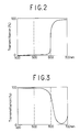
- Fig. 2 is a spectral transmittance curve of a dye for use in red color filter.
- Fig. 3 is a spectral transmittance curve of a blue dichroic dye measured when a monochromatic polarizing film containing the dye is overlapped by a neutral polarizing film with the polarization axes of the films at a right angle.
- Fig. 4 is a spectral transmittance curve of a dye for use in green color filter.
- Fig. 5 is a spectral transmittance curve of a red dichroic dye measured when a monochromatic polarizing film containing the dye is overlapped by a neutral polarizing film with the polarization axes of the films at a right angle.
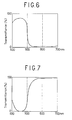
- Fig. 6 is a spectral transmittance curve of a dye for use in blue color filter.
- Fig. 7 is a spectral transmittance curve of a yellow dichroic dye measured when a monochromatic polarizing film containing the dye is overlapped by a neutral polarizing film with the polarization axes of the films at a right angle.
- the present color filter having a capability to polarize comprises, in combination, a dye having a spectral transmittance (“transmittance dye”), and a dichroic dye corresponding thereto.
- polarizing filter comprises, in combination, a dye having a spectral transmittance (“transmittance dye”), and a dichroic dye corresponding thereto.
- polarizing filter is a single polarizing filter which is a combination of a polarizing yellow dichroic dye and a blue transmittance dye or a combination of a polarizing red dichroic dye and a green transmittance dye or a combination of a polarizing blue dichroic dye and a red transmittance dye.
- a preferred embodiment of the present invention is a single film having two functions, i.e.-, a color filter function and a polarizing ability.
- a color filter may give excellent light transmittance, lead to no reduction in polarizing light due to light scattering, and provide excellent workability in assembling of a liquid crystal projection Tv set because it is a single film; thus, it is an excellent material for use in the liquid crystal projection TV set.
- the transmittance dye may comprise one or more of cyanine type dyes, phthalocyanine type dyes, anthraquinone type dyes, azo type dyes, quinophthalone type dyes, perylene type dyes and cumarin type dyes.
- cyanine type dyes phthalocyanine type dyes
- anthraquinone type dyes azo type dyes
- quinophthalone type dyes perylene type dyes and cumarin type dyes.
- the dye shows, in the visible light region of 400-700 nm, the following wavelength characteristic and a dichroic ratio at the maximum absorption wavelength, of 5 or less, preferably 2 or less. That is, said dye is preferably:
- the dichroic dye used in the present invention may comprise one or more of anthraquinone type dyes, azo type dyes, quinophthalone type dyes, perylene type dyes and cumarin type dyes.
- the dichroic dye is such that when a monochromatic polarizing film containing the dye is overlapped with a neutral polarizing film, the polarization axes being at a right angle, the dye shows, in the visible light region of 400-700 nm, the following wavelength characteristic and a dichroic ratio at the maximum absorption wavelength, of 6 or more, preferably 10 or more. That is, said dye is preferably:
- Suitable combinations of a transmittance dye and a dichroic dye for use in a polarizing color filter embodying the invention include:
- a polarizing color filter employing the above combination (1), i.e., a combination of a red dye suitable for a color filter and a blue dichroic dye.
- the red color filter and the neutral polarizing film-1 are replaced by a single color filter having a polarizing ability, employing the combination (1) and when a light from a light source is passed through the color filter and the resulting polarized light of 600-700 nm is transmitted through the liquid crystal cell and the neutral polarizing film-2, a red image is formed on the screen; while, when the light is absorbed, no image is formed on the screen.
- a color filter employing the combination (2) i.e., a combination of a green dye suitable for a color filter and a red dichroic dye
- a color filter employing the combination (3) i.e., a combination of a blue dye suitable for a color filter and a yellow dichroic dye.
- the process of the present invention for producing a polarizing color filter includes various processes such as the following:
- the resin used in the color filter may be any resin as long as it is transparent and is easily oriented by monoaxial stretching. It includes polyethylene terephthalate (PET), polybutylene terephthalate (PBT), polyethylene naphthalate (PEN), and polyvinyl alcohol (PVA).
- PET polyethylene terephthalate
- PBT polybutylene terephthalate
- PEN polyethylene naphthalate
- PVA polyvinyl alcohol
- the first process for producing the present color filter which comprises coating the transmittance dye or a mixture thereof onto the monochromatic polarizing film, may be conducted as follows:
- the production of the monochromatic polarizing film may be conducted by the following processes, as described in, for example, Japanese Patent Application Kokai (Laid-open) Nos. 270664/1987 (USP 5,059,356) and 275163/1987 (USP 4,824,882):
- the above-produced polarizing film may be coated with a dye as follows:
- a dye for a color filter may be dissolved in a single or mixed solvent selected from aliphatic hydrocarbons such as octane, hexane, cyclohexane, dimethylcyclohexane and ethylcyclohexane, aromatic hydrocarbons such as toluene and xylene, halogen-containing solvents such as chloroform and trichloroethane, ethers such as tetrahydrofuran and dioxane, alcohols such as ethanol, methanol, ethylene glycol methyl ether (trade name: METHYL CELLOSOLVE), ethylene glycol ethyl ether (trade name: ETHYL CELLOSOLVE), ethylene glycol propyl ether (trade name: PROPYL CELLOSOLVE), ethylene glycol butyl ether (trade name: BUTYL CELLOSOLVE) and
- the second process for producing the present color filter which comprises mixing a substrate resin, a dichroic dye and a transmittance dye and then subjecting the mixture to stretching, is suitable conducted as follows: Two dyes and a resin are mixed at a temperature higher than the melting point of the resin; the mixture is subjected to melt extrusion to prepare a material film; and the film is stretched by the method mentioned in the first process. Alternatively, two dyes and a resin are dissolved in a solvent; a cast film is prepared from the solution; and the film is stretched by the method mentioned in the first process. Thus, a polarizing color filter is obtained.
- the dyeing is conducted, for example, by the following methods:
- the dyed film may be monoaxially stretched from 3- to 10-fold at the glass transition temperature (Tg) of the transparent film, whereby a polarizing color filter is obtained.
- the stretching may be dry or wet stretching. As necessary, thermofixing by annealing may be conducted. In the stretching of a PVA film, a boric acid treatment is applied during or after the stretching.
- the fourth process for producing a color filter which comprises dyeing a monoaxially stretched film, is conducted as follows: A transparent film such as PVA film, PET film or the like is monoaxially stretched from 3- to 10-fold; then, the stretched film is dyed, suitable by one of the following methods:
- Each solvent used in the above dyeing methods is preferably water or ethylene glycol.
- Each dye may be dissolved completely or dispersed in each solvent. During the dyeing, there may be added as necessary 0.001-10% of a nonionic or anionic surfactant and 0.001-10% of Glauber's salt or a salt.
- trasmittance dye means not only a single substance but also a mixture of two or more substances.
- a red polarizing film (PET type, a product of Mitsui Toatsu Chemicals, Inc.) was coated, by spin coating (1,500 rpm), with a solution of 1 g of a green dye suitable for a color filter (a transmittance dye), represented by formula (1) and 2 g of a yellow dye for a color filter (a transmittance dye), represented by formula (2), dissolved in 200 g of toluene, whereby a green color filter having a polarizability was produced. Pairs of the thus-produced color filters were overlapped with each other so that the respective polarization axes were parallel or at a right angle to each other. The resulting two laminates were measured for absorption spectra simultaneously.
- the laminate in which the two color filters had their polarization axes in parallel gave a high transmittance at 520-570 nm.
- the color filter had excellent performance as a green filter.
- the color filter exhibited a large dichroic ratio at 520-570 nm and consequently, it had a high polarizing ability.
- a blue polarizing film (PET type, a product of Nitto Electric Industrial Co., Ltd.) was coated, by spin coating (2,000 rpm), with a solution of 1 g of a red dye for a color filter, represented by formula (3) and 0.5 g of a yellow dye for a color filter, represented by formula (2), dissolved in 200 g of cyclohexanone, whereby a red color polarising filter was produced. Pairs of the thus-produced color filters were overlapped to each other with their polarization axes either parallel or at a right angle to each other. The resulting laminates were measured for absorption spectra simultaneously.
- PET type a product of Nitto Electric Industrial Co., Ltd.
- the color filter had excellent performance as a red filter.
- the color filter exhibited a large dichroic ratio at 620-700 nm and consequently, it had a high polarizing power.
- a PVA film was dyed for 5 minutes in a dyeing bath of 2 g of a 1:1 mixture of two dichroic dyes, i.e., C.I. Direct Yellow 12 and C.I. Direct Orange 39 (produced by Nippon Kayaku Co., Ltd., trade name: KAYARUS SUPRA ORANGE 2GL) dissolved in 1 liter of water.
- the dyed film was stretched 4-fold and dipped in a 5% aqueous boric acid solution for 3 minutes.
- the resulting film was air-dried at room temperature.
- TAC triacetylcellulose
- the thus-produced yellow polarizing film was coated, by spin coating (1,800 rpm), with a solution of 1 g of a blue dye for a color filter, represented by formula (4) and 0.5 g of a blue dye for a color filter, represented by formula (5), dissolved in 200 g of toluene, whereby a blue color polarizing filter was produced. Pairs of the thus-produced color filters were overlapped to each other so that the respective polarization axes were parallel or at a right angle to each other. The resulting laminates were measured for absorption spectra simultaneously. The laminate in which the two color filters had their polarization axes in parallel, gave a high transmittance at 420-480 nm. Thus, the color filter had excellent performance as a blue filter. Further, the color filter exhibited a large dichroic ratio at 420-480 nm and consequently, it had a high polarizing ability.
- the resulting two laminates were measured for absorption spectra simultaneously.
- the color filter had excellent performance as a green filter.
- the color filter exhibited a large dichroic ratio at 52C-570 nm and consequently, it had a high polarizing ability.
- the color filter when allowed to stand for 500 hours under the conditions of 80°C and 90% relative humidity, gave substantially no change in color and substantially no reduction in polarizing ability.
- Pairs of the thus-produced color filters were overlapped to each other so that the respective polarization axes became parallel or at a right angle to each other.
- the resulting two laminates were measured for absorption spectra simultaneously.
- the color filter had excellent performance as a red filter.
- the color filter exhibited a large dichroic ratio at 620-700 nm and consequently, it had a high polarizing ability.
- the color filter when allowed to stand for 500 hours under the conditions of 80°C and 90% relative humidity, gave substantially no change in color and substantially no reduction in polarizing ability.
- the resulting two laminates were measured for absorption spectrums simultaneously.
- the color filter had excellent performance as a blue filter.
- the color filter exhibited a large dichroic ratio at 420-480 nm and consequently, it had a high polarizing ability.
- the color filter when allowed to stand for 500 hours under the conditions of 80°C and 90% relative humidity, gave substantially no change in color and substantially no reduction in polarizability.
- a PVA film was dyed for 5 minutes in a dyeing bath of 2 g of a 1:1:3 mixture of two dyes for a color filter, i.e., C.I. Reactive Blue 19 and C.I. Reactive Yellow 3 and a dichroic dye, i.e., C.I. Direct Red 81 dissolved in 1 liter of water.
- the dyed film was stretched 4-fold and dipped in a 5% aqueous boric acid solution for 3 minutes.
- the resulting film was air-dried at room temperature.
- TAC triacetylcellulose
- Pairs of the thus-produced color filters were overlapped to each other so that the respective polarization axes became parallel or at a right angle to each other.
- the resulting two laminates were measured for absorption spectra simultaneously.
- the color filter had excellent performance as a green filter.
- the color filter exhibited a large dichroic ratio at 520-570 nm and consequently, it had a high polarizing ability.
- a PVA film was dyed for 5 minutes in a dyeing bath of 2 g of a 2:1:1:1 mixture of two dyes for a color filter, i.e., C.I. Reactive Red 6 and C.I. Reactive Yellow 17 and two dichroic dyes, i.e., C.I. Direct Blue 168 and C.I. Direct Blue 202 dissolved in 1 liter of water.
- the dyed film was stretched 4-fold and dipped in a 5% aqueous boric acid solution for 3 minutes.
- the resulting film was air-dried at room temperature.
- stretched and dried PVA film were overlapped triacetylcellulose (TAC) films as a protective film.
- TAC triacetylcellulose
- Pairs of the thus-produced color filters were overlapped to each other so that the respective polarization axes became parallel or at a right angle to each other.
- the resulting two laminates were measured for absorption spectra simultaneously.
- the color filter had excellent performance as a red filter.
- the color filter exhibited a large dichroic ratio at 620-700 nm and consequently, it had a high polarizing ability.
- a PVA film was dyed for 5 minutes in a dyeing bath of 2 g of a 1:2:1:2 mixture of two dyes for a color filter, i.e., C.I. Reactive Violet 2 and C.I. Reactive Blue 19 and two dichroic dyes, i.e., C.I. Direct Yellow 12 and C.I. Direct Orange 12 dissolved in 1 liter of water.
- the dyed film was stretched 4-fold and dipped in a 5% aqueous boric acid solution for 3 minutes.
- the resulting film was air-dried at room temperature.
- TAC triacetylcellulose
- Pairs of the thus-produced color filters were overlapped to each other so that the respective polarization axes became parallel or at a right angle to each other.
- the resulting two laminates were measured for absorption spectra simultaneously.
- the color filter had excellent performance as a blue filter.
- the color filter exhibited a large dichroic ratio at 420-480 nm and consequently, it had a high polarizing ability.
- a PVA film was stretched 4-fold and then dyed for 5 minutes in a dyeing bath of 2 g of a 1:1:3 mixture of two dyes for a color filter, i.e., C.I. Reactive Blue 19 and C.I. Reactive Yellow 3 and a dichroic dye, i.e., C.I. Direct Red 81 dissolved in 1 liter of water.
- the dyed film was dipped in a 5% aqueous boric acid solution for 3 minutes.
- the resulting film was air-dried at room temperature.
- TAC triacetylcellulose
- Pairs of the thus-produced color filters were overlapped to each other so that the respective polarization axes became parallel or at a right angle to each other.
- the resulting two laminates were measured for absorption spectra simultaneously.
- the color filter had excellent performance as a blue filter.
- the color filter exhibited a large dichroic ratio at 520-570 nm and consequently, it had a high polarizing ability.
- a PVA film was stretched 4-fold and then dyed for 5 minutes in a dyeing bath of 2 g of a 2:1:1:1 mixture of two dyes for a color filter, i.e., C.I. Reactive Red 6 and C.I. Reactive Yellow 17 and two dichroic dyes, i.e., C.I. Direct Blue 168 and C.I. Direct Blue 202 dissolved in 1 liter of water.
- the dyed film was dipped in a 5% aqueous boric acid solution for 3 minutes. The resulting film was air-dried at room temperature.
- TAC triacetylcellulose
- Pairs of the thus-produced color filters were overlapped to each other so that the respective polarization axes became parallel or at a right angle to each other.
- the resulting two laminates were measured for absorption spectra simultaneously.
- the color filter had excellent performance as a red filter.
- the color filter exhibited a large dichroic ratio at 620-700 nm and consequently, it had a high polarizing ability.
- a PVA film was stretched 4-fold and then dyed for 5 minutes in a dyeing bath of 2 g of a 1:2:1:2 mixture of two dyes for a color filter, i.e., C.I. Reactive Violet 2 and C.I. Reactive Blue 19 and two dichroic dyes, i.e., C.I. Direct Yellow 12 and C.I. Direct Orange 12 dissolved in 1 liter of water.
- the dyed film was dipped in a 5% aqueous boric acid solution for 3 minutes. The resulting film was air-dried at room temperature.
- TAC triacetylcellulose
- Pairs of the thus-produced color filters were overlapped to each other so that the respective polarization axes became parallel or at a right angle to each other.
- the resulting two laminates were measured for absorption spectra simultaneously.
- the color filter had excellent performance as a blue filter.
- the color filter exhibited a large dichroic ratio at 420-480 nm and consequently, it had a high polarizing ability.
Description


Claims (6)
- A color filter having a capability to polarize light, which comprises a dye having a spectral transmittance subsequently referred to as "transmittance dye", a dichroic dye having a capability to polarize light, and a base resin, wherein the combination of the transmittance dye and the dichroic dye is such that (1) the transmittance dye is red and the dichroic dye is blue for a red color polarizing filter, (2) the transmittance dye is green and the dichroic dye is red for a green color polarizing filter, or (3) the transmittance dye is blue and the dichroic dye is yellow for a blue color polarizing filter.
- The color filter according to claim 1, wherein at least one of the transmittance dye and the dichroic dye is contained in the base resin.
- A process for producing a color filter having a capability to polarize light, which comprises coating and fixing a dye having a spectral transmittance subsequently referred to as "transmittance dye" on a monochromatic polarizing film comprising a dichroic dye, wherein the combination of the transmittance dye and the dichroic dye is such that (1) the transmittance dye is red and the dichroic dye is blue for a red color polarizing filter, (2) the transmittance dye is green and the dichroic dye is red for a green color polarizing filter or (3) the transmittance dye is blue and the dichroic dye is yellow for a blue color polarizing filter.
- A process for producing a color filter having a capability to polarize light, which comprises mixing a dye having a spectral transmittance subsequently referred to as "transmittance dye", a dichroic dye, and a transparent resin, subjecting the mixture to melt extrusion to obtain a film, and subjecting the film to monoaxial stretching; wherein the combination of the transmittance dye and the dichroic dye is such that (1) the transmittance dye is red and the dichroic dye is blue for a red color polarizing filter, (2) the transmittance dye is green and the dichroic dye is red for a green color polarizing filter, or (3) the transmittance dye is blue and the dichroic dye is yellow for a blue color polarizing filter.
- A process for producing a color filter having a capability to polarize light, which comprises dyeing a transparent film with a dye having a spectral transmittance subsequently referred to as "transmittance dye" and a dichroic dye, and subjecting the dyed film to monoaxial stretching; wherein the combination of the transmittance dye and the dichroic dye is such that (1) the transmittance dye is red and the dichroic dye is blue for a red color polarizing filter, (2) the transmittance dye is green and the dichroic dye is red for a green color polarizing filter, or (3) the transmittance dye is blue and the dichroic dye is yellow for a blue color polarizing filter.
- A process for producing a color filter having a capability to polarize light, which comprises dyeing a transparent monoaxially stretched film with a dye having a spectral transmittance subsequently referred to as "transmittance dye" and a dichroic dye, wherein the combination of the transmittance dye and the dichroic dye is such that (1) the transmittance dye is red and the dichroic dye is blue for a red color polarizing filter, (2) the transmittance dye is green and the dichroic dye is red for a green color polarizing filter, or (3) the transmittance dye is blue and the dichroic dye is yellow for a blue color polarizing filter.
Applications Claiming Priority (2)
| Application Number | Priority Date | Filing Date | Title |
|---|---|---|---|
| JP34633492 | 1992-12-25 | ||
| JP346334/92 | 1992-12-25 |
Publications (2)
| Publication Number | Publication Date |
|---|---|
| EP0605191A1 EP0605191A1 (en) | 1994-07-06 |
| EP0605191B1 true EP0605191B1 (en) | 1998-06-17 |
Family
ID=18382712
Family Applications (1)
| Application Number | Title | Priority Date | Filing Date |
|---|---|---|---|
| EP93310433A Expired - Lifetime EP0605191B1 (en) | 1992-12-25 | 1993-12-22 | Polarizing color filter |
Country Status (3)
| Country | Link |
|---|---|
| US (1) | US5751483A (en) |
| EP (1) | EP0605191B1 (en) |
| DE (1) | DE69319215T2 (en) |
Cited By (1)
| Publication number | Priority date | Publication date | Assignee | Title |
|---|---|---|---|---|
| TWI631152B (en) * | 2012-08-21 | 2018-08-01 | 三菱瓦斯化學股份有限公司 | Fading film, and polarizing film, and the manufacturing method thereof |
Families Citing this family (17)
| Publication number | Priority date | Publication date | Assignee | Title |
|---|---|---|---|---|
| US6414731B2 (en) * | 1990-11-30 | 2002-07-02 | Sun Microsystems, Inc. | Low cost virtual reality system |
| JPH10170905A (en) * | 1996-12-09 | 1998-06-26 | Alps Electric Co Ltd | Color polarization filter for reflection and reflection-type color liquid crystal display device using the filter |
| US20020005509A1 (en) * | 1999-01-21 | 2002-01-17 | Chia-Chi Teng | Dye combinations for image enhancement filters for color video displays |
| US20010005281A1 (en) * | 1999-08-08 | 2001-06-28 | Caroline Yu | Optical system for increasing contrast of object viewed through it |
| US6538714B1 (en) * | 1999-10-25 | 2003-03-25 | 3M Innovative Properties Company | Dual color guest-host polarizers and devices containing guest-host polarizers |
| US6574044B1 (en) * | 1999-10-25 | 2003-06-03 | 3M Innovative Properties Company | Polarizer constructions and display devices exhibiting unique color effects |
| US6597504B2 (en) | 2000-12-29 | 2003-07-22 | Honeywell International Inc. | Optical devices employing beam folding with polarizing splitters |
| US6642977B2 (en) | 2001-06-20 | 2003-11-04 | 3M Innovative Properties Company | Liquid crystal displays with repositionable front polarizers |
| US20030017856A1 (en) * | 2001-06-20 | 2003-01-23 | 3M Innovative Properties Company | Method for altering the appearance of liquid crystal displays using exchangable front polarizers |
| AU2003263520A1 (en) * | 2002-10-14 | 2004-05-04 | Koninklijke Philips Electronics N.V. | Color filter and liquid crystal display device comprising such filter |
| TWI245130B (en) * | 2003-05-02 | 2005-12-11 | Optimax Tech Corp | Color compensational layer's structure and manufacturing method thereof |
| ES2718461T3 (en) * | 2007-02-28 | 2019-07-02 | Corning Inc | Polarizing articles of light and method of making them |
| KR102216829B1 (en) | 2013-01-25 | 2021-02-17 | 미츠비시 가스 가가쿠 가부시키가이샤 | Colored low-polarization film, colored low-polarization sheet, lens and method for manufacturing same |
| JP6619619B2 (en) * | 2015-11-04 | 2019-12-11 | 日東電工株式会社 | Polarizer, polarizing plate, and method for producing polarizer |
| KR102643464B1 (en) * | 2016-02-22 | 2024-03-05 | 삼성전자주식회사 | Color polarizing film and antireflective film and display device |
| EP3485302A1 (en) * | 2016-07-15 | 2019-05-22 | Essilor International | Polarized films with specific light filters |
| KR102158811B1 (en) * | 2018-07-03 | 2020-09-22 | 주식회사 엘엠에스 | Optical disc for fingerprint recognition sensor and optical filter including the same |
Family Cites Families (18)
| Publication number | Priority date | Publication date | Assignee | Title |
|---|---|---|---|---|
| US4304683A (en) * | 1979-03-16 | 1981-12-08 | Mitsui Toatsu Chemicals, Inc. | Composition for liquid crystal color display element |
| US4360447A (en) * | 1979-03-16 | 1982-11-23 | Mitsui Toatsu Chemicals, Inc. | Composition for liquid crystal color display elements |
| JPS5763377A (en) * | 1980-10-03 | 1982-04-16 | Mitsui Toatsu Chem Inc | Liquid crystal composition for color display |
| US4466704A (en) * | 1981-07-20 | 1984-08-21 | Polaroid Corporation | Patterned polarizer having differently dyed areas |
| JPS59172610A (en) * | 1983-03-22 | 1984-09-29 | Nitto Electric Ind Co Ltd | Manufacture of polarizing film |
| JPS59219719A (en) * | 1983-05-27 | 1984-12-11 | Seiko Instr & Electronics Ltd | Display device of color liquid crystal |
| US4541691A (en) * | 1983-12-27 | 1985-09-17 | Tektronix, Inc. | Electro-optic switching system using circularly polarized light |
| US4611889A (en) * | 1984-04-04 | 1986-09-16 | Tektronix, Inc. | Field sequential liquid crystal display with enhanced brightness |
| JPS6187757A (en) * | 1984-10-05 | 1986-05-06 | Mitsui Toatsu Chem Inc | Coloring matter and polarizing film obtained by using the same |
| US5286418A (en) * | 1984-10-05 | 1994-02-15 | Mitsui Toatsu Chemicals, Incorporated | Polarizing film |
| CA1269555A (en) * | 1984-11-16 | 1990-05-29 | Sumitomo Chemical Company, Limited | Light-polarizing film |
| JPS6254201A (en) * | 1985-09-03 | 1987-03-09 | Mitsubishi Chem Ind Ltd | Polarizing film and its production |
| US4770500A (en) * | 1986-06-10 | 1988-09-13 | Kaiser Aerospace And Electronics Corporation | Method and apparatus for multi color display |
| US4749259A (en) * | 1987-05-15 | 1988-06-07 | Hughes Aircraft Company | Liquid crystal image projection with multicolor prepolarizing system |
| JP2663440B2 (en) * | 1987-06-12 | 1997-10-15 | 三菱瓦斯化学株式会社 | Manufacturing method of polarizing film |
| US4991941A (en) * | 1988-06-13 | 1991-02-12 | Kaiser Aerospace & Electronics Corporation | Method and apparatus for multi-color display |
| JPH0232303A (en) * | 1988-07-21 | 1990-02-02 | Nippon Kayaku Co Ltd | Color polarizing film |
| JPH05127189A (en) * | 1991-11-07 | 1993-05-25 | Hitachi Ltd | Color display device |
-
1993
- 1993-12-22 DE DE69319215T patent/DE69319215T2/en not_active Expired - Fee Related
- 1993-12-22 EP EP93310433A patent/EP0605191B1/en not_active Expired - Lifetime
-
1995
- 1995-08-01 US US08/510,007 patent/US5751483A/en not_active Expired - Fee Related
Cited By (1)
| Publication number | Priority date | Publication date | Assignee | Title |
|---|---|---|---|---|
| TWI631152B (en) * | 2012-08-21 | 2018-08-01 | 三菱瓦斯化學股份有限公司 | Fading film, and polarizing film, and the manufacturing method thereof |
Also Published As
| Publication number | Publication date |
|---|---|
| US5751483A (en) | 1998-05-12 |
| EP0605191A1 (en) | 1994-07-06 |
| DE69319215T2 (en) | 1998-10-22 |
| DE69319215D1 (en) | 1998-07-23 |
Similar Documents
| Publication | Publication Date | Title |
|---|---|---|
| EP0605191B1 (en) | Polarizing color filter | |
| EP0777865B1 (en) | Film containing oriented dye, method of manufacturing the same, and polarizer and liquid crystal display unit utilizing the same | |
| KR100905144B1 (en) | Optical Device | |
| JP3174367B2 (en) | Laminated wave plate and circularly polarizing plate | |
| US20040008298A1 (en) | Photo-patterned light polarizing films | |
| US6337111B1 (en) | Optically anisotropic thin film and process for producing the same | |
| US6847420B2 (en) | Liquid crystal display with reflecting polarizer | |
| US20130280438A1 (en) | Method for producing polarizing film, and liquid crystal display device | |
| WO2018088558A1 (en) | Dye-based polarizing plate for infrared wavelength range | |
| JP2013164525A (en) | Laminate and application of the same | |
| US6404472B1 (en) | Film containing oriented dye, method of manufacturing the same, and polarizer and liquid crystal display unit utilizing the same | |
| WO2011065587A1 (en) | Va-mode liquid-crystal display device | |
| JP2001091736A (en) | Polarizing film and polarizing plate | |
| US20200292739A1 (en) | Image display apparatus and circularly polarizing plate to be used in the image display apparatus | |
| JPH06242318A (en) | Color filter having polarizing capability | |
| US20030112414A1 (en) | Contrast ratio improving method for liquid crystal projector | |
| JPH11281817A (en) | Polarizing film | |
| JP2001281452A (en) | Optical film, polarizing plate and liquid crystal display device | |
| CN1312509C (en) | Colour filter means having optical activity under the influence of a polarized light | |
| WO2020255653A1 (en) | Optical film set for image generation system | |
| KR101835924B1 (en) | Optical film and method for preparing the same | |
| KR102108558B1 (en) | Preparation Method for Substrate used in Optical Device | |
| WO2017135766A1 (en) | Polarizing plate | |
| WO2020255652A1 (en) | Set of optical film for image generation system | |
| WO2003025092A1 (en) | Liquid crystal display with reflecting polarizer |
Legal Events
| Date | Code | Title | Description |
|---|---|---|---|
| PUAI | Public reference made under article 153(3) epc to a published international application that has entered the european phase |
Free format text: ORIGINAL CODE: 0009012 |
|
| 17P | Request for examination filed |
Effective date: 19940111 |
|
| AK | Designated contracting states |
Kind code of ref document: A1 Designated state(s): DE FR GB |
|
| 17Q | First examination report despatched |
Effective date: 19960805 |
|
| GRAG | Despatch of communication of intention to grant |
Free format text: ORIGINAL CODE: EPIDOS AGRA |
|
| GRAG | Despatch of communication of intention to grant |
Free format text: ORIGINAL CODE: EPIDOS AGRA |
|
| GRAH | Despatch of communication of intention to grant a patent |
Free format text: ORIGINAL CODE: EPIDOS IGRA |
|
| GRAH | Despatch of communication of intention to grant a patent |
Free format text: ORIGINAL CODE: EPIDOS IGRA |
|
| GRAA | (expected) grant |
Free format text: ORIGINAL CODE: 0009210 |
|
| RAP1 | Party data changed (applicant data changed or rights of an application transferred) |
Owner name: MITSUI CHEMICALS, INC. |
|
| AK | Designated contracting states |
Kind code of ref document: B1 Designated state(s): DE FR GB |
|
| REF | Corresponds to: |
Ref document number: 69319215 Country of ref document: DE Date of ref document: 19980723 |
|
| ET | Fr: translation filed | ||
| PGFP | Annual fee paid to national office [announced via postgrant information from national office to epo] |
Ref country code: FR Payment date: 19981119 Year of fee payment: 6 |
|
| PGFP | Annual fee paid to national office [announced via postgrant information from national office to epo] |
Ref country code: GB Payment date: 19981211 Year of fee payment: 6 |
|
| PGFP | Annual fee paid to national office [announced via postgrant information from national office to epo] |
Ref country code: DE Payment date: 19981229 Year of fee payment: 6 |
|
| PLBE | No opposition filed within time limit |
Free format text: ORIGINAL CODE: 0009261 |
|
| STAA | Information on the status of an ep patent application or granted ep patent |
Free format text: STATUS: NO OPPOSITION FILED WITHIN TIME LIMIT |
|
| 26N | No opposition filed | ||
| PG25 | Lapsed in a contracting state [announced via postgrant information from national office to epo] |
Ref country code: GB Free format text: LAPSE BECAUSE OF NON-PAYMENT OF DUE FEES Effective date: 19991222 |
|
| GBPC | Gb: european patent ceased through non-payment of renewal fee |
Effective date: 19991222 |
|
| PG25 | Lapsed in a contracting state [announced via postgrant information from national office to epo] |
Ref country code: FR Free format text: LAPSE BECAUSE OF NON-PAYMENT OF DUE FEES Effective date: 20000831 |
|
| PG25 | Lapsed in a contracting state [announced via postgrant information from national office to epo] |
Ref country code: DE Free format text: LAPSE BECAUSE OF NON-PAYMENT OF DUE FEES Effective date: 20001003 |
|
| REG | Reference to a national code |
Ref country code: FR Ref legal event code: ST |