EP0606068B1 - Battery terminal - Google Patents
Battery terminal Download PDFInfo
- Publication number
- EP0606068B1 EP0606068B1 EP94100062A EP94100062A EP0606068B1 EP 0606068 B1 EP0606068 B1 EP 0606068B1 EP 94100062 A EP94100062 A EP 94100062A EP 94100062 A EP94100062 A EP 94100062A EP 0606068 B1 EP0606068 B1 EP 0606068B1
- Authority
- EP
- European Patent Office
- Prior art keywords
- clamping members
- post
- nut
- bolt
- battery
- Prior art date
- Legal status (The legal status is an assumption and is not a legal conclusion. Google has not performed a legal analysis and makes no representation as to the accuracy of the status listed.)
- Expired - Lifetime
Links
Images

Classifications
-
- H—ELECTRICITY
- H01—ELECTRIC ELEMENTS
- H01R—ELECTRICALLY-CONDUCTIVE CONNECTIONS; STRUCTURAL ASSOCIATIONS OF A PLURALITY OF MUTUALLY-INSULATED ELECTRICAL CONNECTING ELEMENTS; COUPLING DEVICES; CURRENT COLLECTORS
- H01R11/00—Individual connecting elements providing two or more spaced connecting locations for conductive members which are, or may be, thereby interconnected, e.g. end pieces for wires or cables supported by the wire or cable and having means for facilitating electrical connection to some other wire, terminal, or conductive member, blocks of binding posts
- H01R11/11—End pieces or tapping pieces for wires, supported by the wire and for facilitating electrical connection to some other wire, terminal or conductive member
- H01R11/28—End pieces consisting of a ferrule or sleeve
- H01R11/281—End pieces consisting of a ferrule or sleeve for connections to batteries
- H01R11/283—Bolt, screw or threaded ferrule parallel to the battery post
Definitions
- the present invention relates to a battery terminal mounted to the post of a motor vehicle battery, and particularly to a battery terminal that is clamped using a tightening tool by tightening a bolt from above to firmly clamp the battery terminal to the battery post.
- the main terminal 3 of a conventional battery terminal of this type is made by bending a flat metal plate in two around a curve 3a at one end of the resulting main terminal 3.
- the top and bottom parts of this main terminal 3 are roughly identical in shape, and the bend imparts a certain flexibility to the terminal.
- This main terminal 3 comprises a pair of top and bottom circular post fittings 3b, each of which is flat in the horizontal direction and both of which are fit over the battery post 2.
- a pair of right and left tightening members 3c which are similarly flat in the horizontal direction, are provided contiguous to the free open ends of the circular post fittings 3b.
- the cable connector 3d is provided at the other, closed, end of the circular post fittings 3b.
- a bearing washer 5 is placed at the outside of one of the tightening members 3c, and a bolt 6 is passed through the bearing washer 5 from the outside of the other tightening member 3c.
- a nut 7 is then threaded onto the bearing washer 5 end of the bolt 6 and tightened against the bearing washer 5 to tighten the right and left tightening members 3c, thus closing the free end of the circular post fittings 3b and firmly clamping the battery terminal to the battery post 2.
- this main terminal is manufactured by bending a single metal plate and the components are fairly complex bent shapes, a thick metal plate cannot be used.
- the mechanical strength of the terminal cannot, therefore, be set high, the torque applied to the bolt 6 to tighten the tightening members 3c is not consistent, and poor contact between the battery terminal and battery post 2 can result from the instability of the bolt clamping force.
- US-A-1 746 514 discloses a battery terminal according to the preamble of claim 1, in which the annular post fitting has a vertically oriented cylindrical shape, and first and second clamping members are contiguous to the open free ends of the post fitting.
- the clamping members have tapered sliding surfaces which cooperate with a tightening tool which is pressed against the clamping members by means of a vertically oriented bolt and nut assembly.
- the bolt is inserted between the clamping members from below so that its head abuts at the lower surfaces of the clamping members, and the nut is screwed onto the bolt and engages a top surface of the tightening tool.
- the required tightening torque can be made more consistent, and the bolt and nut assembly can be tightened from above and the vertical tightening force can be converted into a horizontal force to firmly clamp the post fitting to the battery post and assure positive terminal-post contact.
- the post fitting and the clamping members are formed as an integral piece which has a rather complex shape and cannot be manufactured by appropriately bending a metal plate.
- the thickness of the plate used to manufacture the main terminal can be increased in comparison to the prior art shown in Fig. 4, because the annular post fitting of the main terminal and the right and left clamping members contiguous to the free ends thereof are formed from a single vertically oriented plate and are shaped more simply than those of the prior art.
- the tightening torque of the bolt can also be stably applied because the mechanical strength of the main terminal can thus be increased.
- the right and left clamping members are shaped to provide sliding surfaces following the tapered surfaces of the tightening tool, the downward travel of the tightening tool caused by tightening the bolt is converted into movement closing the free ends of the post fitting contiguous to the clamping members, and the battery terminal can be positively clamped to the battery post.
- the battery terminal can be tightened from a position above the battery terminal, and the problems caused by tightening from the side do not occur as with the prior art shown in Fig. 4.
- claws projecting to the inside of the clamping members to hold the nut are simply formed by punching the clamping members.
- Jam walls preventing nut rotation are provided in the right and left clamping members of the main terminal.
- Plural vertical grooves are provided in the inside wall of the main terminal post fitting to enable the free ends of the post fitting to move smoothly in the opening and closing directions.
- the main terminal is formed from a thicker metal plate than that used in the conventional main terminal shown in Fig. 4..
- the typical plate thickness in a conventional terminal is 1.2 mm, a 2.0 mm thick plate is used in the present invention.
- a battery terminal 10 of the present invention comprises a main terminal 11, tightening tool 12, bolt 13, and nut 14.
- the main terminal 11 is a stud-type terminal formed by bending a single metal plate as shown in the figure, forming a cable connector 16, post fitting 17, and clamping members 18.
- the cable connector 16 is formed by bending a rectangular plate in two horizontally to form top and bottom members 16A and 16B, respectively, and bending the end of the top member 16A down against the bottom member 16B.
- the terminal to which the electrical cable is crimped (not shown in the figures) is secured by a nut (not shown in the figures) to a stud bolt 20 projecting from approximately the center of the top member 16A.
- the post fitting 17 is contiguous to the bottom member 16B of the cable connector 16, and is formed by bending a vertical metal strip perpendicular to the cable connector 16 into a ring shape to form a vertically oriented cylindrical shape.
- Plural vertical grooves 17a are formed at an even interval in the inside circumference wall of the post fitting 17.
- the side of the post fitting 17 opposite the cable connector 16 is open, forming two free ends.
- the clamping members 18 are a pair of right and left clamping members 18A and 18B contiguous to the free ends of the post fitting 17 with a gap S between the clamping members 18A and 18B.
- the right and left clamping members 18A and 18B are connected to the free ends of the vertically oriented post fitting 17, they are formed from similarly vertically oriented metal bands.
- the right and left clamping members 18A and 18B have sliding surfaces 22A and 22B, respectively, sloping down to the outside from the top thereof.
- the bottom end of each sliding surface 22A or 22B is bent horizontally back to the inside forming flats 23A or 23B.
- the inside end of each flat 23A or 23B bends vertically down to form a jam wall 24A or 24B for preventing the rotation of nut 14.
- Claws 25A and 25B projecting into the clamping members 18 are also formed by punching the clamping members 18 in at approximately the center of the sliding surfaces 22A and 22B.
- the tightening tool 12 is an essentially inverted U-shaped member with a top 12a and two sides 12b and 12c, and a bolt hole 27 in the center of the top 12a. Cut-outs 28 and 29 open to the bottom are also provided at the center of the two sides 12b and 12c projecting down from the edges of the top 12a.
- a taper 28a and 28b in side 12b and a taper 29a and 29b (29a not shown in the figures) in side 12c are formed such that they are wider at the bottom than the top and match the slope of the right and left clamping members 18A and 18B of the main terminal 11.
- Claws 30a, 30b, 31a and 31b (31a not shown in the figures) projecting to the inside of the cut-outs 28 and 29 are formed at the bottom ends of the tapers 28a, 28b, 29a and 29b.
- the tightening tool 12 is fit over the clamping members 18A and 18B of the main terminal 11 before the battery terminal 10 is mounted to the battery post 2 (shown in Fig. 4).
- the square nut 14 is then placed between the clamping members 18A and 18B, the bolt 13 is passed through the bolt hole 27 of the tightening tool 12, and is partially threaded into the nut 14 to present a semi-locked state of the battery terminal 10.
- the tapers 28a - 29b of tightening tool 12 can slide against the sliding surfaces 22A and 22B of the main terminal 11, and the bottom ends of the sliding surfaces 22A and 22B contact the claws 30a - 31b of the tightening tool 12.
- the top of the nut 14 is also against the bottom end of the claws 25A and 25B projecting to the inside of the clamping members 18A and 18B.
- the sides of the nut 14 are also held by the jam walls 24A and 24B of the main terminal 11 so that the nut 14 will not turn when the bolt 13 is tightened.
- the battery terminal 10 is first assembled in the semi-locked state as described above, and is fit down onto the battery post 2. Note that the main terminal 11 can be fit easily to the battery post 2 because the free ends of the main terminal 11 post fitting 17 are open.
- An impact wrench or similar tool is then fit to the bolt 13 head, and the bolt 13 is tightened.
- the post fitting 17 is thus clamped against the outside circumference of the battery post 2, and the battery terminal 10 is clamped in positive contact to the battery post 2.
- the thickness of the main terminal 11 can thus be increased in a battery terminal 10 according to the present invention because the post fitting 17 and clamping members 18A, 18B of the main terminal are formed from a single vertically oriented metal band and are extremely simple in shape.
- the plate thickness in this embodiment is approximately 2.0 mm, approximately 0.8 mm thicker than in a conventional battery terminal. This also makes it possible to increase the mechanical strength of the battery terminal 10.
- the battery terminal can also be firmly clamped by tightening a bolt from above because the vertical movement of the tightening tool 12 created by tightening the bolt 13 is converted by means of the tightening tool 12 tapers 28a - 29b and the main terminal 11 sliding surfaces 22A and 22B to the horizontal movement of the free ends of the post fitting 17.
- the post fitting and right and left clamping members are formed from a single vertically oriented metal band in a battery terminal according to the present invention, the shape of the main terminal can be simplified, and the thickness of the metal plate forming the main terminal can be increased as a result. It is thereby possible to increase the mechanical strength of the main terminal, and to prevent deformation of the clamping members when the bolt is tightened.
- the clamping members are bent and sliding surfaces corresponding to the shape of the tightening tool tapers are provided, the downward movement of the tightening tool caused by bolt tightening can be converted by the tightening tool tapers to an inward horizontal movement of the post fitting free ends contiguous to the clamping members.
- the bolt can thus be tightened from above, and the problems associated with tightening the clamping bolt from the side can be eliminated.
Description
- The present invention relates to a battery terminal mounted to the post of a motor vehicle battery, and particularly to a battery terminal that is clamped using a tightening tool by tightening a bolt from above to firmly clamp the battery terminal to the battery post.
- As shown in Fig. 4, the
main terminal 3 of a conventional battery terminal of this type is made by bending a flat metal plate in two around acurve 3a at one end of the resultingmain terminal 3. The top and bottom parts of thismain terminal 3 are roughly identical in shape, and the bend imparts a certain flexibility to the terminal. - This
main terminal 3 comprises a pair of top and bottomcircular post fittings 3b, each of which is flat in the horizontal direction and both of which are fit over thebattery post 2. A pair of right and left tighteningmembers 3c, which are similarly flat in the horizontal direction, are provided contiguous to the free open ends of thecircular post fittings 3b. Thecable connector 3d is provided at the other, closed, end of thecircular post fittings 3b. - A bearing washer 5 is placed at the outside of one of the tightening
members 3c, and abolt 6 is passed through the bearing washer 5 from the outside of the other tighteningmember 3c. A nut 7 is then threaded onto the bearing washer 5 end of thebolt 6 and tightened against the bearing washer 5 to tighten the right and left tighteningmembers 3c, thus closing the free end of thecircular post fittings 3b and firmly clamping the battery terminal to thebattery post 2. - Because this main terminal is manufactured by bending a single metal plate and the components are fairly complex bent shapes, a thick metal plate cannot be used. The mechanical strength of the terminal cannot, therefore, be set high, the torque applied to the
bolt 6 to tighten the tighteningmembers 3c is not consistent, and poor contact between the battery terminal andbattery post 2 can result from the instability of the bolt clamping force. - In addition, the engine rooms of recent vehicles are crowded with a growing number of components installed in a confined space. This makes it difficult to adequately tighten the terminal fitting by applying a horizontal force because of interference by other engine room components with the tools. It is even possible for the impact wrench to contact the negative terminal while tightening the positive terminal fitting, causing an electrical short which, in a worst-case scenario, could cause an engine room fire.
- US-A-1 746 514 discloses a battery terminal according to the preamble of claim 1, in which the annular post fitting has a vertically oriented cylindrical shape, and first and second clamping members are contiguous to the open free ends of the post fitting. The clamping members have tapered sliding surfaces which cooperate with a tightening tool which is pressed against the clamping members by means of a vertically oriented bolt and nut assembly. The bolt is inserted between the clamping members from below so that its head abuts at the lower surfaces of the clamping members, and the nut is screwed onto the bolt and engages a top surface of the tightening tool. Thus, the required tightening torque can be made more consistent, and the bolt and nut assembly can be tightened from above and the vertical tightening force can be converted into a horizontal force to firmly clamp the post fitting to the battery post and assure positive terminal-post contact.
- However, in this known battery terminal the post fitting and the clamping members are formed as an integral piece which has a rather complex shape and cannot be manufactured by appropriately bending a metal plate.
- It is an object of the present invention to provide a battery terminal in which the post fitting and the clamping members can simply be formed by bending a metal band and which nevertheless has a high mechanical strength.
- This object is achieved with the features indicated in claim 1.
- The thickness of the plate used to manufacture the main terminal can be increased in comparison to the prior art shown in Fig. 4, because the annular post fitting of the main terminal and the right and left clamping members contiguous to the free ends thereof are formed from a single vertically oriented plate and are shaped more simply than those of the prior art. The tightening torque of the bolt can also be stably applied because the mechanical strength of the main terminal can thus be increased.
- In addition, because the right and left clamping members are shaped to provide sliding surfaces following the tapered surfaces of the tightening tool, the downward travel of the tightening tool caused by tightening the bolt is converted into movement closing the free ends of the post fitting contiguous to the clamping members, and the battery terminal can be positively clamped to the battery post. In other words, the battery terminal can be tightened from a position above the battery terminal, and the problems caused by tightening from the side do not occur as with the prior art shown in Fig. 4.
- In addition, claws projecting to the inside of the clamping members to hold the nut are simply formed by punching the clamping members.
- Useful details of the invention are indicated in the dependent claims.
- Jam walls preventing nut rotation are provided in the right and left clamping members of the main terminal.
- Plural vertical grooves are provided in the inside wall of the main terminal post fitting to enable the free ends of the post fitting to move smoothly in the opening and closing directions.
- In addition, the main terminal is formed from a thicker metal plate than that used in the conventional main terminal shown in Fig. 4.. For example, while the typical plate thickness in a conventional terminal is 1.2 mm, a 2.0 mm thick plate is used in the present invention.
- The present invention will become more fully understood from the detailed description given below and the accompanying diagrams wherein:
- Fig. 1 is a perspective view of the disassembled parts of a battery terminal according to the present invention,
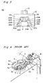
- Fig. 2 is a front view showing the semi-locked position of the battery terminal,
- Fig. 3 is a front view showing the battery terminal when clamped, and
- Fig. 4 is a perspective view of a conventional battery terminal.
- Referring to Figs. 1 and 2, a
battery terminal 10 of the present invention comprises amain terminal 11, tighteningtool 12,bolt 13, andnut 14. - The
main terminal 11 is a stud-type terminal formed by bending a single metal plate as shown in the figure, forming acable connector 16, post fitting 17, and clampingmembers 18. - The
cable connector 16 is formed by bending a rectangular plate in two horizontally to form top andbottom members top member 16A down against thebottom member 16B. The terminal to which the electrical cable is crimped (not shown in the figures) is secured by a nut (not shown in the figures) to astud bolt 20 projecting from approximately the center of thetop member 16A. - The post fitting 17 is contiguous to the
bottom member 16B of thecable connector 16, and is formed by bending a vertical metal strip perpendicular to thecable connector 16 into a ring shape to form a vertically oriented cylindrical shape. Pluralvertical grooves 17a are formed at an even interval in the inside circumference wall of the post fitting 17. The side of the post fitting 17 opposite thecable connector 16 is open, forming two free ends. - The
clamping members 18 are a pair of right and left clampingmembers clamping members - Because the right and left clamping
members members surfaces surface inside forming flats jam wall nut 14. -
Claws clamping members 18 are also formed by punching theclamping members 18 in at approximately the center of the slidingsurfaces - The tightening
tool 12 is an essentially inverted U-shaped member with a top 12a and twosides bolt hole 27 in the center of thetop 12a. Cut-outs sides top 12a. - A
taper side 12b and ataper 29a and 29b (29a not shown in the figures) inside 12c are formed such that they are wider at the bottom than the top and match the slope of the right and left clampingmembers main terminal 11.Claws outs tapers - As shown in Fig. 2, the
tightening tool 12 is fit over theclamping members main terminal 11 before thebattery terminal 10 is mounted to the battery post 2 (shown in Fig. 4). Thesquare nut 14 is then placed between theclamping members bolt 13 is passed through thebolt hole 27 of thetightening tool 12, and is partially threaded into thenut 14 to present a semi-locked state of thebattery terminal 10. - In this position, the
tapers 28a - 29b of tighteningtool 12 can slide against thesliding surfaces main terminal 11, and the bottom ends of thesliding surfaces claws 30a - 31b of thetightening tool 12. - The top of the
nut 14 is also against the bottom end of theclaws clamping members nut 14 are also held by thejam walls main terminal 11 so that thenut 14 will not turn when thebolt 13 is tightened. - The operation for mounting the
battery terminal 10 to thebattery post 2 in this semi-locked state is described below. - The
battery terminal 10 is first assembled in the semi-locked state as described above, and is fit down onto thebattery post 2. Note that themain terminal 11 can be fit easily to thebattery post 2 because the free ends of themain terminal 11 post fitting 17 are open. - An impact wrench or similar tool is then fit to the
bolt 13 head, and thebolt 13 is tightened. - As the
bolt 13 is tightened, thebolt 13 and tighteningtool 12 both descend. This downward movement of the tighteningtool 12 is converted by the movement of thetapers 28a - 29b sliding against the slidingsurfaces main terminal 11 into a horizontal movement of the clampingmembers 18. - As the sliding
surfaces battery post 2 inside thepost fitting 17. The tightening force applied vertically to thebolt 13 is thus converted through the tighteningtool 12tapers 28a - 29b to a horizontal force moving the right and left clampingmembers - As shown in Fig. 3, the post fitting 17 is thus clamped against the outside circumference of the
battery post 2, and thebattery terminal 10 is clamped in positive contact to thebattery post 2. - The thickness of the
main terminal 11 can thus be increased in abattery terminal 10 according to the present invention because the post fitting 17 andclamping members battery terminal 10. - The battery terminal can also be firmly clamped by tightening a bolt from above because the vertical movement of the tightening
tool 12 created by tightening thebolt 13 is converted by means of the tighteningtool 12tapers 28a - 29b and themain terminal 11 slidingsurfaces post fitting 17. - It is also possible to positively clamp the
battery post 2 even though the plate thickness is increased becausevertical grooves 17a are provided in the inside wall of themain terminal 11 post fitting 17 contiguous to the slidingsurfaces - As will be obvious from the above description, because the post fitting and right and left clamping members are formed from a single vertically oriented metal band in a battery terminal according to the present invention, the shape of the main terminal can be simplified, and the thickness of the metal plate forming the main terminal can be increased as a result. It is thereby possible to increase the mechanical strength of the main terminal, and to prevent deformation of the clamping members when the bolt is tightened.
- In addition, because the clamping members are bent and sliding surfaces corresponding to the shape of the tightening tool tapers are provided, the downward movement of the tightening tool caused by bolt tightening can be converted by the tightening tool tapers to an inward horizontal movement of the post fitting free ends contiguous to the clamping members. The bolt can thus be tightened from above, and the problems associated with tightening the clamping bolt from the side can be eliminated.
Claims (4)
- A battery terminal mounted on a battery post, comprising:a cable connector (16, 20) adapted for connection with an electrical cable;an annular post fitting (17) having a vertically oriented cylindrical shape and open free ends;first and second clamping members (18A, 18B) contiguous to said open free ends of the post fitting, said clamping members having tapered sliding surfaces (22a, 22b);a tightening tool (12) comprising tapered surfaces (28a, 28b, 29a, 29b) adapted to fit over said tapered sliding surfaces of the clamping members; anda bolt (13) and a nut (14), said bolt being passed through the tightening tool and tightened into the nut to move the tightening tool towards the first and second clamping members, thereby closing the first and second clamping members and in turn closing the free ends of the post fitting to firmly clamp the battery terminal to the battery post,characterized in thatsaid annular post fitting (17) and said first and second clamping members (18A, 18B) are formed by a vertically oriented metal band which has been bent to form said cylindrical shape, the end portions of said metal band being bent into the shape of said first and second clamping members,said nut (14) is positioned inside of the clamping members, andsaid first and second clamping members have claws (25a, 25b) which have been punched out of said clamping members at approximately the centre of the sliding surfaces (22A, 22B) thereof, said claws projecting into a gap (S) between said clamping members and being capable of being engaged by said nut (14) when the bolt (13) is tightended into the nut (14).
- A battery terminal according to claim 1, wherein said first and second clamping members have jam walls (24A, 24B), respectively, for preventing nut rotation.
- A battery terminal according to claim 1, wherein said tightening tool (12) has claws (30a-31b) for engagement with said first and second clamping members (18A, 18B).
- A battery terminal according to claim 1, wherein said metal band has a thickness of 2.0 mm.
Applications Claiming Priority (2)
| Application Number | Priority Date | Filing Date | Title |
|---|---|---|---|
| JP1993000152U JP2600044Y2 (en) | 1993-01-07 | 1993-01-07 | Battery terminal |
| JP152/93U | 1993-01-07 |
Publications (2)
| Publication Number | Publication Date |
|---|---|
| EP0606068A1 EP0606068A1 (en) | 1994-07-13 |
| EP0606068B1 true EP0606068B1 (en) | 1997-05-07 |
Family
ID=11466074
Family Applications (1)
| Application Number | Title | Priority Date | Filing Date |
|---|---|---|---|
| EP94100062A Expired - Lifetime EP0606068B1 (en) | 1993-01-07 | 1994-01-04 | Battery terminal |
Country Status (4)
| Country | Link |
|---|---|
| US (1) | US5454741A (en) |
| EP (1) | EP0606068B1 (en) |
| JP (1) | JP2600044Y2 (en) |
| DE (1) | DE69402990T2 (en) |
Families Citing this family (33)
| Publication number | Priority date | Publication date | Assignee | Title |
|---|---|---|---|---|
| DE69328009T2 (en) * | 1992-12-07 | 2000-11-02 | Sumitomo Wiring Systems | Battery terminal |
| US5885475A (en) * | 1995-06-06 | 1999-03-23 | The University Of Dayton | Phase change materials incorporated throughout the structure of polymer fibers |
| IT237299Y1 (en) * | 1995-11-22 | 2000-09-05 | Cavis Srl | TERMINAL STRUCTURE FOR CONNECTING THE POLES OF A BATTERY |
| DE19602671A1 (en) * | 1996-01-25 | 1997-07-31 | Amp Gmbh | Arrangement for contacting a conical contact |
| US5733152A (en) * | 1996-10-09 | 1998-03-31 | Royal Die & Stamping Co., Inc. | Battery terminal adaptor and connector |
| US5800219A (en) * | 1996-12-17 | 1998-09-01 | United Technologies Automotive, Inc. | Stamped battery terminal |
| US5879202A (en) * | 1997-06-12 | 1999-03-09 | Aluminum Company Of America | Battery terminal connector |
| US6155889A (en) * | 1999-01-06 | 2000-12-05 | Lightning Audio Corporation | Battery terminal connector |
| DE10038650A1 (en) * | 2000-08-08 | 2002-02-21 | Harting Automotive Gmbh & Co | battery terminal |
| DE10050217B4 (en) * | 2000-10-11 | 2008-10-02 | Volkswagen Ag | Polanschlußklemme |
| US6561855B1 (en) | 2002-04-04 | 2003-05-13 | Alcoa Fujikura Limited | Clamping mechanism for use with a terminal secured to a battery post and incorporating controlled engagement and spring back characteristics |
| WO2003100886A1 (en) | 2002-05-27 | 2003-12-04 | Japan Storage Battery Co., Ltd. | Battery |
| US6855008B1 (en) | 2003-10-06 | 2005-02-15 | Royal Die & Stamping Co., Inc. | Fuse holder with adjustable terminals |
| US6932650B1 (en) | 2004-03-25 | 2005-08-23 | Royal Die & Stamping Co., Inc. | Fused battery terminal connector |
| US20060003627A1 (en) * | 2004-07-01 | 2006-01-05 | Erik Freitag | Fused battery terminal connector |
| JP4584092B2 (en) * | 2005-09-20 | 2010-11-17 | 矢崎総業株式会社 | Battery terminal |
| JP2009105075A (en) * | 2009-02-16 | 2009-05-14 | Gs Yuasa Corporation:Kk | Battery |
| IT1396337B1 (en) * | 2009-09-28 | 2012-11-16 | Viemme Srl | PERFECTED CLAMP OF CONNECTION TO THE POLES OF ELECTRIC ACCUMULATORS |
| JP5667124B2 (en) * | 2012-06-01 | 2015-02-12 | 古河電気工業株式会社 | Battery terminal |
| JP5973334B2 (en) * | 2012-12-11 | 2016-08-23 | ナブテスコ株式会社 | Terminal connection fitting and terminal block |
| EP2940758B1 (en) * | 2013-02-20 | 2018-04-11 | Furukawa Electric Co., Ltd. | Structure for fixing battery post terminal |
| JP5545400B2 (en) * | 2013-07-22 | 2014-07-09 | 株式会社Gsユアサ | battery |
| KR101509987B1 (en) * | 2013-11-26 | 2015-04-07 | 현대자동차주식회사 | Clamp for connecting of battery terminal |
| WO2015087633A1 (en) * | 2013-12-12 | 2015-06-18 | 矢崎総業株式会社 | Battery terminal |
| JP2015167107A (en) * | 2014-03-04 | 2015-09-24 | 住友電装株式会社 | battery terminal |
| JP6176494B2 (en) * | 2014-06-09 | 2017-08-09 | 住友電装株式会社 | Battery terminal |
| US9608254B1 (en) | 2016-05-26 | 2017-03-28 | Royal Die & Stamping Co., Inc. | Pull bar battery terminal clamp |
| US9680238B1 (en) * | 2016-11-28 | 2017-06-13 | Sumitomo Wiring Systems, Ltd. | Vertical mount battery fuser terminal |
| US9774110B1 (en) | 2017-02-10 | 2017-09-26 | Ema-Us, Inc. | Battery post terminal assembly |
| US10008789B1 (en) | 2017-07-10 | 2018-06-26 | Royal Die & Stamping, Llc | Angled bolt T-bar battery terminal clamp |
| WO2019171914A1 (en) * | 2018-03-08 | 2019-09-12 | 株式会社オートネットワーク技術研究所 | Female terminal |
| IT201800003963A1 (en) * | 2018-03-26 | 2019-09-26 | Mta Spa | Clamp for a male terminal of an electrical power source. |
| CN110473994B (en) * | 2018-05-10 | 2022-11-18 | 上海海拉电子有限公司 | Storage battery bolt of vehicle-mounted storage battery |
Family Cites Families (10)
| Publication number | Priority date | Publication date | Assignee | Title |
|---|---|---|---|---|
| US1645033A (en) * | 1926-08-27 | 1927-10-11 | James J Witkowski | Battery connecter |
| US1746514A (en) * | 1927-05-20 | 1930-02-11 | Baunach August | Battery terminal |
| US3116100A (en) * | 1962-06-08 | 1963-12-31 | Walter J Hunter | Battery terminal connector |
| US4367008A (en) * | 1980-12-30 | 1983-01-04 | Thomas & Betts Corporation | Universal battery post connector |
| DE4011378A1 (en) * | 1990-04-07 | 1991-10-10 | Hausen Auto Kabel Gmbh & Co Kg | Terminal clamp for vehicle battery - has split section with tapered surface to generate clamping force |
| ES2071144T3 (en) * | 1990-04-07 | 1995-06-16 | Hausen Auto Kabel Gmbh & Co Kg | CONNECTION TERMINAL FOR ACCUMULATOR OR SIMILAR. |
| JPH049736A (en) * | 1990-04-27 | 1992-01-14 | Mazda Motor Corp | Method for sampling alloy membrane |
| JP2574235Y2 (en) * | 1992-06-09 | 1998-06-11 | 住友電装株式会社 | Battery terminal |
| JP2594027Y2 (en) * | 1992-06-17 | 1999-04-19 | 住友電装株式会社 | Battery terminal |
| JP2587000Y2 (en) * | 1992-09-10 | 1998-12-14 | 住友電装株式会社 | Battery terminal |
-
1993
- 1993-01-07 JP JP1993000152U patent/JP2600044Y2/en not_active Expired - Lifetime
- 1993-12-30 US US08/175,501 patent/US5454741A/en not_active Expired - Fee Related
-
1994
- 1994-01-04 EP EP94100062A patent/EP0606068B1/en not_active Expired - Lifetime
- 1994-01-04 DE DE69402990T patent/DE69402990T2/en not_active Expired - Fee Related
Also Published As
| Publication number | Publication date |
|---|---|
| US5454741A (en) | 1995-10-03 |
| DE69402990D1 (en) | 1997-06-12 |
| JPH0654205U (en) | 1994-07-22 |
| JP2600044Y2 (en) | 1999-09-27 |
| DE69402990T2 (en) | 1997-12-18 |
| EP0606068A1 (en) | 1994-07-13 |
Similar Documents
| Publication | Publication Date | Title |
|---|---|---|
| EP0606068B1 (en) | Battery terminal | |
| EP0632531B1 (en) | Battery terminal | |
| US5302142A (en) | Battery terminal | |
| EP0601521B1 (en) | Battery terminal | |
| EP0632530B1 (en) | Battery terminal | |
| US5445907A (en) | Battery terminal | |
| US7247061B2 (en) | Connector assembly for conductors of a utility power distribution system | |
| US5189258A (en) | Apparatus for directly attaching a strain relief connector to an electrical enclosure | |
| US5290646A (en) | Battery terminal | |
| JP2574235Y2 (en) | Battery terminal | |
| JPH065109U (en) | Battery terminal | |
| US6457924B1 (en) | Snap-in fastener | |
| EP0961363B1 (en) | Bolted type connector | |
| JPH1064611A (en) | Battery terminal | |
| EP0615311B1 (en) | Battery terminal | |
| CN114843804A (en) | Two-piece grounding clip for cables | |
| US4587705A (en) | Method of joining a molded first part to a mating part carrying a first thread member | |
| US5310365A (en) | Terminal connecting device | |
| JP2582332Y2 (en) | Battery terminal | |
| JP3004874B2 (en) | Nut and nut holding member | |
| JPH0571515A (en) | Coupling structure | |
| US3706957A (en) | Fastening system | |
| US5429512A (en) | Terminal arrangement | |
| JP2600043Y2 (en) | Battery terminal | |
| JPH1154203A (en) | Bolt-tightening connector |
Legal Events
| Date | Code | Title | Description |
|---|---|---|---|
| PUAI | Public reference made under article 153(3) epc to a published international application that has entered the european phase |
Free format text: ORIGINAL CODE: 0009012 |
|
| AK | Designated contracting states |
Kind code of ref document: A1 Designated state(s): DE GB |
|
| 17P | Request for examination filed |
Effective date: 19940825 |
|
| 17Q | First examination report despatched |
Effective date: 19950316 |
|
| GRAG | Despatch of communication of intention to grant |
Free format text: ORIGINAL CODE: EPIDOS AGRA |
|
| GRAH | Despatch of communication of intention to grant a patent |
Free format text: ORIGINAL CODE: EPIDOS IGRA |
|
| GRAH | Despatch of communication of intention to grant a patent |
Free format text: ORIGINAL CODE: EPIDOS IGRA |
|
| GRAA | (expected) grant |
Free format text: ORIGINAL CODE: 0009210 |
|
| AK | Designated contracting states |
Kind code of ref document: B1 Designated state(s): DE GB |
|
| REF | Corresponds to: |
Ref document number: 69402990 Country of ref document: DE Date of ref document: 19970612 |
|
| RIN2 | Information on inventor provided after grant (corrected) |
Free format text: OKADA, HAJIME, C/O SUMITOMO WIRING SYSTEMS LTD. |
|
| PLBE | No opposition filed within time limit |
Free format text: ORIGINAL CODE: 0009261 |
|
| STAA | Information on the status of an ep patent application or granted ep patent |
Free format text: STATUS: NO OPPOSITION FILED WITHIN TIME LIMIT |
|
| 26N | No opposition filed | ||
| REG | Reference to a national code |
Ref country code: GB Ref legal event code: IF02 |
|
| PGFP | Annual fee paid to national office [announced via postgrant information from national office to epo] |
Ref country code: GB Payment date: 20020102 Year of fee payment: 9 |
|
| PGFP | Annual fee paid to national office [announced via postgrant information from national office to epo] |
Ref country code: DE Payment date: 20020212 Year of fee payment: 9 |
|
| PG25 | Lapsed in a contracting state [announced via postgrant information from national office to epo] |
Ref country code: GB Free format text: LAPSE BECAUSE OF NON-PAYMENT OF DUE FEES Effective date: 20030104 |
|
| PG25 | Lapsed in a contracting state [announced via postgrant information from national office to epo] |
Ref country code: DE Free format text: LAPSE BECAUSE OF NON-PAYMENT OF DUE FEES Effective date: 20030801 |
|
| GBPC | Gb: european patent ceased through non-payment of renewal fee |
Effective date: 20030104 |