EP0606242B1 - Stretchable nonwoven webs based on multilayer blown microfibers - Google Patents
Stretchable nonwoven webs based on multilayer blown microfibers Download PDFInfo
- Publication number
- EP0606242B1 EP0606242B1 EP92918439A EP92918439A EP0606242B1 EP 0606242 B1 EP0606242 B1 EP 0606242B1 EP 92918439 A EP92918439 A EP 92918439A EP 92918439 A EP92918439 A EP 92918439A EP 0606242 B1 EP0606242 B1 EP 0606242B1
- Authority
- EP
- European Patent Office
- Prior art keywords
- web
- melt
- layer
- nonwoven web
- blown nonwoven
- Prior art date
- Legal status (The legal status is an assumption and is not a legal conclusion. Google has not performed a legal analysis and makes no representation as to the accuracy of the status listed.)
- Expired - Lifetime
Links
Images


Classifications
-
- D—TEXTILES; PAPER
- D04—BRAIDING; LACE-MAKING; KNITTING; TRIMMINGS; NON-WOVEN FABRICS
- D04H—MAKING TEXTILE FABRICS, e.g. FROM FIBRES OR FILAMENTARY MATERIAL; FABRICS MADE BY SUCH PROCESSES OR APPARATUS, e.g. FELTS, NON-WOVEN FABRICS; COTTON-WOOL; WADDING ; NON-WOVEN FABRICS FROM STAPLE FIBRES, FILAMENTS OR YARNS, BONDED WITH AT LEAST ONE WEB-LIKE MATERIAL DURING THEIR CONSOLIDATION
- D04H1/00—Non-woven fabrics formed wholly or mainly of staple fibres or like relatively short fibres
- D04H1/40—Non-woven fabrics formed wholly or mainly of staple fibres or like relatively short fibres from fleeces or layers composed of fibres without existing or potential cohesive properties
- D04H1/54—Non-woven fabrics formed wholly or mainly of staple fibres or like relatively short fibres from fleeces or layers composed of fibres without existing or potential cohesive properties by welding together the fibres, e.g. by partially melting or dissolving
- D04H1/559—Non-woven fabrics formed wholly or mainly of staple fibres or like relatively short fibres from fleeces or layers composed of fibres without existing or potential cohesive properties by welding together the fibres, e.g. by partially melting or dissolving the fibres being within layered webs
-
- D—TEXTILES; PAPER
- D04—BRAIDING; LACE-MAKING; KNITTING; TRIMMINGS; NON-WOVEN FABRICS
- D04H—MAKING TEXTILE FABRICS, e.g. FROM FIBRES OR FILAMENTARY MATERIAL; FABRICS MADE BY SUCH PROCESSES OR APPARATUS, e.g. FELTS, NON-WOVEN FABRICS; COTTON-WOOL; WADDING ; NON-WOVEN FABRICS FROM STAPLE FIBRES, FILAMENTS OR YARNS, BONDED WITH AT LEAST ONE WEB-LIKE MATERIAL DURING THEIR CONSOLIDATION
- D04H1/00—Non-woven fabrics formed wholly or mainly of staple fibres or like relatively short fibres
- D04H1/40—Non-woven fabrics formed wholly or mainly of staple fibres or like relatively short fibres from fleeces or layers composed of fibres without existing or potential cohesive properties
- D04H1/54—Non-woven fabrics formed wholly or mainly of staple fibres or like relatively short fibres from fleeces or layers composed of fibres without existing or potential cohesive properties by welding together the fibres, e.g. by partially melting or dissolving
- D04H1/56—Non-woven fabrics formed wholly or mainly of staple fibres or like relatively short fibres from fleeces or layers composed of fibres without existing or potential cohesive properties by welding together the fibres, e.g. by partially melting or dissolving in association with fibre formation, e.g. immediately following extrusion of staple fibres
-
- D—TEXTILES; PAPER
- D04—BRAIDING; LACE-MAKING; KNITTING; TRIMMINGS; NON-WOVEN FABRICS
- D04H—MAKING TEXTILE FABRICS, e.g. FROM FIBRES OR FILAMENTARY MATERIAL; FABRICS MADE BY SUCH PROCESSES OR APPARATUS, e.g. FELTS, NON-WOVEN FABRICS; COTTON-WOOL; WADDING ; NON-WOVEN FABRICS FROM STAPLE FIBRES, FILAMENTS OR YARNS, BONDED WITH AT LEAST ONE WEB-LIKE MATERIAL DURING THEIR CONSOLIDATION
- D04H13/00—Other non-woven fabrics
-
- A—HUMAN NECESSITIES
- A61—MEDICAL OR VETERINARY SCIENCE; HYGIENE
- A61F—FILTERS IMPLANTABLE INTO BLOOD VESSELS; PROSTHESES; DEVICES PROVIDING PATENCY TO, OR PREVENTING COLLAPSING OF, TUBULAR STRUCTURES OF THE BODY, e.g. STENTS; ORTHOPAEDIC, NURSING OR CONTRACEPTIVE DEVICES; FOMENTATION; TREATMENT OR PROTECTION OF EYES OR EARS; BANDAGES, DRESSINGS OR ABSORBENT PADS; FIRST-AID KITS
- A61F13/00—Bandages or dressings; Absorbent pads
- A61F13/02—Adhesive plasters or dressings
- A61F13/0269—Tapes for dressing attachment
-
- A—HUMAN NECESSITIES
- A61—MEDICAL OR VETERINARY SCIENCE; HYGIENE
- A61F—FILTERS IMPLANTABLE INTO BLOOD VESSELS; PROSTHESES; DEVICES PROVIDING PATENCY TO, OR PREVENTING COLLAPSING OF, TUBULAR STRUCTURES OF THE BODY, e.g. STENTS; ORTHOPAEDIC, NURSING OR CONTRACEPTIVE DEVICES; FOMENTATION; TREATMENT OR PROTECTION OF EYES OR EARS; BANDAGES, DRESSINGS OR ABSORBENT PADS; FIRST-AID KITS
- A61F13/00—Bandages or dressings; Absorbent pads
- A61F13/15—Absorbent pads, e.g. sanitary towels, swabs or tampons for external or internal application to the body; Supporting or fastening means therefor; Tampon applicators
- A61F13/53—Absorbent pads, e.g. sanitary towels, swabs or tampons for external or internal application to the body; Supporting or fastening means therefor; Tampon applicators characterised by the absorbing medium
- A61F13/534—Absorbent pads, e.g. sanitary towels, swabs or tampons for external or internal application to the body; Supporting or fastening means therefor; Tampon applicators characterised by the absorbing medium having an inhomogeneous composition through the thickness of the pad
- A61F13/537—Absorbent pads, e.g. sanitary towels, swabs or tampons for external or internal application to the body; Supporting or fastening means therefor; Tampon applicators characterised by the absorbing medium having an inhomogeneous composition through the thickness of the pad characterised by a layer facilitating or inhibiting flow in one direction or plane, e.g. a wicking layer
-
- A—HUMAN NECESSITIES
- A61—MEDICAL OR VETERINARY SCIENCE; HYGIENE
- A61F—FILTERS IMPLANTABLE INTO BLOOD VESSELS; PROSTHESES; DEVICES PROVIDING PATENCY TO, OR PREVENTING COLLAPSING OF, TUBULAR STRUCTURES OF THE BODY, e.g. STENTS; ORTHOPAEDIC, NURSING OR CONTRACEPTIVE DEVICES; FOMENTATION; TREATMENT OR PROTECTION OF EYES OR EARS; BANDAGES, DRESSINGS OR ABSORBENT PADS; FIRST-AID KITS
- A61F13/00—Bandages or dressings; Absorbent pads
- A61F2013/00361—Plasters
- A61F2013/00544—Plasters form or structure
- A61F2013/00604—Multilayer
-
- A—HUMAN NECESSITIES
- A61—MEDICAL OR VETERINARY SCIENCE; HYGIENE
- A61F—FILTERS IMPLANTABLE INTO BLOOD VESSELS; PROSTHESES; DEVICES PROVIDING PATENCY TO, OR PREVENTING COLLAPSING OF, TUBULAR STRUCTURES OF THE BODY, e.g. STENTS; ORTHOPAEDIC, NURSING OR CONTRACEPTIVE DEVICES; FOMENTATION; TREATMENT OR PROTECTION OF EYES OR EARS; BANDAGES, DRESSINGS OR ABSORBENT PADS; FIRST-AID KITS
- A61F13/00—Bandages or dressings; Absorbent pads
- A61F13/15—Absorbent pads, e.g. sanitary towels, swabs or tampons for external or internal application to the body; Supporting or fastening means therefor; Tampon applicators
- A61F13/53—Absorbent pads, e.g. sanitary towels, swabs or tampons for external or internal application to the body; Supporting or fastening means therefor; Tampon applicators characterised by the absorbing medium
- A61F2013/530131—Absorbent pads, e.g. sanitary towels, swabs or tampons for external or internal application to the body; Supporting or fastening means therefor; Tampon applicators characterised by the absorbing medium being made in fibre but being not pulp
- A61F2013/530138—Absorbent pads, e.g. sanitary towels, swabs or tampons for external or internal application to the body; Supporting or fastening means therefor; Tampon applicators characterised by the absorbing medium being made in fibre but being not pulp characterized by the fibre length
-
- A—HUMAN NECESSITIES
- A61—MEDICAL OR VETERINARY SCIENCE; HYGIENE
- A61F—FILTERS IMPLANTABLE INTO BLOOD VESSELS; PROSTHESES; DEVICES PROVIDING PATENCY TO, OR PREVENTING COLLAPSING OF, TUBULAR STRUCTURES OF THE BODY, e.g. STENTS; ORTHOPAEDIC, NURSING OR CONTRACEPTIVE DEVICES; FOMENTATION; TREATMENT OR PROTECTION OF EYES OR EARS; BANDAGES, DRESSINGS OR ABSORBENT PADS; FIRST-AID KITS
- A61F13/00—Bandages or dressings; Absorbent pads
- A61F13/15—Absorbent pads, e.g. sanitary towels, swabs or tampons for external or internal application to the body; Supporting or fastening means therefor; Tampon applicators
- A61F13/53—Absorbent pads, e.g. sanitary towels, swabs or tampons for external or internal application to the body; Supporting or fastening means therefor; Tampon applicators characterised by the absorbing medium
- A61F2013/530131—Absorbent pads, e.g. sanitary towels, swabs or tampons for external or internal application to the body; Supporting or fastening means therefor; Tampon applicators characterised by the absorbing medium being made in fibre but being not pulp
- A61F2013/530182—Absorbent pads, e.g. sanitary towels, swabs or tampons for external or internal application to the body; Supporting or fastening means therefor; Tampon applicators characterised by the absorbing medium being made in fibre but being not pulp characterized by the connection between the fibres
- A61F2013/530218—Absorbent pads, e.g. sanitary towels, swabs or tampons for external or internal application to the body; Supporting or fastening means therefor; Tampon applicators characterised by the absorbing medium being made in fibre but being not pulp characterized by the connection between the fibres followed by heat treatment
-
- A—HUMAN NECESSITIES
- A61—MEDICAL OR VETERINARY SCIENCE; HYGIENE
- A61F—FILTERS IMPLANTABLE INTO BLOOD VESSELS; PROSTHESES; DEVICES PROVIDING PATENCY TO, OR PREVENTING COLLAPSING OF, TUBULAR STRUCTURES OF THE BODY, e.g. STENTS; ORTHOPAEDIC, NURSING OR CONTRACEPTIVE DEVICES; FOMENTATION; TREATMENT OR PROTECTION OF EYES OR EARS; BANDAGES, DRESSINGS OR ABSORBENT PADS; FIRST-AID KITS
- A61F13/00—Bandages or dressings; Absorbent pads
- A61F13/15—Absorbent pads, e.g. sanitary towels, swabs or tampons for external or internal application to the body; Supporting or fastening means therefor; Tampon applicators
- A61F13/53—Absorbent pads, e.g. sanitary towels, swabs or tampons for external or internal application to the body; Supporting or fastening means therefor; Tampon applicators characterised by the absorbing medium
- A61F2013/530131—Absorbent pads, e.g. sanitary towels, swabs or tampons for external or internal application to the body; Supporting or fastening means therefor; Tampon applicators characterised by the absorbing medium being made in fibre but being not pulp
- A61F2013/530226—Absorbent pads, e.g. sanitary towels, swabs or tampons for external or internal application to the body; Supporting or fastening means therefor; Tampon applicators characterised by the absorbing medium being made in fibre but being not pulp with polymeric fibres
-
- A—HUMAN NECESSITIES
- A61—MEDICAL OR VETERINARY SCIENCE; HYGIENE
- A61F—FILTERS IMPLANTABLE INTO BLOOD VESSELS; PROSTHESES; DEVICES PROVIDING PATENCY TO, OR PREVENTING COLLAPSING OF, TUBULAR STRUCTURES OF THE BODY, e.g. STENTS; ORTHOPAEDIC, NURSING OR CONTRACEPTIVE DEVICES; FOMENTATION; TREATMENT OR PROTECTION OF EYES OR EARS; BANDAGES, DRESSINGS OR ABSORBENT PADS; FIRST-AID KITS
- A61F13/00—Bandages or dressings; Absorbent pads
- A61F13/15—Absorbent pads, e.g. sanitary towels, swabs or tampons for external or internal application to the body; Supporting or fastening means therefor; Tampon applicators
- A61F13/53—Absorbent pads, e.g. sanitary towels, swabs or tampons for external or internal application to the body; Supporting or fastening means therefor; Tampon applicators characterised by the absorbing medium
- A61F2013/530131—Absorbent pads, e.g. sanitary towels, swabs or tampons for external or internal application to the body; Supporting or fastening means therefor; Tampon applicators characterised by the absorbing medium being made in fibre but being not pulp
- A61F2013/530343—Absorbent pads, e.g. sanitary towels, swabs or tampons for external or internal application to the body; Supporting or fastening means therefor; Tampon applicators characterised by the absorbing medium being made in fibre but being not pulp being natural fibres
-
- A—HUMAN NECESSITIES
- A61—MEDICAL OR VETERINARY SCIENCE; HYGIENE
- A61F—FILTERS IMPLANTABLE INTO BLOOD VESSELS; PROSTHESES; DEVICES PROVIDING PATENCY TO, OR PREVENTING COLLAPSING OF, TUBULAR STRUCTURES OF THE BODY, e.g. STENTS; ORTHOPAEDIC, NURSING OR CONTRACEPTIVE DEVICES; FOMENTATION; TREATMENT OR PROTECTION OF EYES OR EARS; BANDAGES, DRESSINGS OR ABSORBENT PADS; FIRST-AID KITS
- A61F13/00—Bandages or dressings; Absorbent pads
- A61F13/15—Absorbent pads, e.g. sanitary towels, swabs or tampons for external or internal application to the body; Supporting or fastening means therefor; Tampon applicators
- A61F13/53—Absorbent pads, e.g. sanitary towels, swabs or tampons for external or internal application to the body; Supporting or fastening means therefor; Tampon applicators characterised by the absorbing medium
- A61F13/534—Absorbent pads, e.g. sanitary towels, swabs or tampons for external or internal application to the body; Supporting or fastening means therefor; Tampon applicators characterised by the absorbing medium having an inhomogeneous composition through the thickness of the pad
- A61F2013/53445—Absorbent pads, e.g. sanitary towels, swabs or tampons for external or internal application to the body; Supporting or fastening means therefor; Tampon applicators characterised by the absorbing medium having an inhomogeneous composition through the thickness of the pad from several sheets
-
- A—HUMAN NECESSITIES
- A61—MEDICAL OR VETERINARY SCIENCE; HYGIENE
- A61F—FILTERS IMPLANTABLE INTO BLOOD VESSELS; PROSTHESES; DEVICES PROVIDING PATENCY TO, OR PREVENTING COLLAPSING OF, TUBULAR STRUCTURES OF THE BODY, e.g. STENTS; ORTHOPAEDIC, NURSING OR CONTRACEPTIVE DEVICES; FOMENTATION; TREATMENT OR PROTECTION OF EYES OR EARS; BANDAGES, DRESSINGS OR ABSORBENT PADS; FIRST-AID KITS
- A61F13/00—Bandages or dressings; Absorbent pads
- A61F13/15—Absorbent pads, e.g. sanitary towels, swabs or tampons for external or internal application to the body; Supporting or fastening means therefor; Tampon applicators
- A61F13/53—Absorbent pads, e.g. sanitary towels, swabs or tampons for external or internal application to the body; Supporting or fastening means therefor; Tampon applicators characterised by the absorbing medium
- A61F13/539—Absorbent pads, e.g. sanitary towels, swabs or tampons for external or internal application to the body; Supporting or fastening means therefor; Tampon applicators characterised by the absorbing medium characterised by the connection of the absorbent layers with each other or with the outer layers
- A61F2013/53908—Absorbent pads, e.g. sanitary towels, swabs or tampons for external or internal application to the body; Supporting or fastening means therefor; Tampon applicators characterised by the absorbing medium characterised by the connection of the absorbent layers with each other or with the outer layers with adhesive
-
- A—HUMAN NECESSITIES
- A61—MEDICAL OR VETERINARY SCIENCE; HYGIENE
- A61F—FILTERS IMPLANTABLE INTO BLOOD VESSELS; PROSTHESES; DEVICES PROVIDING PATENCY TO, OR PREVENTING COLLAPSING OF, TUBULAR STRUCTURES OF THE BODY, e.g. STENTS; ORTHOPAEDIC, NURSING OR CONTRACEPTIVE DEVICES; FOMENTATION; TREATMENT OR PROTECTION OF EYES OR EARS; BANDAGES, DRESSINGS OR ABSORBENT PADS; FIRST-AID KITS
- A61F13/00—Bandages or dressings; Absorbent pads
- A61F13/15—Absorbent pads, e.g. sanitary towels, swabs or tampons for external or internal application to the body; Supporting or fastening means therefor; Tampon applicators
- A61F13/53—Absorbent pads, e.g. sanitary towels, swabs or tampons for external or internal application to the body; Supporting or fastening means therefor; Tampon applicators characterised by the absorbing medium
- A61F13/539—Absorbent pads, e.g. sanitary towels, swabs or tampons for external or internal application to the body; Supporting or fastening means therefor; Tampon applicators characterised by the absorbing medium characterised by the connection of the absorbent layers with each other or with the outer layers
- A61F2013/5395—Absorbent pads, e.g. sanitary towels, swabs or tampons for external or internal application to the body; Supporting or fastening means therefor; Tampon applicators characterised by the absorbing medium characterised by the connection of the absorbent layers with each other or with the outer layers with thermoplastic agent, i.e. softened by heat
-
- A—HUMAN NECESSITIES
- A61—MEDICAL OR VETERINARY SCIENCE; HYGIENE
- A61F—FILTERS IMPLANTABLE INTO BLOOD VESSELS; PROSTHESES; DEVICES PROVIDING PATENCY TO, OR PREVENTING COLLAPSING OF, TUBULAR STRUCTURES OF THE BODY, e.g. STENTS; ORTHOPAEDIC, NURSING OR CONTRACEPTIVE DEVICES; FOMENTATION; TREATMENT OR PROTECTION OF EYES OR EARS; BANDAGES, DRESSINGS OR ABSORBENT PADS; FIRST-AID KITS
- A61F13/00—Bandages or dressings; Absorbent pads
- A61F13/15—Absorbent pads, e.g. sanitary towels, swabs or tampons for external or internal application to the body; Supporting or fastening means therefor; Tampon applicators
- A61F13/53—Absorbent pads, e.g. sanitary towels, swabs or tampons for external or internal application to the body; Supporting or fastening means therefor; Tampon applicators characterised by the absorbing medium
- A61F13/539—Absorbent pads, e.g. sanitary towels, swabs or tampons for external or internal application to the body; Supporting or fastening means therefor; Tampon applicators characterised by the absorbing medium characterised by the connection of the absorbent layers with each other or with the outer layers
- A61F2013/53983—Absorbent pads, e.g. sanitary towels, swabs or tampons for external or internal application to the body; Supporting or fastening means therefor; Tampon applicators characterised by the absorbing medium characterised by the connection of the absorbent layers with each other or with the outer layers with hook and loop-type fastener or the like
-
- Y—GENERAL TAGGING OF NEW TECHNOLOGICAL DEVELOPMENTS; GENERAL TAGGING OF CROSS-SECTIONAL TECHNOLOGIES SPANNING OVER SEVERAL SECTIONS OF THE IPC; TECHNICAL SUBJECTS COVERED BY FORMER USPC CROSS-REFERENCE ART COLLECTIONS [XRACs] AND DIGESTS
- Y10—TECHNICAL SUBJECTS COVERED BY FORMER USPC
- Y10S—TECHNICAL SUBJECTS COVERED BY FORMER USPC CROSS-REFERENCE ART COLLECTIONS [XRACs] AND DIGESTS
- Y10S428/00—Stock material or miscellaneous articles
- Y10S428/903—Microfiber, less than 100 micron diameter
-
- Y—GENERAL TAGGING OF NEW TECHNOLOGICAL DEVELOPMENTS; GENERAL TAGGING OF CROSS-SECTIONAL TECHNOLOGIES SPANNING OVER SEVERAL SECTIONS OF THE IPC; TECHNICAL SUBJECTS COVERED BY FORMER USPC CROSS-REFERENCE ART COLLECTIONS [XRACs] AND DIGESTS
- Y10—TECHNICAL SUBJECTS COVERED BY FORMER USPC
- Y10S—TECHNICAL SUBJECTS COVERED BY FORMER USPC CROSS-REFERENCE ART COLLECTIONS [XRACs] AND DIGESTS
- Y10S428/00—Stock material or miscellaneous articles
- Y10S428/91—Product with molecular orientation
-
- Y—GENERAL TAGGING OF NEW TECHNOLOGICAL DEVELOPMENTS; GENERAL TAGGING OF CROSS-SECTIONAL TECHNOLOGIES SPANNING OVER SEVERAL SECTIONS OF THE IPC; TECHNICAL SUBJECTS COVERED BY FORMER USPC CROSS-REFERENCE ART COLLECTIONS [XRACs] AND DIGESTS
- Y10—TECHNICAL SUBJECTS COVERED BY FORMER USPC
- Y10T—TECHNICAL SUBJECTS COVERED BY FORMER US CLASSIFICATION
- Y10T428/00—Stock material or miscellaneous articles
- Y10T428/28—Web or sheet containing structurally defined element or component and having an adhesive outermost layer
- Y10T428/2848—Three or more layers
-
- Y—GENERAL TAGGING OF NEW TECHNOLOGICAL DEVELOPMENTS; GENERAL TAGGING OF CROSS-SECTIONAL TECHNOLOGIES SPANNING OVER SEVERAL SECTIONS OF THE IPC; TECHNICAL SUBJECTS COVERED BY FORMER USPC CROSS-REFERENCE ART COLLECTIONS [XRACs] AND DIGESTS
- Y10—TECHNICAL SUBJECTS COVERED BY FORMER USPC
- Y10T—TECHNICAL SUBJECTS COVERED BY FORMER US CLASSIFICATION
- Y10T428/00—Stock material or miscellaneous articles
- Y10T428/29—Coated or structually defined flake, particle, cell, strand, strand portion, rod, filament, macroscopic fiber or mass thereof
- Y10T428/2913—Rod, strand, filament or fiber
- Y10T428/2922—Nonlinear [e.g., crimped, coiled, etc.]
-
- Y—GENERAL TAGGING OF NEW TECHNOLOGICAL DEVELOPMENTS; GENERAL TAGGING OF CROSS-SECTIONAL TECHNOLOGIES SPANNING OVER SEVERAL SECTIONS OF THE IPC; TECHNICAL SUBJECTS COVERED BY FORMER USPC CROSS-REFERENCE ART COLLECTIONS [XRACs] AND DIGESTS
- Y10—TECHNICAL SUBJECTS COVERED BY FORMER USPC
- Y10T—TECHNICAL SUBJECTS COVERED BY FORMER US CLASSIFICATION
- Y10T428/00—Stock material or miscellaneous articles
- Y10T428/29—Coated or structually defined flake, particle, cell, strand, strand portion, rod, filament, macroscopic fiber or mass thereof
- Y10T428/2913—Rod, strand, filament or fiber
- Y10T428/2929—Bicomponent, conjugate, composite or collateral fibers or filaments [i.e., coextruded sheath-core or side-by-side type]
-
- Y—GENERAL TAGGING OF NEW TECHNOLOGICAL DEVELOPMENTS; GENERAL TAGGING OF CROSS-SECTIONAL TECHNOLOGIES SPANNING OVER SEVERAL SECTIONS OF THE IPC; TECHNICAL SUBJECTS COVERED BY FORMER USPC CROSS-REFERENCE ART COLLECTIONS [XRACs] AND DIGESTS
- Y10—TECHNICAL SUBJECTS COVERED BY FORMER USPC
- Y10T—TECHNICAL SUBJECTS COVERED BY FORMER US CLASSIFICATION
- Y10T428/00—Stock material or miscellaneous articles
- Y10T428/29—Coated or structually defined flake, particle, cell, strand, strand portion, rod, filament, macroscopic fiber or mass thereof
- Y10T428/2982—Particulate matter [e.g., sphere, flake, etc.]
- Y10T428/2991—Coated
- Y10T428/2993—Silicic or refractory material containing [e.g., tungsten oxide, glass, cement, etc.]
- Y10T428/2996—Glass particles or spheres
-
- Y—GENERAL TAGGING OF NEW TECHNOLOGICAL DEVELOPMENTS; GENERAL TAGGING OF CROSS-SECTIONAL TECHNOLOGIES SPANNING OVER SEVERAL SECTIONS OF THE IPC; TECHNICAL SUBJECTS COVERED BY FORMER USPC CROSS-REFERENCE ART COLLECTIONS [XRACs] AND DIGESTS
- Y10—TECHNICAL SUBJECTS COVERED BY FORMER USPC
- Y10T—TECHNICAL SUBJECTS COVERED BY FORMER US CLASSIFICATION
- Y10T442/00—Fabric [woven, knitted, or nonwoven textile or cloth, etc.]
- Y10T442/20—Coated or impregnated woven, knit, or nonwoven fabric which is not [a] associated with another preformed layer or fiber layer or, [b] with respect to woven and knit, characterized, respectively, by a particular or differential weave or knit, wherein the coating or impregnation is neither a foamed material nor a free metal or alloy layer
- Y10T442/2738—Coating or impregnation intended to function as an adhesive to solid surfaces subsequently associated therewith
- Y10T442/2754—Pressure-sensitive adhesive
-
- Y—GENERAL TAGGING OF NEW TECHNOLOGICAL DEVELOPMENTS; GENERAL TAGGING OF CROSS-SECTIONAL TECHNOLOGIES SPANNING OVER SEVERAL SECTIONS OF THE IPC; TECHNICAL SUBJECTS COVERED BY FORMER USPC CROSS-REFERENCE ART COLLECTIONS [XRACs] AND DIGESTS
- Y10—TECHNICAL SUBJECTS COVERED BY FORMER USPC
- Y10T—TECHNICAL SUBJECTS COVERED BY FORMER US CLASSIFICATION
- Y10T442/00—Fabric [woven, knitted, or nonwoven textile or cloth, etc.]
- Y10T442/30—Woven fabric [i.e., woven strand or strip material]
- Y10T442/3008—Woven fabric has an elastic quality
- Y10T442/3016—Including a preformed layer other than the elastic woven fabric [e.g., fabric or film or foil or sheet layer, etc.]
-
- Y—GENERAL TAGGING OF NEW TECHNOLOGICAL DEVELOPMENTS; GENERAL TAGGING OF CROSS-SECTIONAL TECHNOLOGIES SPANNING OVER SEVERAL SECTIONS OF THE IPC; TECHNICAL SUBJECTS COVERED BY FORMER USPC CROSS-REFERENCE ART COLLECTIONS [XRACs] AND DIGESTS
- Y10—TECHNICAL SUBJECTS COVERED BY FORMER USPC
- Y10T—TECHNICAL SUBJECTS COVERED BY FORMER US CLASSIFICATION
- Y10T442/00—Fabric [woven, knitted, or nonwoven textile or cloth, etc.]
- Y10T442/30—Woven fabric [i.e., woven strand or strip material]
- Y10T442/3065—Including strand which is of specific structural definition
-
- Y—GENERAL TAGGING OF NEW TECHNOLOGICAL DEVELOPMENTS; GENERAL TAGGING OF CROSS-SECTIONAL TECHNOLOGIES SPANNING OVER SEVERAL SECTIONS OF THE IPC; TECHNICAL SUBJECTS COVERED BY FORMER USPC CROSS-REFERENCE ART COLLECTIONS [XRACs] AND DIGESTS
- Y10—TECHNICAL SUBJECTS COVERED BY FORMER USPC
- Y10T—TECHNICAL SUBJECTS COVERED BY FORMER US CLASSIFICATION
- Y10T442/00—Fabric [woven, knitted, or nonwoven textile or cloth, etc.]
- Y10T442/30—Woven fabric [i.e., woven strand or strip material]
- Y10T442/3382—Including a free metal or alloy constituent
-
- Y—GENERAL TAGGING OF NEW TECHNOLOGICAL DEVELOPMENTS; GENERAL TAGGING OF CROSS-SECTIONAL TECHNOLOGIES SPANNING OVER SEVERAL SECTIONS OF THE IPC; TECHNICAL SUBJECTS COVERED BY FORMER USPC CROSS-REFERENCE ART COLLECTIONS [XRACs] AND DIGESTS
- Y10—TECHNICAL SUBJECTS COVERED BY FORMER USPC
- Y10T—TECHNICAL SUBJECTS COVERED BY FORMER US CLASSIFICATION
- Y10T442/00—Fabric [woven, knitted, or nonwoven textile or cloth, etc.]
- Y10T442/30—Woven fabric [i.e., woven strand or strip material]
- Y10T442/3854—Woven fabric with a preformed polymeric film or sheet
- Y10T442/3911—Natural or synthetic rubber sheet or film
-
- Y—GENERAL TAGGING OF NEW TECHNOLOGICAL DEVELOPMENTS; GENERAL TAGGING OF CROSS-SECTIONAL TECHNOLOGIES SPANNING OVER SEVERAL SECTIONS OF THE IPC; TECHNICAL SUBJECTS COVERED BY FORMER USPC CROSS-REFERENCE ART COLLECTIONS [XRACs] AND DIGESTS
- Y10—TECHNICAL SUBJECTS COVERED BY FORMER USPC
- Y10T—TECHNICAL SUBJECTS COVERED BY FORMER US CLASSIFICATION
- Y10T442/00—Fabric [woven, knitted, or nonwoven textile or cloth, etc.]
- Y10T442/30—Woven fabric [i.e., woven strand or strip material]
- Y10T442/3854—Woven fabric with a preformed polymeric film or sheet
- Y10T442/3919—Including particulate material other than fiber
-
- Y—GENERAL TAGGING OF NEW TECHNOLOGICAL DEVELOPMENTS; GENERAL TAGGING OF CROSS-SECTIONAL TECHNOLOGIES SPANNING OVER SEVERAL SECTIONS OF THE IPC; TECHNICAL SUBJECTS COVERED BY FORMER USPC CROSS-REFERENCE ART COLLECTIONS [XRACs] AND DIGESTS
- Y10—TECHNICAL SUBJECTS COVERED BY FORMER USPC
- Y10T—TECHNICAL SUBJECTS COVERED BY FORMER US CLASSIFICATION
- Y10T442/00—Fabric [woven, knitted, or nonwoven textile or cloth, etc.]
- Y10T442/60—Nonwoven fabric [i.e., nonwoven strand or fiber material]
- Y10T442/601—Nonwoven fabric has an elastic quality
- Y10T442/602—Nonwoven fabric comprises an elastic strand or fiber material
-
- Y—GENERAL TAGGING OF NEW TECHNOLOGICAL DEVELOPMENTS; GENERAL TAGGING OF CROSS-SECTIONAL TECHNOLOGIES SPANNING OVER SEVERAL SECTIONS OF THE IPC; TECHNICAL SUBJECTS COVERED BY FORMER USPC CROSS-REFERENCE ART COLLECTIONS [XRACs] AND DIGESTS
- Y10—TECHNICAL SUBJECTS COVERED BY FORMER USPC
- Y10T—TECHNICAL SUBJECTS COVERED BY FORMER US CLASSIFICATION
- Y10T442/00—Fabric [woven, knitted, or nonwoven textile or cloth, etc.]
- Y10T442/60—Nonwoven fabric [i.e., nonwoven strand or fiber material]
- Y10T442/608—Including strand or fiber material which is of specific structural definition
- Y10T442/614—Strand or fiber material specified as having microdimensions [i.e., microfiber]
- Y10T442/615—Strand or fiber material is blended with another chemically different microfiber in the same layer
-
- Y—GENERAL TAGGING OF NEW TECHNOLOGICAL DEVELOPMENTS; GENERAL TAGGING OF CROSS-SECTIONAL TECHNOLOGIES SPANNING OVER SEVERAL SECTIONS OF THE IPC; TECHNICAL SUBJECTS COVERED BY FORMER USPC CROSS-REFERENCE ART COLLECTIONS [XRACs] AND DIGESTS
- Y10—TECHNICAL SUBJECTS COVERED BY FORMER USPC
- Y10T—TECHNICAL SUBJECTS COVERED BY FORMER US CLASSIFICATION
- Y10T442/00—Fabric [woven, knitted, or nonwoven textile or cloth, etc.]
- Y10T442/60—Nonwoven fabric [i.e., nonwoven strand or fiber material]
- Y10T442/608—Including strand or fiber material which is of specific structural definition
- Y10T442/614—Strand or fiber material specified as having microdimensions [i.e., microfiber]
- Y10T442/62—Including another chemically different microfiber in a separate layer
-
- Y—GENERAL TAGGING OF NEW TECHNOLOGICAL DEVELOPMENTS; GENERAL TAGGING OF CROSS-SECTIONAL TECHNOLOGIES SPANNING OVER SEVERAL SECTIONS OF THE IPC; TECHNICAL SUBJECTS COVERED BY FORMER USPC CROSS-REFERENCE ART COLLECTIONS [XRACs] AND DIGESTS
- Y10—TECHNICAL SUBJECTS COVERED BY FORMER USPC
- Y10T—TECHNICAL SUBJECTS COVERED BY FORMER US CLASSIFICATION
- Y10T442/00—Fabric [woven, knitted, or nonwoven textile or cloth, etc.]
- Y10T442/60—Nonwoven fabric [i.e., nonwoven strand or fiber material]
- Y10T442/637—Including strand or fiber material which is a monofilament composed of two or more polymeric materials in physically distinct relationship [e.g., sheath-core, side-by-side, islands-in-sea, fibrils-in-matrix, etc.] or composed of physical blend of chemically different polymeric materials or a physical blend of a polymeric material and a filler material
- Y10T442/641—Sheath-core multicomponent strand or fiber material
-
- Y—GENERAL TAGGING OF NEW TECHNOLOGICAL DEVELOPMENTS; GENERAL TAGGING OF CROSS-SECTIONAL TECHNOLOGIES SPANNING OVER SEVERAL SECTIONS OF THE IPC; TECHNICAL SUBJECTS COVERED BY FORMER USPC CROSS-REFERENCE ART COLLECTIONS [XRACs] AND DIGESTS
- Y10—TECHNICAL SUBJECTS COVERED BY FORMER USPC
- Y10T—TECHNICAL SUBJECTS COVERED BY FORMER US CLASSIFICATION
- Y10T442/00—Fabric [woven, knitted, or nonwoven textile or cloth, etc.]
- Y10T442/60—Nonwoven fabric [i.e., nonwoven strand or fiber material]
- Y10T442/68—Melt-blown nonwoven fabric
Definitions
- the invention relates to a conformable or stretchable novel melt-blown non-woven web useful in a variety of applications and the method for its production.
- the nonwoven webs include melt-blown microfibers comprised of longitudinally distinct polymeric layers of at least one elastomeric or low modulus material and a second higher modulus or non-elastomeric material.
- a method for producing bicomponent fibers in a melt-blown process is disclosed in U.S. Pat. No. 4,729,371.
- the polymeric materials are fed from two conduits which meet at a 180 degree angle.
- the polymer flowstreams then converge and exit via a third conduit at a 90 degree angle to the two feed conduits.
- the two feedstreams form a layered flowstream in this third conduit, which bilayered flowstream is fed to a row of side-by-side orifices in a melt-blowing die.
- the bilayered polymer melt streams extruded from the orifices are then formed into microfibers by a high air velocity attenuation or a "melt-blown" process.
- the product formed is used specifically to form a web useful for molding into a filter material.
- the process disclosed concerns forming two-layer microfibers.
- the process also has no ability to produce webs where web properties are adjusted by fine control over the fiber layering arrangements and/or the number of layers.
- U.S. Pat. No. 4,557,972 discloses a sheath-core composite fiber of an allegedly ultrafine denier (less than 0.5 denier).
- the fibers are formed from a special spinneret for forming large, three-component fibers, with two of the components forming ultrafine included material in a matrix of the third component.
- Ultrafine fibers are then obtained by selectively removing the matrix (the "sea") material, leaving the included material as fine fibers. This process is complex and cannot practically be used to form non-woven webs.
- Similar processes are proposed by U.S. Pat. Nos. 4,460,649, 4,627,950 and 4,381,274, which discuss various "islands-in-a-sea" processes for forming multi-component yarns.
- U.S. Pat. No. 4,117,194 describes a bicomponent textile spun fiber with improved crimp properties.
- U.S. Pat. Nos. 3,672,802 and 3,681,189 describe spun fibers allegedly having a large number of layers each of a separate polymer component.
- the two polymers are fed into a specially designed manifold that repeatedly combines, splits and re-combines a polymer stream(s) to form a somewhat stratified stream of the two distinct polymers.
- the process disclosed in these two patents is similar to mixing the polymers due to the significant amount of non-linear polymer flow introduced during the repeated splitting and re-combining of the polymer stream(s).
- the splitting and re-combining is done in line with the polymer flow, and the resulting fibers apparently have distinct longitudinal regions of one or the other polymer rather than the substantially non-directional arrangement of separate polymer regions one would obtain with incomplete batch mixing.
- the polymer layers in the fibers are very indistinct and irregular.
- the fibers produced are textile size, and the layering effect is done to improve certain properties over homogeneous fibers (not webs) such as dyeability properties, electrification properties, hydrophilic properties or tensile properties. No mention is made of how to improve web conformability and/or stretchability.
- the present invention is directed to a process for producing a non-woven web of longitudinally layered melt-blown microfibers and the nonwoven, melt-blown web, comprising layers of a low modulus or elastomeric materials and adjacent layers of higher modulus or nonelastic materials.
- the microfibers are produced by a process comprising first feeding separate polymer melt streams to a manifold means, optionally separating at least one of the polymer melt streams into at least two distinct streams, and combining all the melt streams, including the separated streams, into a single polymer melt stream of longitudinally distinct layers, preferably of the at least two different polymeric materials arrayed in an alternating manner.
- the combined melt stream is then extruded through fine orifices and formed into a highly conformable and stretchable web of melt-blown microfibers.
- Fig. 1 is a schematic view of an apparatus useful in the practice of the invention method.
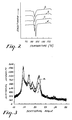
- Fig. 2 is a plot of differential scanning calorimetry scans for Examples 4-7 showing increasing exotherms with increasing layering.
- Fig. 3 is a plot of wide-angle x-ray scattering for Examples 5 and 7 showing increasing crystallinity with increasing layering.
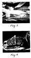
- Figs. 4 and 5 are scanning electron micrographs of web cross sections, for Examples 27 and 43, respectively, prepared by the invention method.
- Fig. 6 is a scanning electron micrograph top view of an Example 4 web.
- microfibers produced are prepared, in part, using the apparatus discussed, for example, in Wente, Van A., "Superfine Thermoplastic Fibers," Industrial Engineering Chemistry , Vol. 48, pp 1342-1346 and in Wente, Van A. et al., "Manufacture of Superfine Organic Fibers,” Report No. 4364 of the Naval Research Laboratories, published May 25, 1954, and U.S. Pat. Nos.
- the polymeric components are introduced into the die cavity 12 of die 10 from a separate splitter, splitter region or combining manifold 20, and into the, e.g., splitter from extruders, such as 22 and 23. Gear pumps and/or purgeblocks can also be used to finely control the polymer flowrate.
- the splitter or combining manifold 20 the separate polymeric component flowstreams are formed into a single layered flowstream. However, preferably, the separate flowstreams are kept out of direct contact for as long a period as possible prior to reaching the die 10.
- the separate polymeric flowstreams from the extruder(s) can be split in the splitter (20).
- the split or separate flowstreams are combined only immediately prior to reaching the die, or die orifices.
- the separate flowstreams are also preferably established into laminar flowstreams along closely parallel flowpaths.
- the flowstreams are then preferably combined so that at the point of combination, the individual flows are laminar, and the flowpaths are substantially parallel to each other and the flowpath of the resultant combined layered flowstream. This again minimizes turbulence and lateral flow instabilities of the separate flowstreams in and after the combining process.
- a suitable splitter 20, for the above-described step of combining separate flowstreams is one such as is disclosed, for example, in U.S. Pat. No. 3,557,265, which describes a manifold that forms two or three polymeric components into a multi-layered rectilinear melt flow.
- the polymer flowstreams from separate extruders are fed into plenums then to one of the three available series of ports or orifices, each series of ports is in fluid communication with one of the plenums.
- Each stream is thus split into a plurality of separated flowstreams by one of the series of ports, each with a height-to-width ratio of from about 0.01 to 1.
- the separated flowstreams, from each of the three plenum chambers, are then simultaneously coextruded by the three series of parts into a single channel in an interlacing manner to provide a multi-layered flowstream.
- the combined, multi-layered flowstream in the channel is then transformed (e.g., in a coat hanger transition piece), so that each layer extruded from the manifold orifices has a substantially smaller height-to-width ratio to provide a layered combined flowstream at the die orifices with an overall height of about 50 mils or less, preferably 15-30 mils or less.
- the width of the flowstream can be varied depending on the width of the die.
- Other suitable devices for providing a multi-layer flowstream are such as disclosed in U.S. Patents Nos.
- Cloeren disclose manifolds for bringing together diverse polymeric flowstreams into a single, multi-layer flowstream that is ordinarily sent through a coat hanger transition piece or neck-down zone prior to the film die outlet.
- the Cloeren arrangement has separate flow channels in the die cavity. Each flow channel is provided with a back-pressure cavity and a flow-restriction cavity, in successive order, each preferably defined by an adjustable vane.
- the adjustable vane arrangement permits minute adjustments of the relative layer thicknesses in the combined multi-layered flowstream.
- the multi-layer polymer flowstream from this arrangement need not necessarily be transformed to the appropriate length/width ratio, as this can be done by the vanes, and the combined flowstream can be fed directly into the die cavity 12.
- the multi-layer polymer flowstream is normally fed into the die cavity 12 as an integral flow. However, it is possible to keep the layer flowstreams separate in the die cavity 12 by use of separator plates that would allow the separate polymer flowstreams to combine immediately prior to reaching the die orifices.
- the multi-layer polymer flowstream is extruded through an array of side-by-side orifices 11.
- the feed can be formed into the appropriate profile in the cavity 12, suitably by use of a conventional coat hanger transition piece.
- Air slots 18, or the like are disposed on either side of the row of orifices 11 for directing uniform heated air at high velocity at the extruded layered melt streams.
- the air temperature is generally about that of the meltstream, although preferably 20-30°C higher than the polymer melt temperature. This hot, high-velocity air draws out and attenuates the extruded polymeric material, which will generally solidify after traveling a relatively short distance from the die 10.
- the solidified or partially solidified fibers are then formed into a web by known methods and collected (not shown).
- the collecting surface can be a solid or perforated surface in the form of a flat surface or a drum, a moving belt, or the like. If a perforated surface is used, the backside of the collecting surface can be exposed to a vacuum or low-pressure region to assist in the deposition of fibers, such as is disclosed in U.S. Pat. No. 4,103,058 (Humlicek). This low-pressure region allows one to form webs with pillowed low-density regions.
- the collector distance can generally be from 7.6 to 12.7 cm (3 to 50 inches) from the die face.
- the fibers are collected when they have more velocity and are more likely to have residual tackiness from incomplete cooling. This is particularly true for inherently more tacky thermoplastic materials, such as thermoplastic elastomeric materials. Moving the collector closer to the die face, e.g., preferably 7.6 to 12.7 cm) (3 to 12 inches), will result in stronger inter-fiber bonding and a less lofty web. Moving the collector back will generally tend to yield a loftier and less coherent web.
- the temperature of the polymers in the splitter region is generally about the temperature of the higher melting point component as it exits its extruder.
- This splitter region or manifold is typically integral with the die and is kept at the same temperature.
- the temperature of the separate polymer flowstreams can also be controlled to bring the polymers closer to a more suitable relative viscosity.
- the separate polymer flowstreams converge they should generally have an apparent viscosity of from 150 to 800 poise (measured by a capillary rheometer).
- the relative viscosities of the separate polymeric flowstreams to be converged should generally be fairly well matched. Empirically, this can be determined by varying the temperature of the melt and observing the crossweb properties of the collected web.
- the overall viscosity of the layered combined polymeric flowstream(s) at the die face should be from 150 to 800 poise, preferably from 200 to 400 poise.
- the differences in relative viscosities are preferably generally the same as when the separate polymeric flowstreams are first combined.
- the apparent viscosities of the polymeric flowstream(s) can be adjusted at this point by varying the temperatures as per U.S. Pat. No. 3,849,241 (Butin, et al).
- the size of the polymeric fibers formed depends to a large extent on the velocity and temperature of the attenuating airstream, the orifice diameter, the temperature of the melt stream, and the overall flow rate per orifice.
- the fibers formed have an average fiber diameter of less than about 10 micrometers.
- the polymers have larger average diameters, however, with an increasing tendency for the fibers to entwine into formations called "ropes". This is dependent on the polymer flow rates, of course, with polymer flow rates in the range of 0.05 to 0.5 gm/min/orifice generally being suitable.
- Coarser fibers e.g., up to 25 micrometers or more, can be used in certain circumstances such as large pore, or coarse, filter webs.
- the multi-layer microfibers of the invention can be admixed with other fibers or particulates prior to being collected.
- sorbent particulate matter or fibers can be incorporated into the coherent web of blown multi-layered fibers as discussed in U.S. Pat. Nos. 3,971,373 or 4,429,001.
- two separate streams of melt-blown fibers are established with the streams intersecting prior to collection of the fibers.
- the particulates, or fibers are entrained into an airstream, and this particulate-laden airstream is then directed at the intersection point of the two microfiber streams.
- melt-blown microfiber webs such as is disclosed, for example, in U.S. Pat. Nos. 4,118,531, 4,429,001 or 4,755,178, where particles or fibers are delivered into a single stream of melt-blown fibers.
- surfactants or binders can be incorporated into the web before, during or after its collection, such as by use of a spray jet. If applied before collection, the material is sprayed on the stream of microfibers, with or without added fibers or particles, traveling to the collection surface.
- microfibers are formed from a low modulus material forming one layer or layers and a relatively nonelastic material forming the other layer or layers.
- Low modulus material refers to any material that is capable of substantial elongation, e.g. preferably greater than about 100 percent, without breakage. At low stress levels, the Young's modulus is generally in the range from about 104 to 107 N/M2. These materials are preferably elastomers which will substantially resume their shape after being stretched. Such elastomers will preferably exhibit permanent set of about 20 percent or less, preferably 10 percent or less, when stretched at moderate elongations, preferably of about 100 percent. Elastomers include materials or blends, which are capable of undergoing elongations, preferably of up to 700-800% and more at room temperatures.
- the relatively nonelastic material is generally a more rigid or higher modulus material capable of being coextruded with the elastomeric or low modulus material. Further, the relatively nonelastic material must undergo permanent deformation or cold stretch at the stretch percentage that the elastomeric or low modulus material will undergo without significant elastic recovery.
- the Young's modulus of this material should generally be greater than 106 N/M2 and preferably greater than 107 N/M2.
- Webs formed from these multilayer fibers exhibit remarkable conformability, which is believed due to the extensibility of individual fibers in a coherent web structure under low levels of stress. Webs also exhibit a remarkable extensibility without the usual web breakage. This is believed to be attributable to a unique complimentary combination of properties from the individual layers in the multilayer fibers and from the interfiber relationships in the web as a whole.
- the preferably elastomeric low modulus layers allows one to lower the individual fiber composite modulus to a level that permits ready extensibility at relatively low stress levels. As such, when the web is tensioned, the applied stress will dissipate by elongation of individual fibers rather than concentrating at web weak points, which could result in fiber breakage and web failure.
- Fiber breakage of the individual fibers that undergo elongation is believed to be minimized by the relatively nonelastic material.
- the relatively nonelastic material is one that will undergo permanent deformation when stretched. Such materials also exhibit significant orientation when stretched, and their modulus value and strength tends to significantly increase at some point as they are stretched. Therefore, the relatively nonelastic material layers act as reinforcing elements at a critical elongation point. As adjacent unextended, or less extended, portions of the web are still relatively extensible, fully extended and oriented fibers are unlikely to be exposed to stress levels high enough to cause fiber and web breakage. It is believed that the layers of low modulus material act to distribute the stress while the layers of higher modulus material reinforce critically stressed portions of web thus decreasing the tendency for fiber and web failure. The stress on the web therefore has a tendency to be more widely distributed across the entire web rather than resulting in failure at web weak points.
- the low modulus material when the low modulus material is an elastomer it will have a tendency to resume its original shape after being elongated. This thus results in a tendency for the web to contract after being stretched.
- This web contraction has been found to vary significantly depending on the materials used in the elastomer layer and the higher modulus layer, the relative volume percent of the respective layers and the overall number of layers in the microfibers.
- the individual fibers that exhibit recovery also are self-crimping. Namely, the fibers tend to coil and recover into a springlike form.
- the web after recovery will generally exhibit elastic properties to the point of previous elongation. This can range from levels as low as a few percent to a greater than 100 or 200 percent.
- Fiber coiling and occasional separation of individual outer layers from stressed fibers also results in a relatively high degree of lofting in the resultant web.
- This lofting yields an improved softness or feel to the web, making it desirable for use in applications where it may make skin contact such as bandage backings, garment elastics, surgical drapes, medical tape backings or medical wraps.
- garments particular contemplated uses include uses in a disposable diaper or incontinent device as any elastic element, or a conformable body hugging portion such as an outer or inner cover sheet or a portion designed to engage the hips of the wearer, for a product designed to be stepped into or slipped on.
- the elastic recovery of stretched webs can be enhanced by heating the web.
- This heat-activated recovery can be used to advantage to create a heat-shrink elastic nonwoven web product for use in a wide Variety of applications, particularly when this is coupled with the conformable nature of the web.
- the nonwoven web When used as a tape backing, the nonwoven web can be coated with any conventional hot melt, solvent coated, or like adhesive suitable for application to nonwoven webs.
- adhesives can be applied by conventional techniques, such as solvent coating by methods such as reverse roll, knife-over-roll, gravure, wire wound rod, floating knife or air knife, hot-melt coating such as; by slot orifice coaters, roll coaters or extrusion coaters, at appropriate coating weights.
- solvent coating by methods such as reverse roll, knife-over-roll, gravure, wire wound rod, floating knife or air knife, hot-melt coating such as; by slot orifice coaters, roll coaters or extrusion coaters, at appropriate coating weights.
- the extensible nature of the web can have considerable effects on a previously applied adhesive layer. When the web is stretched, the adhesive layer, if continuous, will break up resulting in a breathable tape. Further, the amount of adhesive surface available for contact to a substrate will likely be significantly reduced.
- the tape could thus be used for single application purposes and be rendered nonfunctional when removed (as the web tape backing could be designed to yield when removed) if the adhesion is reduced to an appropriate level. This would make the tape well suited for certain tamper indicating uses as well as with products designed for single use only. Adhesives can also be applied after the web has been extended or stretched. Preferred for most applications would be pressure sensitive adhesives.
- the low modulus material can be any such material suitable for processing by melt blowing techniques. This would include polymers such as polyurethanes (e.g. "MorthaneTM", available from Morton Thiokol Corp.); A-B block copolymers where A is formed of poly(vinyl arene) moieties such as polystyrene, and B is an elastomeric mid-block such as a conjugated diene or a lower alkene in the form of a linear di- or tri-block copolymer, a star, radial or branched copolymer, such as elastomers sold as "KRATONTM” (Shell Chemical Co.); polyetheresters (such as "ArnitelTM” available from Akzo Plastics Co.); or polyamides (such as "PebaxTM” available from Autochem Co.).
- polyurethanes e.g. "MorthaneTM", available from Morton Thiokol Corp.
- Copolymers and blends can also be used.
- A-B block copolymer blends as described in U.S. Pat. No. 4,657,802 are suitable where such block copolymers are preferably blended with polyalkylenes.
- Other possible materials include ethylene copolymers such as ethylene vinyl acetates, ethylene/propylene copolymer elastomers or ethylene/propylene/diene terpolymer elastomers. Blends of all the above materials are also contemplated provided that the resulting material has a Young's modulus of approximately 107 N/M2 or less, preferably 106 N/M2 or less.
- the polymer blend can be stiffening aids such as polyvinylstyrenes, polystyrenes such as poly(alpha-methyl)styrene, polyesters, epoxies, polyolefins, e.g., polyethylene or certain ethylene/vinyl acetates, preferably those of higher molecular Weight, or coumarone-indene resin.
- stiffening aids such as polyvinylstyrenes, polystyrenes such as poly(alpha-methyl)styrene, polyesters, epoxies, polyolefins, e.g., polyethylene or certain ethylene/vinyl acetates, preferably those of higher molecular Weight, or coumarone-indene resin.
- Viscosity reducing materials and plasticizers can also be blended with the elastomers and low modulus extensible materials such as low molecular weight polyethylene and polypropylene polymers and copolymers, or tackifying resins such as WingtackTM aliphatic hydrocarbon tackifiers available from Goodyear Chemical Company. Tackifiers can also be used to increase the adhesiveness of an elastomeric low modulus layer to a relatively nonelastic layer. Examples of tackifiers include aliphatic or aromatic liquid tackifiers, polyterpene resin tackifiers, and hydrogenated tackifying resins. Aliphatic hydrocarbon resins are preferred.
- the relatively nonelastomeric layer material is a material capable of elongation and permanent deformation as discussed above, which is fiber forming.
- Useful materials include polyesters, such as polyethylene terephthalate; polyalkylenes, such as polyethylene or polypropylene; polyamides, such as nylons; polystyrenes; or polyarylsulfones.
- Also useful are certain slightly elastomeric materials such as some olefinic elastomeric materials such as some ethylene/propylene, or ethylene/propylene/diene elastomeric copolymers or other ethylenic copolymers such as some ethylene vinyl acetates.
- the relatively non-elastomeric layer material can also be a material capable of heat or sonic bonding to itself or other materials.
- a preferred material is disclosed in U.S. Patent No. 4,710,190, the substance of which is incorporated by reference, which describes a blend of high and low molecular weight portion polymers.
- the blends of high and low molecular weight portions are blends that exhibit tackiness and bonding characteristics at temperatures in the range of 50°C to 110°C.
- the high and low molecular weight portions can include ethylene- or propylene-based copolymers. Particularly preferred are copolymers with polar comonomers such as ethylene/vinyl acetate (EVA), or like materials (see, e.g., E.P.A.
- EVA and tackifiers such as synthetic hydrocarbon resins. These materials exhibit good bonding to polyethylene-based polymers or copolymer films such as polyethylene or EVA films.
- other heat- or sonic-bondable materials can be used as the relatively non-elastomeric layer, however, it is preferred that this material have a melting point at least about 15°C below that of the elastomeric layer so that the web retains some open structure following heat bonding. Suitable materials would include polyethylene polymers and blends such as disclosed in U.S. Patent No. 4,477,516.
- Heat or sonicly bondable materials often exhibit relatively high self-bonding characteristics under melt-blowing conditions and, as such, form very coherent webs without the elastomeric (or low modulus) material. Webs formed from these combinations of materials can be concentricly layered (e.g., sheath-core-type layering) with the heat sealable or sonicly sealable material as the external sheath layer and exhibit some of the properties of the longitudinally layered embodiments.
- an elastomeric layer (as a core layer or the like) and an outer bonding layer provides elastomeric and/or conformable webs capable of heat or sonic bonding to structures such as polyethylene polymer or copolymer films or webs.
- a property of the invention web when stretched and allowed to recover is the directionality of the resulting web's elasticity.
- the web will exhibit elastic properties substantially only in the direction the web is stretched.
- the elasticity is also limited by the point to which the web was originally stretched.
- the elastic behavior and loft of the web can thus be controlled to an appropriate level, depending on the application. For example, for bandage backings, a limited level of elasticity is all that is required. This desired level of elasticity could be obtained by adjusting the number of layers in the microfibers, the relative percent of the at least two layers (one of which is an elastomeric layer) or the degree or direction of elongation or stretch.
- a low degree (e.g., less than 50%) of elasticity is thus obtainable for uses such as medical wraps, bandages and the like. Higher degrees of elasticity (e.g, greater than 50%) are obtainable for uses such as the elastication of garments.
- the web when stretched also displays a noted lofting effect, which is dependant to some degree on the amount of recovery.
- This loft is highly desirable for garment and medical type uses.
- the increased loft will increase the web softness, breathability and wicking ability.
- a further feature of the invention webs is an ability for the webs to undergo further recovery when heated generally to a temperature greater than about 60°C. This is useful for typical heat shrink applications for elastic films.
- Fiber and web strength can be controlled within wide ranges for given combinations of polymers by varying, independently, the relative ratios of the polymers, the layer order in the microfibers, the number of layers, the collector distance and other process variables.
- the invention thus allows precise control of web strength by varying one or all of these variables.
- either one can advantageously comprise 1 to 99 volume percent of the total fiber volume, however, preferably the low modulus material will comprise at least about 10 percent of the fiber volume.
- the outside layers will still contribute significantly to the surface properties of the fibers forming the web without significantly modifying the bulk fiber properties, such as tensile strength and modulus behavior.
- the polymers with desirable bulk properties such as tensile strength (e.g., the relative nonelastic materials)
- materials having desirable surface properties such as good bondability (e.g., an elastomeric low modulus material)
- the outer layers will still contribute disproportionately to fiber surface properties, but will contribute more to the fiber bulk properties.
- the web properties can also be altered by variations in the number of layers employed at a given relative volume percent and layer arrangement.
- variation in the number of layers at least at a low number of layers, has a tendency to significantly vary the relative proportion of each polymer (assuming two polymeric materials) at the microfiber surface. This (assuming alternating layers of two polymeric materials) translates into variation of those web properties to which the microfiber surface properties significantly contribute.
- web properties can change depending on what polymer or composition comprises the outside layer(s).
- this variation in web properties based on surface area effects diminishes.
- the relative thicknesses of the individual fiber layers will tend to decrease, significantly decreasing the surface area effect of any individual layer.
- the individual fiber layer thicknesses can get well below 1 micrometer.
- the number of layers obtainable with the invention process is theoretically unlimited. Practically, the manufacture of a manifold, or the like, capable of splitting and/or combining multiple polymer streams into a very highly layered arrangement would be prohibitively complicated and expensive. Additionally, in order to obtain a flowstream of suitable dimensions for feeding to the die orifices, forming and then maintaining layering through a suitable transition piece can become difficult. A practical limit of 1,000 layers is contemplated, at which point the processing problems would likely outweigh any potential added property benefits.
- the webs formed can be of any suitable thickness for the desired end use. However, generally a thickness from 0.01 to 5 centimeters is suitable for most applications. Further, for some applications, the web can be a layer in a composite multi-layer structure.
- the other layers can be supporting webs, films (such as elastic films, semi-permeable films or impermeable films). Other layers could be used for purposes such as absorbency, surface texture, rigidification and can be non-woven webs formed of, for example, staple and/or melt-blown fibers.
- the other layers can be attached to the invention melt-blown web by conventional techniques such as heat bonding, binders or adhesives or mechanical engagement, such as hydroentanglement or needle punching.
- Other structures could also be included in a composite structure, such as reinforcing or elastic threads or strands, which would preferably be sandwiched between two layers of the composite structures. These strands or threads can likewise be attached by the conventional methods described above.
- a particular contemplated use for the nonwoven web is as a tape backing capable of being firmly bonded to a substrate, and removed therefrom by stretching the backing at an angle less than about 35°.
- These tapes are useful as mounting and joining tapes (e.g., adhesive on both faces) or for removable labels or the like (adhesive on one face).
- the highly extensible backing (having a Young's modulus of less than 50,000 PSI and preferably between 5,000 and 30,000 PSI) deforms along a propagation front creating a concentration of stress at the propagation front. This stress concentration results in adhesive failure at the deformation propagation front at relatively low forces. The tape can thus be removed cleanly at low forces, without damage to the substrate, yet provide a strong bond in use.
- the adhesive for this application should generally be extensible, yet can otherwise be of conventional formulations such as tackified natural or synthetic rubber pressure sensitive adhesives or acrylic based adhesives.
- the tape When applied, the tape should be unstretched or stretched to a low extent (e.g., to enhance conformability) so that the backing is still highly extensible (e.g., greater than 50%, and preferably greater than 150%).
- Webs, or composite structures including webs of the invention can be further processed after collection or assembly such as by calendaring or point embossing to increase web strength, provide a patterned surface, or fuse fibers at contact points in a web structure or the like; by orientation to provide increased web strength; by needle punching; heat or molding operations; coating, such as with adhesives to provide a tape structure, or the like.
- Tensile modulus data on the multi-layer BMF webs was obtained using an Instron Tensile Tester (Model 1122) with a 10.48 cm (2 in.) jaw gap and a crosshead speed of 25.4 cm/min. (10 in./min.). Web samples were 2.54 cm (1 in.) in width. Elastic recovery behavior of the webs was determined by stretching the sample to a predetermined elongation and measuring the length of the sample after release of the elongation force and allowing the sample to relax for a period of 1 minute.
- X-Ray diffraction data were collected using a Philips APD-3600 diffractometer (fitted with a Paur HTK temperature controller and hot stage). Copper K ⁇ radiation was employed with power tube settings of 45 kV and 4 mA and with intensity measurements made by means of a Scintillation detector. Scans within the 2-50 degree (2 ⁇ ) scattering region were performed for each sample at 25 degrees C and a 0.02 degree step increment and 2 second counting time.
- Conformability was measured according to the manufacturer's directions on a Handle-o-MeterTM Model 211, available from Thwing-Albert Instrument Co. using an 8 in. x 8 in. (20.3 cm x 20.3 cm) sample using a 1/4 in. (0.64 cm) slot width.
- a polypropylene/polyurethane multi-layer BMF web of the present invention was prepared using a melt-blowing process similar to that described, for example, in Wente, Van A., "Superfine Thermoplastic Fibers," in Industrial Engineering Chemistry , Vol. 48, pages 1342 et seq (1956), or in Report No. 4364 of the Naval Research Laboratories, published May 25, 1954, entitled “Manufacture of Superfine Organic Fibers” by Wente, Van A.; Boone, C.D.; and Fluharty, E.L., except that the BMF apparatus utilized two extruders, each of which was equipped with a gear pump to control the polymer melt flow, each pump feeding a five-layer feedblock splitter assembly similar to that described in U.S.
- the second extruder which was maintained at about 220°C, delivered a melt stream of a poly(esterurethane) (PU) resin ("MorthaneTM" PS 455-200, available from Morton Thiokol Corp.) to the feedblock.
- PU poly(esterurethane)
- the feedblock split the two melt streams.
- the polymer melt streams were merged in an alternating fashion into a five-layer melt stream on exiting the feedblock, with the outer layers being the PP resin.
- the gear pumps were adjusted so that a 75:25 pump ratio percent PP:PU polymer melt was delivered to the feedblock assembly and a 0.14 kg/hr/cm die width (0.8 lb/hr/in.) polymer throughput rate was maintained at the BMF die (260°C).
- the primary air temperature was maintained at approximately 220°C and at a pressure suitable to produce a uniform web with a 0.076 cm gap width. Webs were collected at a collector to BMF die distance of 30.5 cm (12 in.).
- the resulting BMF web comprising five-layer microfibers having an average diameter of less than about 10 micrometers, had a basis weight of 50 g/m2.
- a BMF web having a basis weight of 50 g/m2 and comprising five-layer microfibers having an average diameter of less than about 10 micrometers was prepared according to the procedure of Example 1, except that the PP and PU melt streams were delivered to the five-layer feedblock in a 50:50 ratio.
- a BMF web having a basis weight of 50 g/m2 and comprising five-layer microfibers having an average diameter of less than about 10 micrometers was prepared according to the procedure of Example 1, except that the PP and PU melt streams were delivered to the five-layer feedblock in a 25:75 ratio.
- a control web of the 800 MFR polypropylene resin was prepared according to the procedure of Example 1, except that only one extruder, which was maintained at 260°C, was used, and it was connected directly to the BMF die through a gear pump. The die and air temperatures were maintained at 260°C.
- the resulting BMF web had a basis weight of 50 g/m2 and an average fiber diameter of less than about 10 micrometers.
- a control web of the polyurethane resin (“MorthaneTM” PS455-200) was prepared according to the procedure of Example 1, except that only one extruder, which was maintained at 220°C, was used which was connected directly to the BMF die through a gear pump. The die and air temperatures were maintained at 220°C.
- the resulting BMF web had a basis weight of 50 g/m2 and an average fiber diameter of less than about 10 micrometers.
- Table 1 summarizes the tensile modulus values for BMF webs comprising five-layer microfibers of varying PP/PU polymer ratios.
- a BMF web having a basis weight of 100 g/m2 and comprising two-layer microfibers having an average diameter of less than about 10 micrometers was prepared according to the procedure of Example 3, except that the PP and PU melt streams were delivered to a two-layer feedblock, and the die and air temperatures were maintained at about 230°C. This sample was stretched 200% and released. This sample was then prepared for scanning electron micrograph analysis. Fig. 6 shows a top view of this stretched sample (200x). The machine direction conformability was 174 grams, and the cross direction conformability was 227 grams.
- a BMF web having a basis weight of 100 g/m2 and comprising three-layer microfibers having an average diameter of less than about 10 micrometers was prepared according to the procedure of Example 3, except that the PP and PU melt streams were delivered to a three-layer feedblock.
- the machine direction conformability was 188 grams, and the cross direction conformability was 277 grams.
- a BMF web having a basis weight of 100 g/m2 and comprising five-layer microfibers having an average diameter of less than about 10 micrometers was prepared according to the procedure of Example 3.
- Example 3 is a five-layer construction.
- the machine direction conformability was 185 grams, and the cross direction conformability was 252 grams.
- a BMF web having a basis weight of 100 g/m2 and comprising twenty-seven-layer microfibers having an average diameter of less than about 10 micrometers was prepared according to the procedure of Example 3, except that the PP and PU melt streams were delivered to a twenty-seven-layer feedblock.
- the machine direction conformability was 149 grams, and the cross direction conformability was 185 grams.
- Table 2 summarizes the modulus values for a series of BMF webs having a 25:75 PP:PU pump ratio, but varying numbers of layers in the microfibers.
- a BMF web having a basis weight of 100 g/m2 and comprising two-layer microfibers having an average diameter of less than about 10 micrometers was prepared according to the procedure of Example 1, except that a 105 MI low-density polyethylene (LLDPE, AspunTM 6806 available from Dow Chemical) was substituted for the polypropylene and a poly(esterurethane) (PU) resin ("Morthane TM" PS 440-200, available from Morton Thiokol Corp.) was substituted for the MorthaneTM PS 455-200, the extruder temperatures were maintained at 220°C and 230°C, respectively, the melt streams were delivered to a two-layer feedblock maintained at 230°C at a 75:25 ratio, the BMF die and primary air supply temperatures were maintained at 225°C and 215°C, respectively, and the collector distance was 30.5 cm.
- the machine direction conformability was 157 grams, and the cross direction conformability was 181 grams.
- a BMF web having a basis weight of 100 g/m2 and comprising two-layer microfibers having an average diameter of less than about 10 micrometers was prepared according to the procedure of Example 8, except that the PE and PU melt streams were delivered to the two-layer feedblock in a 50:50 ratio.
- the machine direction conformability was 115 grams, and the cross direction conformability was 150 grams.
- a BMF web having a basis weight of 100 g/m2 and comprising two-layer microfibers having an average diameter of less than about 10 micrometers was prepared according to the procedure of Example 8, except that the PE and PU melt streams were delivered to the two-layer feedblock in a 25:75 ratio.
- the machine direction conformability was 70 grams, and the cross direction conformability was 103 grams.
- a control web of the LLDPE resin (AspunTM 6806) was prepared according to the procedure of Example 1, except that only one extruder, which was maintained at 210°C, was used, and it was connected directly to the BMF die through a gear pump, and the die and air temperatures were maintained at 210°C, and the collector distance was 25.4 cm.
- the resulting BMF web had a basis weight of 100 g/m2 and an average fiber diameter of less than about 10 micrometers.
- a control web of the polyurethane resin (MorthaneTM PS440-200) was prepared according to the procedure of Example 1, except that only one extruder, which was maintained at 230°C, was used which was connected directly to the BMF die through a gear pump, and the die and air temperatures were maintained at 230°C.
- the resulting BMF web had a basis weight of 100 g/m2 and an average fiber diameter of less than about 10 micrometers.
- Table 3 summarizes the tensile modulus values for BMF webs comprising two-layer microfibers of varying PE/PU compositions.
- PET poly(ethylene terephthalate) resin
- line 20 was substituted for the polypropylene and a poly(esterurethane) (PU) resin (MorthaneTM PS 440-200, available from Morton Thiokol Corp.) was substituted for the MorthaneTM PS 455-200 (in a 75:25 ratio), the melt streams were delivered to the five-layer feedblock at about 280°C and about 230°C, respectively, and the feedblock, die and air temperatures were maintained at 280°C, 280°C and 270°C, respectively.
- PU poly(esterurethane)
- a BMF web having a basis weight of 50 g/m2 and comprising five-layer microfibers having an average diameter of less than about 10 micrometers was prepared according to the procedure of Example 11, except that the PET and PU melt streams were delivered to the five-layer feedblock in a 50:50 ratio.
- a BMF web having a basis weight of 50 g/m2 and comprising five-layer microfibers having an average diameter of less than about 10 micrometers was prepared according to the procedure of Example 11, except that the PET and PU melt streams were delivered to the five-layer feedblock in a 25:75 ratio.
- the resulting BMF web had a basis weight of 100 g/m2 and an average fiber diameter of less than about 10 micrometers.
- Table 4 summarizes the tensile modulus values for BMF webs comprising five-layer microfibers of varying PET/PU ratios.
- a BMF web having a basis weight of 50 g/m2 and comprising five-layer microfibers having an average diameter of less than about 10 micrometers was prepared according to the procedure of Example 1, except that a 60/40 blend of KratonTM G-1657, a hydrogenated styrene/ethylene-butylene/styrene A-B-A block copolymer (SEBS) available from Shell Chemical Corp., and a linear low-density polyethylene (LLDPE) AspunTM 6806, 105 MI, available from Dow Chemical, was substituted for the MorthaneTM PS 455-200, the extruder temperatures were maintained at 250°C and 270°C, respectively, the melt streams were delivered to a five-layer feedblock maintained at 270°C at a 75:25 ratio, and the die and primary air temperatures were maintained at 270°C and 255°C, respectively.
- SEBS hydrogenated styrene/ethylene-butylene/styrene A-B-A block copolymer
- a BMF web having a basis weight of 50 g/m2 and comprising five-layer microfibers having an average diameter of less than about 10 micrometers was prepared according to the procedure of Example 14, except that the PP and SEBS/LLDPE blend melt streams were delivered to the five-layer feedblock in a 50:50 ratio.
- a BMF web having a basis weight of 50 g/m2 and comprising five-layer microfibers having an average diameter of less than about 10 micrometers was prepared according to the procedure of Example 14, except that the PP and SEBS/LLDPE blend melt streams were delivered to the five-layer feedblock in a 25:75 ratio.
- a control web of the 60/40 SEBS/LLDPE blend was prepared according to the procedure of Example 1, except that only one extruder, which was maintained at 270°C, was used which was connected directly to the BMF die through a gear pump, and the die and air temperatures were maintained at 270°C.
- the resulting BMF web had a basis weight of 50 g/m2 and an average fiber diameter of less than about 10 micrometers.
- Table 5 summarizes the tensile modulus values for BMF webs comprising five-layer microfibers of varying PP//SEBS/LLDPE ratios.
- a BMF web having a basis weight of 50 g/m2 and comprising two-layer microfibers having an average diameter of less than about 10 micrometers was prepared according to the procedure of Example 14, except that a two-layer feedblock assembly was substituted for the five-layer feedblock.
- a BMF web having a basis weight of 50 g/m2 and comprising two-layer microfibers having an average diameter of less than about 10 micrometers was prepared according to the procedure of Example 17, except that the PP and SEBS/LLDPE blend melt streams were delivered to the two-layer feedblock in a 50:50 ratio.
- a BMF web having a basis weight of 50 g/m2 and comprising two-layer microfibers having an average diameter of less than about 10 micrometers was prepared according to the procedure of Example 17, except that the PP and SEBS/LLDPE blend melt streams were delivered to the two-layer feedblock in a 25:75 ratio.
- Table 6 summarizes the tensile modulus values for BMF webs comprising two-layer microfibers of varying PP//SEBS/LLDPE compositions.
- a BMF web having a basis weight of 100 g/m2 and comprising two-layer microfibers having an average diameter of less than about 10 micrometers was prepared according to the procedure of Example 8, except that the collector distance was 15.2 cm (6 in.).
- a BMF web having a basis weight of 100 g/m2 and comprising two-layer microfibers having an average diameter of less than about 10 micrometers was prepared according to the procedure of Example 9, except that the collector distance was 15.2 cm (6 in.).
- the machine direction conformability was 101 grams, and the cross direction conformability was 162 grams.
- a BMF web having a basis weight of 100 g/m2 and comprising two-layer microfibers having an average diameter of less than about 10 micrometers was prepared according to the procedure of Example 10, except that the collector distance was 15.2 cm (6 in.).
- the machine direction conformability was 56 grams, and the cross direction conformability was 85 grams.
- Table 7 summarizes the MD modulus values for a number of two-layer PE/PU web compositions which were prepared utilizing two collector distances.
- a BMF web having a basis weight of 100 g/m2 and comprising twenty-seven-layer microfibers having an average diameter of less than about 10 micrometers was prepared according to the procedure of Example 7, except that the PP and PU melt streams were delivered to the twenty-seven-layer feedblock such that the outer layer of the fibers was PU rather than PP (I/O vs O/I for Example 7) and the die orifices had a diameter of about 0.0017 inches versus 0.0015 inches for Example 7.
- Table 8 summarizes the MD modulus for two twenty-seven-layer layer PP/PU microfiber webs where the order of polymer feed into the feedblock was reversed, thereby inverting the composition of the outer layer of the microfiber.
- a BMF web having a basis weight of 100 g/m2 and comprising twenty-seven-layer microfibers having an average diameter of less than about 10 micrometers was prepared according to the procedure of Example 7, except that the PP and PU melt streams were delivered to the twenty-seven-layer feedblock which was maintained at 250°C in a 75/25 ratio from two extruders which were maintained at 250°C and 210°C, respectively, and a smooth collector drum was positioned 15.2 cm from the BMF die.
- the PP and PU melt streams were introduced into the feedblock assembly such that the outer layer of the fiber was PP (O/I).
- a BMF web having a basis weight of 100 g/m2 and comprising twenty-seven-layer microfibers having an average diameter of less than about 10 micrometers was prepared according to the procedure of Example 24, except that the PP and PU melt streams were delivered to the twenty-seven-layer feedblock in a 50/50 ratio.
- the machine direction conformability was 296 grams, and the cross direction conformability was 507 grams.
- a BMF web having a basis weight of 100 g/m2 and comprising twenty-seven-layer microfibers having an average diameter of less than about 10 micrometers was prepared according to the procedure of Example 24 except that the PP and PU melt streams were delivered to the twenty-seven-layer feedblock in a 25/75 ratio.
- a BMF web having a basis weight of 100 g/m2 and comprising twenty-seven-layer microfibers having an average diameter of less than about 10 micrometers was prepared according to the procedure of Example 24, except that a LLDPE (AspunTM 6806, 105 MFR, available from Dow Chemical) was substituted for the PP and the PE and PU melt streams were delivered to the twenty-seven-layer feedblock which was maintained at 210°C in a 75/25 ratio from two extruders which were both maintained at 210°C.
- a scanning electron micrograph (Fig. 4-2000x) of a cross section of this sample was prepared after the polyurethane was washed out with tetrahydrofuran. The sample was then cut, mounted and prepared for analysis by standard techniques.
- a BMF web having a basis weight of 100 g/m2 and comprising twenty-seven-layer microfibers having an average diameter of less than about 10 micrometers was prepared according to the procedure of Example 27, except that the PE and PU melt streams were delivered to the twenty-seven-layer feedblock in a 50/50 ratio.
- a BMF web having a basis weight of 100 g/m2 and comprising twenty-seven-layer microfibers having an average diameter of less than about 10 micrometers was prepared according to the procedure of Example 27, except that the PE and PU melt streams were delivered to the twenty-seven-layer feedblock in a 25/75 ratio.
- Table 9 summarizes the MD tensile modulus for several twenty-seven-layer microfiber webs where the composition of the outer layer of the fiber varied between PP and PE.
- BMF webs comprising multi-layered BMF fibers
- the recovery behavior of BMF webs comprising multi-layered BMF fibers was studied by subjecting samples of BMF webs consisting of various multi-layered fiber compositions to elongations of 100, 200 and 400% and monitoring the length of the samples after the elongation force had been removed and the samples allowed to relax for a period of one minute.
- Elastic recovery was calculated using the formula: Results of this study are summarized in Tables 10 - 15.
- a BMF web having a basis weight of 100 g/m2 and comprising three-layer microfibers having an average diameter of less than about 10 micrometers was prepared according to the procedure of Example 22, except that the PE and PU polymer melt streams were delivered to a three-layer feedblock in a manner such that the outer layer of the fiber was PU (I/O configuration).
- a BMF web having a basis weight of 100 g/m2 and comprising three-layer microfibers having an average diameter of less than about 10 micrometers was prepared according to the procedure of Example 21, except that the PE and PU polymer melt streams were delivered to a three-layer feedblock in a manner such that the outer layer of the fiber was PU (I/O configuration).
- a BMF web having a basis weight of 50 g/m2 and comprising three-layer microfibers having an average diameter of less than about 10 micrometers was prepared according to the procedure of Example 3, except that the PP and PU melt streams were delivered to a three-layer feedblock.
- a BMF web having a basis weight of 50 g/m2 and comprising three-layer microfibers having an average diameter of less than about 10 micrometers was prepared according to the procedure of Example 2 except, that the PP and PU melt streams were delivered to a three-layer feedblock.
- a BMF web having a basis weight of 75 g/m2 and comprising three-layer microfibers having an average diameter of less than about 10 micrometers was prepared according to the procedure of Example 3.
- a BMF web having a basis weight of 155 g/m2 and comprising three-layer microfibers having an average diameter of less than about 10 micrometers was prepared according to the procedure of Example 3.
- a BMF web having a basis weight of 100 g/m2 and comprising three-layer microfibers having an average diameter of less than about 10 micrometers was prepared according to the procedure of Example 3, except that PellathaneTM 2103-80WC, a poly(etherurethane) available from Dow Chemical Corp. was substituted for the MorthaneTM PS 455-200, the extruders delivering the PP and PU melts were maintained at 240°C and 210°C, respectively, the PP and PU melt streams were delivered to a three-layer feedblock, which was maintained at 240°C, and the die and air temperatures were maintained at 230°C and 215°C, respectively.
- a BMF web having a basis weight of 190 g/m2 and comprising three-layer microfibers having an average diameter of less than about 10 micrometers was prepared according to the procedure of Example 36.
- a BMF web having a basis weight of 100 g/m2 and comprising five-layer microfibers having an average diameter of less than about 10 micrometers was prepared according to the procedure of Example 3, except that PellathaneTM 2103-80WC, a poly(etherurethane) available from Dow Chemical Corp. was substituted for the MorthaneTM PS 455-200, the extruders delivering the PP and PU melts were maintained at 240°C and 210°C, respectively, the PP and PU melt streams were delivered to a five-layer feedblock, which was maintained at 240°C, and the die and air temperatures were maintained at 230°C and 220°C, respectively.
- a control web of the poly(etherurethane) resin (PellathaneTM 2103-80WC) was prepared according to the procedure of Example 1, except that only one extruder, which was maintained at 210°C, was used which was connected directly to the BMF die through a gear pump and the die and air temperatures were maintained at 210°C.
- the resulting BMF web had a basis weight of 100 g/m2 and an average fiber diameter of less than about 10 micrometers.
- a BMF web having a basis weight of 100 g/m2 and comprising five-layer microfibers having an average diameter of less than about 10 micrometers was prepared according to the procedure of Example 1, except that KratonTM G-1657, (SEBS) was substituted for the MorthaneTM PS 455-200, both extruder temperatures were maintained at 260°C, the melt streams were delivered to a five-layer feedblock maintained at 240°C at a 62.5:37.5 ratio, and the die and primary air temperatures maintained at 240°C and 275°C, respectively.
- a BMF web having a basis weight of 100 g/m2 and comprising five-layer microfibers having an average diameter of less than about 10 micrometers was prepared according to the procedure of Example 39, except that PP and SEBS melt streams were delivered to the feedblock in a 25:75 ratio.
- a BMF web having a basis weight of 100 g/m2 and comprising two layer microfibers having an average diameter of less than about 10 micrometers was prepared according to the procedure of Example 1 except that a poly(esterurethane) (PU) resin (Morthane PS 440-200, available from Morton Thiokol Corp.) was substituted for the Morthane PS 455-200, the second extruder was maintained at 230°C, and the PP and PU melt streams were delivered to the two layer feed block in a 50:50 ratio.
- PU poly(esterurethane)
- a BMF web having a basis weight of 100 g/m2 and comprising two layer microfibers having an average diameter of less than about 10 micrometers was prepared according to the procedure of Example 1 except that a poly(esterurethane) (PU) resin (Morthane PS 440-200, available from Morton Thiokol Corp.) was substituted for the Morthane PS 455-200, the second extruder was maintained at 230°C, and the PP and PU melt streams were delivered to the two layer feed block in a 25:75 ratio.
- PU poly(esterurethane)
- a BMF web was prepared according to the procedure of Example 8 except that the PE and PU melt stream were delivered to a three-layer feedblock.
- the samples were prepared for SEM analysis as per Example 27 except the PU was not removed, Fig. 5(1000x).
Abstract
Description
- The invention relates to a conformable or stretchable novel melt-blown non-woven web useful in a variety of applications and the method for its production. The nonwoven webs include melt-blown microfibers comprised of longitudinally distinct polymeric layers of at least one elastomeric or low modulus material and a second higher modulus or non-elastomeric material.
- It has been proposed in U.S. Patent No. 3,841,953 to form nonwoven webs of melt-blown fibers using polymer blends, in order to obtain webs having novel properties. A problem with these webs however is that the polymer interfaces causes weaknesses in the individual fibers that causes severe fiber breakage and weak points. The web tensile properties reported in this patent are generally inferior to those of webs made of corresponding single polymer fibers. This web weakness is likely due to weak points in the web from incompatible polymer blends and the extremely short fibers in the web.
- A method for producing bicomponent fibers in a melt-blown process is disclosed in U.S. Pat. No. 4,729,371. The polymeric materials are fed from two conduits which meet at a 180 degree angle. The polymer flowstreams then converge and exit via a third conduit at a 90 degree angle to the two feed conduits. The two feedstreams form a layered flowstream in this third conduit, which bilayered flowstream is fed to a row of side-by-side orifices in a melt-blowing die. The bilayered polymer melt streams extruded from the orifices are then formed into microfibers by a high air velocity attenuation or a "melt-blown" process. The product formed is used specifically to form a web useful for molding into a filter material. The process disclosed concerns forming two-layer microfibers. The process also has no ability to produce webs where web properties are adjusted by fine control over the fiber layering arrangements and/or the number of layers. There is also not disclosed a stretchable and preferably high strength web.
- U.S. Pat. No. 4,557,972 discloses a sheath-core composite fiber of an allegedly ultrafine denier (less than 0.5 denier). The fibers are formed from a special spinneret for forming large, three-component fibers, with two of the components forming ultrafine included material in a matrix of the third component. Ultrafine fibers are then obtained by selectively removing the matrix (the "sea") material, leaving the included material as fine fibers. This process is complex and cannot practically be used to form non-woven webs. Similar processes are proposed by U.S. Pat. Nos. 4,460,649, 4,627,950 and 4,381,274, which discuss various "islands-in-a-sea" processes for forming multi-component yarns. U.S. Pat. No. 4,117,194 describes a bicomponent textile spun fiber with improved crimp properties.
- U.S. Pat. Nos. 3,672,802 and 3,681,189 describe spun fibers allegedly having a large number of layers each of a separate polymer component. The two polymers are fed into a specially designed manifold that repeatedly combines, splits and re-combines a polymer stream(s) to form a somewhat stratified stream of the two distinct polymers. The process disclosed in these two patents is similar to mixing the polymers due to the significant amount of non-linear polymer flow introduced during the repeated splitting and re-combining of the polymer stream(s). However, the splitting and re-combining is done in line with the polymer flow, and the resulting fibers apparently have distinct longitudinal regions of one or the other polymer rather than the substantially non-directional arrangement of separate polymer regions one would obtain with incomplete batch mixing. However, the polymer layers in the fibers are very indistinct and irregular. Further, due to the excessively long contact period between the polymers, it would be difficult to handle polymers with significantly different melt viscosities by this process. The fibers produced are textile size, and the layering effect is done to improve certain properties over homogeneous fibers (not webs) such as dyeability properties, electrification properties, hydrophilic properties or tensile properties. No mention is made of how to improve web conformability and/or stretchability.
- The present invention is directed to a process for producing a non-woven web of longitudinally layered melt-blown microfibers and the nonwoven, melt-blown web, comprising layers of a low modulus or elastomeric materials and adjacent layers of higher modulus or nonelastic materials. The microfibers are produced by a process comprising first feeding separate polymer melt streams to a manifold means, optionally separating at least one of the polymer melt streams into at least two distinct streams, and combining all the melt streams, including the separated streams, into a single polymer melt stream of longitudinally distinct layers, preferably of the at least two different polymeric materials arrayed in an alternating manner. The combined melt stream is then extruded through fine orifices and formed into a highly conformable and stretchable web of melt-blown microfibers.
- Fig. 1 is a schematic view of an apparatus useful in the practice of the invention method.
- Fig. 2 is a plot of differential scanning calorimetry scans for Examples 4-7 showing increasing exotherms with increasing layering.
- Fig. 3 is a plot of wide-angle x-ray scattering for Examples 5 and 7 showing increasing crystallinity with increasing layering.
- Figs. 4 and 5 are scanning electron micrographs of web cross sections, for Examples 27 and 43, respectively, prepared by the invention method.
- Fig. 6 is a scanning electron micrograph top view of an Example 4 web.
- The microfibers produced are prepared, in part, using the apparatus discussed, for example, in Wente, Van A., "Superfine Thermoplastic Fibers," Industrial Engineering Chemistry, Vol. 48, pp 1342-1346 and in Wente, Van A. et al., "Manufacture of Superfine Organic Fibers," Report No. 4364 of the Naval Research Laboratories, published May 25, 1954, and U.S. Pat. Nos. 3,849,241 (Butin et al.), 3,825,379 (Lohkamp et al.), 4,818,463 (Buehning), 4,986,743 (Buehning), 4,295,809 (Mikami et al.) or 4,375,718 (Wadsworth et al.). These apparatuses and methods are useful in the invention process in the portion shown as die 10 in Fig. 1, which could be of any of these conventional designs.
- The polymeric components are introduced into the
die cavity 12 of die 10 from a separate splitter, splitter region or combiningmanifold 20, and into the, e.g., splitter from extruders, such as 22 and 23. Gear pumps and/or purgeblocks can also be used to finely control the polymer flowrate. In the splitter or combiningmanifold 20, the separate polymeric component flowstreams are formed into a single layered flowstream. However, preferably, the separate flowstreams are kept out of direct contact for as long a period as possible prior to reaching the die 10. The separate polymeric flowstreams from the extruder(s) can be split in the splitter (20). The split or separate flowstreams are combined only immediately prior to reaching the die, or die orifices. This minimizes the possibility of flow instabilities generating in the separate flowstreams after being combined in the single layered flowstream, which tends to result in non-uniform and discontinuous longitudinal layers in the multi-layered microfibers. Flow instabilities can also have adverse effects on non-woven web properties such as strength, temperature stability, or other desirable properties obtainable with the invention process. - The separate flowstreams are also preferably established into laminar flowstreams along closely parallel flowpaths. The flowstreams are then preferably combined so that at the point of combination, the individual flows are laminar, and the flowpaths are substantially parallel to each other and the flowpath of the resultant combined layered flowstream. This again minimizes turbulence and lateral flow instabilities of the separate flowstreams in and after the combining process. It has been found that a
suitable splitter 20, for the above-described step of combining separate flowstreams, is one such as is disclosed, for example, in U.S. Pat. No. 3,557,265, which describes a manifold that forms two or three polymeric components into a multi-layered rectilinear melt flow. The polymer flowstreams from separate extruders are fed into plenums then to one of the three available series of ports or orifices, each series of ports is in fluid communication with one of the plenums. Each stream is thus split into a plurality of separated flowstreams by one of the series of ports, each with a height-to-width ratio of from about 0.01 to 1. The separated flowstreams, from each of the three plenum chambers, are then simultaneously coextruded by the three series of parts into a single channel in an interlacing manner to provide a multi-layered flowstream. The combined, multi-layered flowstream in the channel is then transformed (e.g., in a coat hanger transition piece), so that each layer extruded from the manifold orifices has a substantially smaller height-to-width ratio to provide a layered combined flowstream at the die orifices with an overall height of about 50 mils or less, preferably 15-30 mils or less. The width of the flowstream can be varied depending on the width of the die. Other suitable devices for providing a multi-layer flowstream are such as disclosed in U.S. Patents Nos. 3,924,990 (Schrenk); 3,687,589 (Schrenk); 3,759,647 (Schrenk et al.) or 4,197,069 (Cloeren), all of which, except Cloeren, disclose manifolds for bringing together diverse polymeric flowstreams into a single, multi-layer flowstream that is ordinarily sent through a coat hanger transition piece or neck-down zone prior to the film die outlet. The Cloeren arrangement has separate flow channels in the die cavity. Each flow channel is provided with a back-pressure cavity and a flow-restriction cavity, in successive order, each preferably defined by an adjustable vane. The adjustable vane arrangement permits minute adjustments of the relative layer thicknesses in the combined multi-layered flowstream. The multi-layer polymer flowstream from this arrangement need not necessarily be transformed to the appropriate length/width ratio, as this can be done by the vanes, and the combined flowstream can be fed directly into thedie cavity 12. - The multi-layer polymer flowstream is normally fed into the
die cavity 12 as an integral flow. However, it is possible to keep the layer flowstreams separate in thedie cavity 12 by use of separator plates that would allow the separate polymer flowstreams to combine immediately prior to reaching the die orifices. - From the
die cavity 12, the multi-layer polymer flowstream is extruded through an array of side-by-side orifices 11. As discussed above, prior to this extrusion, the feed can be formed into the appropriate profile in thecavity 12, suitably by use of a conventional coat hanger transition piece.Air slots 18, or the like, are disposed on either side of the row of orifices 11 for directing uniform heated air at high velocity at the extruded layered melt streams. The air temperature is generally about that of the meltstream, although preferably 20-30°C higher than the polymer melt temperature. This hot, high-velocity air draws out and attenuates the extruded polymeric material, which will generally solidify after traveling a relatively short distance from thedie 10. The solidified or partially solidified fibers are then formed into a web by known methods and collected (not shown). The collecting surface can be a solid or perforated surface in the form of a flat surface or a drum, a moving belt, or the like. If a perforated surface is used, the backside of the collecting surface can be exposed to a vacuum or low-pressure region to assist in the deposition of fibers, such as is disclosed in U.S. Pat. No. 4,103,058 (Humlicek). This low-pressure region allows one to form webs with pillowed low-density regions. The collector distance can generally be from 7.6 to 12.7 cm (3 to 50 inches) from the die face. With closer placement of the collector, the fibers are collected when they have more velocity and are more likely to have residual tackiness from incomplete cooling. This is particularly true for inherently more tacky thermoplastic materials, such as thermoplastic elastomeric materials. Moving the collector closer to the die face, e.g., preferably 7.6 to 12.7 cm) (3 to 12 inches), will result in stronger inter-fiber bonding and a less lofty web. Moving the collector back will generally tend to yield a loftier and less coherent web. - The temperature of the polymers in the splitter region is generally about the temperature of the higher melting point component as it exits its extruder. This splitter region or manifold is typically integral with the die and is kept at the same temperature. The temperature of the separate polymer flowstreams can also be controlled to bring the polymers closer to a more suitable relative viscosity. When the separate polymer flowstreams converge, they should generally have an apparent viscosity of from 150 to 800 poise (measured by a capillary rheometer). The relative viscosities of the separate polymeric flowstreams to be converged should generally be fairly well matched. Empirically, this can be determined by varying the temperature of the melt and observing the crossweb properties of the collected web. The more uniform the crossweb properties, the better the viscosity match. The overall viscosity of the layered combined polymeric flowstream(s) at the die face should be from 150 to 800 poise, preferably from 200 to 400 poise. The differences in relative viscosities are preferably generally the same as when the separate polymeric flowstreams are first combined. The apparent viscosities of the polymeric flowstream(s) can be adjusted at this point by varying the temperatures as per U.S. Pat. No. 3,849,241 (Butin, et al).
- The size of the polymeric fibers formed depends to a large extent on the velocity and temperature of the attenuating airstream, the orifice diameter, the temperature of the melt stream, and the overall flow rate per orifice. At high air volume rates, the fibers formed have an average fiber diameter of less than about 10 micrometers. However, there is an increased difficulty in obtaining webs having uniform properties as the air flow rate increases. At more moderate air flow rates, the polymers have larger average diameters, however, with an increasing tendency for the fibers to entwine into formations called "ropes". This is dependent on the polymer flow rates, of course, with polymer flow rates in the range of 0.05 to 0.5 gm/min/orifice generally being suitable. Coarser fibers, e.g., up to 25 micrometers or more, can be used in certain circumstances such as large pore, or coarse, filter webs.
- The multi-layer microfibers of the invention can be admixed with other fibers or particulates prior to being collected. For example, sorbent particulate matter or fibers can be incorporated into the coherent web of blown multi-layered fibers as discussed in U.S. Pat. Nos. 3,971,373 or 4,429,001. In these patents, two separate streams of melt-blown fibers are established with the streams intersecting prior to collection of the fibers. The particulates, or fibers, are entrained into an airstream, and this particulate-laden airstream is then directed at the intersection point of the two microfiber streams. Other methods of incorporating particulates or fibers, such as staple fibers, bulking fibers or binding fibers, can be used with the invention melt-blown microfiber webs, such as is disclosed, for example, in U.S. Pat. Nos. 4,118,531, 4,429,001 or 4,755,178, where particles or fibers are delivered into a single stream of melt-blown fibers.
- Other materials such as surfactants or binders can be incorporated into the web before, during or after its collection, such as by use of a spray jet. If applied before collection, the material is sprayed on the stream of microfibers, with or without added fibers or particles, traveling to the collection surface.
- The microfibers are formed from a low modulus material forming one layer or layers and a relatively nonelastic material forming the other layer or layers.
- Low modulus material refers to any material that is capable of substantial elongation, e.g. preferably greater than about 100 percent, without breakage. At low stress levels, the Young's modulus is generally in the range from about 10⁴ to 10⁷ N/M². These materials are preferably elastomers which will substantially resume their shape after being stretched. Such elastomers will preferably exhibit permanent set of about 20 percent or less, preferably 10 percent or less, when stretched at moderate elongations, preferably of about 100 percent. Elastomers include materials or blends, which are capable of undergoing elongations, preferably of up to 700-800% and more at room temperatures.
- The relatively nonelastic material is generally a more rigid or higher modulus material capable of being coextruded with the elastomeric or low modulus material. Further, the relatively nonelastic material must undergo permanent deformation or cold stretch at the stretch percentage that the elastomeric or low modulus material will undergo without significant elastic recovery. The Young's modulus of this material should generally be greater than 10⁶ N/M² and preferably greater than 10⁷ N/M².
- Webs formed from these multilayer fibers exhibit remarkable conformability, which is believed due to the extensibility of individual fibers in a coherent web structure under low levels of stress. Webs also exhibit a remarkable extensibility without the usual web breakage. This is believed to be attributable to a unique complimentary combination of properties from the individual layers in the multilayer fibers and from the interfiber relationships in the web as a whole. The preferably elastomeric low modulus layers allows one to lower the individual fiber composite modulus to a level that permits ready extensibility at relatively low stress levels. As such, when the web is tensioned, the applied stress will dissipate by elongation of individual fibers rather than concentrating at web weak points, which could result in fiber breakage and web failure.
- Fiber breakage of the individual fibers that undergo elongation is believed to be minimized by the relatively nonelastic material. As discussed above, preferably the relatively nonelastic material is one that will undergo permanent deformation when stretched. Such materials also exhibit significant orientation when stretched, and their modulus value and strength tends to significantly increase at some point as they are stretched. Therefore, the relatively nonelastic material layers act as reinforcing elements at a critical elongation point. As adjacent unextended, or less extended, portions of the web are still relatively extensible, fully extended and oriented fibers are unlikely to be exposed to stress levels high enough to cause fiber and web breakage. It is believed that the layers of low modulus material act to distribute the stress while the layers of higher modulus material reinforce critically stressed portions of web thus decreasing the tendency for fiber and web failure. The stress on the web therefore has a tendency to be more widely distributed across the entire web rather than resulting in failure at web weak points.
- Further, when the low modulus material is an elastomer it will have a tendency to resume its original shape after being elongated. This thus results in a tendency for the web to contract after being stretched. This web contraction has been found to vary significantly depending on the materials used in the elastomer layer and the higher modulus layer, the relative volume percent of the respective layers and the overall number of layers in the microfibers. Generally the most recovery is exhibited by webs formed of microfibers having a relatively low number of layers and a higher volume percent of the elastomer layer material. The individual fibers that exhibit recovery also are self-crimping. Namely, the fibers tend to coil and recover into a springlike form. The web after recovery will generally exhibit elastic properties to the point of previous elongation. This can range from levels as low as a few percent to a greater than 100 or 200 percent.
- Fiber coiling and occasional separation of individual outer layers from stressed fibers also results in a relatively high degree of lofting in the resultant web. This lofting yields an improved softness or feel to the web, making it desirable for use in applications where it may make skin contact such as bandage backings, garment elastics, surgical drapes, medical tape backings or medical wraps. With respect to garments, particular contemplated uses include uses in a disposable diaper or incontinent device as any elastic element, or a conformable body hugging portion such as an outer or inner cover sheet or a portion designed to engage the hips of the wearer, for a product designed to be stepped into or slipped on.
- In certain embodiments, the elastic recovery of stretched webs can be enhanced by heating the web. This heat-activated recovery can be used to advantage to create a heat-shrink elastic nonwoven web product for use in a wide Variety of applications, particularly when this is coupled with the conformable nature of the web.
- When used as a tape backing, the nonwoven web can be coated with any conventional hot melt, solvent coated, or like adhesive suitable for application to nonwoven webs. These adhesives can be applied by conventional techniques, such as solvent coating by methods such as reverse roll, knife-over-roll, gravure, wire wound rod, floating knife or air knife, hot-melt coating such as; by slot orifice coaters, roll coaters or extrusion coaters, at appropriate coating weights. The extensible nature of the web can have considerable effects on a previously applied adhesive layer. When the web is stretched, the adhesive layer, if continuous, will break up resulting in a breathable tape. Further, the amount of adhesive surface available for contact to a substrate will likely be significantly reduced. The tape could thus be used for single application purposes and be rendered nonfunctional when removed (as the web tape backing could be designed to yield when removed) if the adhesion is reduced to an appropriate level. This would make the tape well suited for certain tamper indicating uses as well as with products designed for single use only. Adhesives can also be applied after the web has been extended or stretched. Preferred for most applications would be pressure sensitive adhesives.
- The low modulus material can be any such material suitable for processing by melt blowing techniques. This would include polymers such as polyurethanes (e.g. "Morthane™", available from Morton Thiokol Corp.); A-B block copolymers where A is formed of poly(vinyl arene) moieties such as polystyrene, and B is an elastomeric mid-block such as a conjugated diene or a lower alkene in the form of a linear di- or tri-block copolymer, a star, radial or branched copolymer, such as elastomers sold as "KRATON™" (Shell Chemical Co.); polyetheresters (such as "Arnitel™" available from Akzo Plastics Co.); or polyamides (such as "Pebax™" available from Autochem Co.). Copolymers and blends can also be used. For example, A-B block copolymer blends as described in U.S. Pat. No. 4,657,802 are suitable where such block copolymers are preferably blended with polyalkylenes. Other possible materials include ethylene copolymers such as ethylene vinyl acetates, ethylene/propylene copolymer elastomers or ethylene/propylene/diene terpolymer elastomers. Blends of all the above materials are also contemplated provided that the resulting material has a Young's modulus of approximately 10⁷ N/M² or less, preferably 10⁶ N/M² or less.
- For extremely low modulus elastomers, it may be desirable to provide greater rigidity and strength. For example, up to 50 weight percent, but preferably less than 30 weight percent, of the polymer blend can be stiffening aids such as polyvinylstyrenes, polystyrenes such as poly(alpha-methyl)styrene, polyesters, epoxies, polyolefins, e.g., polyethylene or certain ethylene/vinyl acetates, preferably those of higher molecular Weight, or coumarone-indene resin.
- Viscosity reducing materials and plasticizers can also be blended with the elastomers and low modulus extensible materials such as low molecular weight polyethylene and polypropylene polymers and copolymers, or tackifying resins such as Wingtack™ aliphatic hydrocarbon tackifiers available from Goodyear Chemical Company. Tackifiers can also be used to increase the adhesiveness of an elastomeric low modulus layer to a relatively nonelastic layer. Examples of tackifiers include aliphatic or aromatic liquid tackifiers, polyterpene resin tackifiers, and hydrogenated tackifying resins. Aliphatic hydrocarbon resins are preferred.
- The relatively nonelastomeric layer material is a material capable of elongation and permanent deformation as discussed above, which is fiber forming. Useful materials include polyesters, such as polyethylene terephthalate; polyalkylenes, such as polyethylene or polypropylene; polyamides, such as nylons; polystyrenes; or polyarylsulfones. Also useful are certain slightly elastomeric materials such as some olefinic elastomeric materials such as some ethylene/propylene, or ethylene/propylene/diene elastomeric copolymers or other ethylenic copolymers such as some ethylene vinyl acetates.
- The relatively non-elastomeric layer material can also be a material capable of heat or sonic bonding to itself or other materials. A preferred material is disclosed in U.S. Patent No. 4,710,190, the substance of which is incorporated by reference, which describes a blend of high and low molecular weight portion polymers. The blends of high and low molecular weight portions are blends that exhibit tackiness and bonding characteristics at temperatures in the range of 50°C to 110°C. The high and low molecular weight portions can include ethylene- or propylene-based copolymers. Particularly preferred are copolymers with polar comonomers such as ethylene/vinyl acetate (EVA), or like materials (see, e.g., E.P.A. 366379 A2). Also usable are blends of EVA and tackifiers such as synthetic hydrocarbon resins. These materials exhibit good bonding to polyethylene-based polymers or copolymer films such as polyethylene or EVA films. Although not as preferred, other heat- or sonic-bondable materials can be used as the relatively non-elastomeric layer, however, it is preferred that this material have a melting point at least about 15°C below that of the elastomeric layer so that the web retains some open structure following heat bonding. Suitable materials would include polyethylene polymers and blends such as disclosed in U.S. Patent No. 4,477,516.
- Heat or sonicly bondable materials often exhibit relatively high self-bonding characteristics under melt-blowing conditions and, as such, form very coherent webs without the elastomeric (or low modulus) material. Webs formed from these combinations of materials can be concentricly layered (e.g., sheath-core-type layering) with the heat sealable or sonicly sealable material as the external sheath layer and exhibit some of the properties of the longitudinally layered embodiments.
- The combination of an elastomeric layer (as a core layer or the like) and an outer bonding layer provides elastomeric and/or conformable webs capable of heat or sonic bonding to structures such as polyethylene polymer or copolymer films or webs. This finds particular use where properties of conformability, elasticity and breathability are important, and where the web could be heat or sonicly bonded to other components of a device, such as medical devices or incontinent devices (e.g., a diaper film or the like).
- A property of the invention web when stretched and allowed to recover is the directionality of the resulting web's elasticity. The web will exhibit elastic properties substantially only in the direction the web is stretched. The elasticity is also limited by the point to which the web was originally stretched. The elastic behavior and loft of the web can thus be controlled to an appropriate level, depending on the application. For example, for bandage backings, a limited level of elasticity is all that is required. This desired level of elasticity could be obtained by adjusting the number of layers in the microfibers, the relative percent of the at least two layers (one of which is an elastomeric layer) or the degree or direction of elongation or stretch. A low degree (e.g., less than 50%) of elasticity is thus obtainable for uses such as medical wraps, bandages and the like. Higher degrees of elasticity (e.g, greater than 50%) are obtainable for uses such as the elastication of garments.
- As previously discussed, the web when stretched also displays a noted lofting effect, which is dependant to some degree on the amount of recovery. This loft is highly desirable for garment and medical type uses. The increased loft will increase the web softness, breathability and wicking ability.
- A further feature of the invention webs is an ability for the webs to undergo further recovery when heated generally to a temperature greater than about 60°C. This is useful for typical heat shrink applications for elastic films.
- Fiber and web strength can be controlled within wide ranges for given combinations of polymers by varying, independently, the relative ratios of the polymers, the layer order in the microfibers, the number of layers, the collector distance and other process variables. The invention thus allows precise control of web strength by varying one or all of these variables.
- Theoretically, for webs formed from the above described two types of layers either one can advantageously comprise 1 to 99 volume percent of the total fiber volume, however, preferably the low modulus material will comprise at least about 10 percent of the fiber volume. At the low end of this volume range, the outside layers will still contribute significantly to the surface properties of the fibers forming the web without significantly modifying the bulk fiber properties, such as tensile strength and modulus behavior. In this manner, the polymers with desirable bulk properties, such as tensile strength (e.g., the relative nonelastic materials), can be combined with materials having desirable surface properties, such as good bondability (e.g., an elastomeric low modulus material), to provide melt-blown webs with a high relative proportion of the desirable properties from each polymer. At higher percentages, the outer layers will still contribute disproportionately to fiber surface properties, but will contribute more to the fiber bulk properties.
- With the invention, the web properties can also be altered by variations in the number of layers employed at a given relative volume percent and layer arrangement. As described above, variation in the number of layers, at least at a low number of layers, has a tendency to significantly vary the relative proportion of each polymer (assuming two polymeric materials) at the microfiber surface. This (assuming alternating layers of two polymeric materials) translates into variation of those web properties to which the microfiber surface properties significantly contribute. Thus, web properties can change depending on what polymer or composition comprises the outside layer(s). However, as the number of layers increases, this variation in web properties based on surface area effects diminishes. At higher-layer numbers, the relative thicknesses of the individual fiber layers will tend to decrease, significantly decreasing the surface area effect of any individual layer. For the preferred melt-blown microfibers with average diameters of less than 10 micrometers, the individual fiber layer thicknesses can get well below 1 micrometer.
- Additional effects on the fiber and web properties can be attributed to increases in the number of fiber layers alone. Specifically, it has been found that web modulus increases with increases in the number of individual layers while the elastic recovery behavior of the stretched web goes down significantly. Although not wishing to be bound by theory, it is believed that the decrease in individual layer thicknesses in the microfiber has a significant effect on the crystalline structure and behavior of the component polymers. For example, spherulitic growth could be constrained by adjacent layers resulting in more fine-grained structures. Further, the interfacial layer boundaries may constrain transverse polymer flow in the orifice increasing the relative percent of axial flow, tending to increase the degree of order of the polymers in the layered form and hence could increase crystallinity in this manner. These factors can likely influence the macro scale behavior of the component fibers in the web and hence web behavior itself.
- Further, with increased microfiber layering, the number of interfaces, and interfacial area, between adjacent layers increases significantly. This could tend to increase strength due to increased reinforcement and constrainment of the individual layers. It has also been found that it becomes increasingly difficult to separate the fiber inner layers as the total number of layers in the fibers increase. This is true even for relatively incompatible polymers that would ordinarily require compatibilizers or bonding layers to prevent layer separation.
- The number of layers obtainable with the invention process is theoretically unlimited. Practically, the manufacture of a manifold, or the like, capable of splitting and/or combining multiple polymer streams into a very highly layered arrangement would be prohibitively complicated and expensive. Additionally, in order to obtain a flowstream of suitable dimensions for feeding to the die orifices, forming and then maintaining layering through a suitable transition piece can become difficult. A practical limit of 1,000 layers is contemplated, at which point the processing problems would likely outweigh any potential added property benefits.
- The webs formed can be of any suitable thickness for the desired end use. However, generally a thickness from 0.01 to 5 centimeters is suitable for most applications. Further, for some applications, the web can be a layer in a composite multi-layer structure. The other layers can be supporting webs, films (such as elastic films, semi-permeable films or impermeable films). Other layers could be used for purposes such as absorbency, surface texture, rigidification and can be non-woven webs formed of, for example, staple and/or melt-blown fibers. The other layers can be attached to the invention melt-blown web by conventional techniques such as heat bonding, binders or adhesives or mechanical engagement, such as hydroentanglement or needle punching. Other structures could also be included in a composite structure, such as reinforcing or elastic threads or strands, which would preferably be sandwiched between two layers of the composite structures. These strands or threads can likewise be attached by the conventional methods described above.
- A particular contemplated use for the nonwoven web is as a tape backing capable of being firmly bonded to a substrate, and removed therefrom by stretching the backing at an angle less than about 35°. These tapes are useful as mounting and joining tapes (e.g., adhesive on both faces) or for removable labels or the like (adhesive on one face). The highly extensible backing (having a Young's modulus of less than 50,000 PSI and preferably between 5,000 and 30,000 PSI) deforms along a propagation front creating a concentration of stress at the propagation front. This stress concentration results in adhesive failure at the deformation propagation front at relatively low forces. The tape can thus be removed cleanly at low forces, without damage to the substrate, yet provide a strong bond in use. The adhesive for this application should generally be extensible, yet can otherwise be of conventional formulations such as tackified natural or synthetic rubber pressure sensitive adhesives or acrylic based adhesives. When applied, the tape should be unstretched or stretched to a low extent (e.g., to enhance conformability) so that the backing is still highly extensible (e.g., greater than 50%, and preferably greater than 150%).
- Webs, or composite structures including webs of the invention, can be further processed after collection or assembly such as by calendaring or point embossing to increase web strength, provide a patterned surface, or fuse fibers at contact points in a web structure or the like; by orientation to provide increased web strength; by needle punching; heat or molding operations; coating, such as with adhesives to provide a tape structure, or the like.
- The following examples are provided to illustrate presently contemplated preferred embodiments and the best mode for practicing the invention, but are not intended to be limiting thereof.
- Tensile modulus data on the multi-layer BMF webs was obtained using an Instron Tensile Tester (Model 1122) with a 10.48 cm (2 in.) jaw gap and a crosshead speed of 25.4 cm/min. (10 in./min.). Web samples were 2.54 cm (1 in.) in width. Elastic recovery behavior of the webs was determined by stretching the sample to a predetermined elongation and measuring the length of the sample after release of the elongation force and allowing the sample to relax for a period of 1 minute.
- X-Ray diffraction data were collected using a Philips APD-3600 diffractometer (fitted with a Paur HTK temperature controller and hot stage). Copper Kα radiation was employed with power tube settings of 45 kV and 4 mA and with intensity measurements made by means of a Scintillation detector. Scans within the 2-50 degree (2Θ) scattering region were performed for each sample at 25 degrees C and a 0.02 degree step increment and 2 second counting time.
- Conformability was measured according to the manufacturer's directions on a Handle-o-Meter™ Model 211, available from Thwing-Albert Instrument Co. using an 8 in. x 8 in. (20.3 cm x 20.3 cm) sample using a 1/4 in. (0.64 cm) slot width.
- Melting and crystallization behavior of the polymeric components in the multi-layered BMF webs were studied using a Perkin-Elmer Model DSC-7 Differential Scanning Calorimeter equipped with a System 4 analyzer. Heating scans were carried out at 10 or 20°C per minute with a holding time of three (3) minutes above the melting temperature followed by cooling at a rate of 10°C per minute. Areas under the melting endotherm and the crystallization exotherm provided an indication of the amount of crystallinity in the polymeric components of the multi-layered BMF webs.
- A polypropylene/polyurethane multi-layer BMF web of the present invention was prepared using a melt-blowing process similar to that described, for example, in Wente, Van A., "Superfine Thermoplastic Fibers," in Industrial Engineering Chemistry, Vol. 48, pages 1342 et seq (1956), or in Report No. 4364 of the Naval Research Laboratories, published May 25, 1954, entitled "Manufacture of Superfine Organic Fibers" by Wente, Van A.; Boone, C.D.; and Fluharty, E.L., except that the BMF apparatus utilized two extruders, each of which was equipped with a gear pump to control the polymer melt flow, each pump feeding a five-layer feedblock splitter assembly similar to that described in U.S. Pat. Nos. 3,480,502 (Chisholm et al.) and 3,487,505 (Schrenk) which was connected to a melt-blowing die having circular smooth surfaced orifices (10/cm) with a 5:1 length to diameter ratio. The first extruder (260°C) delivered a melt stream of a 800 melt flow rate (MFR) polypropylene (PP) resin (PP 3495G, available from Exxon Chemical Corp.), to the feedblock assembly which was heated to about 260°C. The second extruder, which was maintained at about 220°C, delivered a melt stream of a poly(esterurethane) (PU) resin ("Morthane™" PS 455-200, available from Morton Thiokol Corp.) to the feedblock. The feedblock split the two melt streams. The polymer melt streams were merged in an alternating fashion into a five-layer melt stream on exiting the feedblock, with the outer layers being the PP resin.
- The gear pumps were adjusted so that a 75:25 pump ratio percent PP:PU polymer melt was delivered to the feedblock assembly and a 0.14 kg/hr/cm die width (0.8 lb/hr/in.) polymer throughput rate was maintained at the BMF die (260°C). The primary air temperature was maintained at approximately 220°C and at a pressure suitable to produce a uniform web with a 0.076 cm gap width. Webs were collected at a collector to BMF die distance of 30.5 cm (12 in.). The resulting BMF web, comprising five-layer microfibers having an average diameter of less than about 10 micrometers, had a basis weight of 50 g/m².
- A BMF web having a basis weight of 50 g/m² and comprising five-layer microfibers having an average diameter of less than about 10 micrometers was prepared according to the procedure of Example 1, except that the PP and PU melt streams were delivered to the five-layer feedblock in a 50:50 ratio.
- A BMF web having a basis weight of 50 g/m² and comprising five-layer microfibers having an average diameter of less than about 10 micrometers was prepared according to the procedure of Example 1, except that the PP and PU melt streams were delivered to the five-layer feedblock in a 25:75 ratio.
- A control web of the 800 MFR polypropylene resin was prepared according to the procedure of Example 1, except that only one extruder, which was maintained at 260°C, was used, and it was connected directly to the BMF die through a gear pump. The die and air temperatures were maintained at 260°C. The resulting BMF web had a basis weight of 50 g/m² and an average fiber diameter of less than about 10 micrometers.
- A control web of the polyurethane resin ("Morthane™" PS455-200) was prepared according to the procedure of Example 1, except that only one extruder, which was maintained at 220°C, was used which was connected directly to the BMF die through a gear pump. The die and air temperatures were maintained at 220°C. The resulting BMF web had a basis weight of 50 g/m² and an average fiber diameter of less than about 10 micrometers.
- Table 1 summarizes the tensile modulus values for BMF webs comprising five-layer microfibers of varying PP/PU polymer ratios.

- A BMF web having a basis weight of 100 g/m² and comprising two-layer microfibers having an average diameter of less than about 10 micrometers was prepared according to the procedure of Example 3, except that the PP and PU melt streams were delivered to a two-layer feedblock, and the die and air temperatures were maintained at about 230°C. This sample was stretched 200% and released. This sample was then prepared for scanning electron micrograph analysis. Fig. 6 shows a top view of this stretched sample (200x). The machine direction conformability was 174 grams, and the cross direction conformability was 227 grams.
- A BMF web having a basis weight of 100 g/m² and comprising three-layer microfibers having an average diameter of less than about 10 micrometers was prepared according to the procedure of Example 3, except that the PP and PU melt streams were delivered to a three-layer feedblock. The machine direction conformability was 188 grams, and the cross direction conformability was 277 grams.
- A BMF web having a basis weight of 100 g/m² and comprising five-layer microfibers having an average diameter of less than about 10 micrometers was prepared according to the procedure of Example 3. Example 3 is a five-layer construction. The machine direction conformability was 185 grams, and the cross direction conformability was 252 grams.
- A BMF web having a basis weight of 100 g/m² and comprising twenty-seven-layer microfibers having an average diameter of less than about 10 micrometers was prepared according to the procedure of Example 3, except that the PP and PU melt streams were delivered to a twenty-seven-layer feedblock. The machine direction conformability was 149 grams, and the cross direction conformability was 185 grams.
- Table 2 summarizes the modulus values for a series of BMF webs having a 25:75 PP:PU pump ratio, but varying numbers of layers in the microfibers.

- The effect that the number of layers within the microfiber cross-section had on the crystallization behavior of the PP/PU BMF webs was studied using differential scanning calorimetry the results of which are graphically presented in Figure 2. An examination of the crystallization exotherms for the BMF webs of Examples 4, 5, 6 and 7 (a, b, c and d, respectively), which corresponds to blown microfibers having 2, 3, 5 and 27 layers, respectively, indicates that the peak of the crystallization exotherm for the web of Example 7 is approximately 6°C higher than the corresponding peak values for webs comprising blown microfibers having fewer layers. This data suggests that the crystallization process is enhanced in the microfibers having 27 layers, which is further supported by the examination of the wide angle X-ray scattering data that is illustrated in Figure 3 and confirms higher crystallinity in the PP of the 27 layer microfiber web samples (e corresponds to Example 7 and f corresponds to Example 5 after washing out the PU with tetrahydrofuran solvent).
- A BMF web having a basis weight of 100 g/m² and comprising two-layer microfibers having an average diameter of less than about 10 micrometers was prepared according to the procedure of Example 1, except that a 105 MI low-density polyethylene (LLDPE, Aspun™ 6806 available from Dow Chemical) was substituted for the polypropylene and a poly(esterurethane) (PU) resin ("MorthaneTM" PS 440-200, available from Morton Thiokol Corp.) was substituted for the Morthane™ PS 455-200, the extruder temperatures were maintained at 220°C and 230°C, respectively, the melt streams were delivered to a two-layer feedblock maintained at 230°C at a 75:25 ratio, the BMF die and primary air supply temperatures were maintained at 225°C and 215°C, respectively, and the collector distance was 30.5 cm. The machine direction conformability was 157 grams, and the cross direction conformability was 181 grams.
- A BMF web having a basis weight of 100 g/m² and comprising two-layer microfibers having an average diameter of less than about 10 micrometers was prepared according to the procedure of Example 8, except that the PE and PU melt streams were delivered to the two-layer feedblock in a 50:50 ratio. The machine direction conformability was 115 grams, and the cross direction conformability was 150 grams.
- A BMF web having a basis weight of 100 g/m² and comprising two-layer microfibers having an average diameter of less than about 10 micrometers was prepared according to the procedure of Example 8, except that the PE and PU melt streams were delivered to the two-layer feedblock in a 25:75 ratio. The machine direction conformability was 70 grams, and the cross direction conformability was 103 grams.
- A control web of the LLDPE resin (Aspun™ 6806) was prepared according to the procedure of Example 1, except that only one extruder, which was maintained at 210°C, was used, and it was connected directly to the BMF die through a gear pump, and the die and air temperatures were maintained at 210°C, and the collector distance was 25.4 cm. The resulting BMF web had a basis weight of 100 g/m² and an average fiber diameter of less than about 10 micrometers.
- A control web of the polyurethane resin (Morthane™ PS440-200) was prepared according to the procedure of Example 1, except that only one extruder, which was maintained at 230°C, was used which was connected directly to the BMF die through a gear pump, and the die and air temperatures were maintained at 230°C. The resulting BMF web had a basis weight of 100 g/m² and an average fiber diameter of less than about 10 micrometers.
- Table 3 summarizes the tensile modulus values for BMF webs comprising two-layer microfibers of varying PE/PU compositions.

- A BMF web having a basis weight of 50 g/m² and comprising five-layer microfibers having an average diameter of less than about 10 micrometers was prepared according to the procedure of Example 1, except that a poly(ethylene terephthalate) resin (PET having an I.V. = 0.60 and a melting point of about 257°C, prepared as described in U.S. Patent No. 4,939,008, col. 2, line 6 to col. 3, line 20) was substituted for the polypropylene and a poly(esterurethane) (PU) resin (Morthane™ PS 440-200, available from Morton Thiokol Corp.) was substituted for the Morthane™ PS 455-200 (in a 75:25 ratio), the melt streams were delivered to the five-layer feedblock at about 280°C and about 230°C, respectively, and the feedblock, die and air temperatures were maintained at 280°C, 280°C and 270°C, respectively.
- A BMF web having a basis weight of 50 g/m² and comprising five-layer microfibers having an average diameter of less than about 10 micrometers was prepared according to the procedure of Example 11, except that the PET and PU melt streams were delivered to the five-layer feedblock in a 50:50 ratio.
- A BMF web having a basis weight of 50 g/m² and comprising five-layer microfibers having an average diameter of less than about 10 micrometers was prepared according to the procedure of Example 11, except that the PET and PU melt streams were delivered to the five-layer feedblock in a 25:75 ratio.
- A control web of the poly(ethylene terephthalate) (I.V. = 0.60) resin was prepared according to the procedure of Example 1, except that only one extruder, which was maintained at about 300°C, was used which was connected directly to the BMF die through a gear pump, and the die and air temperatures were maintained at 300°C and 305°C, respectively. The resulting BMF web had a basis weight of 100 g/m² and an average fiber diameter of less than about 10 micrometers.
- Table 4 summarizes the tensile modulus values for BMF webs comprising five-layer microfibers of varying PET/PU ratios.

- A BMF web having a basis weight of 50 g/m² and comprising five-layer microfibers having an average diameter of less than about 10 micrometers was prepared according to the procedure of Example 1, except that a 60/40 blend of Kraton™ G-1657, a hydrogenated styrene/ethylene-butylene/styrene A-B-A block copolymer (SEBS) available from Shell Chemical Corp., and a linear low-density polyethylene (LLDPE) Aspun™ 6806, 105 MI, available from Dow Chemical, was substituted for the Morthane™ PS 455-200, the extruder temperatures were maintained at 250°C and 270°C, respectively, the melt streams were delivered to a five-layer feedblock maintained at 270°C at a 75:25 ratio, and the die and primary air temperatures were maintained at 270°C and 255°C, respectively.
- A BMF web having a basis weight of 50 g/m² and comprising five-layer microfibers having an average diameter of less than about 10 micrometers was prepared according to the procedure of Example 14, except that the PP and SEBS/LLDPE blend melt streams were delivered to the five-layer feedblock in a 50:50 ratio.
- A BMF web having a basis weight of 50 g/m² and comprising five-layer microfibers having an average diameter of less than about 10 micrometers was prepared according to the procedure of Example 14, except that the PP and SEBS/LLDPE blend melt streams were delivered to the five-layer feedblock in a 25:75 ratio.
- A control web of the 60/40 SEBS/LLDPE blend was prepared according to the procedure of Example 1, except that only one extruder, which was maintained at 270°C, was used which was connected directly to the BMF die through a gear pump, and the die and air temperatures were maintained at 270°C. The resulting BMF web had a basis weight of 50 g/m² and an average fiber diameter of less than about 10 micrometers.
- Table 5 summarizes the tensile modulus values for BMF webs comprising five-layer microfibers of varying PP//SEBS/LLDPE ratios.

- A BMF web having a basis weight of 50 g/m² and comprising two-layer microfibers having an average diameter of less than about 10 micrometers was prepared according to the procedure of Example 14, except that a two-layer feedblock assembly was substituted for the five-layer feedblock.
- A BMF web having a basis weight of 50 g/m² and comprising two-layer microfibers having an average diameter of less than about 10 micrometers was prepared according to the procedure of Example 17, except that the PP and SEBS/LLDPE blend melt streams were delivered to the two-layer feedblock in a 50:50 ratio.
- A BMF web having a basis weight of 50 g/m² and comprising two-layer microfibers having an average diameter of less than about 10 micrometers was prepared according to the procedure of Example 17, except that the PP and SEBS/LLDPE blend melt streams were delivered to the two-layer feedblock in a 25:75 ratio.
- Table 6 summarizes the tensile modulus values for BMF webs comprising two-layer microfibers of varying PP//SEBS/LLDPE compositions.

- A BMF web having a basis weight of 100 g/m² and comprising two-layer microfibers having an average diameter of less than about 10 micrometers was prepared according to the procedure of Example 8, except that the collector distance was 15.2 cm (6 in.).
- A BMF web having a basis weight of 100 g/m² and comprising two-layer microfibers having an average diameter of less than about 10 micrometers was prepared according to the procedure of Example 9, except that the collector distance was 15.2 cm (6 in.). The machine direction conformability was 101 grams, and the cross direction conformability was 162 grams.
- A BMF web having a basis weight of 100 g/m² and comprising two-layer microfibers having an average diameter of less than about 10 micrometers was prepared according to the procedure of Example 10, except that the collector distance was 15.2 cm (6 in.). The machine direction conformability was 56 grams, and the cross direction conformability was 85 grams.
- Table 7 summarizes the MD modulus values for a number of two-layer PE/PU web compositions which were prepared utilizing two collector distances.

- A BMF web having a basis weight of 100 g/m² and comprising twenty-seven-layer microfibers having an average diameter of less than about 10 micrometers was prepared according to the procedure of Example 7, except that the PP and PU melt streams were delivered to the twenty-seven-layer feedblock such that the outer layer of the fibers was PU rather than PP (I/O vs O/I for Example 7) and the die orifices had a diameter of about 0.0017 inches versus 0.0015 inches for Example 7.
- Table 8 summarizes the MD modulus for two twenty-seven-layer layer PP/PU microfiber webs where the order of polymer feed into the feedblock was reversed, thereby inverting the composition of the outer layer of the microfiber.

- A BMF web having a basis weight of 100 g/m² and comprising twenty-seven-layer microfibers having an average diameter of less than about 10 micrometers was prepared according to the procedure of Example 7, except that the PP and PU melt streams were delivered to the twenty-seven-layer feedblock which was maintained at 250°C in a 75/25 ratio from two extruders which were maintained at 250°C and 210°C, respectively, and a smooth collector drum was positioned 15.2 cm from the BMF die. The PP and PU melt streams were introduced into the feedblock assembly such that the outer layer of the fiber was PP (O/I).
- A BMF web having a basis weight of 100 g/m² and comprising twenty-seven-layer microfibers having an average diameter of less than about 10 micrometers was prepared according to the procedure of Example 24, except that the PP and PU melt streams were delivered to the twenty-seven-layer feedblock in a 50/50 ratio. The machine direction conformability was 296 grams, and the cross direction conformability was 507 grams.
- A BMF web having a basis weight of 100 g/m² and comprising twenty-seven-layer microfibers having an average diameter of less than about 10 micrometers was prepared according to the procedure of Example 24 except that the PP and PU melt streams were delivered to the twenty-seven-layer feedblock in a 25/75 ratio.
- A BMF web having a basis weight of 100 g/m² and comprising twenty-seven-layer microfibers having an average diameter of less than about 10 micrometers was prepared according to the procedure of Example 24, except that a LLDPE (Aspun™ 6806, 105 MFR, available from Dow Chemical) was substituted for the PP and the PE and PU melt streams were delivered to the twenty-seven-layer feedblock which was maintained at 210°C in a 75/25 ratio from two extruders which were both maintained at 210°C. A scanning electron micrograph (Fig. 4-2000x) of a cross section of this sample was prepared after the polyurethane was washed out with tetrahydrofuran. The sample was then cut, mounted and prepared for analysis by standard techniques.
- A BMF web having a basis weight of 100 g/m² and comprising twenty-seven-layer microfibers having an average diameter of less than about 10 micrometers was prepared according to the procedure of Example 27, except that the PE and PU melt streams were delivered to the twenty-seven-layer feedblock in a 50/50 ratio.
- A BMF web having a basis weight of 100 g/m² and comprising twenty-seven-layer microfibers having an average diameter of less than about 10 micrometers was prepared according to the procedure of Example 27, except that the PE and PU melt streams were delivered to the twenty-seven-layer feedblock in a 25/75 ratio.
- Table 9 summarizes the MD tensile modulus for several twenty-seven-layer microfiber webs where the composition of the outer layer of the fiber varied between PP and PE.

- The recovery behavior of BMF webs comprising multi-layered BMF fibers was studied by subjecting samples of BMF webs consisting of various multi-layered fiber compositions to elongations of 100, 200 and 400% and monitoring the length of the samples after the elongation force had been removed and the samples allowed to relax for a period of one minute. Elastic recovery was calculated using the formula:

Results of this study are summarized in Tables 10 - 15. - A BMF web having a basis weight of 100 g/m² and comprising three-layer microfibers having an average diameter of less than about 10 micrometers was prepared according to the procedure of Example 22, except that the PE and PU polymer melt streams were delivered to a three-layer feedblock in a manner such that the outer layer of the fiber was PU (I/O configuration).
- A BMF web having a basis weight of 100 g/m² and comprising three-layer microfibers having an average diameter of less than about 10 micrometers was prepared according to the procedure of Example 21, except that the PE and PU polymer melt streams were delivered to a three-layer feedblock in a manner such that the outer layer of the fiber was PU (I/O configuration).
- A BMF web having a basis weight of 50 g/m² and comprising three-layer microfibers having an average diameter of less than about 10 micrometers was prepared according to the procedure of Example 3, except that the PP and PU melt streams were delivered to a three-layer feedblock.
- A BMF web having a basis weight of 50 g/m² and comprising three-layer microfibers having an average diameter of less than about 10 micrometers was prepared according to the procedure of Example 2 except, that the PP and PU melt streams were delivered to a three-layer feedblock.
- A BMF web having a basis weight of 75 g/m² and comprising three-layer microfibers having an average diameter of less than about 10 micrometers was prepared according to the procedure of Example 3.
- A BMF web having a basis weight of 155 g/m² and comprising three-layer microfibers having an average diameter of less than about 10 micrometers was prepared according to the procedure of Example 3.
- A BMF web having a basis weight of 100 g/m² and comprising three-layer microfibers having an average diameter of less than about 10 micrometers was prepared according to the procedure of Example 3, except that Pellathane™ 2103-80WC, a poly(etherurethane) available from Dow Chemical Corp. was substituted for the Morthane™ PS 455-200, the extruders delivering the PP and PU melts were maintained at 240°C and 210°C, respectively, the PP and PU melt streams were delivered to a three-layer feedblock, which was maintained at 240°C, and the die and air temperatures were maintained at 230°C and 215°C, respectively.
- A BMF web having a basis weight of 190 g/m² and comprising three-layer microfibers having an average diameter of less than about 10 micrometers was prepared according to the procedure of Example 36.
- A BMF web having a basis weight of 100 g/m² and comprising five-layer microfibers having an average diameter of less than about 10 micrometers was prepared according to the procedure of Example 3, except that Pellathane™ 2103-80WC, a poly(etherurethane) available from Dow Chemical Corp. was substituted for the Morthane™ PS 455-200, the extruders delivering the PP and PU melts were maintained at 240°C and 210°C, respectively, the PP and PU melt streams were delivered to a five-layer feedblock, which was maintained at 240°C, and the die and air temperatures were maintained at 230°C and 220°C, respectively.
- A control web of the poly(etherurethane) resin (Pellathane™ 2103-80WC) was prepared according to the procedure of Example 1, except that only one extruder, which was maintained at 210°C, was used which was connected directly to the BMF die through a gear pump and the die and air temperatures were maintained at 210°C. The resulting BMF web had a basis weight of 100 g/m² and an average fiber diameter of less than about 10 micrometers.
- A BMF web having a basis weight of 100 g/m² and comprising five-layer microfibers having an average diameter of less than about 10 micrometers was prepared according to the procedure of Example 1, except that Kraton™ G-1657, (SEBS) was substituted for the Morthane™ PS 455-200, both extruder temperatures were maintained at 260°C, the melt streams were delivered to a five-layer feedblock maintained at 240°C at a 62.5:37.5 ratio, and the die and primary air temperatures maintained at 240°C and 275°C, respectively.
- A BMF web having a basis weight of 100 g/m² and comprising five-layer microfibers having an average diameter of less than about 10 micrometers was prepared according to the procedure of Example 39, except that PP and SEBS melt streams were delivered to the feedblock in a 25:75 ratio.
- A BMF web having a basis weight of 100 g/m² and comprising two layer microfibers having an average diameter of less than about 10 micrometers was prepared according to the procedure of Example 1 except that a poly(esterurethane) (PU) resin (Morthane PS 440-200, available from Morton Thiokol Corp.) was substituted for the Morthane PS 455-200, the second extruder was maintained at 230°C, and the PP and PU melt streams were delivered to the two layer feed block in a 50:50 ratio.
- A BMF web having a basis weight of 100 g/m² and comprising two layer microfibers having an average diameter of less than about 10 micrometers was prepared according to the procedure of Example 1 except that a poly(esterurethane) (PU) resin (Morthane PS 440-200, available from Morton Thiokol Corp.) was substituted for the Morthane PS 455-200, the second extruder was maintained at 230°C, and the PP and PU melt streams were delivered to the two layer feed block in a 25:75 ratio.


- In addition to monitoring the web recovery under ambient conditions, samples of several webs were subjected to post elongation annealing at elevated temperatures to determine if further recovery would be realized at elevated temperatures. Unless indicated otherwise, the web samples were placed in a circulating air oven at the indicated temperature for a period of 0.5 minutes, and the samples measured to determine if further recovery had occurred. Results of these studies are summarized in Tables 16-18x.


- A BMF web was prepared according to the procedure of Example 8 except that the PE and PU melt stream were delivered to a three-layer feedblock. The samples were prepared for SEM analysis as per Example 27 except the PU was not removed, Fig. 5(1000x).
Claims (16)
- An extensible nonwoven web comprising melt-blown microfibers, each of said melt-blown microfibers having at least two substantially continuous layers throughout said microfiber length comprised of at least one first layer of an elastomeric material and at least one second layer of a relatively nonelastic higher modulus material capable of undergoing substantial permanent deformation, and which web displays asymmetrical elasticity when stretched.
- A melt-blown nonwoven web of claim 1 wherein a portion of the fibers are crimped, the relatively nonelastic layers of said crimped fibers being oriented.
- The melt-blown nonwoven web of claims 1 or 2 wherein the web displays asymmetrical elasticity in more than one direction.
- The melt-blown nonwoven web of any of claims 1-3 wherein the web can be elastically stretched by more than 50% and recovered in its direction of elasticity.
- The melt-blown nonwoven web of any of claims 1-3 wherein the web can be elastically stretched by less than 50% and recovered in its direction of elasticity.
- The melt-blown nonwoven web of any of claims 1-5 comprising a tape backing further comprising a layer of pressure sensitive adhesive on at least one face of said backing.
- The melt-blown nonwoven web of any of claims 1-6 wherein the web has an extensibility of at least 100%.
- The melt-blown nonwoven web of any of claims 1-7 wherein the web shrinks when heated substantially above ambient conditions.
- The melt-blown nonwoven web of claim 8 wherein the web shrinks by at least 10% when heated above about 60°C.
- The melt-blown nonwoven web of claim 8 wherein the web shrinks by at least 30% when heated above about 90°C,
- The melt-blown nonwoven web of any of claims 1-10 wherein the layers are concentric.
- The melt-blown nonwoven web of any of claims 1-11 wherein the outer layer comprises an ethylene vinyl acetate copolymer.
- The melt-blown nonwoven web of any of claims 1-11 wherein the outer layer comprises an ethylene copolymer and the inner elastomeric layer comprises a polyurethane.
- The melt-blown nonwoven web of any of claims 1-13 wherein the average fiber diameter is less than about 10 micrometers.
- The melt-blown nonwoven web of any of claims 1-10 and 12-14 wherein the melt-blown microfibers are longitudinally layered and have 3 or more layers.
- The melt-blown nonwoven web of any of claims 1-14 wherein the melt-blown microfibers have 5 or more layers.
Applications Claiming Priority (3)
| Application Number | Priority Date | Filing Date | Title |
|---|---|---|---|
| US768173 | 1991-09-30 | ||
| US07/768,173 US5238733A (en) | 1991-09-30 | 1991-09-30 | Stretchable nonwoven webs based on multi-layer blown microfibers |
| PCT/US1992/006674 WO1993007321A1 (en) | 1991-09-30 | 1992-08-11 | Stretchable nonwoven webs based on multilayer blown microfibers |
Publications (2)
| Publication Number | Publication Date |
|---|---|
| EP0606242A1 EP0606242A1 (en) | 1994-07-20 |
| EP0606242B1 true EP0606242B1 (en) | 1995-12-13 |
Family
ID=25081761
Family Applications (1)
| Application Number | Title | Priority Date | Filing Date |
|---|---|---|---|
| EP92918439A Expired - Lifetime EP0606242B1 (en) | 1991-09-30 | 1992-08-11 | Stretchable nonwoven webs based on multilayer blown microfibers |
Country Status (11)
| Country | Link |
|---|---|
| US (2) | US5238733A (en) |
| EP (1) | EP0606242B1 (en) |
| JP (1) | JP3122138B2 (en) |
| KR (1) | KR100226327B1 (en) |
| CA (1) | CA2114148C (en) |
| DE (1) | DE69206811T2 (en) |
| DK (1) | DK0606242T3 (en) |
| ES (1) | ES2081129T3 (en) |
| MX (1) | MX9205393A (en) |
| TW (1) | TW242655B (en) |
| WO (1) | WO1993007321A1 (en) |
Cited By (3)
| Publication number | Priority date | Publication date | Assignee | Title |
|---|---|---|---|---|
| US6811638B2 (en) | 2000-12-29 | 2004-11-02 | Kimberly-Clark Worldwide, Inc. | Method for controlling retraction of composite materials |
| US7681756B2 (en) | 2001-01-03 | 2010-03-23 | Kimberly-Clark Worldwide, Inc. | Stretchable composite sheet for adding softness and texture |
| US7879172B2 (en) | 2001-10-09 | 2011-02-01 | Kimberly-Clark Worldwide, Inc. | Methods for producing internally-tufted laminates |
Families Citing this family (123)
| Publication number | Priority date | Publication date | Assignee | Title |
|---|---|---|---|---|
| US5514470A (en) * | 1988-09-23 | 1996-05-07 | Kimberly-Clark Corporation | Composite elastic necked-bonded material |
| US5423783A (en) * | 1991-09-30 | 1995-06-13 | Minnesota Mining And Manufacturing Company | Ostomy bag with elastic and heat sealable medical tapes |
| US5378520A (en) * | 1992-12-16 | 1995-01-03 | Minnesota Mining And Manufacturing Company | Supported encapsulated-lens retroreflective sheeting |
| US6077895A (en) * | 1993-07-15 | 2000-06-20 | Ato Findley, Inc. | pH sensitive thermoplastic binder |
| US5451283A (en) * | 1993-07-16 | 1995-09-19 | Avery Dennison Corporation | Method of making a uniaxially oriented label film with compatibilizer |
| WO1995003558A1 (en) * | 1993-07-19 | 1995-02-02 | Reflexite Corporation | Retroreflective structure |
| CA2124237C (en) | 1994-02-18 | 2004-11-02 | Bernard Cohen | Improved nonwoven barrier and method of making the same |
| US5605739A (en) * | 1994-02-25 | 1997-02-25 | Kimberly-Clark Corporation | Nonwoven laminates with improved peel strength |
| US5534339A (en) * | 1994-02-25 | 1996-07-09 | Kimberly-Clark Corporation | Polyolefin-polyamide conjugate fiber web |
| US5540979A (en) * | 1994-05-16 | 1996-07-30 | Yahiaoui; Ali | Porous non-woven bovine blood-oxalate absorbent structure |
| US5814404A (en) * | 1994-06-03 | 1998-09-29 | Minnesota Mining And Manufacturing Company | Degradable multilayer melt blown microfibers |
| CA2136576C (en) | 1994-06-27 | 2005-03-08 | Bernard Cohen | Improved nonwoven barrier and method of making the same |
| US5681646A (en) * | 1994-11-18 | 1997-10-28 | Kimberly-Clark Worldwide, Inc. | High strength spunbond fabric from high melt flow rate polymers |
| US5560878A (en) * | 1994-11-30 | 1996-10-01 | The Procter & Gamble Company | Method and apparatus for making stretchable absorbent articles |
| AU4961696A (en) | 1994-12-08 | 1996-06-26 | Kimberly-Clark Worldwide, Inc. | Method of forming a particle size gradient in an absorbent article |
| CA2153278A1 (en) | 1994-12-30 | 1996-07-01 | Bernard Cohen | Nonwoven laminate barrier material |
| US5540976A (en) * | 1995-01-11 | 1996-07-30 | Kimberly-Clark Corporation | Nonwoven laminate with cross directional stretch |
| US5619778A (en) * | 1995-05-01 | 1997-04-15 | Printmark Industries, Inc. | Reflective shoe laces and method for making same |
| CA2219838A1 (en) | 1995-05-25 | 1996-11-28 | Kimberly-Clark Worldwide, Inc. | Filter matrix |
| ZA965786B (en) | 1995-07-19 | 1997-01-27 | Kimberly Clark Co | Nonwoven barrier and method of making the same |
| US5834384A (en) | 1995-11-28 | 1998-11-10 | Kimberly-Clark Worldwide, Inc. | Nonwoven webs with one or more surface treatments |
| DE69635691T2 (en) | 1995-11-30 | 2006-09-14 | Kimberly-Clark Worldwide, Inc., Neenah | Nonwoven web made of superfine microfibers |
| US5777791A (en) * | 1996-11-26 | 1998-07-07 | Minnesota Mining And Manufacturing Company | Wet retroreflective pavement marking articles |
| US6909028B1 (en) * | 1997-09-15 | 2005-06-21 | Kimberly-Clark Worldwide, Inc. | Stable breathable elastic garments |
| AU9601298A (en) | 1997-10-03 | 1999-04-27 | Kimberly-Clark Worldwide, Inc. | High performance elastic composite materials made from high molecular weight thermoplastic triblock elastomers |
| US6110566A (en) * | 1997-10-23 | 2000-08-29 | 3M Innovative Properties Company | Stabilization of fluorescent dyes in vinyl articles using hindered amine light stabilizers |
| US6537932B1 (en) | 1997-10-31 | 2003-03-25 | Kimberly-Clark Worldwide, Inc. | Sterilization wrap, applications therefor, and method of sterilizing |
| US6007914A (en) * | 1997-12-01 | 1999-12-28 | 3M Innovative Properties Company | Fibers of polydiorganosiloxane polyurea copolymers |
| US6171985B1 (en) | 1997-12-01 | 2001-01-09 | 3M Innovative Properties Company | Low trauma adhesive article |
| US6133173A (en) * | 1997-12-01 | 2000-10-17 | 3M Innovative Properties Company | Nonwoven cohesive wrap |
| US5957126A (en) | 1997-12-01 | 1999-09-28 | 3M Innovative Properties Company | Nasal dilator with fibrous PSA |
| US6107222A (en) * | 1997-12-01 | 2000-08-22 | 3M Innovative Properties Company | Repositionable sheets with a nonwoven web of pressure-sensitive adhesive fibers |
| US6083856A (en) * | 1997-12-01 | 2000-07-04 | 3M Innovative Properties Company | Acrylate copolymeric fibers |
| US6102039A (en) * | 1997-12-01 | 2000-08-15 | 3M Innovative Properties Company | Molded respirator containing sorbent particles |
| US6107219A (en) * | 1998-02-11 | 2000-08-22 | 3M Innovative Properties Company | Breathable backing for an adhesive article |
| US6365088B1 (en) | 1998-06-26 | 2002-04-02 | Kimberly-Clark Worldwide, Inc. | Electret treatment of high loft and low density nonwoven webs |
| US7005394B1 (en) | 1998-07-10 | 2006-02-28 | 3M Innovative Properties Company | Tackified thermoplastic-epoxy pressure sensitive adhesives |
| CA2347135C (en) * | 1998-10-02 | 2008-03-25 | 3M Innovative Properties Company | Laminated elastic composites |
| US6365262B1 (en) | 1998-10-20 | 2002-04-02 | 3M Innovative Properties Company | Pavement marking articles having enhanced retroreflectivity under dry or wet conditions and method for making same |
| US20010008675A1 (en) | 1998-11-06 | 2001-07-19 | Meece Barry Dewayne | Unidirectionally cold stretched nonwoven webs of multipolymer fibers for stretch fabrics and disposable absorbent articles containing them |
| US6198016B1 (en) | 1998-12-01 | 2001-03-06 | 3M Innovative Properties Company | Wet skin adhesive article |
| US6723669B1 (en) * | 1999-12-17 | 2004-04-20 | Kimberly-Clark Worldwide, Inc. | Fine multicomponent fiber webs and laminates thereof |
| US6680265B1 (en) | 1999-02-22 | 2004-01-20 | Kimberly-Clark Worldwide, Inc. | Laminates of elastomeric and non-elastomeric polyolefin blend materials |
| US6376045B1 (en) | 1999-05-24 | 2002-04-23 | Tyco Adhesives Lp | Hand tearable patterned retroreflective material |
| US6273938B1 (en) | 1999-08-13 | 2001-08-14 | 3M Innovative Properties Company | Channel flow filter |
| US6563012B2 (en) * | 1999-09-28 | 2003-05-13 | John M Hill | Skin exfoliation apparatus and method |
| US6966660B1 (en) | 1999-10-15 | 2005-11-22 | 3M Innovative Properties Company | Article exhibiting dry and wet retroreflectivity |
| US8182457B2 (en) | 2000-05-15 | 2012-05-22 | Kimberly-Clark Worldwide, Inc. | Garment having an apparent elastic band |
| US6833179B2 (en) | 2000-05-15 | 2004-12-21 | Kimberly-Clark Worldwide, Inc. | Targeted elastic laminate having zones of different basis weights |
| US6676754B1 (en) * | 2000-06-30 | 2004-01-13 | 3M Innovative Properties Company | Coating apparatus and methods of applying a polymer coating |
| US6514594B1 (en) | 2000-11-09 | 2003-02-04 | Avery Dennison Corporation | Fluorescent polymeric articles having screening layer formed from U.V. light absorbing polymer |
| US6972147B1 (en) | 2000-11-09 | 2005-12-06 | Avery Dennison Corporation | Fluorescent polymeric articles fabricated from U.V. light absorbing polymer |
| US6623837B2 (en) | 2000-12-27 | 2003-09-23 | Kimberly-Clark Worldwide, Inc. | Biaxially extendible material |
| US7078582B2 (en) | 2001-01-17 | 2006-07-18 | 3M Innovative Properties Company | Stretch removable adhesive articles and methods |
| US20020164446A1 (en) | 2001-01-17 | 2002-11-07 | Zhiming Zhou | Pressure sensitive adhesives with a fibrous reinforcing material |
| US6531212B2 (en) * | 2001-02-14 | 2003-03-11 | 3M Innovative Properties Company | Retroreflective article and method |
| US6531214B2 (en) * | 2001-02-14 | 2003-03-11 | 3M Innovative Properties Company | Replacement for plasticized polyvinyl chloride |
| JP2002242069A (en) * | 2001-02-15 | 2002-08-28 | Mitsui Chemicals Inc | Nonwoven fabric composed of mixed fiber, method for producing the same, and laminate composed of the nonwoven fabric |
| US8206366B2 (en) | 2001-03-01 | 2012-06-26 | Kimberly-Clark Worldwide, Inc. | Convertible diaper/pant with ease of application |
| US7473818B2 (en) | 2001-03-01 | 2009-01-06 | Kimberly-Clark Worldwide, Inc. | Product seal of dissimilar materials |
| US6994904B2 (en) | 2001-05-02 | 2006-02-07 | 3M Innovative Properties Company | Pressure sensitive adhesive fibers with a reinforcing material |
| US6894204B2 (en) | 2001-05-02 | 2005-05-17 | 3M Innovative Properties Company | Tapered stretch removable adhesive articles and methods |
| US6931665B2 (en) | 2001-07-30 | 2005-08-23 | 3M Innovative Properties Company | Vapor permeable retroreflective garment |
| US20030039805A1 (en) * | 2001-08-20 | 2003-02-27 | 3M Innovative Properties Company | Removable retroreflective material |
| JP2003089984A (en) * | 2001-09-20 | 2003-03-28 | Toray Ind Inc | Artificial leather having excellent stretchability and method for producing the same |
| EP1437440B1 (en) * | 2001-09-20 | 2012-11-07 | Toray Industries, Inc. | Artificial leather excellent in expandability and method for production thereof |
| CA2470378A1 (en) * | 2001-12-14 | 2003-06-26 | The Procter & Gamble Company | High elongation, low denier fibers using high extrusion rate spinning |
| US7063887B2 (en) * | 2002-02-04 | 2006-06-20 | 3M Innovative Properties Company | Stretch releasable foams, articles including same and methods for the manufacture thereof |
| JP4155042B2 (en) | 2002-02-20 | 2008-09-24 | チッソ株式会社 | Elastic long fiber nonwoven fabric and fiber product using the same |
| AU2003228460A1 (en) * | 2002-04-04 | 2003-10-27 | The University Of Akron | Non-woven fiber assemblies |
| US8367570B2 (en) * | 2002-04-04 | 2013-02-05 | The University Of Akron | Mechanically strong absorbent non-woven fibrous mats |
| US7316842B2 (en) | 2002-07-02 | 2008-01-08 | Kimberly-Clark Worldwide, Inc. | High-viscosity elastomeric adhesive composition |
| US7405171B2 (en) | 2002-08-08 | 2008-07-29 | Chisso Corporation | Elastic nonwoven fabric and fiber products manufactured therefrom |
| US6896843B2 (en) * | 2002-08-30 | 2005-05-24 | Kimberly-Clark Worldwide, Inc. | Method of making a web which is extensible in at least one direction |
| US20040146677A1 (en) * | 2003-01-24 | 2004-07-29 | 3M Innovative Properties Company | Flexible reflective sleeve |
| US6916750B2 (en) | 2003-03-24 | 2005-07-12 | Kimberly-Clark Worldwide, Inc. | High performance elastic laminates made from high molecular weight styrenic tetrablock copolymer |
| US20050022919A1 (en) * | 2003-07-28 | 2005-02-03 | Burlington Industries, Inc. | Alternate method for applying hot melt adhesives to carpet |
| US7601657B2 (en) | 2003-12-31 | 2009-10-13 | Kimberly-Clark Worldwide, Inc. | Single sided stretch bonded laminates, and methods of making same |
| US20050154098A1 (en) * | 2004-01-09 | 2005-07-14 | Reflexite Corporation | Fade-resistant fluorescent retroreflective articles |
| US20060008767A1 (en) * | 2004-07-09 | 2006-01-12 | The Procter & Gamble Company | Oral care devices |
| US20060094320A1 (en) * | 2004-11-02 | 2006-05-04 | Kimberly-Clark Worldwide, Inc. | Gradient nanofiber materials and methods for making same |
| US7390760B1 (en) | 2004-11-02 | 2008-06-24 | Kimberly-Clark Worldwide, Inc. | Composite nanofiber materials and methods for making same |
| US7651653B2 (en) | 2004-12-22 | 2010-01-26 | Kimberly-Clark Worldwide, Inc. | Machine and cross-machine direction elastic materials and methods of making same |
| US20060199457A1 (en) * | 2005-03-01 | 2006-09-07 | Kimberly-Clark Worldwide, Inc. | Cloth-like biaxial stretch nonwoven |
| US20060258249A1 (en) * | 2005-05-11 | 2006-11-16 | Fairbanks Jason S | Elastic laminates and process for producing same |
| US20060276095A1 (en) * | 2005-06-02 | 2006-12-07 | Nike, Inc. | Article of footwear of nonwoven material and method of manufacturing same |
| US20070237578A1 (en) * | 2006-03-31 | 2007-10-11 | 3M Innovative Properties Company | Flexible sleeve |
| US7842374B2 (en) * | 2006-07-28 | 2010-11-30 | 3M Innovative Properties Company | Retroreflective article comprising a copolyester ether composition layer and method of making same |
| JP2007009403A (en) * | 2006-10-20 | 2007-01-18 | Mitsui Chemicals Inc | Nonwoven fabric comprising mixed fiber and method for producing the same |
| KR20100039360A (en) * | 2007-06-29 | 2010-04-15 | 쓰리엠 이노베이티브 프로퍼티즈 컴파니 | A functional polymer with a pendant color changing indicator |
| EP2176452A1 (en) * | 2007-06-29 | 2010-04-21 | 3M Innovative Properties Company | An indicating fiber |
| EA021791B1 (en) * | 2008-01-24 | 2015-09-30 | Клоупэй Плэстик Продактс Компани, Инк. | Elastomeric film, multilayer elastomeric film, laminate and methods of making the same |
| US8533869B1 (en) | 2008-02-19 | 2013-09-17 | Noggin Group LLC | Energy absorbing helmet underwear |
| US8664129B2 (en) | 2008-11-14 | 2014-03-04 | Exxonmobil Chemical Patents Inc. | Extensible nonwoven facing layer for elastic multilayer fabrics |
| US9498932B2 (en) | 2008-09-30 | 2016-11-22 | Exxonmobil Chemical Patents Inc. | Multi-layered meltblown composite and methods for making same |
| US9168718B2 (en) | 2009-04-21 | 2015-10-27 | Exxonmobil Chemical Patents Inc. | Method for producing temperature resistant nonwovens |
| US10161063B2 (en) | 2008-09-30 | 2018-12-25 | Exxonmobil Chemical Patents Inc. | Polyolefin-based elastic meltblown fabrics |
| US8850719B2 (en) | 2009-02-06 | 2014-10-07 | Nike, Inc. | Layered thermoplastic non-woven textile elements |
| US20100199406A1 (en) | 2009-02-06 | 2010-08-12 | Nike, Inc. | Thermoplastic Non-Woven Textile Elements |
| US20100199520A1 (en) * | 2009-02-06 | 2010-08-12 | Nike, Inc. | Textured Thermoplastic Non-Woven Elements |
| US8906275B2 (en) | 2012-05-29 | 2014-12-09 | Nike, Inc. | Textured elements incorporating non-woven textile materials and methods for manufacturing the textured elements |
| US9682512B2 (en) | 2009-02-06 | 2017-06-20 | Nike, Inc. | Methods of joining textiles and other elements incorporating a thermoplastic polymer material |
| MX2011009060A (en) | 2009-02-27 | 2011-11-18 | Exxonmobil Chem Patents Inc | Multi-layer nonwoven in situ laminates and method of producing the same. |
| JP2010001598A (en) * | 2009-10-05 | 2010-01-07 | Mitsui Chemicals Inc | Nonwoven fabric composed of mixed fiber and method for producing the same |
| US8668975B2 (en) | 2009-11-24 | 2014-03-11 | Exxonmobil Chemical Patents Inc. | Fabric with discrete elastic and plastic regions and method for making same |
| WO2012078826A2 (en) | 2010-12-08 | 2012-06-14 | 3M Innovative Properties Company | Adhesive article for three-dimensional applications |
| FR2977789B1 (en) | 2011-07-13 | 2013-07-19 | Sofradim Production | PROSTHETIC FOR UMBILIC HERNIA |
| US20130015191A1 (en) | 2011-07-15 | 2013-01-17 | Airdex International, Inc. | Climate control cargo container for storing,transporting and preserving cargo |
| CN103747951B (en) | 2011-08-11 | 2016-11-23 | 3M创新有限公司 | Comprise the nonwoven webs of polydiorganosiloxanepolyamide polyamide and multicomponent fibre and meltblowing method |
| US20130255103A1 (en) | 2012-04-03 | 2013-10-03 | Nike, Inc. | Apparel And Other Products Incorporating A Thermoplastic Polymer Material |
| JP5602183B2 (en) * | 2012-05-07 | 2014-10-08 | 三井化学株式会社 | Nonwoven fabric made of mixed fibers and method for producing the same |
| JP6188306B2 (en) | 2012-11-08 | 2017-08-30 | スリーエム イノベイティブ プロパティズ カンパニー | Nonwoven fabric and stretchable laminate |
| US20160143791A1 (en) | 2013-06-20 | 2016-05-26 | 3M Innovative Properties Company | Stretch release articles and fasteners |
| JP2016533436A (en) | 2013-10-04 | 2016-10-27 | スリーエム イノベイティブ プロパティズ カンパニー | Multicomponent fibers, nonwoven webs, and articles comprising polydiorganosiloxane polyamides |
| CN105197344A (en) | 2014-06-25 | 2015-12-30 | 艾尔戴克斯国际公司 | Load bearing structure |
| US10112740B2 (en) * | 2016-04-22 | 2018-10-30 | JX Nippon ANCI, Inc. | Tamper-evident mesh material and methods of manufacture therefor |
| US11446185B2 (en) | 2016-12-02 | 2022-09-20 | 3M Innovative Properties Company | Muscle or joint support article |
| CN110022801A (en) | 2016-12-02 | 2019-07-16 | 3M创新有限公司 | Muscle or joint support product with protrusion |
| US11510804B2 (en) | 2016-12-02 | 2022-11-29 | 3M Innovative Properties Company | Muscle or joint support article with a strap |
| US20220127505A1 (en) | 2019-03-15 | 2022-04-28 | 3M Innovative Properties Company | Tie layer chemistry to promote bonding with silicone adhesive |
| EP3990686B1 (en) | 2019-06-26 | 2024-01-03 | 3M Innovative Properties Company | Method of making a nonwoven fiber web, and a nonwoven fiber web |
| WO2021124200A1 (en) | 2019-12-20 | 2021-06-24 | 3M Innovative Properties Company | Adhesive primers and articles including the same |
| WO2022162581A1 (en) | 2021-02-01 | 2022-08-04 | 3M Innovative Properties Company | Reinforced fiber web and wound dressing material including the same |
Family Cites Families (48)
| Publication number | Priority date | Publication date | Assignee | Title |
|---|---|---|---|---|
| US3480502A (en) * | 1965-11-22 | 1969-11-25 | Dow Chemical Co | Method of making christmas tinsel |
| US3672802A (en) * | 1967-03-15 | 1972-06-27 | Kanegafuchi Spinning Co Ltd | Apparatus for producing multilayer filament |
| US3487505A (en) * | 1967-08-21 | 1970-01-06 | Dow Chemical Co | Laminates |
| US3557365A (en) * | 1967-12-22 | 1971-01-19 | Perkin Elmer Corp | Ion source for a mass spectrometer |
| US3557265A (en) * | 1967-12-29 | 1971-01-19 | Dow Chemical Co | Method of extruding laminates |
| US3849241A (en) * | 1968-12-23 | 1974-11-19 | Exxon Research Engineering Co | Non-woven mats by melt blowing |
| US3841953A (en) * | 1970-12-31 | 1974-10-15 | Exxon Research Engineering Co | Nonwoven mats of thermoplastic blends by melt blowing |
| US3759647A (en) * | 1969-04-10 | 1973-09-18 | Turner Alfrey Us | Apparatus for the preparation of multilayer plastic articles |
| CA933720A (en) * | 1969-07-31 | 1973-09-18 | Tokura Susumu | Layer-multiplied filament of polypivalolactone with polyester and/or polyamide |
| US3687589A (en) * | 1970-07-20 | 1972-08-29 | Dow Chemical Co | Apparatus for the controlled extrusion of multi-component synthetic resinous bodies |
| US3700305A (en) * | 1970-12-14 | 1972-10-24 | Minnesota Mining & Mfg | Retroreflective microspheres having a dielectric mirror on a portion of their surface and retroreflective constructions containing such microspheres |
| CA1007015A (en) * | 1971-09-27 | 1977-03-22 | Walter J. Schrenk | Coextrusion apparatus |
| US3825379A (en) * | 1972-04-10 | 1974-07-23 | Exxon Research Engineering Co | Melt-blowing die using capillary tubes |
| US4117194A (en) * | 1972-05-04 | 1978-09-26 | Rhone-Poulenc-Textile | Bicomponent filaments with a special cross-section |
| US3971373A (en) * | 1974-01-21 | 1976-07-27 | Minnesota Mining And Manufacturing Company | Particle-loaded microfiber sheet product and respirators made therefrom |
| US4103058A (en) * | 1974-09-20 | 1978-07-25 | Minnesota Mining And Manufacturing Company | Pillowed web of blown microfibers |
| US4048364A (en) * | 1974-12-20 | 1977-09-13 | Exxon Research And Engineering Company | Post-drawn, melt-blown webs |
| US4197069A (en) * | 1976-05-21 | 1980-04-08 | Peter Cloeren | Variable thickness extrusion die |
| CA1073648A (en) * | 1976-08-02 | 1980-03-18 | Edward R. Hauser | Web of blended microfibers and crimped bulking fibers |
| CH641844A5 (en) * | 1978-01-25 | 1984-03-15 | Akzo Nv | METHOD AND DEVICE FOR PRODUCING A MULTI-COMPONENT THREAD WITH A MATRIX COMPONENT AND AT LEAST ONE SEGMENT COMPONENT. |
| DE2936905A1 (en) * | 1979-09-12 | 1981-04-02 | Toa Nenryo Kogyo K.K., Tokyo | Extrusion head for nonwoven fabrics - has triangular nozzle piece associated with slots for gas, contg. adjustable spacers |
| US4323534A (en) * | 1979-12-17 | 1982-04-06 | The Procter & Gamble Company | Extrusion process for thermoplastic resin composition for fabric fibers with exceptional strength and good elasticity |
| US4375718A (en) * | 1981-03-12 | 1983-03-08 | Surgikos, Inc. | Method of making fibrous electrets |
| US4427737A (en) * | 1981-04-23 | 1984-01-24 | E. R. Squibb & Sons, Inc. | Microporous adhesive tape |
| KR830002440B1 (en) * | 1981-09-05 | 1983-10-26 | 주식회사 코오롱 | Composite fiber |
| DE3274124D1 (en) * | 1982-01-15 | 1986-12-11 | Toray Industries | Ultra-fine sheath-core composite fibers and composite sheets made thereof |
| US4429001A (en) * | 1982-03-04 | 1984-01-31 | Minnesota Mining And Manufacturing Company | Sheet product containing sorbent particulate material |
| JPS599255A (en) * | 1982-06-29 | 1984-01-18 | チッソ株式会社 | Heat adhesive nonwoven fabric |
| JPS6021966A (en) * | 1983-07-12 | 1985-02-04 | カネボウ株式会社 | Production of polishing fiber |
| US4729371A (en) * | 1983-10-11 | 1988-03-08 | Minnesota Mining And Manufacturing Company | Respirator comprised of blown bicomponent fibers |
| US4755178A (en) * | 1984-03-29 | 1988-07-05 | Minnesota Mining And Manufacturing Company | Sorbent sheet material |
| US4657802A (en) * | 1985-07-30 | 1987-04-14 | Kimberly-Clark Corporation | Composite nonwoven elastic web |
| US4652487A (en) * | 1985-07-30 | 1987-03-24 | Kimberly-Clark Corporation | Gathered fibrous nonwoven elastic web |
| US4818463A (en) * | 1986-04-26 | 1989-04-04 | Buehning Peter G | Process for preparing non-woven webs |
| US4741944A (en) * | 1986-07-30 | 1988-05-03 | Kimberly-Clark Corporation | Wet wipe and wipe dispensing arrangement |
| US4710190A (en) * | 1986-09-04 | 1987-12-01 | Minnesota Mining And Manufacturing Company | Diaper having improved reinforced area for receiving adhesive fastening tape |
| US4724184A (en) * | 1986-10-15 | 1988-02-09 | Kimberly-Clark Corporation | Elastomeric polyether block amide nonwoven web |
| US4929492A (en) * | 1987-07-24 | 1990-05-29 | Minnesota Mining And Manufacturing Company | Stretchable insulating fabric |
| AU609963B2 (en) * | 1988-05-13 | 1991-05-09 | Minnesota Mining And Manufacturing Company | Elastomeric adhesive and cohesive materials |
| US4939008A (en) * | 1988-08-16 | 1990-07-03 | Minnesota Mining And Manufacturing Company | Composite film |
| CA1339061C (en) * | 1988-09-23 | 1997-07-29 | Michael Tod Morman | Composite elastic necked-bonded material |
| IN171869B (en) * | 1988-10-24 | 1993-01-30 | Du Pont | |
| US5055347A (en) * | 1988-12-09 | 1991-10-08 | Minnesota Mining And Manufacturing Company | Retroreflective sheeting adapted to be bonded to vulcanizable or curable substrate |
| US4986743A (en) * | 1989-03-13 | 1991-01-22 | Accurate Products Co. | Melt blowing die |
| EP0432489A3 (en) * | 1989-11-15 | 1991-12-18 | Teijin Limited | Heat-adhesive composite fiber and nonwoven fabric made by using same |
| US5128804A (en) * | 1991-02-06 | 1992-07-07 | Minnesota Mining And Manufacturing Company | Permeable retroreflective sheeting |
| US5176952A (en) * | 1991-09-30 | 1993-01-05 | Minnesota Mining And Manufacturing Company | Modulus nonwoven webs based on multi-layer blown microfibers |
| US5190812A (en) * | 1991-09-30 | 1993-03-02 | Minnesota Mining And Manufacturing Company | Film materials based on multi-layer blown microfibers |
-
1991
- 1991-09-30 US US07/768,173 patent/US5238733A/en not_active Expired - Lifetime
-
1992
- 1992-08-11 WO PCT/US1992/006674 patent/WO1993007321A1/en active IP Right Grant
- 1992-08-11 JP JP05506417A patent/JP3122138B2/en not_active Expired - Fee Related
- 1992-08-11 EP EP92918439A patent/EP0606242B1/en not_active Expired - Lifetime
- 1992-08-11 DE DE69206811T patent/DE69206811T2/en not_active Expired - Fee Related
- 1992-08-11 ES ES92918439T patent/ES2081129T3/en not_active Expired - Lifetime
- 1992-08-11 CA CA002114148A patent/CA2114148C/en not_active Expired - Fee Related
- 1992-08-11 KR KR1019940700989A patent/KR100226327B1/en not_active IP Right Cessation
- 1992-08-11 DK DK92918439.8T patent/DK0606242T3/en active
- 1992-08-20 TW TW081106591A patent/TW242655B/zh active
- 1992-09-23 MX MX9205393A patent/MX9205393A/en not_active IP Right Cessation
-
1993
- 1993-03-26 US US08/037,902 patent/US5316838A/en not_active Expired - Lifetime
Cited By (3)
| Publication number | Priority date | Publication date | Assignee | Title |
|---|---|---|---|---|
| US6811638B2 (en) | 2000-12-29 | 2004-11-02 | Kimberly-Clark Worldwide, Inc. | Method for controlling retraction of composite materials |
| US7681756B2 (en) | 2001-01-03 | 2010-03-23 | Kimberly-Clark Worldwide, Inc. | Stretchable composite sheet for adding softness and texture |
| US7879172B2 (en) | 2001-10-09 | 2011-02-01 | Kimberly-Clark Worldwide, Inc. | Methods for producing internally-tufted laminates |
Also Published As
| Publication number | Publication date |
|---|---|
| CA2114148A1 (en) | 1993-04-15 |
| ES2081129T3 (en) | 1996-02-16 |
| US5238733A (en) | 1993-08-24 |
| TW242655B (en) | 1995-03-11 |
| DE69206811D1 (en) | 1996-01-25 |
| KR940702573A (en) | 1994-08-20 |
| EP0606242A1 (en) | 1994-07-20 |
| WO1993007321A1 (en) | 1993-04-15 |
| KR100226327B1 (en) | 1999-10-15 |
| US5316838A (en) | 1994-05-31 |
| CA2114148C (en) | 2003-11-04 |
| JP3122138B2 (en) | 2001-01-09 |
| DE69206811T2 (en) | 1997-02-06 |
| JPH06511047A (en) | 1994-12-08 |
| DK0606242T3 (en) | 1996-05-06 |
| MX9205393A (en) | 1993-03-01 |
Similar Documents
| Publication | Publication Date | Title |
|---|---|---|
| EP0606242B1 (en) | Stretchable nonwoven webs based on multilayer blown microfibers | |
| US5190812A (en) | Film materials based on multi-layer blown microfibers | |
| US5176952A (en) | Modulus nonwoven webs based on multi-layer blown microfibers | |
| US5258220A (en) | Wipe materials based on multi-layer blown microfibers | |
| US5629079A (en) | Elastic and heat sealable medical tapes | |
| US5207970A (en) | Method of forming a web of melt blown layered fibers | |
| US5248455A (en) | Method of making transparent film from multilayer blown microfibers | |
| EP0606234B1 (en) | High temperature stable nonwoven webs based on multilayer blown microfibers | |
| AU694214B2 (en) | Slit elastic fibrous nonwoven laminates | |
| EP0783405B1 (en) | Slit elastic fibrous nonwoven laminates | |
| WO1995003443A1 (en) | Composite elastic nonwoven fabric |
Legal Events
| Date | Code | Title | Description |
|---|---|---|---|
| PUAI | Public reference made under article 153(3) epc to a published international application that has entered the european phase |
Free format text: ORIGINAL CODE: 0009012 |
|
| 17P | Request for examination filed |
Effective date: 19940128 |
|
| AK | Designated contracting states |
Kind code of ref document: A1 Designated state(s): DE DK ES FR GB IT |
|
| 17Q | First examination report despatched |
Effective date: 19950111 |
|
| GRAA | (expected) grant |
Free format text: ORIGINAL CODE: 0009210 |
|
| AK | Designated contracting states |
Kind code of ref document: B1 Designated state(s): DE DK ES FR GB IT |
|
| ITF | It: translation for a ep patent filed |
Owner name: BARZANO' E ZANARDO MILANO S.P.A. |
|
| REF | Corresponds to: |
Ref document number: 69206811 Country of ref document: DE Date of ref document: 19960125 |
|
| REG | Reference to a national code |
Ref country code: ES Ref legal event code: FG2A Ref document number: 2081129 Country of ref document: ES Kind code of ref document: T3 |
|
| ET | Fr: translation filed | ||
| REG | Reference to a national code |
Ref country code: DK Ref legal event code: T3 |
|
| PLBE | No opposition filed within time limit |
Free format text: ORIGINAL CODE: 0009261 |
|
| STAA | Information on the status of an ep patent application or granted ep patent |
Free format text: STATUS: NO OPPOSITION FILED WITHIN TIME LIMIT |
|
| 26N | No opposition filed | ||
| PGFP | Annual fee paid to national office [announced via postgrant information from national office to epo] |
Ref country code: DK Payment date: 19980722 Year of fee payment: 7 |
|
| PGFP | Annual fee paid to national office [announced via postgrant information from national office to epo] |
Ref country code: ES Payment date: 19980817 Year of fee payment: 7 |
|
| PG25 | Lapsed in a contracting state [announced via postgrant information from national office to epo] |
Ref country code: ES Free format text: LAPSE BECAUSE OF NON-PAYMENT OF DUE FEES Effective date: 19990812 |
|
| PG25 | Lapsed in a contracting state [announced via postgrant information from national office to epo] |
Ref country code: DK Free format text: LAPSE BECAUSE OF NON-PAYMENT OF DUE FEES Effective date: 19990831 |
|
| REG | Reference to a national code |
Ref country code: DK Ref legal event code: EBP |
|
| REG | Reference to a national code |
Ref country code: GB Ref legal event code: IF02 |
|
| REG | Reference to a national code |
Ref country code: ES Ref legal event code: FD2A Effective date: 20000911 |
|
| PGFP | Annual fee paid to national office [announced via postgrant information from national office to epo] |
Ref country code: GB Payment date: 20060825 Year of fee payment: 15 |
|
| PGFP | Annual fee paid to national office [announced via postgrant information from national office to epo] |
Ref country code: IT Payment date: 20060831 Year of fee payment: 15 Ref country code: FR Payment date: 20060831 Year of fee payment: 15 |
|
| PGFP | Annual fee paid to national office [announced via postgrant information from national office to epo] |
Ref country code: DE Payment date: 20071001 Year of fee payment: 16 |
|
| GBPC | Gb: european patent ceased through non-payment of renewal fee |
Effective date: 20070811 |
|
| REG | Reference to a national code |
Ref country code: FR Ref legal event code: ST Effective date: 20080430 |
|
| PG25 | Lapsed in a contracting state [announced via postgrant information from national office to epo] |
Ref country code: FR Free format text: LAPSE BECAUSE OF NON-PAYMENT OF DUE FEES Effective date: 20070831 |
|
| PG25 | Lapsed in a contracting state [announced via postgrant information from national office to epo] |
Ref country code: GB Free format text: LAPSE BECAUSE OF NON-PAYMENT OF DUE FEES Effective date: 20070811 |
|
| PG25 | Lapsed in a contracting state [announced via postgrant information from national office to epo] |
Ref country code: DE Free format text: LAPSE BECAUSE OF NON-PAYMENT OF DUE FEES Effective date: 20090303 |
|
| PG25 | Lapsed in a contracting state [announced via postgrant information from national office to epo] |
Ref country code: IT Free format text: LAPSE BECAUSE OF NON-PAYMENT OF DUE FEES Effective date: 20070811 |