EP0620176B1 - Surface rewinder and method of operation - Google Patents
Surface rewinder and method of operation Download PDFInfo
- Publication number
- EP0620176B1 EP0620176B1 EP93118681A EP93118681A EP0620176B1 EP 0620176 B1 EP0620176 B1 EP 0620176B1 EP 93118681 A EP93118681 A EP 93118681A EP 93118681 A EP93118681 A EP 93118681A EP 0620176 B1 EP0620176 B1 EP 0620176B1
- Authority
- EP
- European Patent Office
- Prior art keywords
- winding
- drum
- speed
- drums
- core
- Prior art date
- Legal status (The legal status is an assumption and is not a legal conclusion. Google has not performed a legal analysis and makes no representation as to the accuracy of the status listed.)
- Expired - Lifetime
Links
- 238000000034 method Methods 0.000 title claims abstract description 6
- 238000004804 winding Methods 0.000 claims abstract description 58
- 230000003247 decreasing effect Effects 0.000 claims description 5
- 239000000463 material Substances 0.000 claims description 2
- 230000007704 transition Effects 0.000 description 2
- 238000013459 approach Methods 0.000 description 1
- 230000006835 compression Effects 0.000 description 1
- 238000007906 compression Methods 0.000 description 1
- 238000010276 construction Methods 0.000 description 1
- 239000003292 glue Substances 0.000 description 1
Images
Classifications
-
- B—PERFORMING OPERATIONS; TRANSPORTING
- B65—CONVEYING; PACKING; STORING; HANDLING THIN OR FILAMENTARY MATERIAL
- B65H—HANDLING THIN OR FILAMENTARY MATERIAL, e.g. SHEETS, WEBS, CABLES
- B65H19/00—Changing the web roll
- B65H19/22—Changing the web roll in winding mechanisms or in connection with winding operations
- B65H19/2238—The web roll being driven by a winding mechanism of the nip or tangential drive type
- B65H19/2269—Cradle
-
- B—PERFORMING OPERATIONS; TRANSPORTING
- B65—CONVEYING; PACKING; STORING; HANDLING THIN OR FILAMENTARY MATERIAL
- B65H—HANDLING THIN OR FILAMENTARY MATERIAL, e.g. SHEETS, WEBS, CABLES
- B65H2301/00—Handling processes for sheets or webs
- B65H2301/40—Type of handling process
- B65H2301/41—Winding, unwinding
- B65H2301/417—Handling or changing web rolls
- B65H2301/418—Changing web roll
- B65H2301/4182—Core or mandrel insertion, e.g. means for loading core or mandrel in winding position
- B65H2301/41824—Core or mandrel insertion, e.g. means for loading core or mandrel in winding position from below, e.g. between rollers of winding bed
-
- B—PERFORMING OPERATIONS; TRANSPORTING
- B65—CONVEYING; PACKING; STORING; HANDLING THIN OR FILAMENTARY MATERIAL
- B65H—HANDLING THIN OR FILAMENTARY MATERIAL, e.g. SHEETS, WEBS, CABLES
- B65H2404/00—Parts for transporting or guiding the handled material
- B65H2404/40—Shafts, cylinders, drums, spindles
- B65H2404/43—Rider roll construction
-
- B—PERFORMING OPERATIONS; TRANSPORTING
- B65—CONVEYING; PACKING; STORING; HANDLING THIN OR FILAMENTARY MATERIAL
- B65H—HANDLING THIN OR FILAMENTARY MATERIAL, e.g. SHEETS, WEBS, CABLES
- B65H2408/00—Specific machines
- B65H2408/20—Specific machines for handling web(s)
- B65H2408/23—Winding machines
- B65H2408/235—Cradles
-
- B—PERFORMING OPERATIONS; TRANSPORTING
- B65—CONVEYING; PACKING; STORING; HANDLING THIN OR FILAMENTARY MATERIAL
- B65H—HANDLING THIN OR FILAMENTARY MATERIAL, e.g. SHEETS, WEBS, CABLES
- B65H2557/00—Means for control not provided for in groups B65H2551/00 - B65H2555/00
- B65H2557/20—Calculating means; Controlling methods
- B65H2557/24—Calculating methods; Mathematic models
- B65H2557/242—Calculating methods; Mathematic models involving a particular data profile or curve
Definitions
- This invention relates to a surface rewinder and method and, more particularly to a rewinder wherein the operation of one of the winding rolls features a unique speed profile.
- a rewinder uses a short slowing down of one winding drum to facilitate the introduction of a new core and the ejection of a formed roll.
- drum surfaces are smooth enough to allow slippage, they also permit unstable products (typically soft rolls) which easily bounce around in the three drum winding area limiting the speed at which they can be run.
- the three drum cradle includes spaced apart first and second winding drums with control means operably associated with the drums for changing the rotational speed of one drum to substantially eliminate slippage and also provide a speed profile in this drum wherein the speed of the drum is decreased in the beginning of each winding cycle to advance a partially wound roll through the space between winding drums and thereafter increasing the speed of the specific drum as a function of the increasing diameter of the partially wound roll.
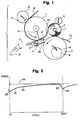
- FIG. 1 a typical three drum cradle is illustrated which is suitably mounted on a frame F -- only part of which is illustrated in the lower central portion of FIG. 1.
- a pair of side frames (not shown) are provided which support the various drums and other rotatable members in rotatable fashion.
- the symbol W designates a web which is to be rewound from a parent roll (not shown) into a log L -- see the right central portion of FIG. 1.
- the log L has a diameter of the normally experienced toilet tissue or toweling rolls and consists of a number of layers of convolutely wound web W on a central core C.
- the core C in position C' is shown in pre-wound condition and corresponds to the beginning of the winding cycle.
- the log L is discharged along a ramp 10 for further processing -- usually sawing the same transversely into retail size roll lengths.
- the numeral 11 designates a bedroll on which the web W is partially wrapped and also constitutes the first winding drum.
- a knife roll 12 Arranged on the frame F on the side of the web opposite to the first winding drum 11 is a knife roll 12 equipped with a knife 13 for coaction with the bedroll 11 in order to transversely sever the web incident to the end of one winding cycle and the beginning of another winding cycle.
- the web W has a leading edge which is engaged by a vacuum port 14 (in this showing) to make sure that the leading edge of the now-severed web conforms to the periphery of the first winding drum 11 until transfer occurs to the glue equipped core C'.
- This second or lower winding drum 17 is mounted for movement at least away from the first winding drum 11 although the invention may be practiced to advantage with the center distances between the two drums being constant, i.e., the spacing between the drums 11 and 17 remaining constant. In the event movement is employed, it may either be a pivotal or reciprocating type movement as indicated by the double ended arrows 18 or in a closed loop shown in dotted line as at 19.
- suitable means are provided on the frame F and they may be advantageously of the type seen in co-owned Patent US-A-4,848,195. Completing the previously referred to three-drum cradle is a rider drum R.
- the web W is unwound from a source such as a jumbo parent roll and proceeds as illustrated on the surface of the rotating first drum 11, being transversely severed by the knife 13 on the knife roll 12. Thereafter, the leading edge of the now-severed web encounters the core C' and is wound thereon first as the core C' travels to the right on stationary plate 16 and thereafter on the surface of the winding drum 17.
- the speed of the second winding drum 17 is relatively slow in comparison with the constant speed 20 of the first winding drum 11.
- This lower drum speed 21 increases fairly rapidly over the initial part of the wind so as to propel the now partially wound roll through the space 22 between the first and second winding drums 11, 17.
- the speed of the second winding drum follows a path designated 23 which approaches but does not precisely equal the surface speed of the first winding roll and which increases as a function of the increasing diameter of the partially wound roll.
- the speed of the second winding roll drips as rapidly as possible so as at 24 so as to be ready to start another winding cycle as at 25 (see both ends of the plot of Fig. 2).
Abstract
Description
Claims (6)
- A surface rewinder for convolutely wound web rolls comprising a frame (F), a three drum cradle rotatably mounted on said frame and including spaced apart first and second winding drums (11, 17) and a rider drum (R), means on said frame (F) for rotating each of said drums (11, 17), core introducing means (15) on said frame (F) for moving a core (C) toward the space (22) between said first and second winding drum, control means operably associated with said frame for changing the rotational speed of said second winding drum (17) such that the speed of the second drum is decreased just prior to the beginning of each winding cycle characterized in that the control means is also capable of substantially eliminating slippage between said second winding drum (17) and a web roll being wound on said core (C) by providing a speed profile in said second winding drum (17) wherein the speed of said second drum is decreased just prior to the beginning of each winding cycle (25) to advance a partially wound roll through said space (22) and thereafter increased as a function of the increasing diameter of said partially wound roll (L).
- The rewinder of claim 1 in which said frame (F) is equipped with means for moving said second winding drum (17) during each cycle of winding.
- The rewinder of claim 2 in which said means moves said second winding drum through a closed path (19).
- The rewinder of claim 1 in which said second winding roll (17) has a cylindrical outer surface, said surface being equipped with non-slip material.
- A method for convolutely winding web rolls comprising providing a three drum cradle rotatably mounted on a frame (F) and including spaced apart first and second winding drums (11, 17) and a rider drum (R), rotating each of said drums, moving a core (C) toward the space (22) between said first and second winding drums (11, 17), and controlling the rotational speed of said second winding drum (17) such that the speed is decreased just prior to the beginning of each winding cycle characterized in that the speed of the second winding drum (17) is controlled to substantially eliminate slippage between said second winding drum (17) and a web roll (L) being wound on said core (C) by providing a speed profile in said second winding drum (17) wherein the speed of said second drum is decreased (25 - Fig 2) just prior to the beginning of each winding cycle to advance a partially wound roll through said space (22) and thereafter increased as a function of the increasing diameter of said partially wound roll (L).
- The method of claim 5 in which said second winding drum (17) is moved during each winding cycle to change the space between said first and second winding drums (11, 17).
Applications Claiming Priority (2)
| Application Number | Priority Date | Filing Date | Title |
|---|---|---|---|
| US08/019,074 US5370335A (en) | 1993-02-18 | 1993-02-18 | Surface rewinder and method |
| US19074 | 1993-02-18 |
Publications (3)
| Publication Number | Publication Date |
|---|---|
| EP0620176A2 EP0620176A2 (en) | 1994-10-19 |
| EP0620176A3 EP0620176A3 (en) | 1995-02-15 |
| EP0620176B1 true EP0620176B1 (en) | 1998-04-01 |
Family
ID=21791279
Family Applications (1)
| Application Number | Title | Priority Date | Filing Date |
|---|---|---|---|
| EP93118681A Expired - Lifetime EP0620176B1 (en) | 1993-02-18 | 1993-11-19 | Surface rewinder and method of operation |
Country Status (9)
| Country | Link |
|---|---|
| US (1) | US5370335A (en) |
| EP (1) | EP0620176B1 (en) |
| JP (1) | JP3433837B2 (en) |
| AT (1) | ATE164562T1 (en) |
| AU (1) | AU5077593A (en) |
| BR (1) | BR9304869A (en) |
| CA (1) | CA2102938A1 (en) |
| DE (1) | DE69317759T2 (en) |
| MX (1) | MX9307244A (en) |
Cited By (1)
| Publication number | Priority date | Publication date | Assignee | Title |
|---|---|---|---|---|
| US7942363B2 (en) | 2004-03-18 | 2011-05-17 | Fabio Perini S.P.A. | Combined peripheral and central rewinding machine |
Families Citing this family (35)
| Publication number | Priority date | Publication date | Assignee | Title |
|---|---|---|---|---|
| IL106327A (en) * | 1992-07-21 | 1997-06-10 | Perini Fabio Spa | Machine and method for the formation of coreless rolls of web material |
| US5505405A (en) * | 1993-02-18 | 1996-04-09 | Paper Converting Machine Company | Surface rewinder and method having minimal drum to web slippage |
| IT1278644B1 (en) * | 1995-04-14 | 1997-11-27 | Perini Fabio Spa | REWINDING MACHINE FOR ROLLS OF TAPE MATERIAL, WITH CONTROL OF THE INTRODUCTION OF THE WINDING CORE |
| US5772149A (en) * | 1996-09-18 | 1998-06-30 | C. G. Bretting Manufacturing Company, Inc. | Winding control finger surface rewinder |
| US5820064A (en) * | 1997-03-11 | 1998-10-13 | C.G. Bretting Manufacturing Company, Inc. | Winding control finger surface rewinder with core insert finger |
| US6000657A (en) * | 1996-09-18 | 1999-12-14 | C.G. Bretting Manufacturing Company, Inc. | Winding control finger surface rewinder with core insert finger |
| US5839688A (en) * | 1997-08-08 | 1998-11-24 | Paper Converting Machine Co. | Method and apparatus for producing a roll of bathroom tissue or kitchen toweling with a pattern being repeated between each pair of transverse perforations |
| US6056229A (en) | 1998-12-03 | 2000-05-02 | Paper Converting Machine Co. | Surface winder with pinch cutoff |
| US6010090A (en) * | 1998-12-11 | 2000-01-04 | Paper Converting Machine Co. | Method of perforating a web |
| US6659387B2 (en) | 2000-11-07 | 2003-12-09 | Paper Converting Machine Co. | Peripheral rewinding machine and method for producing logs of web material |
| US6422501B1 (en) | 2000-11-27 | 2002-07-23 | Paper Converting Machine Company | Core infeed apparatus for winder |
| IT249984Y1 (en) * | 2000-12-27 | 2003-07-07 | Gambini Giovanni | REWINDING DEVICE TO FORM A PAPER ROLL IN A REWINDER MACHINE |
| DE10119460B4 (en) * | 2001-04-17 | 2004-09-16 | Sca Hygiene Products Gmbh | Method and device for winding a material web onto a sleeve serving as a winding core |
| US7000864B2 (en) | 2002-06-10 | 2006-02-21 | The Procter & Gamble Company | Consumer product winding control and adjustment |
| US7222813B2 (en) * | 2005-03-16 | 2007-05-29 | Chan Li Machinery Co., Ltd. | Multiprocessing apparatus for forming logs of web material and log manufacture process |
| US7472861B2 (en) * | 2005-06-20 | 2009-01-06 | The Procter & Gamble Company | Method for a surface rewind system |
| US7392961B2 (en) * | 2005-08-31 | 2008-07-01 | The Procter & Gamble Company | Hybrid winder |
| US7455260B2 (en) * | 2005-08-31 | 2008-11-25 | The Procter & Gamble Company | Process for winding a web material |
| US7546970B2 (en) * | 2005-11-04 | 2009-06-16 | The Procter & Gamble Company | Process for winding a web material |
| US8800908B2 (en) * | 2005-11-04 | 2014-08-12 | The Procter & Gamble Company | Rewind system |
| US8459586B2 (en) * | 2006-03-17 | 2013-06-11 | The Procter & Gamble Company | Process for rewinding a web material |
| US7559503B2 (en) * | 2006-03-17 | 2009-07-14 | The Procter & Gamble Company | Apparatus for rewinding web materials |
| US8157200B2 (en) * | 2009-07-24 | 2012-04-17 | The Procter & Gamble Company | Process for winding a web material |
| US8162251B2 (en) * | 2009-07-24 | 2012-04-24 | The Procter & Gamble Company | Hybrid winder |
| US9284147B2 (en) | 2012-09-21 | 2016-03-15 | Paper Converting Machine Company | Method and apparatus for producing coreless rolls of paper |
| US9376281B2 (en) | 2013-09-09 | 2016-06-28 | The Procter & Gamble Company | Cam-controlled core inserter for a surface winder |
| JP6522169B2 (en) * | 2015-06-19 | 2019-05-29 | フューチュラ エス ピー エー | Paper log manufacturing rewinder |
| US9809417B2 (en) | 2015-08-14 | 2017-11-07 | The Procter & Gamble Company | Surface winder |
| US10442649B2 (en) | 2016-03-04 | 2019-10-15 | The Procter & Gamble Company | Surface winder for producing logs of convolutely wound web materials |
| US10427902B2 (en) | 2016-03-04 | 2019-10-01 | The Procter & Gamble Company | Enhanced introductory portion for a surface winder |
| US10427903B2 (en) | 2016-03-04 | 2019-10-01 | The Procter & Gamble Company | Leading edge device for a surface winder |
| EP4116245A1 (en) | 2017-11-29 | 2023-01-11 | Paper Converting Machine Company | Surface rewinder with center assist and belt and winding drum forming a winding nest |
| US11247863B2 (en) | 2018-11-27 | 2022-02-15 | Paper Converting Machine Company | Flexible drive and core engagement members for a rewinding machine |
| US11208282B2 (en) * | 2018-12-06 | 2021-12-28 | Paper Converting Machine Company | Method of initiating a web winding process in a web winding system |
| US11383946B2 (en) | 2019-05-13 | 2022-07-12 | Paper Converting Machine Company | Solid roll product formed from surface rewinder with belt and winding drum forming a winding nest |
Family Cites Families (16)
| Publication number | Priority date | Publication date | Assignee | Title |
|---|---|---|---|---|
| US2901191A (en) * | 1957-05-06 | 1959-08-25 | Black Clawson Co | Paper machinery |
| US3009666A (en) * | 1958-10-31 | 1961-11-21 | Samuel M Langston Co | Roll density control for slitter winders |
| DE2739515C3 (en) * | 1977-09-02 | 1981-04-16 | Jagenberg-Werke AG, 4000 Düsseldorf | Device for winding up a web of material, in particular made of paper |
| DE2751829A1 (en) * | 1977-11-19 | 1979-05-23 | Hobema Maschf Hermann | Paper roll winding machine - has winding rollers carried around periphery of support roller by swinging arms |
| IT1165998B (en) * | 1979-09-21 | 1987-04-29 | Fabio Perini | CONTINUOUS WRAPPING DEVICE FOR PAPER TAPES AND MORE IN THE PRODUCTION OF TOILET PAPER AND SIMILAR MANUFACTURES |
| SE450703B (en) * | 1982-04-01 | 1987-07-20 | Asea Ab | SET FOR CHECKING IT IN A PARALLELED PAPER ROLLED MATERIAL TENSION |
| US4962897A (en) * | 1986-04-01 | 1990-10-16 | Paper Converting Machine Company | Web winding machine and method |
| JPS63258350A (en) * | 1987-04-15 | 1988-10-25 | Tokushichi Yamazaki | Manufacture of toilet paper in roll |
| FI81551C (en) * | 1987-05-20 | 1990-11-12 | Valmet Paper Machinery Inc | PROCEDURE FOR THE MEASUREMENT OF ROLLING OF BANA. |
| US4909452A (en) * | 1988-02-29 | 1990-03-20 | Paper Converting Machine Company | Surface winder and method |
| US4828195A (en) * | 1988-02-29 | 1989-05-09 | Paper Converting Machine Company | Surface winder and method |
| IT1233170B (en) * | 1989-03-09 | 1992-03-14 | Perini Finanziaria Spa | REWINDING MACHINE TO FORM PAPER ROLLS OR OTHER |
| IT1234455B (en) * | 1989-06-08 | 1992-05-18 | Perini Navi Spa | EQUIPMENT FOR FORMING ROLLS THAT IS STICKS OF MATERIAL TAPED ON A WINDING SOUL |
| IT1246226B (en) * | 1991-01-09 | 1994-11-16 | Consani Alberto Spa | REFINEMENTS FOR REWINDERS FOR SHEET MATERIALS |
| US5104055A (en) * | 1991-02-05 | 1992-04-14 | Paper Converting Machine Company | Apparatus and method for making convolutely wound logs |
| JPH04327455A (en) * | 1991-04-25 | 1992-11-17 | Toshiba Corp | Winding control device for winding machine |
-
1993
- 1993-02-18 US US08/019,074 patent/US5370335A/en not_active Expired - Lifetime
- 1993-11-12 CA CA002102938A patent/CA2102938A1/en not_active Abandoned
- 1993-11-18 AU AU50775/93A patent/AU5077593A/en not_active Abandoned
- 1993-11-19 DE DE69317759T patent/DE69317759T2/en not_active Expired - Fee Related
- 1993-11-19 EP EP93118681A patent/EP0620176B1/en not_active Expired - Lifetime
- 1993-11-19 MX MX9307244A patent/MX9307244A/en not_active IP Right Cessation
- 1993-11-19 AT AT93118681T patent/ATE164562T1/en not_active IP Right Cessation
- 1993-11-29 BR BR9304869A patent/BR9304869A/en not_active IP Right Cessation
-
1994
- 1994-02-18 JP JP04498494A patent/JP3433837B2/en not_active Expired - Fee Related
Cited By (1)
| Publication number | Priority date | Publication date | Assignee | Title |
|---|---|---|---|---|
| US7942363B2 (en) | 2004-03-18 | 2011-05-17 | Fabio Perini S.P.A. | Combined peripheral and central rewinding machine |
Also Published As
| Publication number | Publication date |
|---|---|
| BR9304869A (en) | 1994-09-27 |
| JP3433837B2 (en) | 2003-08-04 |
| MX9307244A (en) | 1994-08-31 |
| DE69317759T2 (en) | 1998-07-30 |
| US5370335A (en) | 1994-12-06 |
| CA2102938A1 (en) | 1994-08-19 |
| JPH07117903A (en) | 1995-05-09 |
| AU5077593A (en) | 1994-08-25 |
| EP0620176A2 (en) | 1994-10-19 |
| ATE164562T1 (en) | 1998-04-15 |
| EP0620176A3 (en) | 1995-02-15 |
| DE69317759D1 (en) | 1998-05-07 |
Similar Documents
| Publication | Publication Date | Title |
|---|---|---|
| EP0620176B1 (en) | Surface rewinder and method of operation | |
| EP0909735B1 (en) | Surface rewinder and method having minimal drum to web slippage | |
| EP0580561B1 (en) | Machine and method for the formation of coreless logs of web material | |
| EP0635444B1 (en) | Surface winder with recycled mandrels and method | |
| EP0785157B1 (en) | Method and apparatus for convolute winding | |
| US8262011B2 (en) | Center/surface rewinder and winder | |
| CA2115497C (en) | Rewinding machine for coreless winding of a log of web material with a surface for supporting the log in the process of winding | |
| US5402960A (en) | Coreless surface winder and method | |
| US5346150A (en) | Tail gap winder | |
| US5695149A (en) | Carrier-roller winder | |
| US3365141A (en) | Cut-off knife for winders and unwinders | |
| US6659387B2 (en) | Peripheral rewinding machine and method for producing logs of web material | |
| EP1173377B1 (en) | Single station continuous log roll winder | |
| CA2018289C (en) | Paper-making machine reeling operation | |
| US20030146334A1 (en) | Winding method and apparatus | |
| EP0616965B1 (en) | Coreless winding method | |
| EP1205414B1 (en) | Peripheral rewinding machine and method for producing logs of web material | |
| CA2100797C (en) | Machine and method for the formation of coreless logs of web material | |
| EP3204321B1 (en) | Short strain cutoff device |
Legal Events
| Date | Code | Title | Description |
|---|---|---|---|
| PUAI | Public reference made under article 153(3) epc to a published international application that has entered the european phase |
Free format text: ORIGINAL CODE: 0009012 |
|
| AK | Designated contracting states |
Kind code of ref document: A2 Designated state(s): AT BE CH DE FR GB GR IT LI SE |
|
| PUAL | Search report despatched |
Free format text: ORIGINAL CODE: 0009013 |
|
| AK | Designated contracting states |
Kind code of ref document: A3 Designated state(s): AT BE CH DE FR GB GR IT LI SE |
|
| 17P | Request for examination filed |
Effective date: 19950316 |
|
| 17Q | First examination report despatched |
Effective date: 19960902 |
|
| GRAG | Despatch of communication of intention to grant |
Free format text: ORIGINAL CODE: EPIDOS AGRA |
|
| GRAG | Despatch of communication of intention to grant |
Free format text: ORIGINAL CODE: EPIDOS AGRA |
|
| GRAH | Despatch of communication of intention to grant a patent |
Free format text: ORIGINAL CODE: EPIDOS IGRA |
|
| GRAH | Despatch of communication of intention to grant a patent |
Free format text: ORIGINAL CODE: EPIDOS IGRA |
|
| GRAA | (expected) grant |
Free format text: ORIGINAL CODE: 0009210 |
|
| AK | Designated contracting states |
Kind code of ref document: B1 Designated state(s): AT BE CH DE FR GB GR IT LI SE |
|
| PG25 | Lapsed in a contracting state [announced via postgrant information from national office to epo] |
Ref country code: LI Free format text: LAPSE BECAUSE OF FAILURE TO SUBMIT A TRANSLATION OF THE DESCRIPTION OR TO PAY THE FEE WITHIN THE PRESCRIBED TIME-LIMIT Effective date: 19980401 Ref country code: GR Free format text: LAPSE BECAUSE OF NON-PAYMENT OF DUE FEES Effective date: 19980401 Ref country code: CH Free format text: LAPSE BECAUSE OF FAILURE TO SUBMIT A TRANSLATION OF THE DESCRIPTION OR TO PAY THE FEE WITHIN THE PRESCRIBED TIME-LIMIT Effective date: 19980401 Ref country code: BE Free format text: LAPSE BECAUSE OF FAILURE TO SUBMIT A TRANSLATION OF THE DESCRIPTION OR TO PAY THE FEE WITHIN THE PRESCRIBED TIME-LIMIT Effective date: 19980401 Ref country code: AT Free format text: LAPSE BECAUSE OF FAILURE TO SUBMIT A TRANSLATION OF THE DESCRIPTION OR TO PAY THE FEE WITHIN THE PRESCRIBED TIME-LIMIT Effective date: 19980401 |
|
| REF | Corresponds to: |
Ref document number: 164562 Country of ref document: AT Date of ref document: 19980415 Kind code of ref document: T |
|
| REG | Reference to a national code |
Ref country code: CH Ref legal event code: EP |
|
| REF | Corresponds to: |
Ref document number: 69317759 Country of ref document: DE Date of ref document: 19980507 |
|
| ITF | It: translation for a ep patent filed |
Owner name: MODIANO & ASSOCIATI S.R.L. |
|
| ET | Fr: translation filed | ||
| REG | Reference to a national code |
Ref country code: CH Ref legal event code: PL |
|
| PLBE | No opposition filed within time limit |
Free format text: ORIGINAL CODE: 0009261 |
|
| STAA | Information on the status of an ep patent application or granted ep patent |
Free format text: STATUS: NO OPPOSITION FILED WITHIN TIME LIMIT |
|
| 26N | No opposition filed | ||
| REG | Reference to a national code |
Ref country code: GB Ref legal event code: IF02 |
|
| PGFP | Annual fee paid to national office [announced via postgrant information from national office to epo] |
Ref country code: FR Payment date: 20051021 Year of fee payment: 13 |
|
| PGFP | Annual fee paid to national office [announced via postgrant information from national office to epo] |
Ref country code: GB Payment date: 20051024 Year of fee payment: 13 Ref country code: DE Payment date: 20051024 Year of fee payment: 13 |
|
| PGFP | Annual fee paid to national office [announced via postgrant information from national office to epo] |
Ref country code: SE Payment date: 20051025 Year of fee payment: 13 |
|
| PG25 | Lapsed in a contracting state [announced via postgrant information from national office to epo] |
Ref country code: SE Free format text: LAPSE BECAUSE OF NON-PAYMENT OF DUE FEES Effective date: 20061120 |
|
| PG25 | Lapsed in a contracting state [announced via postgrant information from national office to epo] |
Ref country code: DE Free format text: LAPSE BECAUSE OF NON-PAYMENT OF DUE FEES Effective date: 20070601 |
|
| EUG | Se: european patent has lapsed | ||
| GBPC | Gb: european patent ceased through non-payment of renewal fee |
Effective date: 20061119 |
|
| REG | Reference to a national code |
Ref country code: FR Ref legal event code: ST Effective date: 20070731 |
|
| PG25 | Lapsed in a contracting state [announced via postgrant information from national office to epo] |
Ref country code: GB Free format text: LAPSE BECAUSE OF NON-PAYMENT OF DUE FEES Effective date: 20061119 |
|
| PG25 | Lapsed in a contracting state [announced via postgrant information from national office to epo] |
Ref country code: FR Free format text: LAPSE BECAUSE OF NON-PAYMENT OF DUE FEES Effective date: 20061130 |
|
| PGFP | Annual fee paid to national office [announced via postgrant information from national office to epo] |
Ref country code: IT Payment date: 20121113 Year of fee payment: 20 |