EP0626989B1 - Absorption process for ethylene and hydrogen recovery - Google Patents
Absorption process for ethylene and hydrogen recovery Download PDFInfo
- Publication number
- EP0626989B1 EP0626989B1 EP92922526A EP92922526A EP0626989B1 EP 0626989 B1 EP0626989 B1 EP 0626989B1 EP 92922526 A EP92922526 A EP 92922526A EP 92922526 A EP92922526 A EP 92922526A EP 0626989 B1 EP0626989 B1 EP 0626989B1
- Authority
- EP
- European Patent Office
- Prior art keywords
- stream
- column
- solvent
- ethylene
- gas stream
- Prior art date
- Legal status (The legal status is an assumption and is not a legal conclusion. Google has not performed a legal analysis and makes no representation as to the accuracy of the status listed.)
- Expired - Lifetime
Links
Images


Classifications
-
- C—CHEMISTRY; METALLURGY
- C10—PETROLEUM, GAS OR COKE INDUSTRIES; TECHNICAL GASES CONTAINING CARBON MONOXIDE; FUELS; LUBRICANTS; PEAT
- C10G—CRACKING HYDROCARBON OILS; PRODUCTION OF LIQUID HYDROCARBON MIXTURES, e.g. BY DESTRUCTIVE HYDROGENATION, OLIGOMERISATION, POLYMERISATION; RECOVERY OF HYDROCARBON OILS FROM OIL-SHALE, OIL-SAND, OR GASES; REFINING MIXTURES MAINLY CONSISTING OF HYDROCARBONS; REFORMING OF NAPHTHA; MINERAL WAXES
- C10G70/00—Working-up undefined normally gaseous mixtures obtained by processes covered by groups C10G9/00, C10G11/00, C10G15/00, C10G47/00, C10G51/00
- C10G70/04—Working-up undefined normally gaseous mixtures obtained by processes covered by groups C10G9/00, C10G11/00, C10G15/00, C10G47/00, C10G51/00 by physical processes
- C10G70/041—Working-up undefined normally gaseous mixtures obtained by processes covered by groups C10G9/00, C10G11/00, C10G15/00, C10G47/00, C10G51/00 by physical processes by distillation
-
- C—CHEMISTRY; METALLURGY
- C10—PETROLEUM, GAS OR COKE INDUSTRIES; TECHNICAL GASES CONTAINING CARBON MONOXIDE; FUELS; LUBRICANTS; PEAT
- C10G—CRACKING HYDROCARBON OILS; PRODUCTION OF LIQUID HYDROCARBON MIXTURES, e.g. BY DESTRUCTIVE HYDROGENATION, OLIGOMERISATION, POLYMERISATION; RECOVERY OF HYDROCARBON OILS FROM OIL-SHALE, OIL-SAND, OR GASES; REFINING MIXTURES MAINLY CONSISTING OF HYDROCARBONS; REFORMING OF NAPHTHA; MINERAL WAXES
- C10G5/00—Recovery of liquid hydrocarbon mixtures from gases, e.g. natural gas
- C10G5/04—Recovery of liquid hydrocarbon mixtures from gases, e.g. natural gas with liquid absorbents
-
- C—CHEMISTRY; METALLURGY
- C10—PETROLEUM, GAS OR COKE INDUSTRIES; TECHNICAL GASES CONTAINING CARBON MONOXIDE; FUELS; LUBRICANTS; PEAT
- C10G—CRACKING HYDROCARBON OILS; PRODUCTION OF LIQUID HYDROCARBON MIXTURES, e.g. BY DESTRUCTIVE HYDROGENATION, OLIGOMERISATION, POLYMERISATION; RECOVERY OF HYDROCARBON OILS FROM OIL-SHALE, OIL-SAND, OR GASES; REFINING MIXTURES MAINLY CONSISTING OF HYDROCARBONS; REFORMING OF NAPHTHA; MINERAL WAXES
- C10G70/00—Working-up undefined normally gaseous mixtures obtained by processes covered by groups C10G9/00, C10G11/00, C10G15/00, C10G47/00, C10G51/00
- C10G70/04—Working-up undefined normally gaseous mixtures obtained by processes covered by groups C10G9/00, C10G11/00, C10G15/00, C10G47/00, C10G51/00 by physical processes
- C10G70/06—Working-up undefined normally gaseous mixtures obtained by processes covered by groups C10G9/00, C10G11/00, C10G15/00, C10G47/00, C10G51/00 by physical processes by gas-liquid contact
-
- Y—GENERAL TAGGING OF NEW TECHNOLOGICAL DEVELOPMENTS; GENERAL TAGGING OF CROSS-SECTIONAL TECHNOLOGIES SPANNING OVER SEVERAL SECTIONS OF THE IPC; TECHNICAL SUBJECTS COVERED BY FORMER USPC CROSS-REFERENCE ART COLLECTIONS [XRACs] AND DIGESTS
- Y02—TECHNOLOGIES OR APPLICATIONS FOR MITIGATION OR ADAPTATION AGAINST CLIMATE CHANGE
- Y02P—CLIMATE CHANGE MITIGATION TECHNOLOGIES IN THE PRODUCTION OR PROCESSING OF GOODS
- Y02P20/00—Technologies relating to chemical industry
- Y02P20/10—Process efficiency
- Y02P20/129—Energy recovery, e.g. by cogeneration, H2recovery or pressure recovery turbines
Definitions
- This invention relates to treating hydrocarbon gases, such as cracked gases and refinery off-gases for recovering one or more desirable components.
- Thermal cracking of hydrocarbon feedstocks in pyrolysis furnaces for production of ethylene has been an established technology since the 1940's.
- the pyrolysis furnace gases were cooled, compressed, sweetened, dried and sent to the recovery section of an ethylene plant in which the first fractionation column was a front-end demethanizer operating at about -150°C.
- the demethanizer bottoms were fed to a deethanizer, and the demethanizer overhead, rich in hydrogen, was fed to a cryogenic unit which recovered additional ethylene from the fuel gas stream.
- a back-end acetylene removal system such as a series of two acetylene reactors, was typically located between the deethanizer and the C2 splitter.
- a Methyl Acetylene and Propadiene Reactor was located between the depropanizer and the C3 splitter. This arrangement caused the production of large amounts of green oil, a polymer formed from olefins and diolefins, which was likely to freeze in the C2 splitter or accumulate in the ethane vaporizer.
- green oil By processing overhead gases from a heat-pumped deethanizer or depropanizer, which is coupled with a front-end catalytic acetylene hydrogenation reactor, the green oil problem is eliminated.
- U. S. 4,832,718 of Y. R. Mehra teaches a method for hydrogen purification by countercurrently and successively extracting an olefins containing gas stream, at a pressure no greater than 3,448 kPa, in an ethylene extractor column with a solvent slip stream from at least one flashing stage and then with lean solvent in a methane extractor column.
- U. S. 5,019,143 of Y. R. Mehra describes a continuous process for contacting a hydrogen off-gas stream, at any pressure, in a demethanizing-absorber column, having at least one reboiler, with a main stream of stripped physical solvent and then with a cleanup stream of lean solvent.
- Hydrogen is present in large quantities in thermally or catalytically cracked gas streams or in refinery off-gases and is commonly associated with olefins, such as ethylene and propylene.
- these gases generally comprise methane, carbon monoxide, carbon dioxide, ethylene, ethane, acetylene, methyl acetylene, propadiene, propylene, propane, butadienes, butenes, butanes, C 5 's, C 6 -C 8 non-aromatics, benzene, toluene, xylenes, ethyl benzene, styrene, C 9 -204°C gasoline, 204+°C fuel oil, and water.
- the inventors of the KTI/AET ethylene recovery process of this invention described the invention as incorporating a front-end heat-pumped depropanizer, followed by a fourth-stage compressor, a front-end selective catalytic acetylene hydrogenation reactor system, and a drying stage before feeding to an absorber-stripper column which absorbs the C 2 's and the C3's and produces an overhead which is fed to a small auto refrigerated (by means of an expander) demethanizer where essentially all the C 2 's are recovered.
- the rich solvent is fed to a solvent regenerator where the demethanized C 2 's and C 3 's are recovered as overhead product and the lean solvent is produced and returned to the absorber-stripper after heat recovery. No ethylene refrigeration is required.
- the C 2 's and C 3 's are further separated in a conventional deethanizer to produce a C 2 fraction and a C 3 fraction that are then processed in their respective super-fractionators to produce polymer grade ethylene and propylene products. Ethane and propane leaving their respective super-fractionators as bottom products are recycled and cracked to extinction in the pyrolysis furnaces.
- the present invention provides a process for recovering ethylene from a hydrocarbon gas stream as defined in claim 1.
- This invention can begin with respect to ethylene recovery by treating a cooled, sweetened, and compressed hydrocarbon gas stream, containing hydrogen, methane, carbon monoxide, ethylene, ethane, acetylene, and the C 3 and heavier hydrocarbons characteristic of an ethylene plant cracked gas stream and/or a refinery off-gas stream, by passing it through a heat-pumped depropanizer column which is coupled with a front-end selective catalytic acetylene hydrogenation reactor system to produce a C 3 -and-lighter overhead stream that is fed to the demethanizing absorber column as the feedstock gas stream.
- treating can begin by passing the cooled, sweetened, and compressed hydrocarbon gas stream through a heat-pumped deethanizer column which is coupled with a front-end selective catalytic acetylene hydrogenation reactor system to produce a C 2 -and-lighter overhead stream that is fed to the demethanizing absorber column as the feedstock gas stream.
- the process of this invention can be applied to all feedstocks for any conventional ethylene plant having a front-end deethanizer or a front-end depropanizer, but as described hereinafter, it is exemplified by using a full range naphtha feedstock for a plant with a front-end depropanizer.
- the naphtha feedstock is vaporized and sent to the pyrolysis furnaces, and the furnace effluent is indirectly quenched in transfer-line exchangers before direct quench in the oil quench tower.
- Fuel oil fractions are produced from the quench system.
- Heat recovery from the hot furnace effluent is accomplished in the oil quench system by heat exchange with other process loads and generation of dilution steam.
- the oil quench tower overhead is cooled further in the water quench system where the dilution steam is condensed.
- Heat is recovered from the circulating quench water by heat exchange with other process loads, especially the regeneration column reboiler load, so that there is an energy synergism within the overall system.
- the cooled water quench tower overhead is compressed in three stages to an optimum pressure primarily governed by the operating pressure of the front-end depropanizer.
- acid gases are removed by a combination of amine and caustic systems. The acid gas-free cracked gas is then dried before entering the fractionation section of the plant.
- a low-pressure debutanizing stripper column is located in the compression train to remove C5 and heavier fractions from the cracked gas. No high-pressure stripper column is required in the compression train.
- the process of this invention utilizes a front-end heat pumped depropanizer system coupled with a front-end selective catalytic acetylene hydrogenation reactor system.
- the front-end heat pumped depropanizer permits fractionation at low pressure and condensation at high pressure. Fouling is minimized when the depropanizer is operated at low pressure.
- the energy for heat pumping of the depropanizer is provided by the fourth stage of the cracked gas compressor.
- acetylene is selectively hydrogenated to ethylene in the front-end reactor system.
- heavier C 3 and C 4 acetylenes and diolefins contained in the depropanizer overhead are selectively hydrogenated to their respective olefins, resulting in overall olefin gains across the reactor system. No green oil is formed across this reactor system.
- the acetylene-free C3-and-lighter portion of the cracked gas leaves the reactor and is dried in a dehydrator to remove trace quantities of moisture.
- This C3-and-lighter fraction leaves the depropanizer reflux drum and enters the solvent extraction system for recovery of C2-plus hydrocarbons.
- the C3-and-lighter fraction is fed to the demethanizing absorber column.
- the C2's and C3's are absorbed by the solvent while methane and lighter components, together with some ethylene, leave the top of the demethanizing absorber column.
- This overhead stream is fed to a small auto refrigerated recovery unit wherein essentially all the C2's are recovered. Additionally, any solvent present in the demethanizing absorber column overhead is recovered by a means not shown in Figures 1, 2 and 3 and is returned to the demethanizing absorber column.
- the expansion recovery system is auto refrigerated by means of cross exchanging various streams and utilizing turbo expanders and/or pressure let down valves thereby requiring no external refrigeration below -55°C.
- the rich solvent from the bottom of the demethanizing absorber column is fed to a solvent regenerator column where the demethanized C2's and C3's are recovered as overhead product.
- the lean solvent is returned to the demethanizing absorber column after heat recovery.
- the C2's and C3's are further separated in a conventional deethanizer column to produce a C2 and a C3 fraction. These two fractions are then processed in their respective super-fractionators to produce polymer grade ethylene and propylene products. Ethane and propane leaving their respective super-fractionators (i.e., C 2 and C 3 splitter columns) as bottom products are recycled and cracked to extinction in the pyrolysis furnaces. Back-end acetylene hydrogenation reactors are eliminated.
- the C4-plus fraction leaving the bottom of the heat pumped deethanizer column or heat pumped depropanizer column is fed to a conventional debutanizer column to produce a C4 mix as overhead product.
- the bottom product from the debutanizer column is combined with the bottoms from the low pressure stripper column in the compression train and sent to the pyrolysis gasoline hydrotreater.
- External refrigeration for the ethylene recovery process of this invention is supplied only by a propylene refrigeration compressor. No ethylene refrigeration is required by the ethylene recovery process of this invention. It should be understood that for the process of this invention any refrigerant capable of providing external refrigeration no lower than -55°C is useful.
- This invention is characterized by selecting the hydrocarbon solvent from the group consisting of paraffinic hydrocarbons having 4 to 10 carbon atoms, naphthenic hydrocarbons having 4 to 10 carbon atoms, aromatic hydrocarbons selected from the group consisting of benzene, toluene, C 8 -C 10 aromatic compounds having methyl, ethyl or propyl aliphatic groups specifically o-xylene, m-xylene, p-xylene, hemimellitene, pseudocumene, mesitylene, cumene, o-ethyltoluene, m-ethyltoluene, p-ethyltoluene, n-propylbenzene, isopropylbenzene, indane, durene, isodurene, prehnitene, crude xylenes, toluene transalkylation reaction effluents, extracted C 9 naphtha reformates, C 9 heart cuts
- the invention is further characterized by intercooling and reboiling a demethanizing absorber column, to which a feedstock stream of the hydrocarbon gases is fed, and adjusting the lean solvent circulation rate thereto to produce an overhead gas stream and to absorb 75% to 99% of the ethylene present in the hydrocarbon gas stream into a bottom rich solvent stream that is fed to a solvent regenerator column that produces an overhead hydrocarbon stream of ethylene and heavier hydrocarbons and a lean solvent stream.
- the invention is additionally characterized by feeding the overhead gas stream to an auto refrigerated recovery unit to produce a fuel gas stream containing as low as 0.1% of the ethylene present in the hydrocarbon gas stream, to recover 1% to 25% of the ethylene present in the feedstock gas stream as a component of a C 2 -plus stream, and to recover excess solvent present in the overhead gas stream and then recycling the excess solvent to the demethanizing absorber column.
- the overhead hydrocarbon stream of ethylene and heavier hydrocarbons is combined with the C 2 -plus stream to produce a combined ethylene-rich stream that is fed to a deethanizer column to produce a bottom stream of propylene and heavier hydrocarbons and an overhead stream of ethylene and ethane.
- the overhead stream of ethylene and ethane is fed to a C 2 splitter column to produce a bottom stream of ethane and an overhead stream of ethylene that amounts to at least 99% of the ethylene in the hydrocarbon gas stream.
- This process for recovering ethylene is equally as useful for treating refinery off-gases as it is for treating cracked gases because its versatility enables it to be readily adapted to the great variety of such refinery feeds.
- cracked gases and refinery off-gases invariably contain hydrogen so that the feedstock gas stream fed to the demethanizing absorber column and the overhead gas stream from the demethanizing absorber column contain hydrogen in addition to ethylene and heavier hydrocarbons.
- the overhead gas stream is selectively split into a hydrogen portion stream and a fuel portion stream, the hydrogen portion stream being fed to a methane absorber column and the fuel portion stream being fed to the auto refrigerated recovery unit.
- the methane absorber column produces an overhead hydrogen stream, containing up to 50% of the hydrogen in the feedstock gas stream, and a bottom rich solvent stream which is fed to the demethanizing absorber column.
- the solvent When selectively recovering up to 50% of the hydrogen in the incoming feedstock gas stream, the solvent circulates as a single solvent loop, the circulation rate of which is determined by the C 2+ content of the feedstock gas stream.
- the overhead gas stream from the demethanizing absorber column is fed to a methane absorber column which produces a hydrogen stream, containing the 20% to 100% of the hydrogen in the feedstock gas stream, and a bottom rich solvent stream.
- the bottom rich solvent stream from the methane absorber column is selectively split into an absorber portion stream and a stripper portion stream, the absorber portion stream being fed to the demethanizing absorber column and the stripper portion stream being fed to a methane stripper column.
- the methane stripper column produces a bottom solvent stream which is recycled to the methane absorber column and an overhead stream which is fed to the auto refrigerated recovery unit.
- solvent circulates as two solvent loops that comprise a minor solvent loop circulating through the methane absorber column, the demethanizing absorber column, and the solvent regenerator column and a major solvent loop circulating through the methane stripper column and the methane absorber column, the circulation rate of the minor solvent circulation loop being determined by the C 2 -and-heavier content of the feedstock gas stream and the circulation rate of the major solvent circulation loop being determined by subtracting the flow rate of the bottom lean solvent stream produced by the solvent regenerator column from the total circulation rate required to absorb the contained methane in the overhead gas stream produced by the demethanizing absorber column.
- the bottom lean solvent stream from the methane absorption column is selectively split into a methane portion stream and an ethylene portion stream, the ethylene portion stream being fed to the demethanizing absorber column and the methane portion stream being fed to the methane stripper column.
- the cooled, sweetened, and compressed hydrocarbon gas stream is a FCC refinery off-gas stream that additionally contains nitrogen and nitrogen oxides
- auto refrigeration is provided through use of pressure let-down valves which in turn provide chilling to achieve the Joule-Thompson effect while limiting this chilling to a temperature no lower than -110°C whereby nitrogen oxides are prevented from condensing.
- the cooled, sweetened, and compressed feedstock gas stream contains hydrogen, methane, carbon monoxide, ethylene, ethane, and the C 3 and heavier hydrocarbons characteristic of a refinery off-gas stream but contains essentially no acetylene
- it may be treated by a heat-pumped deethanizer or a heat-pumped depropanizer column without catalytic hydrogenation to produce an overhead C 2 -and-lighter or C 3 -and-lighter stream respectively, that is fed to the demethanizing absorber column as the feedstock gas stream.
- Any solvent that is useful for absorbing hydrocarbons is suitable as the absorbent in the intercooled and reboiled demethanizing absorber and methane absorber columns of this invention.
- the process of this invention is equally as useful for treating refinery off-gases as it is for treating cracked gases because its versatility enables it to be readily adapted to the great variety of such refinery feeds.
- Some refinery off-gases for example, do not contain acetylene and can bypass the acetylene reactor, the dehydrator, and the chilling and phase separation unit.
- absorption is conventionally employed for a gas/solvent absorbing facility, but when it is utilized in the process of this invention with a preferential physical solvent, it is considered to be an "extractor".
- An absorber is also to be understood as an absorption column, and a stripper is to be understood as a distillation column.
- absorber-stripper and “demethanizing absorber” refer to the same equipment and that “expansion recovery” and “auto refrigerated recovery unit” refer to the same equipment.
- Figure 1 is a schematic flow diagram in which a demethanizing absorber receives gases from a heat-pumped depropanizer or a heat-pumped deethanizer and sends its overhead to a small auto refrigerated recovery unit which obviates essentially all losses of olefins and solvent.
- Figure 2 is a schematic flow diagram of the slip stream embodiment for recovering up to 50% of the hydrogen in the overhead gas stream from a front-end heat pumped deethanizer or depropanizer column or from a refinery off-gas stream.
- Figure 3 is a schematic flow diagram of the full stream embodiment for recovering 20% to 100% of the hydrogen in the same gas stream.
- the process shown schematically in the flow schematic of Figure 1 comprises heat pumped deethanizer or depropanizer 13, acetylene reactor 18, dehydrator 21, chilling and phase separation system 25, intercooled and reboiled demethanizing absorber column 29, auto refrigerated recovery unit 35, solvent regenerator column 53, deethanizer column 41, and C2 splitter column 47.
- stream 17 contains C 3+ hydrocarbons.
- Its overhead stream 15 is fed to acetylene reactor 18.
- the reacted overhead stream 19 is fed to dehydrator 21, producing dried stream 23 which is fed to chilling and phase separation system 25.
- Liquid stream 26 is recycled from system 25 to depropanizer column 13.
- Gas stream 27 is fed to demethanizing absorber column 29.
- Demethanizing absorber column 29 produces overhead stream 31, which is fed to auto refrigerated recovery unit 35, and bottom stream 33, which is fed to solvent regenerator column 53.
- Auto refrigerated recovery unit 35 produces a recovered solvent stream 32, which is recycled to demethanizing absorber column 29, a fuel gas stream 37, and a demethanized C 2 -plus stream 39.
- Regenerator column 53 produces bottom lean solvent stream 57, which is fed to the top of demethanizing absorber column 29, and overhead stream 55, which is combined with C 2 -plus stream 39 and fed as stream 42 to deethanizer column 41.
- Bottom stream 45 from deethanizer column 41 is sent to a C 3 splitter column, and overhead stream 43 from deethanizer column 41 is fed to C 2 splitter column 47 which produces ethylene product stream 49 as its overhead and ethane recycle stream 51 as its bottoms.
- stream 42 by-passes deethanizer column 41 to enter C 2 splitter column 47.
- the process of this invention provides a new method for keeping down solvent losses because demethanizing absorber column 29 intercepts the feedstock stream-minus-C 4+ s, removes the C 2 s and C 3 s therefrom, and sends substantially only the hydrogen and methane to its auto refrigerated recovery unit 35, thereby requiring cryogenic cooling of these gases but no condensation of any compounds except a minor portion (e.g., 11%) of the ethylene and a minuscule portion (e.g., 1%) of the propylene.
- demethanizing absorber column 29 intercepts the feedstock stream-minus-C 4+ s, removes the C 2 s and C 3 s therefrom, and sends substantially only the hydrogen and methane to its auto refrigerated recovery unit 35, thereby requiring cryogenic cooling of these gases but no condensation of any compounds except a minor portion (e.g., 11%) of the ethylene and a minuscule portion (e.g., 1%) of the propylene.
- auto refrigerated recovery unit 35 functioning as a tail-end demethanizer and comprising a demethanizing column and either turbo expanders or Joule-Thompson valves, recovers all of the solvent so that merely a negligible amount (e.g., 0.008%) leaves the process with the propane stream for recycling to the cracking operation. No other solvent make-up is required.
- auto refrigerated recovery unit 35 as an expansion recovery system enables the process of this invention to avoid the high costs of maximizing solvent recovery and minimizing ethylene losses that have typically plagued absorption processes of the prior art, because with this invention process demethanizing absorber column 29 may recover merely a major portion of the ethylene (75% to 99%) and then depend upon the expansion recovery system to act as a scavenger for the remainder of the ethylene (25% to 1%) and any solvent accompanying it. This major portion of ethylene recovery through demethanizing absorber column 29 depends upon the specific plant economic situation, feedstock composition and costs, capital and operating cost factors, and the like.
- Tables IA, IB, IC and ID furnish material balances in kgmoles per hour for 24 components of 19 streams, as identified in Figure 1, of the front-end depropanizing, front-end catalytic hydrogenation, and demethanizing absorption process of the invention for ethylene recovery from a cracked gas stream that is free of CO2 and sulfur compounds and prepared by cracking a full range naphtha feedstock.
- These 19 process streams are associated with depropanizer 13, acetylene reactor 19, dehydrator 21, chilling and phase separation 25, demethanizing absorber column 29, auto refrigerated recovery unit 35, deethanizer column 41, C 2 splitter column 47, and solvent regenerator column 53.
- depropanizer 13 removes in stream 17 most of the C 4+ compounds received from streams 11 and 26.
- Acetylene reactor 18 removes all of the acetylene, reduces the amount of propadiene, removes most of the butadiene, and increases the amounts of ethylene, ethane, propene, and 1-butene. Because of this ethylene production and the very slight losses of ethylene in the fuel gas stream that is achieved by the process of this invention, the quantity of ethylene product is greater than the quantity of ethylene in incoming feedstock stream 11.
- reactor 18 The reactivity of reactor 18 is highly significant because propadiene and particularly butadiene tend to polymerize within and clog demethanizing absorber column 29. As shown in Table 1A, reactor 18 reduces the amount of 1,3-butadiene from 9.34 kgmoles per hour in stream 15 to 0.93 kgmoles per hour in stream 19, a reduction achieved by the sequential arrangement of reactor 18 and demethanizing absorber column 29 that accomplishes a primary objective of this invention.
- dehydrator 21 removes any trace of water in stream 19 and essentially functions as insurance against the presence of moisture in stream 23.
- chilling and phase separation system 25 removes 14% of the ethylene, 57% of the M-acetylene, 50% of the propadiene, 42% of the propene, 72% of the vinylacetylene, 35% of the 1,3-butadiene, 71% of the i-butene, and 72% of the 1-butene that arrive in dehydrated stream 23.
- demethanizing absorber 29 removes 89% of the ethylene, 99% of the m-acetylene, 99% of the propene, 99% of the 1,3-butadiene, 99% of the i-butene, and 99% of the 1-butene that arrives in streams 27, 32, and 57.
- Demethanizing absorber column 29 is thereby operable in a relaxed manner, instead of being stretched to its limit, and consequently requires a relatively small capital investment and low operating expenses.
- Auto refrigerated recovery unit 35 receiving 48.5% of the incoming feed stream on a molal basis and 26.9% thereof on a weight basis, according to Example 1 as set forth in Tables 1A through 1D, and requiring no external cryogenic refrigeration for condensation of compounds in its bottoms stream (about 4% on a molal basis of the incoming hydrocarbon gas stream in this example), consequently also requires relatively little capital investment and surprisingly low operating expenses.
- the overhead gas stream from the demethanizing absorber column can be selectively split into a hydrogen feed split portion and a fuel gas split portion to recover therefrom a portion of the contained hydrogen as product. Due to the splitting of the gas stream, the percentage recovery of hydrogen is accordingly limited.
- the slip stream embodiment will be described as recovering up to 50% of the hydrogen. It should be recognized, however, that this is a practical choice and not a process limitation.
- the overhead stream from demethanizing absorber column can be selectively split into hydrogen feed and fuel gas split portions to produce up to 50% of the contained hydrogen as a product. More specifically, the hydrogen split portion is fed to a methane absorber column wherein hydrogen is produced as the overhead product stream and a bottom methane-rich solvent stream is produced that is fed to the top of the demethanizing absorber column. The remainder of the split overhead stream from the demethanizing absorber column is fed directly to an auto refrigerated recovery unit in which a fuel gas stream, containing methane and carbon monoxide, is separated from a bottom C 2 /C 3 stream and from a small rich solvent side stream which is recycled to the demethanizing absorber column.
- a fuel gas stream containing methane and carbon monoxide
- the bottom rich solvent stream from the demethanizing absorber column is fed to a solvent regenerator column which produces an overhead stream containing all C 2+ hydrocarbon components and a bottom lean solvent stream which is fed to the top of the methane absorber column.
- This overhead C 2+ stream is combined with the bottom C 2 /C 3 stream from the auto refrigerated recovery unit to form an ethylene/propylene product stream for feeding to a deethanizer column and a C 2 splitter column.
- the entire slip stream embodiment functions on one solvent loop, the circulation rate of which is determined by the C 2+ content of the inlet gas to the demethanizing absorber column, beginning with the lean solvent entering at the top of the methane absorber column, then entering the demethanizing absorber column, followed by the solvent regenerator column which produces the lean solvent.
- a hydrogen-poor rich solvent stream as the bottom stream from the methane absorber column, is selectively split into minor and major portion streams; the minor split solvent stream is fed to the demethanizing absorber column and the major split portion stream is fed to a methane stripper column.
- the bottom stream from the methane stripper column is recycled as main solvent to the methane absorber column, and the overhead methane-rich and hydrogen-poor stream from the methane stripper column is fed to the auto refrigerated recovery unit which functions in the same way as for the slip stream embodiment.
- the overhead stream from the demethanizing absorber column is split between the methane absorber column and the auto refrigerated recovery unit
- the bottom rich solvent stream from the methane absorber column is split between the demethanizing absorber column and the methane stripper column.
- Purification in the solvent regenerator column of the rich solvent from the demethanizing absorber column is also done in the same way as in the slip stream embodiment, all lean solvent being recycled to the top of the methane absorber column and the bottom stream from the expansion recovery system and the overhead stream from the solvent regenerator column also being combined in the same way.
- the full stream embodiment functions on two solvent loops, the minor loop circulating through the methane absorber column, the demethanizing absorber column, and the solvent regenerator column, and the major loop circulating through the methane stripper column and the methane absorber column.
- the flowrate for the minor solvent circulation loop is determined by the C 1+ content of the inlet gas to the demethanizing absorber column.
- the flowrate of the major solvent circulation loop is determined by subtracting the minor lean solvent stream produced by the solvent regenerator column from the total circulation required to absorb the contained methane in the overhead of the demethanizing absorber column.
- the slip stream embodiment can be used for selectively producing up to 50% of the incoming hydrogen, and the full stream embodiment can be used for selectively producing from 20% to 100% of the incoming hydrogen.
- the methane absorber column in place and pipelines constructed for feeding any desired amounts of demethanizing absorber column overhead to the methane absorber column or to the auto refrigerated recovery unit and/or for sending the methane absorber column bottoms in part or entirely to the demethanizing absorber column or in part to the methane stripper column, and/or for sending the solvent regenerator column bottoms in part or entirely to the methane absorber column or in part to the demethanizing absorber column, it is feasible to shift the entire plant to production of hydrogen product at from 5%, for example, to 100% of the incoming hydrogen, depending upon market demand for hydrogen gas or the need for reformate hydrogen, hydrocracking hydrogen, and the like in a nearby refinery or a petrochemical plant while changing only the composition of the fuel gas product stream and without disturbing the C 2 /C 3 product stream
- the means for performing this shift in hydrogen production in accordance with market demand and without affecting the production of olefins comprises:
- the first (gas) splitting approaches 100% flow to the auto refrigerated recovery unit, and the second (lean solvent) splitting also approaches 100% flow to the demethanizing absorber column.
- the first splitting approaches 100% flow to the methane absorber column and the second splitting approaches 100% flow to the methane absorber column.
- Figure 2 schematically represents the slip stream embodiment of this invention for production of selected percentages, up to 50%, of the hydrogen in feedstock stream 27 while maintaining full recovery of C 2 and C 3 olefins.
- This result is accomplished by utilizing intercooled and reboiled demethanizing absorber column 29, methane absorber column 30, solvent regenerator column 53, and auto refrigerated recovery unit 35.
- the process specifically comprises feeding front-end deethanizer or depropanizer overhead vapor or a refinery off-gas, such as from an FCC unit, as stream 27, which consists of sweetened, compressed, and dried saturated and unsaturated hydrocarbon gases, to demethanizing absorber column 29 which also receives streams 32 and 38. Its bottom stream 33 is fed to solvent regenerator column 53 which produces overhead stream 55 and bottom stream 57 of lean solvent.
- overhead stream 31 from demethanizing absorber column 29 is selectively split into hydrogen split portion stream 34 and fuel gas split portion stream 36 in accordance with market considerations.
- Methane absorber column 30 receives at least a portion of bottom stream 57, as stream 59, from solvent regenerator column 53. The remaining portion, as stream 58, is fed directly to demethanizing absorber column 29, especially when operating at low recoveries of hydrogen.
- Methane absorber column 30 produces overhead stream 40, as the hydrogen product stream of the process, and bottom stream 38 of rich solvent, which is fed directly to the top of demethanizing absorber column 29 when operating at relatively low hydrogen recoveries, herein defined as up to 50%.
- Stream 36 is fed to auto refrigerated recovery unit 35 which produces stream 37 as the fuel gas product stream, stream 32 of recovered solvent which is recycled to demethanizing absorber column 29, and stream 39 of demethanized ethylene-plus hydrocarbons which is combined with overhead stream 55 from solvent regenerator 53 to form product stream 42 of demethanized C 2 and C 3 unsaturated and saturated hydrocarbons for feeding to deethanizer column 41 and then to C 2 splitter column 47.
- Figure 3 schematically represents the full stream embodiment of this invention for production of selected percentages, between 20% and 100%, of the hydrogen in incoming stream 27 while maintaining full recovery of C 2 and C 3 olefins. This result is accomplished by utilizing methane stripper column 60 in conjunction with the same demethanizing absorber column 29, methane absorber column 30, solvent regenerator column 53, and auto refrigerated recovery unit 35 as in the slip stream embodiment shown in Figure 2.
- the full stream embodiment specifically comprises feeding front-end deethanizer or depropanizer overhead vapor or a refinery off-gas, such as from an FCC unit, as stream 27 to demethanizing absorber 29 which also receives streams 32 and 48.
- Bottom stream 33 is fed to solvent regenerator 53 which produces overhead stream 55 and bottom stream 57 of lean solvent.
- Overhead stream 31 is not split but is fed directly to methane absorber 30 which also receives bottom stream 57 of lean solvent from solvent regenerator 53 and stream 62 of regenerated solvent from the bottom of methane stripper 60.
- Overhead stream 40 from methane absorber 30 leaves the unit as the hydrogen product.
- Bottom rich solvent stream 38 is split into two portions: absorber portion stream 48 which is recycled to demethanizing absorber 29 and stripper portion stream 46 which is fed to methane stripper 60, the relative amount of stream 46 being determined according to absorption demands in methane absorber 30 and the amount of stream 48 being determined according to absorption demands in demethanizing absorber 29.
- Overhead stream 61 from methane stripper 60 is fed to auto refrigerated recovery unit 35 which produces stream 37 as the fuel gas product, stream 32 of recovered solvent which is recycled to demethanizing absorber 29, and stream 39 of demethanized ethylene-plus hydrocarbons which is combined with overhead stream 55 from solvent regenerator column 53 to form product stream 42 of demethanized C 2 and C 3 unsaturated and saturated hydrocarbons for feeding to deethanizer column 41 and then to C 2 splitter column 47.
- the process of this invention provides a new method for keeping down solvent circulation because demethanizing absorber 29 recovers about 75-99% of contained ethylene from feed stream 27 which is essentially free of C 4+ hydrocarbons, removes only the C 2 s and C 3 s therefrom, and sends substantially the hydrogen and methane to methane absorber 30, thereby requiring internal cryogenic cooling of only the remaining gases fed to auto refrigerated recovery unit 35 in order to first recover excess solvent as stream 32 and also to recover remaining ethylene, which amounts to 1-25% of the ethylene in the incoming feed gases, as demethanized stream 39.
- the demethanizing column within auto refrigerated recovery unit 35 recovers any remaining solvent which leaves the process in stream 42 and eventually is recycled with the ethane stream if a heat-pumped deethanizer is utilized or the propane stream if a heat-pumped depropanizer is utilized to the cracking operation. Since the paraffinic and naphthenic solvents used in the process are also considered feedstocks for an ethylene plant, any contained solvent in the recycle ethane or propane streams essentially provides additional ethylene from the cracking operation.
- demethanizing absorber 29 This major portion of ethylene recovery through demethanizing absorber 29 depends upon the specific plant economic situation, feedstock composition and costs, capital and operating cost factors, and the like.
- Stream 38 to stream 46 to stream 62 forms a large solvent loop, the solvent therein by-passing demethanizing absorber 29 and regenerator 53.
- Methane stripper 60 may be composed of a fractionating column or multiple flashing stages or any combination thereof.
- the solvent in this additional loop is sufficiently regenerated in methane stripper 60 for the purpose of methane absorption and need not enter solvent regenerator 53.
- the large quantity of sufficiently lean solvent in bottom stream 62 represents considerable assistance for meeting this additional absorption demand.
- Example 2 which refers to Figure 2 and Tables IIA, IIB and IIC
- Example 3 which refers to Figure 3 and Tables IIIA, IIIB and IIIC. All following ratios and percentages, where applicable, are on a kgmole basis.
- n-pentane is the illustrative solvent, but it should be understood that any physical hydrocarbon solvent having 4 to 10 carbon atoms is suitable for use in the process of this invention. Moreover, any of the paraffinic, naphthenic, and lighter aromatic solvents but without limitations as to molecular weights and/or UOP characterization factors, are satisfactory for practicing this invention.
- this slip stream embodiment recovers, in stream 40, 19.89% of the incoming hydrogen in stream 27 and 92.2% of the hydrogen entering methane absorber 30 in stream 34.
- the purity of the hydrogen in stream 40 is about 98 mol%. None of the 2,106.10 kgmoles/hr of hydrogen entering absorber 29 are lost to rich solvent stream 33.
- auto refrigerated recovery unit 35 recovers 95.63% of the ethylene present in stream 36 as stream 39 which is demethanized to contain 0.08 mol% methane.
- the overall solvent loss for the process of this example is 0.52 kgmoles/hr and exists in streams 40 and 42. No solvent is lost in stream 37 to the fuel gas system. It is of commercial importance that product stream 42 of C 2 and C 3 hydrocarbons contains only 231 parts per million by molar volume of methane in ethylene.
- Recirculating solvent stream 57 is 97.00 mol% n-pentane.
- the ratio of pentane in solvent stream 57 to inlet gas feed stream 27, in order to have a total ethylene recovery of 99.84%, is 0.44 on a molar basis.
- solvent flow of stream 59 is identical to stream 57, and solvent flow in stream 58 is zero.
- This example illustrates selective full stream recovery of hydrogen at a level of 100%.
- this full stream embodiment recovers, in stream 40, 94.65% of the incoming hydrogen in stream 27 and 93.12% of the hydrogen entering methane absorber column 30 in stream 31.
- the hydrogen recovery is lower across methane absorber column 30 because stream 48 introduces additional hydrogen into demethanizing absorber column 29.
- the purity of the hydrogen in stream 40 is 80.15%.
- auto refrigerated recovery unit 35 allows only 0.22% of the ethylene in feed stream 27 to enter the fuel gas system through stream 37.
- Recirculating solvent stream 57 is 97.00% pure solvent. On a molar basis, the solvent in stream 57 is 55.61% of the incoming materials in stream 27, and the entire process recovers about 99.7% of incoming ethylene into stream 42.
- Auto refrigerated recovery unit 35 requiring no external refrigeration for condensation and demethanization of ethylene plus hydrocarbons in its bottom stream 39, consequently also requires relatively little capital investment due to its significantly reduced size.
- the flow rate of feed, on a molar basis, to auto refrigerated recovery unit 35 is 48% of the flow rate to demethanizing absorber column 29 in Example 2 and 31% in Example 3.
- a refrigerant no lower than -55°C may be utilized within the auto refrigerated recovery unit 35 if doing so will reduce the overall circulation rate of solvent required for absorbing ethylene plus hydrocarbons through the demethanizing absorber unit 29.
- turbo expanders which in turn provide chilling for demethanization and recovery of 1-25% of unrecovered ethylene through demethanizing absorber 29.
- FCC refinery off-gases are fed to demethanizing absorber column 29, the turbo expanders in auto refrigerated recovery unit 35 are replaced by pressure let-down valves to achieve the Joule-Thompson effect while limiting the chilling to a temperature no lower than - 110°C. This limitation ensures the safety aspects of the process, particularly by preventing the condensation of nitrogen oxides to form NO x within the system.
- these gases generally are at lower pressures consistent with the pressure within the fuel gas system.
- a simple deethanizer or a depropanizer without a heat-pumped overhead system may be utilized. If these gases do not contain acetylene, the overhead gases may directly flow into the demethanizing absorber column 29.
Abstract
Description
- This invention relates to treating hydrocarbon gases, such as cracked gases and refinery off-gases for recovering one or more desirable components.
- Thermal cracking of hydrocarbon feedstocks in pyrolysis furnaces for production of ethylene has been an established technology since the 1940's. The pyrolysis furnace gases were cooled, compressed, sweetened, dried and sent to the recovery section of an ethylene plant in which the first fractionation column was a front-end demethanizer operating at about -150°C. The demethanizer bottoms were fed to a deethanizer, and the demethanizer overhead, rich in hydrogen, was fed to a cryogenic unit which recovered additional ethylene from the fuel gas stream. A back-end acetylene removal system, such as a series of two acetylene reactors, was typically located between the deethanizer and the C2 splitter. A Methyl Acetylene and Propadiene Reactor was located between the depropanizer and the C3 splitter. This arrangement caused the production of large amounts of green oil, a polymer formed from olefins and diolefins, which was likely to freeze in the C2 splitter or accumulate in the ethane vaporizer. By processing overhead gases from a heat-pumped deethanizer or depropanizer, which is coupled with a front-end catalytic acetylene hydrogenation reactor, the green oil problem is eliminated.
- Numerous processes are known in the solvent absorption art for isolation and recovery of olefins from cracked, refinery, and synthetic gases containing these unsaturated compounds. Some processes utilize specific paraffinic compounds as an absorption oil, and others utilize an aromatic absorption oil as a solvent within an absorber column or an absorber-stripper column having a reboiler.
- U. S. 4,743,282 of Y. R. Mehra describes a process for treating cracked gases which have been compressed, cooled, sweetened, and dried to produce a C2=+ hydrocarbons product, a methane-rich gas product, and a H2-rich gas product by successive countercurrent extraction with two lean solvents in separate loops.
- U. S. 4,832,718 of Y. R. Mehra teaches a method for hydrogen purification by countercurrently and successively extracting an olefins containing gas stream, at a pressure no greater than 3,448 kPa, in an ethylene extractor column with a solvent slip stream from at least one flashing stage and then with lean solvent in a methane extractor column.
- U. S. 5,019,143 of Y. R. Mehra describes a continuous process for contacting a hydrogen off-gas stream, at any pressure, in a demethanizing-absorber column, having at least one reboiler, with a main stream of stripped physical solvent and then with a cleanup stream of lean solvent.
- Hydrogen is present in large quantities in thermally or catalytically cracked gas streams or in refinery off-gases and is commonly associated with olefins, such as ethylene and propylene. In addition to hydrogen, these gases generally comprise methane, carbon monoxide, carbon dioxide, ethylene, ethane, acetylene, methyl acetylene, propadiene, propylene, propane, butadienes, butenes, butanes, C5's, C6-C8 non-aromatics, benzene, toluene, xylenes, ethyl benzene, styrene, C9-204°C gasoline, 204+°C fuel oil, and water.
- At the KTI Symposium conducted in The Netherlands on October 3, 1991, the inventors of the KTI/AET ethylene recovery process of this invention described the invention as incorporating a front-end heat-pumped depropanizer, followed by a fourth-stage compressor, a front-end selective catalytic acetylene hydrogenation reactor system, and a drying stage before feeding to an absorber-stripper column which absorbs the C2's and the C3's and produces an overhead which is fed to a small auto refrigerated (by means of an expander) demethanizer where essentially all the C2's are recovered. The rich solvent is fed to a solvent regenerator where the demethanized C2's and C3's are recovered as overhead product and the lean solvent is produced and returned to the absorber-stripper after heat recovery. No ethylene refrigeration is required. The C2's and C3's are further separated in a conventional deethanizer to produce a C2 fraction and a C3 fraction that are then processed in their respective super-fractionators to produce polymer grade ethylene and propylene products. Ethane and propane leaving their respective super-fractionators as bottom products are recycled and cracked to extinction in the pyrolysis furnaces.
- This symposium was reported in European Chemical News, 14 October, 1991,
page 26, but the article furnished very little information about the absorption portion of the process except for an approximate block flow diagram. - However, the process as described at the KTI Symposium does not provide a means for isolating and recovering even a portion of the large quantities of hydrogen which are typically present in thermally or catalytically cracked gases and in refinery off-gases. All of the hydrogen in such gases is discharged as a part of its fuel gas product. There is accordingly an additional need for a method and a means for recovering this hydrogen.
- The present invention provides a process for recovering ethylene from a hydrocarbon gas stream as defined in claim 1.
- This invention can begin with respect to ethylene recovery by treating a cooled, sweetened, and compressed hydrocarbon gas stream, containing hydrogen, methane, carbon monoxide, ethylene, ethane, acetylene, and the C3 and heavier hydrocarbons characteristic of an ethylene plant cracked gas stream and/or a refinery off-gas stream, by passing it through a heat-pumped depropanizer column which is coupled with a front-end selective catalytic acetylene hydrogenation reactor system to produce a C3-and-lighter overhead stream that is fed to the demethanizing absorber column as the feedstock gas stream.
- Alternatively, treating can begin by passing the cooled, sweetened, and compressed hydrocarbon gas stream through a heat-pumped deethanizer column which is coupled with a front-end selective catalytic acetylene hydrogenation reactor system to produce a C2-and-lighter overhead stream that is fed to the demethanizing absorber column as the feedstock gas stream.
- By processing overhead gases from a heat-pumped deethanizer or depropanizer, which is coupled with a front-end catalytic acetylene hydrogenation reactor, in a demethanizing absorber column capable of recovering 75% to 95% of contained ethylene from the reactor effluent gases and subsequently processing the overhead gases from the demethanizing absorber column to recover the combined solvent and remaining 5% to 25% of ethylene in an auto refrigerated recovery unit, all of the desired objectives of this invention are realized with respect to ethylene recovery.
- The process of this invention can be applied to all feedstocks for any conventional ethylene plant having a front-end deethanizer or a front-end depropanizer, but as described hereinafter, it is exemplified by using a full range naphtha feedstock for a plant with a front-end depropanizer.
- The naphtha feedstock is vaporized and sent to the pyrolysis furnaces, and the furnace effluent is indirectly quenched in transfer-line exchangers before direct quench in the oil quench tower. Fuel oil fractions are produced from the quench system. Heat recovery from the hot furnace effluent is accomplished in the oil quench system by heat exchange with other process loads and generation of dilution steam.
- The oil quench tower overhead is cooled further in the water quench system where the dilution steam is condensed. Heat is recovered from the circulating quench water by heat exchange with other process loads, especially the regeneration column reboiler load, so that there is an energy synergism within the overall system.
- The cooled water quench tower overhead is compressed in three stages to an optimum pressure primarily governed by the operating pressure of the front-end depropanizer. At the cracked gas compressor third stage discharge, acid gases are removed by a combination of amine and caustic systems. The acid gas-free cracked gas is then dried before entering the fractionation section of the plant.
- A low-pressure debutanizing stripper column is located in the compression train to remove C5 and heavier fractions from the cracked gas. No high-pressure stripper column is required in the compression train.
- The process of this invention utilizes a front-end heat pumped depropanizer system coupled with a front-end selective catalytic acetylene hydrogenation reactor system. The front-end heat pumped depropanizer permits fractionation at low pressure and condensation at high pressure. Fouling is minimized when the depropanizer is operated at low pressure.
- The energy for heat pumping of the depropanizer is provided by the fourth stage of the cracked gas compressor. At the compressor discharge, acetylene is selectively hydrogenated to ethylene in the front-end reactor system. In addition, heavier C3 and C4 acetylenes and diolefins contained in the depropanizer overhead are selectively hydrogenated to their respective olefins, resulting in overall olefin gains across the reactor system. No green oil is formed across this reactor system.
- The acetylene-free C3-and-lighter portion of the cracked gas leaves the reactor and is dried in a dehydrator to remove trace quantities of moisture. This C3-and-lighter fraction leaves the depropanizer reflux drum and enters the solvent extraction system for recovery of C2-plus hydrocarbons.
- The C3-and-lighter fraction is fed to the demethanizing absorber column. The C2's and C3's are absorbed by the solvent while methane and lighter components, together with some ethylene, leave the top of the demethanizing absorber column. This overhead stream is fed to a small auto refrigerated recovery unit wherein essentially all the C2's are recovered. Additionally, any solvent present in the demethanizing absorber column overhead is recovered by a means not shown in Figures 1, 2 and 3 and is returned to the demethanizing absorber column. The expansion recovery system is auto refrigerated by means of cross exchanging various streams and utilizing turbo expanders and/or pressure let down valves thereby requiring no external refrigeration below -55°C.
- The rich solvent from the bottom of the demethanizing absorber column is fed to a solvent regenerator column where the demethanized C2's and C3's are recovered as overhead product. The lean solvent is returned to the demethanizing absorber column after heat recovery.
- The C2's and C3's are further separated in a conventional deethanizer column to produce a C2 and a C3 fraction. These two fractions are then processed in their respective super-fractionators to produce polymer grade ethylene and propylene products. Ethane and propane leaving their respective super-fractionators (i.e., C2 and C3 splitter columns) as bottom products are recycled and cracked to extinction in the pyrolysis furnaces. Back-end acetylene hydrogenation reactors are eliminated.
- The C4-plus fraction leaving the bottom of the heat pumped deethanizer column or heat pumped depropanizer column is fed to a conventional debutanizer column to produce a C4 mix as overhead product. The bottom product from the debutanizer column is combined with the bottoms from the low pressure stripper column in the compression train and sent to the pyrolysis gasoline hydrotreater.
- External refrigeration for the ethylene recovery process of this invention is supplied only by a propylene refrigeration compressor. No ethylene refrigeration is required by the ethylene recovery process of this invention. It should be understood that for the process of this invention any refrigerant capable of providing external refrigeration no lower than -55°C is useful.
- This invention is characterized by selecting the hydrocarbon solvent from the group consisting of paraffinic hydrocarbons having 4 to 10 carbon atoms, naphthenic hydrocarbons having 4 to 10 carbon atoms, aromatic hydrocarbons selected from the group consisting of benzene, toluene, C8-C10 aromatic compounds having methyl, ethyl or propyl aliphatic groups specifically o-xylene, m-xylene, p-xylene, hemimellitene, pseudocumene, mesitylene, cumene, o-ethyltoluene, m-ethyltoluene, p-ethyltoluene, n-propylbenzene, isopropylbenzene, indane, durene, isodurene, prehnitene, crude xylenes, toluene transalkylation reaction effluents, extracted C9 naphtha reformates, C9 heart cuts of the reformates which are enriched in C9 alkylbenzenes, C7-C9 alkyl aromatics, and mixtures thereof, and mixtures of the paraffinic hydrocarbons, the naphthenic hydrocarbons, and/or the aromatic hydrocarbons.
- The invention is further characterized by intercooling and reboiling a demethanizing absorber column, to which a feedstock stream of the hydrocarbon gases is fed, and adjusting the lean solvent circulation rate thereto to produce an overhead gas stream and to absorb 75% to 99% of the ethylene present in the hydrocarbon gas stream into a bottom rich solvent stream that is fed to a solvent regenerator column that produces an overhead hydrocarbon stream of ethylene and heavier hydrocarbons and a lean solvent stream.
- The invention is additionally characterized by feeding the overhead gas stream to an auto refrigerated recovery unit to produce a fuel gas stream containing as low as 0.1% of the ethylene present in the hydrocarbon gas stream, to recover 1% to 25% of the ethylene present in the feedstock gas stream as a component of a C2-plus stream, and to recover excess solvent present in the overhead gas stream and then recycling the excess solvent to the demethanizing absorber column.
- The overhead hydrocarbon stream of ethylene and heavier hydrocarbons is combined with the C2-plus stream to produce a combined ethylene-rich stream that is fed to a deethanizer column to produce a bottom stream of propylene and heavier hydrocarbons and an overhead stream of ethylene and ethane.
- The overhead stream of ethylene and ethane is fed to a C2 splitter column to produce a bottom stream of ethane and an overhead stream of ethylene that amounts to at least 99% of the ethylene in the hydrocarbon gas stream.
- This process for recovering ethylene is equally as useful for treating refinery off-gases as it is for treating cracked gases because its versatility enables it to be readily adapted to the great variety of such refinery feeds.
- As a practical matter, cracked gases and refinery off-gases invariably contain hydrogen so that the feedstock gas stream fed to the demethanizing absorber column and the overhead gas stream from the demethanizing absorber column contain hydrogen in addition to ethylene and heavier hydrocarbons.
- When recovery of up to 50% of the hydrogen in the feedstock gas stream is desirable, the overhead gas stream is selectively split into a hydrogen portion stream and a fuel portion stream, the hydrogen portion stream being fed to a methane absorber column and the fuel portion stream being fed to the auto refrigerated recovery unit.
- The methane absorber column produces an overhead hydrogen stream, containing up to 50% of the hydrogen in the feedstock gas stream, and a bottom rich solvent stream which is fed to the demethanizing absorber column.
- When selectively recovering up to 50% of the hydrogen in the incoming feedstock gas stream, the solvent circulates as a single solvent loop, the circulation rate of which is determined by the C2+ content of the feedstock gas stream.
- When recovery of 20% to 100% of the hydrogen in the feedstock gas stream is desirable, the overhead gas stream from the demethanizing absorber column is fed to a methane absorber column which produces a hydrogen stream, containing the 20% to 100% of the hydrogen in the feedstock gas stream, and a bottom rich solvent stream.
- The bottom rich solvent stream from the methane absorber column is selectively split into an absorber portion stream and a stripper portion stream, the absorber portion stream being fed to the demethanizing absorber column and the stripper portion stream being fed to a methane stripper column.
- The methane stripper column produces a bottom solvent stream which is recycled to the methane absorber column and an overhead stream which is fed to the auto refrigerated recovery unit.
- When selectively recovering 20% to 100% of the hydrogen in the incoming hydrocarbon gas stream, solvent circulates as two solvent loops that comprise a minor solvent loop circulating through the methane absorber column, the demethanizing absorber column, and the solvent regenerator column and a major solvent loop circulating through the methane stripper column and the methane absorber column, the circulation rate of the minor solvent circulation loop being determined by the C2-and-heavier content of the feedstock gas stream and the circulation rate of the major solvent circulation loop being determined by subtracting the flow rate of the bottom lean solvent stream produced by the solvent regenerator column from the total circulation rate required to absorb the contained methane in the overhead gas stream produced by the demethanizing absorber column.
- In the slip stream embodiment the bottom lean solvent stream from the methane absorption column is selectively split into a methane portion stream and an ethylene portion stream, the ethylene portion stream being fed to the demethanizing absorber column and the methane portion stream being fed to the methane stripper column.
- These two selective splits form a means for shifting an entire plant to recovering the desirable percentage of hydrogen, while changing only the composition of the fuel gas stream and without affecting the production and composition of the combined ethylene-rich stream.
- When the cooled, sweetened, and compressed feedstock gas stream is a cracked gas stream, auto refrigeration is achieved through use of turbo expanders which in turn provide chilling for demethanization and recovery of up to 25% of the ethylene present in the hydrocarbon gas stream fed to the demethanizing absorber as the C2-plus stream.
- When the cooled, sweetened, and compressed hydrocarbon gas stream is a FCC refinery off-gas stream that additionally contains nitrogen and nitrogen oxides, auto refrigeration is provided through use of pressure let-down valves which in turn provide chilling to achieve the Joule-Thompson effect while limiting this chilling to a temperature no lower than -110°C whereby nitrogen oxides are prevented from condensing.
- When the cooled, sweetened, and compressed feedstock gas stream contains hydrogen, methane, carbon monoxide, ethylene, ethane, and the C3 and heavier hydrocarbons characteristic of a refinery off-gas stream but contains essentially no acetylene, it may be treated by a heat-pumped deethanizer or a heat-pumped depropanizer column without catalytic hydrogenation to produce an overhead C2-and-lighter or C3-and-lighter stream respectively, that is fed to the demethanizing absorber column as the feedstock gas stream.
- Any solvent that is useful for absorbing hydrocarbons is suitable as the absorbent in the intercooled and reboiled demethanizing absorber and methane absorber columns of this invention.
- The process of this invention is equally as useful for treating refinery off-gases as it is for treating cracked gases because its versatility enables it to be readily adapted to the great variety of such refinery feeds. Some refinery off-gases, for example, do not contain acetylene and can bypass the acetylene reactor, the dehydrator, and the chilling and phase separation unit.
- With reference to Figures 1, 2, and 3, it should be understood that pipelines are in fact being designated when streams are identified hereinafter and that streams are intended, if not stated, when materials are mentioned. Moreover, flow-control valves, temperature regulatory devices, pumps, and the like are to be understood as installed and operating in conventional relationships to the major items of equipment which are shown in the drawings and discussed hereinafter with reference to the continuously operating process of this invention. All of these valves, devices, and pumps, as well as heat exchangers, accumulators, condensers, and the like, are included in the term, "auxiliary equipment". The term, "absorber", is conventionally employed for a gas/solvent absorbing facility, but when it is utilized in the process of this invention with a preferential physical solvent, it is considered to be an "extractor". An absorber is also to be understood as an absorption column, and a stripper is to be understood as a distillation column.
- It should also be understood that "absorber-stripper" and "demethanizing absorber" refer to the same equipment and that "expansion recovery" and "auto refrigerated recovery unit" refer to the same equipment.
- Figure 1 is a schematic flow diagram in which a demethanizing absorber receives gases from a heat-pumped depropanizer or a heat-pumped deethanizer and sends its overhead to a small auto refrigerated recovery unit which obviates essentially all losses of olefins and solvent.
- Figure 2 is a schematic flow diagram of the slip stream embodiment for recovering up to 50% of the hydrogen in the overhead gas stream from a front-end heat pumped deethanizer or depropanizer column or from a refinery off-gas stream.
- Figure 3 is a schematic flow diagram of the full stream embodiment for recovering 20% to 100% of the hydrogen in the same gas stream.
- The process shown schematically in the flow schematic of Figure 1 comprises heat pumped deethanizer or
depropanizer 13,acetylene reactor 18,dehydrator 21, chilling andphase separation system 25, intercooled and reboileddemethanizing absorber column 29, auto refrigeratedrecovery unit 35,solvent regenerator column 53,deethanizer column 41, andC2 splitter column 47. - Cracked inlet gas stream 11, which is dry and free of CO2 and sulfur-containing gases, is cooled and fed to
depropanizer column 13 which has a reboiler and removes C4+ hydrocarbons asstream 17. When adeethanizer column 13 is used,stream 17 contains C3+ hydrocarbons. Itsoverhead stream 15 is fed toacetylene reactor 18. The reactedoverhead stream 19 is fed todehydrator 21, producing driedstream 23 which is fed to chilling andphase separation system 25.Liquid stream 26 is recycled fromsystem 25 todepropanizer column 13.Gas stream 27 is fed todemethanizing absorber column 29. -
Demethanizing absorber column 29 producesoverhead stream 31, which is fed to auto refrigeratedrecovery unit 35, andbottom stream 33, which is fed tosolvent regenerator column 53. Autorefrigerated recovery unit 35 produces a recoveredsolvent stream 32, which is recycled todemethanizing absorber column 29, afuel gas stream 37, and a demethanized C2-plus stream 39. -
Regenerator column 53 produces bottom leansolvent stream 57, which is fed to the top ofdemethanizing absorber column 29, andoverhead stream 55, which is combined with C2-plus stream 39 and fed asstream 42 todeethanizer column 41.Bottom stream 45 fromdeethanizer column 41 is sent to a C3 splitter column, andoverhead stream 43 fromdeethanizer column 41 is fed to C2 splitter column 47 which producesethylene product stream 49 as its overhead andethane recycle stream 51 as its bottoms. When a heat-pumpeddeethanizer column 13 is used in the schematic of this process, stream 42 by-passes deethanizer column 41 to enter C2 splitter column 47. - The process of this invention provides a new method for keeping down solvent losses because
demethanizing absorber column 29 intercepts the feedstock stream-minus-C4+s, removes the C2s and C3s therefrom, and sends substantially only the hydrogen and methane to its auto refrigeratedrecovery unit 35, thereby requiring cryogenic cooling of these gases but no condensation of any compounds except a minor portion (e.g., 11%) of the ethylene and a minuscule portion (e.g., 1%) of the propylene. Additionally, auto refrigeratedrecovery unit 35, functioning as a tail-end demethanizer and comprising a demethanizing column and either turbo expanders or Joule-Thompson valves, recovers all of the solvent so that merely a negligible amount (e.g., 0.008%) leaves the process with the propane stream for recycling to the cracking operation. No other solvent make-up is required. - Utilizing auto refrigerated
recovery unit 35 as an expansion recovery system enables the process of this invention to avoid the high costs of maximizing solvent recovery and minimizing ethylene losses that have typically plagued absorption processes of the prior art, because with this invention processdemethanizing absorber column 29 may recover merely a major portion of the ethylene (75% to 99%) and then depend upon the expansion recovery system to act as a scavenger for the remainder of the ethylene (25% to 1%) and any solvent accompanying it. This major portion of ethylene recovery throughdemethanizing absorber column 29 depends upon the specific plant economic situation, feedstock composition and costs, capital and operating cost factors, and the like. - The following Tables IA, IB, IC and ID furnish material balances in kgmoles per hour for 24 components of 19 streams, as identified in Figure 1, of the front-end depropanizing, front-end catalytic hydrogenation, and demethanizing absorption process of the invention for ethylene recovery from a cracked gas stream that is free of CO2 and sulfur compounds and prepared by cracking a full range naphtha feedstock. These 19 process streams are associated with
depropanizer 13,acetylene reactor 19,dehydrator 21, chilling andphase separation 25,demethanizing absorber column 29, auto refrigeratedrecovery unit 35,deethanizer column 41, C2 splitter column 47, andsolvent regenerator column 53. - Inspection of Tables 1A through 1D reveals that
depropanizer 13 removes instream 17 most of the C4+ compounds received fromstreams 11 and 26.Acetylene reactor 18 removes all of the acetylene, reduces the amount of propadiene, removes most of the butadiene, and increases the amounts of ethylene, ethane, propene, and 1-butene. Because of this ethylene production and the very slight losses of ethylene in the fuel gas stream that is achieved by the process of this invention, the quantity of ethylene product is greater than the quantity of ethylene in incoming feedstock stream 11. - The reactivity of
reactor 18 is highly significant because propadiene and particularly butadiene tend to polymerize within and clogdemethanizing absorber column 29. As shown in Table 1A,reactor 18 reduces the amount of 1,3-butadiene from 9.34 kgmoles per hour instream 15 to 0.93 kgmoles per hour instream 19, a reduction achieved by the sequential arrangement ofreactor 18 anddemethanizing absorber column 29 that accomplishes a primary objective of this invention. - Returning to a review of the accomplishments of the invention as illustrated in Tables 1A through 1D for the example,
dehydrator 21 removes any trace of water instream 19 and essentially functions as insurance against the presence of moisture instream 23. Inrecycle stream 26, chilling andphase separation system 25 removes 14% of the ethylene, 57% of the M-acetylene, 50% of the propadiene, 42% of the propene, 72% of the vinylacetylene, 35% of the 1,3-butadiene, 71% of the i-butene, and 72% of the 1-butene that arrive indehydrated stream 23.


- In rich
solvent stream 33,demethanizing absorber 29 removes 89% of the ethylene, 99% of the m-acetylene, 99% of the propene, 99% of the 1,3-butadiene, 99% of the i-butene, and 99% of the 1-butene that arrives instreams - Such absorption results were achieved long ago in the prior art, but the overall process results were economically unbearable because of losses to the fuel gas stream. By passing this stream through auto refrigerated
recovery unit 35, however, the process of this invention loses infuel gas stream 37, as shown in Tables 1A through 1D, 1.76% of the incoming ethylene instream 31 and 0.20% of the incoming ethylene in stream 11 and nothing of any other component other than the fuel gases: hydrogen, methane, and carbon monoxide, while keeping the required circulation of solvent, n-hexane, to 42% of the total incoming feed gas on a molal basis. Instream 39, auto refrigeratedrecovery unit 35 removes 98.0% of the ethylene, 99.6% of the ethane, and 99.2% of the propene arriving instream 31, returning the remaining materials todemethanizing absorber column 29 instream 32. -
Demethanizing absorber column 29 is thereby operable in a relaxed manner, instead of being stretched to its limit, and consequently requires a relatively small capital investment and low operating expenses. Autorefrigerated recovery unit 35, receiving 48.5% of the incoming feed stream on a molal basis and 26.9% thereof on a weight basis, according to Example 1 as set forth in Tables 1A through 1D, and requiring no external cryogenic refrigeration for condensation of compounds in its bottoms stream (about 4% on a molal basis of the incoming hydrocarbon gas stream in this example), consequently also requires relatively little capital investment and surprisingly low operating expenses. - When it is additionally desirable to recover hydrogen, the overhead gas stream from the demethanizing absorber column can be selectively split into a hydrogen feed split portion and a fuel gas split portion to recover therefrom a portion of the contained hydrogen as product. Due to the splitting of the gas stream, the percentage recovery of hydrogen is accordingly limited. For the purpose of functionally distinguishing between the slip stream and the full stream embodiments of the process, by either of which hydrogen can be selectively produced, the slip stream embodiment will be described as recovering up to 50% of the hydrogen. It should be recognized, however, that this is a practical choice and not a process limitation.
- It should further be recognized that the hydrogen purity increases with increasing solvent circulation for the same hydrogen recovery level. Correspondingly, for a given purity, hydrogen recovery can be increased by increasing solvent circulation.
- For the slip stream hydrogen embodiment, the overhead stream from demethanizing absorber column can be selectively split into hydrogen feed and fuel gas split portions to produce up to 50% of the contained hydrogen as a product. More specifically, the hydrogen split portion is fed to a methane absorber column wherein hydrogen is produced as the overhead product stream and a bottom methane-rich solvent stream is produced that is fed to the top of the demethanizing absorber column. The remainder of the split overhead stream from the demethanizing absorber column is fed directly to an auto refrigerated recovery unit in which a fuel gas stream, containing methane and carbon monoxide, is separated from a bottom C2/C3 stream and from a small rich solvent side stream which is recycled to the demethanizing absorber column.
- The bottom rich solvent stream from the demethanizing absorber column is fed to a solvent regenerator column which produces an overhead stream containing all C2+ hydrocarbon components and a bottom lean solvent stream which is fed to the top of the methane absorber column. This overhead C2+ stream is combined with the bottom C2/C3 stream from the auto refrigerated recovery unit to form an ethylene/propylene product stream for feeding to a deethanizer column and a C2 splitter column.
- The entire slip stream embodiment functions on one solvent loop, the circulation rate of which is determined by the C2+ content of the inlet gas to the demethanizing absorber column, beginning with the lean solvent entering at the top of the methane absorber column, then entering the demethanizing absorber column, followed by the solvent regenerator column which produces the lean solvent.
- It has further been discovered, as a full stream hydrogen embodiment, that by initially processing the entire overhead stream of the demethanizing absorber column in the methane absorber column, its overhead stream can be efficiently produced as a hydrogen product stream. A hydrogen-poor rich solvent stream, as the bottom stream from the methane absorber column, is selectively split into minor and major portion streams; the minor split solvent stream is fed to the demethanizing absorber column and the major split portion stream is fed to a methane stripper column. The bottom stream from the methane stripper column is recycled as main solvent to the methane absorber column, and the overhead methane-rich and hydrogen-poor stream from the methane stripper column is fed to the auto refrigerated recovery unit which functions in the same way as for the slip stream embodiment. Contrary to the slip stream embodiment, however, wherein the overhead stream from the demethanizing absorber column is split between the methane absorber column and the auto refrigerated recovery unit, in the full stream embodiment, the bottom rich solvent stream from the methane absorber column is split between the demethanizing absorber column and the methane stripper column.
- Purification in the solvent regenerator column of the rich solvent from the demethanizing absorber column is also done in the same way as in the slip stream embodiment, all lean solvent being recycled to the top of the methane absorber column and the bottom stream from the expansion recovery system and the overhead stream from the solvent regenerator column also being combined in the same way. The full stream embodiment functions on two solvent loops, the minor loop circulating through the methane absorber column, the demethanizing absorber column, and the solvent regenerator column, and the major loop circulating through the methane stripper column and the methane absorber column.
- The flowrate for the minor solvent circulation loop is determined by the C1+ content of the inlet gas to the demethanizing absorber column. The flowrate of the major solvent circulation loop is determined by subtracting the minor lean solvent stream produced by the solvent regenerator column from the total circulation required to absorb the contained methane in the overhead of the demethanizing absorber column.
- The slip stream embodiment can be used for selectively producing up to 50% of the incoming hydrogen, and the full stream embodiment can be used for selectively producing from 20% to 100% of the incoming hydrogen. With the methane absorber column in place and pipelines constructed for feeding any desired amounts of demethanizing absorber column overhead to the methane absorber column or to the auto refrigerated recovery unit and/or for sending the methane absorber column bottoms in part or entirely to the demethanizing absorber column or in part to the methane stripper column, and/or for sending the solvent regenerator column bottoms in part or entirely to the methane absorber column or in part to the demethanizing absorber column, it is feasible to shift the entire plant to production of hydrogen product at from 5%, for example, to 100% of the incoming hydrogen, depending upon market demand for hydrogen gas or the need for reformate hydrogen, hydrocracking hydrogen, and the like in a nearby refinery or a petrochemical plant while changing only the composition of the fuel gas product stream and without disturbing the C2/C3 product stream.
- The means for performing this shift in hydrogen production in accordance with market demand and without affecting the production of olefins comprises:
- (1) selective splitting of the overhead gas stream from the demethanizing absorber column between the methane absorber column and the auto refrigerated recovery unit, and
- (2) selective splitting of the bottom lean solvent stream from the solvent regenerator column between the demethanizing absorber column and the methane absorber column.
- As hydrogen recovery approaches zero, the first (gas) splitting approaches 100% flow to the auto refrigerated recovery unit, and the second (lean solvent) splitting also approaches 100% flow to the demethanizing absorber column. As hydrogen recovery approaches 100%, the first splitting approaches 100% flow to the methane absorber column and the second splitting approaches 100% flow to the methane absorber column.
- Figure 2 schematically represents the slip stream embodiment of this invention for production of selected percentages, up to 50%, of the hydrogen in
feedstock stream 27 while maintaining full recovery of C2 and C3 olefins. This result is accomplished by utilizing intercooled and reboileddemethanizing absorber column 29,methane absorber column 30,solvent regenerator column 53, and auto refrigeratedrecovery unit 35. The process specifically comprises feeding front-end deethanizer or depropanizer overhead vapor or a refinery off-gas, such as from an FCC unit, asstream 27, which consists of sweetened, compressed, and dried saturated and unsaturated hydrocarbon gases, todemethanizing absorber column 29 which also receivesstreams bottom stream 33 is fed tosolvent regenerator column 53 which producesoverhead stream 55 andbottom stream 57 of lean solvent. - At hydrogen recoveries up to 50%,
overhead stream 31 fromdemethanizing absorber column 29 is selectively split into hydrogensplit portion stream 34 and fuel gas splitportion stream 36 in accordance with market considerations.Methane absorber column 30 receives at least a portion ofbottom stream 57, asstream 59, fromsolvent regenerator column 53. The remaining portion, asstream 58, is fed directly todemethanizing absorber column 29, especially when operating at low recoveries of hydrogen. -
Methane absorber column 30 producesoverhead stream 40, as the hydrogen product stream of the process, andbottom stream 38 of rich solvent, which is fed directly to the top ofdemethanizing absorber column 29 when operating at relatively low hydrogen recoveries, herein defined as up to 50%. -
Stream 36 is fed to auto refrigeratedrecovery unit 35 which producesstream 37 as the fuel gas product stream, stream 32 of recovered solvent which is recycled todemethanizing absorber column 29, and stream 39 of demethanized ethylene-plus hydrocarbons which is combined withoverhead stream 55 fromsolvent regenerator 53 to formproduct stream 42 of demethanized C2 and C3 unsaturated and saturated hydrocarbons for feeding todeethanizer column 41 and then to C2 splitter column 47. - Figure 3 schematically represents the full stream embodiment of this invention for production of selected percentages, between 20% and 100%, of the hydrogen in
incoming stream 27 while maintaining full recovery of C2 and C3 olefins. This result is accomplished by utilizingmethane stripper column 60 in conjunction with the samedemethanizing absorber column 29,methane absorber column 30,solvent regenerator column 53, and auto refrigeratedrecovery unit 35 as in the slip stream embodiment shown in Figure 2. - The full stream embodiment specifically comprises feeding front-end deethanizer or depropanizer overhead vapor or a refinery off-gas, such as from an FCC unit, as
stream 27 todemethanizing absorber 29 which also receivesstreams Bottom stream 33 is fed tosolvent regenerator 53 which producesoverhead stream 55 andbottom stream 57 of lean solvent. -
Overhead stream 31 is not split but is fed directly tomethane absorber 30 which also receivesbottom stream 57 of lean solvent fromsolvent regenerator 53 andstream 62 of regenerated solvent from the bottom ofmethane stripper 60.Overhead stream 40 frommethane absorber 30 leaves the unit as the hydrogen product. - Bottom rich
solvent stream 38 is split into two portions:absorber portion stream 48 which is recycled todemethanizing absorber 29 andstripper portion stream 46 which is fed tomethane stripper 60, the relative amount ofstream 46 being determined according to absorption demands inmethane absorber 30 and the amount ofstream 48 being determined according to absorption demands indemethanizing absorber 29. -
Overhead stream 61 frommethane stripper 60 is fed to auto refrigeratedrecovery unit 35 which producesstream 37 as the fuel gas product,stream 32 of recovered solvent which is recycled todemethanizing absorber 29, and stream 39 of demethanized ethylene-plus hydrocarbons which is combined withoverhead stream 55 fromsolvent regenerator column 53 to formproduct stream 42 of demethanized C2 and C3 unsaturated and saturated hydrocarbons for feeding todeethanizer column 41 and then to C2 splitter column 47. - The process of this invention provides a new method for keeping down solvent circulation because
demethanizing absorber 29 recovers about 75-99% of contained ethylene fromfeed stream 27 which is essentially free of C4+ hydrocarbons, removes only the C2s and C3 s therefrom, and sends substantially the hydrogen and methane tomethane absorber 30, thereby requiring internal cryogenic cooling of only the remaining gases fed to auto refrigeratedrecovery unit 35 in order to first recover excess solvent asstream 32 and also to recover remaining ethylene, which amounts to 1-25% of the ethylene in the incoming feed gases, asdemethanized stream 39. - Additionally, the demethanizing column within auto refrigerated
recovery unit 35 recovers any remaining solvent which leaves the process instream 42 and eventually is recycled with the ethane stream if a heat-pumped deethanizer is utilized or the propane stream if a heat-pumped depropanizer is utilized to the cracking operation. Since the paraffinic and naphthenic solvents used in the process are also considered feedstocks for an ethylene plant, any contained solvent in the recycle ethane or propane streams essentially provides additional ethylene from the cracking operation. - This major portion of ethylene recovery through
demethanizing absorber 29 depends upon the specific plant economic situation, feedstock composition and costs, capital and operating cost factors, and the like. -
Stream 38 to stream 46 to stream 62 forms a large solvent loop, the solvent therein by-passingdemethanizing absorber 29 andregenerator 53.Methane stripper 60 may be composed of a fractionating column or multiple flashing stages or any combination thereof. The solvent in this additional loop is sufficiently regenerated inmethane stripper 60 for the purpose of methane absorption and need not entersolvent regenerator 53. Even though all of the truly lean solvent fromsolvent regenerator 53 is being fed tomethane absorber 30, in order to absorb the greatly increased amount of methane instream 31, as shown in Figure 3 and as compared to the amount instream 34 of Figure 2 for the slip stream embodiment, the large quantity of sufficiently lean solvent inbottom stream 62 represents considerable assistance for meeting this additional absorption demand. - The invention may be more fully understood by reference to the following Example 2 which refers to Figure 2 and Tables IIA, IIB and IIC and the following Example 3 which refers to Figure 3 and Tables IIIA, IIIB and IIIC. All following ratios and percentages, where applicable, are on a kgmole basis.
- In these examples, n-pentane is the illustrative solvent, but it should be understood that any physical hydrocarbon solvent having 4 to 10 carbon atoms is suitable for use in the process of this invention. Moreover, any of the paraffinic, naphthenic, and lighter aromatic solvents but without limitations as to molecular weights and/or UOP characterization factors, are satisfactory for practicing this invention.
- With
overhead stream 31 being divided so that 21.24 percent is fed tomethane absorber 30 asstream 34, the remainder being fed directly to auto refrigeratedrecovery unit 35 asstream 36, and with all of richsolvent stream 38 being fed to the top ofdemethanizing absorber 29, this slip stream embodiment recovers, instream 40, 19.89% of the incoming hydrogen instream 27 and 92.2% of the hydrogen enteringmethane absorber 30 instream 34. The purity of the hydrogen instream 40 is about 98 mol%. None of the 2,106.10 kgmoles/hr ofhydrogen entering absorber 29 are lost to richsolvent stream 33. - Inspection of Tables IIA through IIC reveals that the selected splitting ratio for
stream 31 ofstream 36 to stream 34 is 3.7:1.0. It is also worth noting thatabsorber 29 is operated at 46°C at its bottom and at - 33°C at its top while handling 5,781.85 kgmoles/hr of feedstock, and recovering over 91% of ethylene present infeed stream 27 along with 2,563.64 kgmoles/hr of pure n-pentane, used herein as an illustration of one of several suitable solvents. - Continuing with the characteristics of the invention with respect to fuel
gas product stream 37 as illustrated in Table IIA through IIC for this slip stream example, auto refrigeratedrecovery unit 35 recovers 95.63% of the ethylene present instream 36 asstream 39 which is demethanized to contain 0.08 mol% methane. The overall solvent loss for the process of this example is 0.52 kgmoles/hr and exists instreams stream 37 to the fuel gas system. It is of commercial importance thatproduct stream 42 of C2 and C3 hydrocarbons contains only 231 parts per million by molar volume of methane in ethylene. - Recirculating
solvent stream 57 is 97.00 mol% n-pentane. The ratio of pentane insolvent stream 57 to inletgas feed stream 27, in order to have a total ethylene recovery of 99.84%, is 0.44 on a molar basis. For this example, solvent flow ofstream 59 is identical to stream 57, and solvent flow instream 58 is zero. - This example illustrates selective full stream recovery of hydrogen at a level of 100%. With all of
overhead stream 31 being fed tomethane absorber column 30 and with richsolvent stream 38 being split intostream 48 which is fed todemethanizing 29 and


stream 46 which is fed tomethane stripper column 60, this full stream embodiment recovers, instream 40, 94.65% of the incoming hydrogen instream 27 and 93.12% of the hydrogen enteringmethane absorber column 30 instream 31. The hydrogen recovery is lower acrossmethane absorber column 30 becausestream 48 introduces additional hydrogen intodemethanizing absorber column 29. The purity of the hydrogen instream 40 is 80.15%. - Inspection of Tables IIIA through IIIC reveals that the selected splitting ratio for
stream 38 intostream 46 andstream 48 is 3.5:1.0. It is also worth noting thatdemethanizing absorber column 29 is operated at -33°C at its top and at 53°C at its bottom while handling 5,696.89 kgmoles/hr of feedstock, and while utilizing 3,167.96 kgmoles/hr of n-pentane indemethanizing absorber column 29 to recover 97.4% of the ethylene instream 27 as a component ofstream 33. The ratio of n-pentane instream 62 to n-pentane instream 57 is 3.5:1.0. This split ratio is identical to the splitting ratio of richsolvent stream 38 intostreams - Continuing with the characteristics of the invention with respect to fuel
gas product stream 37, as illustrated in Tables IIIA through IIIC for this full stream example, auto refrigeratedrecovery unit 35 allows only 0.22% of the ethylene infeed stream 27 to enter the fuel gas system throughstream 37. - Recirculating
solvent stream 57 is 97.00% pure solvent. On a molar basis, the solvent instream 57 is 55.61% of the incoming materials instream 27, and the entire process recovers about 99.7% of incoming ethylene intostream 42.

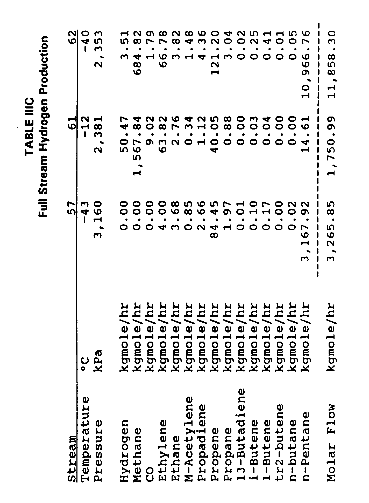
- Auto
refrigerated recovery unit 35, requiring no external refrigeration for condensation and demethanization of ethylene plus hydrocarbons in itsbottom stream 39, consequently also requires relatively little capital investment due to its significantly reduced size. In illustration, the flow rate of feed, on a molar basis, to auto refrigeratedrecovery unit 35 is 48% of the flow rate todemethanizing absorber column 29 in Example 2 and 31% in Example 3. However, a refrigerant no lower than -55°C may be utilized within the auto refrigeratedrecovery unit 35 if doing so will reduce the overall circulation rate of solvent required for absorbing ethylene plus hydrocarbons through thedemethanizing absorber unit 29. - For cracked gases, auto refrigeration is achieved through the use of turbo expanders which in turn provide chilling for demethanization and recovery of 1-25% of unrecovered ethylene through
demethanizing absorber 29. When FCC refinery off-gases are fed todemethanizing absorber column 29, the turbo expanders in auto refrigeratedrecovery unit 35 are replaced by pressure let-down valves to achieve the Joule-Thompson effect while limiting the chilling to a temperature no lower than - 110°C. This limitation ensures the safety aspects of the process, particularly by preventing the condensation of nitrogen oxides to form NOx within the system. - Most refinery off-gases contain nitrogen which is generally not present in a cracked gas stream. When nitrogen is present in the feed to the
demethanizing absorber column 29, the hydrogen purity ofstream 40 is limited by the nitrogen content of the feed since the process of this invention does not separate nitrogen from hydrogen. - Since most of the refinery off-gases are used as fuel within a refinery, these gases generally are at lower pressures consistent with the pressure within the fuel gas system. Depending upon the desired recovery of hydrogen in addition to the recovery of olefins and the required pressure of the hydrogen, it may not be necessary to compress the FCC gases. Accordingly, a simple deethanizer or a depropanizer without a heat-pumped overhead system may be utilized. If these gases do not contain acetylene, the overhead gases may directly flow into the
demethanizing absorber column 29.
Claims (24)
- A process for recovering ethylene from a hydrocarbon gas stream 27 which is comprised of hydrogen, methane, ethylene and ethane, and is essentially devoid of C4+ hydrocarbons, acetylenes, diolefins and water, fed to a demethanizing absorber column 29 employing a hydrocarbon solvent to produce an overhead gas stream 31 containing methane and minor quantities of ethylene and a bottom solvent stream 33 rich in ethylene-and-heavier hydrocarbons, said overhead gas stream 31 being separated by an auto refrigerated recovery unit 35, wherein auto refrigeration is achieved through use of turbo expanders or pressure let-down valves followed by demethanization utilizing a demethanizer column, to produce a C2-plus stream 39, a recovered solvent stream 32 and a fuel gas stream 37, and said bottom rich solvent stream 33 being separated by a solvent regenerator column 53 to produce a demethanized ethylene-and-heavier overhead stream 55 and a lean solvent stream 57 for recycling to said demethanizing absorber column 29, said process requiring no external refrigeration to a temperature below -55°C, said process comprising:A. selecting said hydrocarbon solvent from the group consisting of:(1) paraffinic hydrocarbons having 4 to 10 carbon atoms,(2) naphthenic hydrocarbons having 4 to 10 carbon atoms,(3) aromatic hydrocarbons, selected from the group consisting of benzene, toluene, C8-C10 aromatic compounds having methyl, ethyl or propyl aliphatic groups specifically o-xylene, m-xylene, p-xylene, hemimellitene, pseudocumene, mesitylene, cumene, o-ethyltoluene, m-ethyltoluene, p-ethyltoluene, n-propylbenzene, isopropylbenzene, indane, durene, isodurene, prehnitene, crude xylenes, toluene transalkylation reaction effluents, extracted C9 naphtha reformates, C9 heart cuts of said reformates which are enriched in C9 alkylbenzenes, C7-C9 alkyl aromatics, and mixtures thereof, and(4) mixtures of said paraffinic hydrocarbons, said naphthenic hydrocarbons, and/or said aromatic hydrocarbons;B. intercooling and interreboiling said demethanizing absorber column 29 and adjusting the lean solvent circulation rate thereto to absorb 75% to 99% of said ethylene present in said hydrocarbon gas stream 27 into said rich solvent stream 33; andC. utilizing said demethanizer column within said auto refrigerated recovery unit 35 for:(1) recovering 1% to 25% of said ethylene present in said hydrocarbon gas stream 27 as a component of said C2-plus stream 39, and(2) producing said fuel gas stream 37 to contain as low as 0.1% of said ethylene present in said hydrocarbon gas stream 27.
- The process of claim 1, wherein excess solvent present in said overhead gas stream 31 is recovered in said auto refrigerated recovery unit 35.
- The process of claim 1 or 2, wherein said demethanized ethylene-and-heavier overhead gas stream 55 is combined with said C2-plus stream 39 to produce a combined ethylene-rich stream 42 that is fed to a deethanizer column 41 to produce a bottom stream 45 of propylene and heavier hydrocarbons and an overhead stream 43 of ethylene and ethane.
- The process of claim 3, wherein said overhead stream 43 of ethylene and ethane is fed to a C2 splitter column 47 to produce a bottom stream 51 of ethane and an overhead stream 49 of ethylene that amounts to at least 99% of said ethylene in said hydrocarbon gas stream 27.
- The process of claim 1 or 2, wherein said hydrocarbon gas stream 27 and said overhead gas stream 31 from said demethanizing absorber column 29 additionally contain hydrogen.
- The process of claim 5, wherein, when recovery of up to 50% of said hydrogen in said hydrocarbon gas stream 27 is desirable, said overhead gas stream 31 is selectively split into a hydrogen portion stream 34 and a fuel portion stream 36, said hydrogen portion stream 34 being fed to a methane absorber column 30 and said fuel portion stream 36 being fed to said auto refrigerated recovery unit 35.
- The process of claim 6, wherein said methane absorber column 30 produces an overhead hydrogen stream 40, containing said up to 50% of said hydrogen in said hydrocarbon gas stream 27, and a bottom rich solvent stream 38 which is fed to said demethanizing absorber column 29.
- The process of claim 7, wherein said bottom lean solvent stream 57 from said solvent regenerator column 53 is selectively split into a methane portion stream 59 and an ethylene portion stream 58, said ethylene portion stream 58 being fed to said demethanizing absorber column 29 and said methane portion stream 59 being fed to said methane absorber column 30.
- The process of claim 5, wherein, when recovery of 20% to 100% of said hydrogen in said hydrocarbon gas stream 27 is desirable, said overhead gas stream 31 from said demethanizing absorber column 29 is fed to a methane absorber column 30 which produces a hydrogen stream 40, containing said 20% to 100% of said hydrogen in said hydrocarbon gas stream 27, and a bottom rich solvent stream 38.
- The process of claim 9, wherein said bottom rich solvent stream 38 from said methane absorber column 30 is selectively split into an absorber portion stream 48 and a stripper portion stream 46, said absorber portion stream 48 being fed to said demethanizing absorber column 29 and said stripper portion stream 46 being fed to a methane stripper column 60.
- The process of claim 10, wherein said methane stripper column 60 produces a bottom solvent stream 62 which is recycled to said methane absorber column 30 and an overhead stream 61 which is fed to said auto refrigerated recovery unit 35.
- The process of claims 6, 8, and 10, wherein said selective splits form a means for shifting an entire plant to recovering said desirable percentage of hydrogen, while changing only the composition of said fuel gas stream 37 and without affecting the production and composition of said combined ethylene-rich stream 42.
- The process of claim 1 or 2, wherein a cooled, sweetened, and compressed hydrocarbon gas stream 11, containing hydrogen, methane, ethylene, ethane, acetylene, and the C3 and heavier hydrocarbons characteristic of an ethylene plant cracked gas stream and/or a refinery off-gas stream, is treated to form said hydrocarbon gas stream 27.
- The process of claim 13, wherein said cooled, sweetened, and compressed hydrocarbon gas stream 11 is treated by a heat-pumped depropanizer column 13 which is coupled with a front-end selective catalytic acetylene hydrogenation reactor system 18 to produce a C3-and-lighter overhead stream that is fed to said demethanizing absorber column 29 as said hydrocarbon gas stream 27.
- The process of claim 13, wherein said cooled, sweetened, and compressed hydrocarbon gas stream 11 is treated by a heat-pumped deethanizer column 13 which is coupled with a front-end selective catalytic acetylene hydrogenation reactor system 18 to produce a C2-and-lighter overhead stream that is fed to said demethanizing absorber column 29 as said hydrocarbon gas stream 27.
- The process of claim 15, wherein said C2-plus stream 39 from said auto refrigerated recovery unit 35 is combined with said overhead stream 55 from said solvent regenerator column 53 to produce a combined ethylene-rich stream 42 that is fed to a C2 splitter column 47 to produce a bottom stream 51 of ethane and an overhead stream 49 of ethylene that amounts to at least 99% of said ethylene in said hydrocarbon gas stream 27.
- The process of claim 13, wherein:A. said cooled, sweetened, and compressed hydrocarbon gas stream 27 is a cracked gas stream; andB. auto refrigeration is achieved through use of turbo expanders which in turn provide chilling for demethanization and recovery of said up to 25% of said ethylene present in said hydrocarbon gas stream 27 as said C2-plus stream 39.
- The process of claim 13, wherein:A. said cooled, sweetened, and compressed hydrocarbon gas stream 11 is an FCC refinery off-gas stream that additionally contains nitrogen; andB. auto refrigeration is provided through use of pressure let-down valves which in turn provide chilling to achieve the Joule-Thompson effect while limiting said chilling to a temperature no lower than -110°C, whereby nitrogen oxides are prevented from condensing.
- The process of claim 1 or 2, wherein a cooled, sweetened, and compressed hydrocarbon gas stream 11, containing hydrogen, methane, ethylene, ethane, and the C3 and heavier hydrocarbons characteristic of a refinery off-gas stream containing nitrogen but essentially no C2 acetylene, is treated by a deethanizer column without catalytic hydrogenation to produce a C2-and-lighter overhead stream that is fed to said demethanizing absorber column 29 as said hydrocarbon gas stream 27.
- The process of claim 1 or 2, wherein a cooled, sweetened, and compressed hydrocarbon gas stream 11, containing hydrogen, methane, ethylene, ethane, and the C3 and heavier hydrocarbons characteristic of a refinery off-gas containing nitrogen but essentially no C2 acetylene, is treated by a depropanizer column without catalytic hydrogenation to produce a C3-and-lighter overhead stream that is fed to said demethanizing absorber column 29 as said hydrocarbon gas stream 27.
- The process of claims 19 or 20, wherein said deethanizer column operates as a heat-pumped deethanizer column and said depropanizer column operates as a heat-pumped depropanizer column.
- The process of claim 1 or 2, wherein said external refrigeration is not required in said auto refrigerated recovery unit 35.
- The process of claim 7, wherein said solvent circulates as a single solvent loop, the circulation rate of which is determined by the C2+ content of said hydrocarbon gas stream 27.
- The process of claim 11, wherein said solvent circulates as two solvent loops that comprise a minor solvent loop circulating through said methane absorber column 30, said demethanizing absorber column 29, and said solvent regenerator column 53 and a major solvent loop circulating through said methane stripper column 60 and said methane absorber column 30, the circulation rate of said minor solvent circulation loop being determined by the C2-and-heavier content of said hydrocarbon gas stream 27 and the circulation rate of said major solvent circulation loop being determined by subtracting the flow rate of said bottom lean solvent stream 57 produced by said solvent regenerator column 53 from the total solvent circulation rate required to absorb the contained methane in said overhead gas stream 31 produced by said demethanizing absorber column 29.
Applications Claiming Priority (5)
| Application Number | Priority Date | Filing Date | Title |
|---|---|---|---|
| US836911 | 1992-02-19 | ||
| US07/836,911 US5220097A (en) | 1992-02-19 | 1992-02-19 | Front-end hydrogenation and absorption process for ethylene recovery |
| US937156 | 1992-08-31 | ||
| US07/937,156 US5326929A (en) | 1992-02-19 | 1992-08-31 | Absorption process for hydrogen and ethylene recovery |
| PCT/US1992/008390 WO1993017081A1 (en) | 1992-02-19 | 1992-10-02 | Absorption process for ethylene and hydrogen recovery |
Publications (2)
| Publication Number | Publication Date |
|---|---|
| EP0626989A1 EP0626989A1 (en) | 1994-12-07 |
| EP0626989B1 true EP0626989B1 (en) | 1997-04-23 |
Family
ID=27125897
Family Applications (1)
| Application Number | Title | Priority Date | Filing Date |
|---|---|---|---|
| EP92922526A Expired - Lifetime EP0626989B1 (en) | 1992-02-19 | 1992-10-02 | Absorption process for ethylene and hydrogen recovery |
Country Status (13)
| Country | Link |
|---|---|
| US (1) | US5326929A (en) |
| EP (1) | EP0626989B1 (en) |
| JP (1) | JP3242109B2 (en) |
| KR (1) | KR100230672B1 (en) |
| CN (1) | CN1034165C (en) |
| AU (1) | AU671086B2 (en) |
| BR (1) | BR9207086A (en) |
| CA (1) | CA2130567A1 (en) |
| DE (1) | DE69219365T2 (en) |
| MY (1) | MY109033A (en) |
| RU (1) | RU2105036C1 (en) |
| TW (1) | TW279855B (en) |
| WO (1) | WO1993017081A1 (en) |
Families Citing this family (45)
| Publication number | Priority date | Publication date | Assignee | Title |
|---|---|---|---|---|
| US5462583A (en) * | 1994-03-04 | 1995-10-31 | Advanced Extraction Technologies, Inc. | Absorption process without external solvent |
| US5546764A (en) * | 1995-03-03 | 1996-08-20 | Advanced Extraction Technologies, Inc. | Absorption process for recovering ethylene and hydrogen from refinery and petrochemical plant off-gases |
| US5521264A (en) * | 1995-03-03 | 1996-05-28 | Advanced Extraction Technologies, Inc. | Gas phase olefin polymerization process with recovery of monomers from reactor vent gas by absorption |
| US5681908A (en) * | 1995-03-03 | 1997-10-28 | Advanced Extraction Technologies, Inc. | Absorption process for rejection of reactor byproducts and recovery of monomers from waste gas streams in olefin polymerization processes |
| RU2201748C2 (en) | 1996-05-14 | 2003-04-10 | Уорвик Мёрроу ДЖЕЙМСОН | Ethene-containing solutions and their usage either in therapeutical methods or for prophylaxis |
| US6395952B1 (en) * | 1996-08-16 | 2002-05-28 | Stone & Webster Process Technology, Inc. | Chemical absorption process for recovering olefins from cracked gases |
| US5763715A (en) * | 1996-10-08 | 1998-06-09 | Stone & Webster Engineering Corp. | Butadiene removal system for ethylene plants with front end hydrogenation systems |
| US5859304A (en) * | 1996-12-13 | 1999-01-12 | Stone & Webster Engineering Corp. | Chemical absorption process for recovering olefins from cracked gases |
| US6158241A (en) * | 1998-01-01 | 2000-12-12 | Erickson; Donald C. | LPG recovery from reformer treat gas |
| FR2797641B1 (en) * | 1999-08-17 | 2001-09-21 | Inst Francais Du Petrole | PROCESS AND DEVICE FOR SEPARATING ETHANE AND ETHYLENE BY SOLVENT ABSORPTION AND HYDROGENATION OF THE SOLVENT PHASE AND REGENERATION OF THE SOLVENT |
| FR2797640B1 (en) * | 1999-08-17 | 2001-09-21 | Inst Francais Du Petrole | METHOD AND DEVICE FOR SEPARATING ETHANE AND ETHYLENE FROM A STEAM CRACKING EFFLUENT BY SOLVENT ABSORPTION AND HYDROGENATION OF THE SOLVENT PHASE |
| US6297414B1 (en) | 1999-10-08 | 2001-10-02 | Stone & Webster Process Technology, Inc. | Deep selective hydrogenation process |
| CN1114582C (en) * | 1999-10-26 | 2003-07-16 | 中国寰球工程公司 | Solvent suction process for separation of hydrocarbon mixture |
| US6593506B1 (en) | 2000-10-12 | 2003-07-15 | Exxonmobil Chemical Patents Inc. | Olefin recovery in a polyolefin production process |
| US6495609B1 (en) | 2000-11-03 | 2002-12-17 | Exxonmobil Chemical Patents Inc. | Carbon dioxide recovery in an ethylene to ethylene oxide production process |
| JP4568448B2 (en) * | 2001-03-30 | 2010-10-27 | 出光興産株式会社 | Hydrogen production plant and hydrogen production method |
| EP1507838B1 (en) * | 2001-11-16 | 2011-09-14 | Chevron Phillips Chemical Company Lp | A process to produce a dilute ethylene stream and a dilute propylene stream |
| US6783659B2 (en) * | 2001-11-16 | 2004-08-31 | Chevron Phillips Chemical Company, L.P. | Process to produce a dilute ethylene stream and a dilute propylene stream |
| EP1378558A1 (en) * | 2002-07-05 | 2004-01-07 | DSM Hydrocarbons BV | Process for the recovery of an ethylene and propylene containing stream from a cracked gas resulting from hydrocarbon cracking |
| US7273542B2 (en) | 2003-04-04 | 2007-09-25 | Exxonmobil Chemical Patents Inc. | Process and apparatus for recovering olefins |
| US7259288B2 (en) * | 2004-02-26 | 2007-08-21 | Saudi Arabian Oil Company | Enhanced hydrogen recovery for hydroprocessing units |
| US7947860B2 (en) * | 2006-09-28 | 2011-05-24 | Uop Llc | Dividing wall separation in light olefin hydrocarbon processing |
| US20090155889A1 (en) * | 2007-12-13 | 2009-06-18 | Alstom Technology Ltd | System and method for regeneration of an absorbent solution |
| US8445740B2 (en) * | 2008-10-29 | 2013-05-21 | Lummus Technology Inc. | Absorber demethanizer for FCC process |
| US8399728B2 (en) * | 2008-10-29 | 2013-03-19 | Lummus Technology Inc. | Absorber demethanizer for methanol to olefins process |
| DE102010014155B4 (en) | 2010-04-08 | 2019-02-28 | Linde Aktiengesellschaft | Process for the treatment of FCC off-gas |
| CN102476976A (en) * | 2010-11-30 | 2012-05-30 | 中国石油化工集团公司 | Method for absorbing, separating and recovering light hydrocarbon |
| CN102304010B (en) * | 2011-07-11 | 2014-03-05 | 中国天辰工程有限公司 | Method for separating low carbon olefin mixed gas by rectifying and absorbing |
| CN102516006B (en) * | 2011-11-11 | 2014-07-02 | 天津大学 | Method and device for recovering ethylene in vinyl acetate production process |
| KR102011543B1 (en) * | 2012-06-27 | 2019-08-16 | 바져 라이센싱 엘엘씨 | Process for producing cumene |
| RU2501779C1 (en) * | 2012-11-16 | 2013-12-20 | Общество с ограниченной ответственностью "ВНИИОС-наука" (ООО "ВНИИОС-наука") | Method of separating ethylene of polymerisation purity from catalytic cracking gases |
| KR101483939B1 (en) * | 2014-01-21 | 2015-01-20 | 유인자 | Excavation Propulsion Apparatus of Underground Concrete Structure on Segement Construction Base |
| CN103880577B (en) * | 2014-03-20 | 2016-03-30 | 中国石油集团东北炼化工程有限公司吉林设计院 | For the reaction product separation system of preparing propylene from methanol and methanol-to-olefins |
| CN105439794B (en) * | 2014-07-25 | 2017-06-30 | 中国石油化工股份有限公司 | A kind of method that acetonitrile absorption and separation plant catalytic dry gas reclaim ethane and ethene |
| CN106608786B (en) * | 2015-10-22 | 2019-06-11 | 中国石油化工股份有限公司 | The method of alcohol ether dimethylbenzene coproduction ethylbenzene |
| KR102071591B1 (en) * | 2016-05-10 | 2020-01-30 | 주식회사 엘지화학 | Method for preparing of ethylene improved an energy efficiency |
| RU2640781C1 (en) * | 2016-08-08 | 2018-01-11 | федеральное государственное бюджетное образовательное учреждение высшего образования "Самарский государственный технический университет" | Method for purifying exhaust gases of isopropyl benzene oxidization |
| KR101867691B1 (en) * | 2016-09-09 | 2018-06-18 | 주식회사 효성 | Method for preparing ethylene in propylene manufacturing process using propane dehydrogenation process |
| US10052581B1 (en) * | 2017-09-20 | 2018-08-21 | Uop Llc | Process for recovery of cracker feed from dry gas |
| CN109678635B (en) * | 2017-10-19 | 2022-03-15 | 中国石油化工股份有限公司 | Saturated hydrocarbon cracking gas separation system and utilization method of ethane/propane-rich saturated hydrocarbon |
| KR102416636B1 (en) * | 2018-09-04 | 2022-07-01 | 주식회사 엘지화학 | Method for preparing ethylene |
| KR102423688B1 (en) * | 2018-09-04 | 2022-07-21 | 주식회사 엘지화학 | Method for preparing ethylene and apparatus for preparing ethylene |
| WO2020050487A1 (en) * | 2018-09-04 | 2020-03-12 | 주식회사 엘지화학 | Ethylene manufacturing method and ethylene manufacturing device |
| US20200115301A1 (en) * | 2018-10-15 | 2020-04-16 | Uop Llc | Process for recovery of ethylene from dry gas |
| CN114471375B (en) * | 2020-10-23 | 2023-02-24 | 中国石油化工股份有限公司 | Device and method for fully hydrogenating mixed C4 material flow |
Family Cites Families (7)
| Publication number | Priority date | Publication date | Assignee | Title |
|---|---|---|---|---|
| US2938934A (en) * | 1958-06-04 | 1960-05-31 | Dow Chemical Co | Process for recovery of ethylene |
| US4740222A (en) * | 1982-05-03 | 1988-04-26 | Advanced Extraction Technologies, Inc. | Recovery and purification of hydrogen from refinery and petrochemical off-gas streams |
| US4832718A (en) * | 1982-05-03 | 1989-05-23 | Advanced Extraction Technologies, Inc. | Processing nitrogen-rich, hydrogen-rich, and olefin-rich gases with physical solvents |
| US4743282A (en) * | 1982-05-03 | 1988-05-10 | Advanced Extraction Technologies, Inc. | Selective processing of gases containing olefins by the mehra process |
| US4654063A (en) * | 1984-12-21 | 1987-03-31 | Air Products And Chemicals, Inc. | Process for recovering hydrogen from a multi-component gas stream |
| US5019143A (en) * | 1987-09-23 | 1991-05-28 | Mehrta Yuv R | Low pressure noncryogenic processing for ethylene recovery |
| US5220097A (en) * | 1992-02-19 | 1993-06-15 | Advanced Extraction Technologies, Inc. | Front-end hydrogenation and absorption process for ethylene recovery |
-
1992
- 1992-08-31 US US07/937,156 patent/US5326929A/en not_active Expired - Lifetime
- 1992-10-02 BR BR9207086A patent/BR9207086A/en not_active IP Right Cessation
- 1992-10-02 EP EP92922526A patent/EP0626989B1/en not_active Expired - Lifetime
- 1992-10-02 KR KR1019940702907A patent/KR100230672B1/en not_active IP Right Cessation
- 1992-10-02 AU AU27957/92A patent/AU671086B2/en not_active Ceased
- 1992-10-02 CA CA002130567A patent/CA2130567A1/en not_active Abandoned
- 1992-10-02 RU RU94039537A patent/RU2105036C1/en not_active IP Right Cessation
- 1992-10-02 WO PCT/US1992/008390 patent/WO1993017081A1/en active IP Right Grant
- 1992-10-02 JP JP51479593A patent/JP3242109B2/en not_active Expired - Fee Related
- 1992-10-02 DE DE69219365T patent/DE69219365T2/en not_active Expired - Fee Related
- 1992-10-09 TW TW081108046A patent/TW279855B/zh active
- 1992-10-13 MY MYPI92001836A patent/MY109033A/en unknown
- 1992-11-10 CN CN92112449A patent/CN1034165C/en not_active Expired - Fee Related
Also Published As
| Publication number | Publication date |
|---|---|
| TW279855B (en) | 1996-07-01 |
| MY109033A (en) | 1996-11-30 |
| RU2105036C1 (en) | 1998-02-20 |
| WO1993017081A1 (en) | 1993-09-02 |
| DE69219365T2 (en) | 1997-08-07 |
| US5326929A (en) | 1994-07-05 |
| AU671086B2 (en) | 1996-08-15 |
| CN1034165C (en) | 1997-03-05 |
| CA2130567A1 (en) | 1993-09-02 |
| RU94039537A (en) | 1996-07-10 |
| AU2795792A (en) | 1993-09-13 |
| JP3242109B2 (en) | 2001-12-25 |
| CN1075707A (en) | 1993-09-01 |
| KR950700380A (en) | 1995-01-16 |
| JPH07507078A (en) | 1995-08-03 |
| KR100230672B1 (en) | 1999-11-15 |
| BR9207086A (en) | 1995-12-12 |
| DE69219365D1 (en) | 1997-05-28 |
| EP0626989A1 (en) | 1994-12-07 |
Similar Documents
| Publication | Publication Date | Title |
|---|---|---|
| EP0626989B1 (en) | Absorption process for ethylene and hydrogen recovery | |
| US5220097A (en) | Front-end hydrogenation and absorption process for ethylene recovery | |
| EP0381720B1 (en) | Low pressure noncryogenic processing for ethylene recovery | |
| US4743282A (en) | Selective processing of gases containing olefins by the mehra process | |
| US5859304A (en) | Chemical absorption process for recovering olefins from cracked gases | |
| US5090977A (en) | Sequence for separating propylene from cracked gases | |
| EP0393029B1 (en) | Processing nitrogen-rich, hydrogen-rich, and olefin-rich gases with physical solvents | |
| US6578378B2 (en) | Process and installation for recovery and purification of ethylene produced by pyrolysis of hydrocarbons, and gases obtained by this process | |
| US5372009A (en) | Cryogenic distillation | |
| WO2000031214A2 (en) | Recovery of propylene and ethylene from offgases |
Legal Events
| Date | Code | Title | Description |
|---|---|---|---|
| PUAI | Public reference made under article 153(3) epc to a published international application that has entered the european phase |
Free format text: ORIGINAL CODE: 0009012 |
|
| 17P | Request for examination filed |
Effective date: 19940831 |
|
| AK | Designated contracting states |
Kind code of ref document: A1 Designated state(s): DE FR GB IT NL |
|
| 17Q | First examination report despatched |
Effective date: 19950609 |
|
| GRAG | Despatch of communication of intention to grant |
Free format text: ORIGINAL CODE: EPIDOS AGRA |
|
| GRAH | Despatch of communication of intention to grant a patent |
Free format text: ORIGINAL CODE: EPIDOS IGRA |
|
| RBV | Designated contracting states (corrected) |
Designated state(s): DE FR GB IT NL |
|
| GRAH | Despatch of communication of intention to grant a patent |
Free format text: ORIGINAL CODE: EPIDOS IGRA |
|
| GRAH | Despatch of communication of intention to grant a patent |
Free format text: ORIGINAL CODE: EPIDOS IGRA |
|
| GRAH | Despatch of communication of intention to grant a patent |
Free format text: ORIGINAL CODE: EPIDOS IGRA |
|
| GRAA | (expected) grant |
Free format text: ORIGINAL CODE: 0009210 |
|
| AK | Designated contracting states |
Kind code of ref document: B1 Designated state(s): DE FR GB IT NL |
|
| ITF | It: translation for a ep patent filed |
Owner name: JACOBACCI & PERANI S.P.A. |
|
| REF | Corresponds to: |
Ref document number: 69219365 Country of ref document: DE Date of ref document: 19970528 |
|
| ET | Fr: translation filed | ||
| PLBE | No opposition filed within time limit |
Free format text: ORIGINAL CODE: 0009261 |
|
| STAA | Information on the status of an ep patent application or granted ep patent |
Free format text: STATUS: NO OPPOSITION FILED WITHIN TIME LIMIT |
|
| 26N | No opposition filed | ||
| REG | Reference to a national code |
Ref country code: GB Ref legal event code: IF02 |
|
| PGFP | Annual fee paid to national office [announced via postgrant information from national office to epo] |
Ref country code: GB Payment date: 20021002 Year of fee payment: 11 |
|
| PGFP | Annual fee paid to national office [announced via postgrant information from national office to epo] |
Ref country code: FR Payment date: 20021008 Year of fee payment: 11 |
|
| PGFP | Annual fee paid to national office [announced via postgrant information from national office to epo] |
Ref country code: DE Payment date: 20021011 Year of fee payment: 11 |
|
| PGFP | Annual fee paid to national office [announced via postgrant information from national office to epo] |
Ref country code: NL Payment date: 20021031 Year of fee payment: 11 |
|
| PG25 | Lapsed in a contracting state [announced via postgrant information from national office to epo] |
Ref country code: GB Free format text: LAPSE BECAUSE OF NON-PAYMENT OF DUE FEES Effective date: 20031002 |
|
| PG25 | Lapsed in a contracting state [announced via postgrant information from national office to epo] |
Ref country code: NL Free format text: LAPSE BECAUSE OF NON-PAYMENT OF DUE FEES Effective date: 20040501 Ref country code: DE Free format text: LAPSE BECAUSE OF NON-PAYMENT OF DUE FEES Effective date: 20040501 |
|
| GBPC | Gb: european patent ceased through non-payment of renewal fee |
Effective date: 20031002 |
|
| PG25 | Lapsed in a contracting state [announced via postgrant information from national office to epo] |
Ref country code: FR Free format text: LAPSE BECAUSE OF NON-PAYMENT OF DUE FEES Effective date: 20040630 |
|
| NLV4 | Nl: lapsed or anulled due to non-payment of the annual fee |
Effective date: 20040501 |
|
| REG | Reference to a national code |
Ref country code: FR Ref legal event code: ST |
|
| PG25 | Lapsed in a contracting state [announced via postgrant information from national office to epo] |
Ref country code: IT Free format text: LAPSE BECAUSE OF NON-PAYMENT OF DUE FEES;WARNING: LAPSES OF ITALIAN PATENTS WITH EFFECTIVE DATE BEFORE 2007 MAY HAVE OCCURRED AT ANY TIME BEFORE 2007. THE CORRECT EFFECTIVE DATE MAY BE DIFFERENT FROM THE ONE RECORDED. Effective date: 20051002 |