EP0629085B1 - Digital high definition television receiver with features that facilitate trick-play modes on a digital vcr - Google Patents
Digital high definition television receiver with features that facilitate trick-play modes on a digital vcr Download PDFInfo
- Publication number
- EP0629085B1 EP0629085B1 EP94108312A EP94108312A EP0629085B1 EP 0629085 B1 EP0629085 B1 EP 0629085B1 EP 94108312 A EP94108312 A EP 94108312A EP 94108312 A EP94108312 A EP 94108312A EP 0629085 B1 EP0629085 B1 EP 0629085B1
- Authority
- EP
- European Patent Office
- Prior art keywords
- signal
- encoded
- resolution
- data
- video signal
- Prior art date
- Legal status (The legal status is an assumption and is not a legal conclusion. Google has not performed a legal analysis and makes no representation as to the accuracy of the status listed.)
- Expired - Lifetime
Links
Images


Classifications
-
- H—ELECTRICITY
- H04—ELECTRIC COMMUNICATION TECHNIQUE
- H04N—PICTORIAL COMMUNICATION, e.g. TELEVISION
- H04N5/00—Details of television systems
- H04N5/76—Television signal recording
-
- G—PHYSICS
- G06—COMPUTING; CALCULATING OR COUNTING
- G06T—IMAGE DATA PROCESSING OR GENERATION, IN GENERAL
- G06T3/00—Geometric image transformation in the plane of the image
- G06T3/40—Scaling the whole image or part thereof
- G06T3/4084—Transform-based scaling, e.g. FFT domain scaling
-
- G—PHYSICS
- G06—COMPUTING; CALCULATING OR COUNTING
- G06T—IMAGE DATA PROCESSING OR GENERATION, IN GENERAL
- G06T3/00—Geometric image transformation in the plane of the image
- G06T3/40—Scaling the whole image or part thereof
-
- H—ELECTRICITY
- H04—ELECTRIC COMMUNICATION TECHNIQUE
- H04N—PICTORIAL COMMUNICATION, e.g. TELEVISION
- H04N19/00—Methods or arrangements for coding, decoding, compressing or decompressing digital video signals
- H04N19/40—Methods or arrangements for coding, decoding, compressing or decompressing digital video signals using video transcoding, i.e. partial or full decoding of a coded input stream followed by re-encoding of the decoded output stream
-
- H—ELECTRICITY
- H04—ELECTRIC COMMUNICATION TECHNIQUE
- H04N—PICTORIAL COMMUNICATION, e.g. TELEVISION
- H04N21/00—Selective content distribution, e.g. interactive television or video on demand [VOD]
- H04N21/20—Servers specifically adapted for the distribution of content, e.g. VOD servers; Operations thereof
- H04N21/23—Processing of content or additional data; Elementary server operations; Server middleware
- H04N21/236—Assembling of a multiplex stream, e.g. transport stream, by combining a video stream with other content or additional data, e.g. inserting a URL [Uniform Resource Locator] into a video stream, multiplexing software data into a video stream; Remultiplexing of multiplex streams; Insertion of stuffing bits into the multiplex stream, e.g. to obtain a constant bit-rate; Assembling of a packetised elementary stream
-
- H—ELECTRICITY
- H04—ELECTRIC COMMUNICATION TECHNIQUE
- H04N—PICTORIAL COMMUNICATION, e.g. TELEVISION
- H04N21/00—Selective content distribution, e.g. interactive television or video on demand [VOD]
- H04N21/40—Client devices specifically adapted for the reception of or interaction with content, e.g. set-top-box [STB]; Operations thereof
- H04N21/41—Structure of client; Structure of client peripherals
- H04N21/414—Specialised client platforms, e.g. receiver in car or embedded in a mobile appliance
- H04N21/4147—PVR [Personal Video Recorder]
-
- H—ELECTRICITY
- H04—ELECTRIC COMMUNICATION TECHNIQUE
- H04N—PICTORIAL COMMUNICATION, e.g. TELEVISION
- H04N21/00—Selective content distribution, e.g. interactive television or video on demand [VOD]
- H04N21/40—Client devices specifically adapted for the reception of or interaction with content, e.g. set-top-box [STB]; Operations thereof
- H04N21/43—Processing of content or additional data, e.g. demultiplexing additional data from a digital video stream; Elementary client operations, e.g. monitoring of home network or synchronising decoder's clock; Client middleware
- H04N21/434—Disassembling of a multiplex stream, e.g. demultiplexing audio and video streams, extraction of additional data from a video stream; Remultiplexing of multiplex streams; Extraction or processing of SI; Disassembling of packetised elementary stream
-
- H—ELECTRICITY
- H04—ELECTRIC COMMUNICATION TECHNIQUE
- H04N—PICTORIAL COMMUNICATION, e.g. TELEVISION
- H04N5/00—Details of television systems
- H04N5/76—Television signal recording
- H04N5/91—Television signal processing therefor
- H04N5/92—Transformation of the television signal for recording, e.g. modulation, frequency changing; Inverse transformation for playback
- H04N5/926—Transformation of the television signal for recording, e.g. modulation, frequency changing; Inverse transformation for playback by pulse code modulation
- H04N5/9261—Transformation of the television signal for recording, e.g. modulation, frequency changing; Inverse transformation for playback by pulse code modulation involving data reduction
- H04N5/9264—Transformation of the television signal for recording, e.g. modulation, frequency changing; Inverse transformation for playback by pulse code modulation involving data reduction using transform coding
-
- H—ELECTRICITY
- H04—ELECTRIC COMMUNICATION TECHNIQUE
- H04N—PICTORIAL COMMUNICATION, e.g. TELEVISION
- H04N9/00—Details of colour television systems
- H04N9/79—Processing of colour television signals in connection with recording
- H04N9/80—Transformation of the television signal for recording, e.g. modulation, frequency changing; Inverse transformation for playback
- H04N9/804—Transformation of the television signal for recording, e.g. modulation, frequency changing; Inverse transformation for playback involving pulse code modulation of the colour picture signal components
- H04N9/8042—Transformation of the television signal for recording, e.g. modulation, frequency changing; Inverse transformation for playback involving pulse code modulation of the colour picture signal components involving data reduction
-
- H—ELECTRICITY
- H04—ELECTRIC COMMUNICATION TECHNIQUE
- H04N—PICTORIAL COMMUNICATION, e.g. TELEVISION
- H04N5/00—Details of television systems
- H04N5/76—Television signal recording
- H04N5/78—Television signal recording using magnetic recording
- H04N5/782—Television signal recording using magnetic recording on tape
- H04N5/7824—Television signal recording using magnetic recording on tape with rotating magnetic heads
- H04N5/7826—Television signal recording using magnetic recording on tape with rotating magnetic heads involving helical scanning of the magnetic tape
- H04N5/78263—Television signal recording using magnetic recording on tape with rotating magnetic heads involving helical scanning of the magnetic tape for recording on tracks inclined relative to the direction of movement of the tape
- H04N5/78266—Television signal recording using magnetic recording on tape with rotating magnetic heads involving helical scanning of the magnetic tape for recording on tracks inclined relative to the direction of movement of the tape using more than one track for the recording of one television field or frame, i.e. segmented recording
-
- H—ELECTRICITY
- H04—ELECTRIC COMMUNICATION TECHNIQUE
- H04N—PICTORIAL COMMUNICATION, e.g. TELEVISION
- H04N5/00—Details of television systems
- H04N5/76—Television signal recording
- H04N5/78—Television signal recording using magnetic recording
- H04N5/782—Television signal recording using magnetic recording on tape
- H04N5/783—Adaptations for reproducing at a rate different from the recording rate
-
- H—ELECTRICITY
- H04—ELECTRIC COMMUNICATION TECHNIQUE
- H04N—PICTORIAL COMMUNICATION, e.g. TELEVISION
- H04N9/00—Details of colour television systems
- H04N9/79—Processing of colour television signals in connection with recording
- H04N9/80—Transformation of the television signal for recording, e.g. modulation, frequency changing; Inverse transformation for playback
- H04N9/82—Transformation of the television signal for recording, e.g. modulation, frequency changing; Inverse transformation for playback the individual colour picture signal components being recorded simultaneously only
- H04N9/8205—Transformation of the television signal for recording, e.g. modulation, frequency changing; Inverse transformation for playback the individual colour picture signal components being recorded simultaneously only involving the multiplexing of an additional signal and the colour video signal
- H04N9/8227—Transformation of the television signal for recording, e.g. modulation, frequency changing; Inverse transformation for playback the individual colour picture signal components being recorded simultaneously only involving the multiplexing of an additional signal and the colour video signal the additional signal being at least another television signal
Definitions
- the present invention concerns high definition television receivers and in particular a receiver which processes a received high definition video signal to produce data representing both a high resolution image and a low resolution image for recording by a VCR.
- Digital high definition television production schemes have been under development for several years. These schemes typically produce higher quality television images and sound than conventional television systems. To do this, these systems convey more information than is conveyed in a conventional television signal.
- One such compression method by which spatial redundancy is removed from a television signal, generates discrete cosine transform representations of blocks of the image.
- This representation resolves an image frame into coefficient values representing its various spatial frequency components. Portions of an image which are the same from pixel to pixel or which exhibit a repetitive pattern are resolved from many pixel values to a relatively small number of frequency coefficient values.
- the high spatial frequency coefficients may be quantized more coarsely than the low spatial frequency coefficients to further reduce the amount of data used to represent the image.
- Temporal redundancy in an image may be removed by encoding only the areas of a given frame which are different from corresponding areas of a previously encoded frame. This is generally known as predictive coding. Temporal redundancy can be further exploited to achieve even higher levels of data compression by performing motion compensation. Using this scheme, before a image block is encoded, the blocks surrounding it in a previously encoded frame are searched for the one block which most closely matches the block in the current frame. The current block is then subtracted from the matching block in the previous frame and only the difference values are encoded.
- An exemplary video image compression system which employs motion-compensated predictive encoding techniques is that proposed by the Motion Picture Experts Group (MPEG) and described in the document entitled “Coded Representation of Picture and Audio Information” ISO-IEC/JTC1/SC2/WG11 N0010 MPEG 90/41 dated July 25, 1990.
- MPEG Motion Picture Experts Group
- encoding techniques are also used in the MPEG system such as run-length coding, in which strings of identical values are encoded as a smaller number of values; and variable length coding, in which frequently occurring data values are assigned a digital code value having fewer bits than less frequently occurring data values.
- the decoding apparatus may include one or more frame memories which hold images that have already been decoded. The pixel values held by these memories are used to reconstruct the predictively encoded data in the current frame.
- HDTV signals having a data rate of between 600 and 1200 Megabits per second (Mbps) can be compressed to produce a signal having a data rate of less than 20 Mbps.
- Mbps Megabits per second
- consumers will want to be able to receive, display and record signals representing high resolution video images with little no loss of resolution.
- VCR Video Cassette Recorders
- a typical HDTV signal prior to encoding, has a bit-rate of 600 Mbps.
- Compression methods such as MPEG can reduce these HDTV signals to have a bit-rate of approximately 18 Mbps without noticeably degrading the image quality when the compressed signal is expanded.
- Video information is recorded on a VCR in data blocks referred to as slices, which represent fixed-size portions of an image.
- slices represent fixed-size portions of an image.
- some slices are encoded using intra-frame techniques while others are encoded using predictive techniques.
- the data blocks representing the slices are recorded as they occur in the video data stream.
- the amount of data in a slice may vary from slice-to-slice. This variation occurs because of the relative coding efficiencies of the slices in the original HDTV signal.
- Slices which represent still portions of a multi-frame image or which represent portions having relatively little variation may be encoded using a relatively small number of data values. Image portions containing a high level of detail and having no corresponding portions in previously encoded frames may require a significantly larger number of data values when they are encoded.
- each slice of each frame is read from the tape in sequence.
- the recorded data includes both intra-frame coded data and predictively coded data.
- the pixel values for the intra-frame encoded portions are stored in a memory and are available for use in reconstructing the predicted frames.
- VTR's video tape recorders
- Exemplary systems of this type are described in an article by C. Yamamitsu, et al. entitled “An Experimental Study for a Home-Use Digital VTR", IEEE Transactions on Consumer Electronics , Volume 35, No. 3, August 1989, PP. 450-457, and in a paper by J.
- EP-A-0 353 758 discloses a digital video recording apparatus, which receives uncoded video data, generates a compressed low-resolution version of selected frames of the received video data, compresses the received video data and records the generated low-resolution data with the compressed video data.
- EP-A-0 613 297 discloses a video tape recorder which receives an encoded and compressed high-resolution video signal, generates a compressed and encoded low-resolution version of the received signal and records the generated low-resolution signal with the high-resolution signal such that the low-resolution signal may be reproduced from the tape in trick-play modes such as fast forward and rewind.
- document US 4,845,564 discloses a television signal receiver comprising means for receiving a first encoded video signal; recording means for recording the first encoded video signal; first decoding means for decoding the first encoded video signal to produce a first decoded digital signal representing a first video image sequence; subsampling means, responsive to the first decoded digital signal, for generating a low-resolution video signal representing a reduced version of the entire first video mage sequence; output means for providing the first encoded video signal at the output terminal; means for receiving an encoded second video signal; means for decoding the encoded second video signal to produce a second decoded signal representing a second video image sequence; and means for multiplexing the second decoded signal and the low-resolution video signal to produce a composite signal representing the second video image sequence having the reduced resolution version of the first video image sequence as an inset.
- the present invention is embodied in a high-television receiver comprising means for receiving a first compressed and encoded high-definition video signal; first decoding means for decoding the first compressed and encoded high-definition video signal to produce a first decoded digital signal representing a first high-definition video image sequence; subsampling means, responsive to the first decoded digital signal, for generating a low-resolution video signal representing a reduced resolution version of the entire first high-definition video image sequence; means for compressing and encoding the low-resolution video signal to produce a compressed and encoded low-resolution video signal; output means for providing the first compressed an encoded high-definition video signal and the compressed and encoded low-resolution first video signal at an output terminal; means for receiving a second compressed and encoded high-definition video signal; means for decoding the compressed and encoded high-definition second video signal to produce a second decoded digital signal representing a second high-definition video image sequence; and means for mutiplex
- One data stream represents an HDTV video signal which has been encoded using both intra-frame and motion compensated encoding techniques.
- the second data stream represents a low resolution image which is sufficient for display in trick-play modes and which may be efficiently compressed to a relatively small number of data values using only intra-frame encoding techniques.
- the two data streams are provided by the television receiver either as a single multiplexed stream or as two independent streams.
- each of the data streams is separated into relatively small data segments which are time-division-multiplexed for recording on the tape.
- the segments of at least one of the data streams are identified by a header.
- the low resolution segments have fixed minimum and maximum lengths and recorded at predetermined locations on the tape. These locations are selected to be in the path of the tape head during selected trick-play modes.
- Two alternative trick-play display modes are disclosed.
- a rotating segment from each frame is displayed to produce a complete image composed of different parts of each frame.
- images from single frames are displayed but only for selected frames in the sequence of frames (e.g. every third frame).
- Data representing the full compressed image is also recorded on the tape so that, in normal play modes, a complete high definition image may be recovered and displayed.
- FIG. 1 is a block diagram of a television receiver in accordance with a first exemplary embodiment of the invention.
- a digital data stream representing a baseband HDTV video signal is received at terminal 110.
- This data stream may be provided, for example, by a television tuner (not shown) followed by a demodulator/decoder (not shown) which recovers a 32 state quadrature amplitude modulated (32-QAM) signal.
- 32-QAM 32 state quadrature amplitude modulated
- the HDTV decoder 112 is the main decoder for the television receiver. If the HDTV video signal is encoded according to the motion-picture experts group (MPEG) standard, then the HDTV decoder 112 may include circuitry (not shown) to expand run length encoded and variable length encoded data, circuitry (not shown) to reverse the adaptive quantization applied in the MPEG encoding process, an inverse discrete cosine transform (IDCT) decoder (not shown), and a frame memory (not shown) for reversing any motion compensated encoding which may have been performed in the MPEG encoder.
- MPEG motion-picture experts group
- the exemplary HDTV encoder 112 produces blocks of pixel values representing a high definition video image.
- these blocks may include 64 pixels arranged in an 8 x 8 matrix.
- the blocks of pixel values are applied to a block to raster converter 136.
- This circuit which may include a frame memory buffer (not shown), produces pixel values in raster scan order which are applied to post processing circuitry 138.
- the circuitry 138 uses well known techniques to process the raster scan pixel values provided by the circuitry 136 to generate analog red (R) green (G) and blue (B) signals and to regenerate horizontal and vertical synchronization signals (SYNC). These signals are used to drive a video display (not shown) to reproduce the high definition image sequence.
- the blocks of pixel values provided by the decoder 112 are also applied to circuitry 114 which low pass filters and subsamples or decimates the blocks of pixel values to produce pixel values representing a reduced resolution image.
- the blocks of pixel values are subsampled by a factor of 1/2 in each of the horizontal and vertical directions. Accordingly, each block of 64 pixels which is applied to the filter and decimate circuitry 114 produces a block of 16 pixels.
- the low-pass filter component of the block 114 acts as an antialiasing filter.
- a discrete cosine transform circuit 116 transforms the pixel values in each block into a block of coefficient values each representing a respectively different spatial frequency component of the block of pixel values.
- the blocks of coefficient values produced by the DCT 116 are applied to adaptive quantization circuitry 118.
- This circuitry adjusts the quantization resolution (i.e. number of bits) used to represent each of the DCT coefficients in response to a signal provided by a controller 132. To generate this signal the controller 132 monitors the volume of data produced in the process of encoding the reduced resolution image.
- the quantized coefficient values are applied to a variable length coder 120.
- the coder 120 includes both run length encoding circuitry, which reduces multiple identical data values to a smaller number of data values, and variable length encoding circuitry, which assigns shorter code words to more frequently occurring data values and longer code words to less frequently occurring data values.
- the output data values provided by the variable length code circuity 120 are applied to a FIFO memory 122.
- variable length code circuitry 120 The data provided by the variable length code circuitry 120 is inherently bursty. Data values are only provided when the circuitry 120 has a block of data to encode and even then, the amount of data provided depends on the efficiency with which the circuitry can encode the data.
- Data is entered into the FIFO memory using a clock signal BCK provided by the variable length code circuitry 120. This signal has one pulse per data value during the bursts of data provided by the coder 120. Data is read from the Fifo 122 using an auxiliary read clock (ARCK) signal.
- ARCK auxiliary read clock
- the high definition video signal 110 is written into the FIFO memory 124 using a main write clock (MWCK) signal and read from the FIFO 124 using a main read clock (MRCK) signal.
- MWCK main write clock
- MRCK main read clock
- the signals MWCK and AWCK have substantially the same frequencies as do the signals RCK and WCK generated by the clock generator 134.
- the clock generator 134 produces the write clock signal WCK having substantially the same frequency as the sampling clock signal used by the HDTV video signal 110 and produces the read clock signal RCK having a frequency determined by a resonant crystal 135.
- the signal MWCK is has the same frequency as the signal WCK and the signals MRCK and ARCK have the same frequency as the signal RCK.
- the difference in frequency between the signals WCK and RCK is related to the difference between the maximum data rate supported by the HDTV video signal and the maximum data rate which may be recorded on the digital VCR.
- the data rate for the HDTV video signal is approximately 18 MHz, while an exemplary data rate which may be recorded on the digital VCR is approximately 25 MHz.
- an exemplary data rate which may be recorded on the digital VCR is approximately 25 MHz.
- the controller 132 determines when to switch between the main, HDTV video signal and the auxiliary, low resolution video signal.
- the controller 132 monitors the main address (MAD) used to write data into the FIFO 124 and the auxiliary address (AAD) used to write data into the FIFO 122 in order to determine when to switch between the two data streams.
- the signal MAD indicates the space available in the FIFO 124 and the signal ADD indicates that a fixed-size block of low-resolution data is ready to be inserted into the data stream.
- the controller 132 conditions the multiplexer 130 to switch to provide the low-resolution block.
- the controller 132 first switches to provide, as its output signal MV, an auxiliary header word (A HEAD) from digital values source 128 and then to provide a block of digital values from the FIFO 122 at the read clock rate (ARCK).
- a HEAD auxiliary header word
- the controller 132 switches back to the main video signal by first causing the multiplexer 132 to provide the main header word (M HEAD) from the digital value source 126 and then to provide the contents of the FIFO 124 at the read clock rate (MRCK).
- the output signal MV produced by the multiplexer 130 includes interleaved data blocks representing the main, high definition video signal and the auxiliary, reduced resolution video signal. This signal is processed by the VCR as described below with reference to Figure 4.
- FIG. 2 is a block diagram of a television receiver which includes an alternative embodiment of the present invention.
- This receiver includes two tuners so that the signal for one television program may be displayed on the video display device (not shown) while a signal for another television program is supplied to the VCR for recording, both in high definition and low definition modes.
- the circuitry shown in Figure 2 allows the low definition video signal to be displayed as a small inset picture in the main video signal (i.e. as a part of a picture-in-picture display).
- RF television signals for example, from a wideband amplifier (not shown) are applied in parallel to a main tuner 230 and to an auxiliary tuner 210.
- Tuner 230 selects the main television signal from the RF television signals and demodulates the main signal to produce a baseband modulated digital signal.
- the signal produced by the tuner 230 is applied to a 32 QAM demodulator 232.
- the demodulator 232 produces a digital data stream from the baseband signal provided by the tuner 230. This signal is then applied to channel decoding circuitry 234.
- the circuitry 234 may include, for example, error correction circuitry (not shown) as well as circuitry (not shown) which separates the audio, video and data signal components from the HDTV video signal.
- the video signal produced by the decoding circuitry 234 is applied to a conventional HDTV decoder 236.
- This decoder may be identical to the decoder 112 shown in Figure 1.
- the output of the HDTV decoder 236 are successive blocks of pixel values representing a high definition television image. These blocks are applied to one data input port of a multiplexer 238.
- the other input port of the multiplexer 238, as described below, is coupled to receive blocks of pixel values representing a low resolution image.
- the multiplexer 238 is controlled by a signal, PIP, to pass the high definition blocks from the decoder 236 when a high definition image is to be displayed and to pass the low resolution blocks when a reduced resolution image (i.e. an inset picture-within-a-picture is to be displayed).
- the signal PIP may be generated by conventional circuitry (not shown) which controls the substitution of blocks of pixel values from the reduced resolution image for blocks of the high-definition image to produce a composite image in which the low-resolution image is displayed as an inset in the high-definition image.
- the pixel blocks provided by the multiplexer 238 are applied to a block to raster converter 240.
- the converter 240 transforms the blocks of pixel values into a sequence of data values representing a raster-scanned image.
- the values provided by the converter 240 are applied to post processing circuitry 242.
- This circuitry may be identical to the post processing circuitry 138 described above with reference to Figure 1. It produces R, G, B and SYNC signals which control the video display device to reproduce the HDTV image of the main channel with an inset picture from the auxiliary channel.
- the RF television signals are applied to a tuner 210, 32 QAM demodulator 212 and channel decoding circuitry 214 which may be identical to the corresponding circuitry 230, 232 and 234 described above.
- the signal selected by the auxiliary tuner 210 may be different from that selected by the tuner 230.
- the output signal of the channel decoding circuitry 214 is a high resolution signal HRV which, as described below with reference to Figure 4, is applied to one of two parallel input ports of a digital VCR. This signal is also applied to a low resolution HDTV decoder 216.
- the decoder 216 processes the video signal to produce blocks of samples representing a reduced resolution image.
- this low resolution image has approximately one-half the resolution of the HDTV image in both the vertical and horizontal directions.
- Exemplary circuitry suitable for use as the decoder 216 is described below with reference to Figure 3.
- the low resolution blocks of pixels produced by the decoder 216 are applied to the second signal input terminal of the multiplexer 238 described above. These pixel blocks are also applied to a discrete cosine transform processor 218.
- the circuit 218 generates blocks of coefficient values representing the magnitude of respectively different spatial frequency components of the reduced resolution image.
- coefficient values are then applied to a quantizer 220 which encodes the coefficient values according to respectively different fixed quantization factors based on their respective spatial frequencies.
- the quantized coefficients provided by the circuitry 220 are then applied to a variable length coder 222.
- this encoder may be identical to the encoder 120 described above.
- the output signal of the encoder 222 is the signal LRV which is applied to the second input port of the VCR.
- the signal HRV may include both intra-frame encoded pixel values and predictively encoded pixel values
- the signal LRV includes only intra-frame coded values. These values are easier to decode because they do not require corresponding values from a previous frame.
- Figure 3 is a block diagram of circuitry suitable for use as the low resolution HDTV decoder 216 shown in Figure 2.
- the signal HRV is applied to a variable length decoder 310.
- the exemplary decoder 310 which, in this exemplary embodiment of the invention assumes that the signal has been encoded according to the MPEG standard, reverses the variable length and run length coding operations.
- the decoder 310 produces two output signals, a decompressed digital data stream representing quantized DCT coefficients and data values representing motion vectors.
- the motion vectors are used to decode pixel values which were encoded using motion compensated encoding techniques.
- the quantized DCT coefficients are applied to an inverse quantizer 312. This quantizer reverses the adaptive quantization which was performed as part of the MPEG encoding algorithm.
- the inverse quantizer 312 produces blocks of data values representing respectively different spatial frequency components of the high definition television signals. These components are applied to inverse discrete cosine transform circuity 314 which processes the coefficient values to reproduce the underlying pixel values.
- the blocks of pixel values provided by the inverse DCT circuitry 314 are applied to circuitry 316 which decimates the blocks horizontally and vertically to reduce their resolution by a factor of one-half.
- the reduced pixel blocks provided by the circuitry 316 are then applied to one input port of an adder 322.
- the other input port of the adder is coupled to receive corresponding pixel values from a partial frame memory 320, as determined by the motion vectors retrieved from the digital data stream by the variable length decoder 310.
- the motion vectors provided by the circuitry 310 are scaled in circuitry 318 so that they will point to corresponding image data stored in the partial frame memory 320.
- the blocks of pixel values provided by the partial frame memory 320 correspond, to within the resolution of the scaled motion vectors, to the blocks of pixel values provided by the circuitry 316.
- the motion vectors in the encoded data stream point to blocks of pixel values which serve as base values for blocks of pixel values that are encoded using motion-compensated differential encoding techniques.
- Both the base blocks of pixel values and the decoded differential pixel values are summed by the adder 322 to produce blocks of reduced resolution video image pixel values. These values are then stored in the partial frame memory 320. As described above the adder 322 applies its output signal in parallel to the DCT circuitry 218 and to the second data input port of the multiplexer 238 as shown in Figure 2.
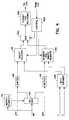
- Figure 4 is a block diagram of circuitry suitable for use in a digital VCR which records the high definition and low resolution signals provided by the television receivers shown in Figures 1 and 2.
- the multiplexed signal MV is applied in parallel to a demultiplexer 410 and to circuitry 412 which identifies the various data segments in the multiplexed data stream.
- the circuitry 412 identifies the segments by recognizing the main and auxiliary header words M HEAD and A HEAD.
- the circuitry 412 controls the demultiplexer 410, causing it to provide data representing the high resolution image to a buffer 416 and data representing the low resolution image to a buffer 414.
- the signals HRV and LRV representing the respective high resolution and low resolution images are provided in parallel, as in the circuitry shown in Figure 2, they may be received directly by the buffers 416 and 414, respectively, as shown by the broken-line signal paths in Figure 4.
- the demultiplexer 410 also acts to remove the headers M HEAD and A HEAD which were inserted by the multiplexer 130 shown in Figure 1. Consequently the data stream stored in the buffer 416 is the encoded HDTV signal 110 as shown in Figure 1. In the same manner the data values stored in the buffer 414 represent a reduced resolution video image which has been encoded using intra-frame coding techniques.
- the encoded low resolution signal provided by the buffer 414 is applied to a circuit 418 which segments the data into relatively small blocks, that may be fixed in length, and inserts header information at the start of each block.
- the data representing the low resolution signal is segmented such that the pixel values represented by each block may be reproduced without reference to any other block. If a segment is larger than needed to hold a compressed block, the remaining space in the segment is padded with dummy data values.
- the compressed low resolution segments may be variable in length up to a fixed maximum length. In this instance, the length of the low resolution segment may be stored in the segment header. As described below, if the encoded low-resolution segment is too long to be completely recovered by the tape head in trick-play mode, the pixel values represented by the missing data are reconstructed using conventional error concealment techniques.
- the data values representing the high resolution image are retrieved by circuitry 424 from the buffer 416.
- the circuitry 424 divides the data values into segments and, optionally, inserts header information at the start of each segment.
- each segment of the low resolution data desirably represents a portion of an image which may be decoded without reference to any other segment. That is to say, each segment of the low resolution data represents an independent slice of the low resolution image.
- the segments of the high resolution image are not so limited. Since data in these segments is recombined before the high resolution image is displayed, as described below with reference to Figure 5, a slice of the high resolution image may be split across multiple high resolution data segments.
- the segments produced by the circuitry 424 are applied to one signal input port of a multiplexer 420, the other signal input port of which is coupled to receive segments of the reduced resolution image provided by the circuitry 418.
- circuits 418, 420 and 424 are all under control of circuitry 428 which is responsive to signals provided by the VCR recorder (not shown) to alternately apply segments of the high definition and low resolution image data to achieve a predetermined pattern on the tape. Exemplary patterns are described below with reference to Figures 6, 7 and 8.
- the output signal of the multiplexer 420 is applied to circuitry 422 which formats the data values for recording.
- the circuitry 422 may include, for example, an error correction code (ECC) encoder (not shown), a channel encoder (not shown) and a recording amplifier (not shown).
- ECC error correction code
- control signals received by the circuitry 428 from the recording apparatus allow the encoder shown in Figure 4 to position the segments of the high resolution video information and the reduced resolution video information at predetermined locations in each track on the tape.
- the circuitry shown in Figure 4 allows high definition luminance (Y) signals and chrominance (C) signals to be encoded and recorded.
- the Y and C signals are produced, for example, by a high definition video camera, and are applied to an HDTV encoder 426.
- the output signal of the encoder 426 is applied as an alternate input to the circuitry 424 which segments the data and inserts header information.
- the HDTV encoder 426 uses only intra-frame encoding techniques.
- This circuitry also includes a second output port which provides a low resolution version of the image data.
- This image data may be provided, for example, by zeroing the high frequency coefficients in both the horizontal and vertical directions in the coefficient blocks produced by the discrete cosine transform circuitry (not shown) used in the HDTV encoder 426. After these high frequency coefficient values are zeroed, the resulting values would be quantized, run length coded, and variably length coded as in the MPEG standard.
- This low resolution output signal is applied as an alternate input to the circuitry 418 which inserts the header values in the low resolution image segments.
- the exemplary embodiment of the invention describes the HDTV encoder 426 as using only intra-frame encoding techniques, it is contemplated that the encoder may use both intra-frame and motion compensated encoding techniques. In this instance, the encoder 426 would also provide a low-resolution intra-frame encoded output signal to the circuitry 418.
- Figure 5 is a block diagram of circuitry in the VCR which recovers the data from the tape and provides either the high resolution HDTV signal or the low resolution signal for display, based on the position of a trick-play switch 538.
- circuitry 510 which decodes the data to reproduce digital values.
- the decoder circuitry 510 may include, for example, a head amplifier (not shown), a detector (not shown) and a ECC decoder (not shown). Digital values provided by the circuitry 510 are applied to a demultiplexer 522.
- the circuitry 510 provides signals to a circuit 520 which recognizes header information in the recorded data stream and identifies segments of the low resolution and high resolution image signals.
- the trick-play switch 536 may selectively disable either the high resolution or low resolution decoding circuitry.
- the segment identification information produced by the circuitry 520 is applied to control circuitry 524.
- the circuitry 524 produces an output signal which is applied to the control input terminal of demultiplexer 522. Responsive to this signal, demultiplexer 522 applies blocks of data representing the low resolution signal to circuitry 526 and blocks of data representing the high resolution image to circuitry 528. Under control of the circuitry 524 the circuit 526 deletes the header information from the low resolution encoded video data and applies the result to intra-frame decoding circuitry 532.
- the circuitry 532 reverses the intra-frame encoding which was performed by the circuitry, described above with reference to Figures 1 and 2, to produce low resolution luminance (Y L ) and chrominance (C L ) signals.
- This memory which is used to convert the blocks of data to raster form, may be identical to the memory 320 described above with reference to Figure 3. That is to say, it may contain only one-quarter of the pixel values that are contained in a conventional frame memory.
- the control circuitry 524 also controls the circuit 528 causing it to delete any header information which may have been appended to the segments of high definition encoded video signal.
- the circuitry 528 also recombines the segments of the high-resolution image into a data stream which is substantially identical to the received base band compressed video signal shown in Figures 1 and 2.
- the signal produced by the circuitry 528 is applied to an HDTV decoder 530 which processes it to produce full resolution luminance (Y H ) and chrominance (C H ) component HDTV signals.
- the signals Y L ' and C L ' which are retrieved from the partial frame memory 534, are applied to one pair of data input ports of a multiplexer 536 while the signals Y H and C H produced by the HDTV decoder 530 are applied to a second pair of signal input ports of the multiplexer 536.
- the multiplexer 536 is controlled by the trick-play switch 538 to provide the low resolution signals in trick-play display mode and to provide the high resolution signals in normal play mode.
- the low-resolution signal is provided from the memory 534, it may be expanded, for example, by repeating each pixel value and each line of pixel values to generate signals representing a full-sized image.
- FIG. 6 is a diagram of a segment of tape which shows an exemplary pattern for recording segments of high resolution and low resolution image data.
- the low resolution image data is represented by the shaded blocks, for example 620, 622 and 624 while the high resolution information is represented by the unshaded blocks for example 612, 614, 616 and 618.
- each of these blocks is shown as including two segments, a header segment (e.g. 612h) and a data segment (e.g. 612d).
- each of the low resolution image segments may also include a header segment.
- only one of the image segments may include header information so long as this header information includes the length of the segment. In this instance, the VCR would treat any data following the defined segment length as a segment of the other type until the next header is found.
- the high definition image data is contained in the data segments 612d, 614d, 616d and 618d.
- a conventional high resolution image data stream is produced.
- the low resolution segments 620 and 622 are interspersed among these high resolution data segments. During normal replay these segments are ignored by the VCR. In trick-play mode, however, when the tape head follows the path indicated by the arrow 611, only these segments are recovered.
- Figure 7 illustrates a segment of video tape in which only portions of each image frame are recorded for the low resolution signal.
- the low resolution data segments of the first nine tracks are used to record the top one-third of frame 1.
- the low resolution segments of the next nine tracks are used to record the middle one-third of frame 2 and the low resolution segments in the following sets of nine tracks are used to record the bottom one-third of frame 3 and then the top one-third of frame 4.
- FIG. 9 The image recovered in trick-play mode using the scheme shown in Figure 7 is illustrated in Figure 9.
- This Figure shows four successive images produced during trick-play mode.
- the top portion 910 of the first image is the top one-third of frame 1
- the middle portion 912 is the center portion of frame 2
- the bottom of the first image is the lower portion of frame 3.
- these portions of frames are taken from frame 4 - 916, frame 5 - 918 and frame 6 - 920.
- every third frame may be recorded in its entirety for recovery during trick-play mode.
- the low resolution image segments for frame 1 would be recorded across 27 consecutive tracks, the next 27 tracks would contain the low resolution image segments for frame 4.
- the successive frames 1010, 1012, 1014 and 1016 would correspond to frame 1, frame 4, frame 7 and frame 10 of the high resolution image.
- the reproduced image would appear to be increased in speed by a factor of three.
- Another aspect of the invention concerns the relative timing of the low resolution and high resolution images as they are recorded on tape.
- the low resolution image receives considerable processing in the television receiver while the high resolution is passed with relatively little processing. Accordingly, frames of the high resolution image may be recorded on the tape before corresponding frames at the low resolution image. Since the trick-play modes are generally perceived as providing only an approximate location on the tape, this difference in display timing should not be a problem.
- the low resolution signal may then be used as a preview signal for the high resolution signal. This may be useful for editing features in the VCR, allowing an operator, during normal play modes, to recover both high resolution and low resolution images and to view the low resolution versions of upcoming frames while transferring high resolution image data for the current frame.
- a delay of the type contemplated here may be implemented by increasing the size of the FIFO memory 124.
- the realignment of the main and auxiliary video signals may be implemented by inserting a delay element (not shown) in the path between the output of channel decoding circuitry 214 and signal HRV applied to the VCR.
Description
- The present invention concerns high definition television receivers and in particular a receiver which processes a received high definition video signal to produce data representing both a high resolution image and a low resolution image for recording by a VCR.
- Digital high definition television production schemes have been under development for several years. These schemes typically produce higher quality television images and sound than conventional television systems. To do this, these systems convey more information than is conveyed in a conventional television signal.
- Recent regulations issued by the Federal Communications Commission (FCC), however, require that this larger amount of information be sent within the same band of frequencies as a conventional television signal. To fit the relatively large bandwidth High Definition Television (HDTV) signal into a standard television channel, the information content of the HDTV signal must be compressed.
- Because of the relatively large degree of spatial redundancy and temporal redundancy in the HDTV signals, relatively high levels of data compression can be achieved for most television signals.
- One such compression method, by which spatial redundancy is removed from a television signal, generates discrete cosine transform representations of blocks of the image. This representation resolves an image frame into coefficient values representing its various spatial frequency components. Portions of an image which are the same from pixel to pixel or which exhibit a repetitive pattern are resolved from many pixel values to a relatively small number of frequency coefficient values. In addition, since the human eye is less sensitive to quantization errors in image components having high spatial frequencies than in image components having relatively low spatial frequencies, the high spatial frequency coefficients may be quantized more coarsely than the low spatial frequency coefficients to further reduce the amount of data used to represent the image.
- Temporal redundancy in an image may be removed by encoding only the areas of a given frame which are different from corresponding areas of a previously encoded frame. This is generally known as predictive coding. Temporal redundancy can be further exploited to achieve even higher levels of data compression by performing motion compensation. Using this scheme, before a image block is encoded, the blocks surrounding it in a previously encoded frame are searched for the one block which most closely matches the block in the current frame. The current block is then subtracted from the matching block in the previous frame and only the difference values are encoded.
- An exemplary video image compression system which employs motion-compensated predictive encoding techniques is that proposed by the Motion Picture Experts Group (MPEG) and described in the document entitled "Coded Representation of Picture and Audio Information" ISO-IEC/JTC1/SC2/WG11 N0010 MPEG 90/41 dated July 25, 1990.
- Other encoding techniques are also used in the MPEG system such as run-length coding, in which strings of identical values are encoded as a smaller number of values; and variable length coding, in which frequently occurring data values are assigned a digital code value having fewer bits than less frequently occurring data values.
- Whatever encoding technique is used the HDTV signal must be decoded before it can be displayed. For predictively encoded or motion compensated predictively encoded HDTV signals, the decoding apparatus may include one or more frame memories which hold images that have already been decoded. The pixel values held by these memories are used to reconstruct the predictively encoded data in the current frame.
- Using MPEG encoding techniques, HDTV signals having a data rate of between 600 and 1200 Megabits per second (Mbps) can be compressed to produce a signal having a data rate of less than 20 Mbps. As with other terrestrial broadcast signals, consumers will want to be able to receive, display and record signals representing high resolution video images with little no loss of resolution.
- On first analysis, the compression of HDTV signals should be beneficial for recording the signals on home use Video Cassette Recorders (VCR's), since these units typically have only a limited bandwidth available for recording video signals. For example, a paper by C. Yamamitsu et al. entitled "A Study on Trick-plays For Digital VCR", IEEE Transactions on Consumer Electronics, Volume 37, No. 3, August, 1991, PP. 261-266, discloses a home use VCR having a recording rate of 27 Megabits per second (Mbps). A typical HDTV signal, prior to encoding, has a bit-rate of 600 Mbps. Compression methods such as MPEG can reduce these HDTV signals to have a bit-rate of approximately 18 Mbps without noticeably degrading the image quality when the compressed signal is expanded.
- The problem with predictively encoded HDTV signals does not occur in recording or in normal playback modes but in trick-play modes such as fast-forward and reverse in which the video image is displayed at a higher rate than that at which it was recorded.
- The following is a description of the problem. Video information is recorded on a VCR in data blocks referred to as slices, which represent fixed-size portions of an image. As described above, some slices are encoded using intra-frame techniques while others are encoded using predictive techniques. The data blocks representing the slices are recorded as they occur in the video data stream. The amount of data in a slice may vary from slice-to-slice. This variation occurs because of the relative coding efficiencies of the slices in the original HDTV signal. Slices which represent still portions of a multi-frame image or which represent portions having relatively little variation may be encoded using a relatively small number of data values. Image portions containing a high level of detail and having no corresponding portions in previously encoded frames may require a significantly larger number of data values when they are encoded.
- When the image signals are read from the tape during normal playback each slice of each frame is read from the tape in sequence. If the coding method which produced the HDTV signals used predictive coding techniques the recorded data includes both intra-frame coded data and predictively coded data. In normal playback as the data is removed from the tape the pixel values for the intra-frame encoded portions are stored in a memory and are available for use in reconstructing the predicted frames.
- In a fast-forward trick-play mode, however, not all of the slices are recovered. If some of the slices that are not recovered are from an intra-coded frame, then their data values will not be available when corresponding predictively encoded slices are read from the tape. Consequently it may not be possible to properly reconstruct the predicted frame for display.
- Because of the difficulties of recovering predicted frames in trick-play modes most of the proposed methods for recording digitally compressed (bit-rate reduced) signals have restricted the encoding techniques that are used to encode data for recording on video tape recorders (VTR's), including VCR's, to exclude predicted frames. Exemplary systems of this type are described in an article by C. Yamamitsu, et al. entitled "An Experimental Study for a Home-Use Digital VTR", IEEE Transactions on Consumer Electronics, Volume 35, No. 3, August 1989, PP. 450-457, and in a paper by J. Lee et al., entitled "A Study on New DCT-Based Bit Rate Reduction Algorithm and Variable Speed Playback For A Home-Use Digital VCR", IEEE Transactions on Consumer Electronics, Volume 38, No. 3, August 1992, pp. 236 - 242. As described above, since these systems do not use predicted frames, they cannot compress data with the efficiency of a system, which does use predicted frames. Consequently, for the same compression ratios, they cannot achieve the same levels of detail in the reproduced image as a system, such as MPEG, which uses motion-compensated predictive coding techniques.
- EP-A-0 353 758 discloses a digital video recording apparatus, which receives uncoded video data, generates a compressed low-resolution version of selected frames of the received video data, compresses the received video data and records the generated low-resolution data with the compressed video data.
- EP-A-0 613 297, published on 31st August 1994, discloses a video tape recorder which receives an encoded and compressed high-resolution video signal, generates a compressed and encoded low-resolution version of the received signal and records the generated low-resolution signal with the high-resolution signal such that the low-resolution signal may be reproduced from the tape in trick-play modes such as fast forward and rewind.
- Furthermore, document US 4,845,564 discloses a television signal receiver comprising means for receiving a first encoded video signal; recording means for recording the first encoded video signal; first decoding means for decoding the first encoded video signal to produce a first decoded digital signal representing a first video image sequence; subsampling means, responsive to the first decoded digital signal, for generating a low-resolution video signal representing a reduced version of the entire first video mage sequence; output means for providing the first encoded video signal at the output terminal; means for receiving an encoded second video signal; means for decoding the encoded second video signal to produce a second decoded signal representing a second video image sequence; and means for multiplexing the second decoded signal and the low-resolution video signal to produce a composite signal representing the second video image sequence having the reduced resolution version of the first video image sequence as an inset.
- The present invention is embodied in a high-television receiver comprising means for receiving a first compressed and encoded high-definition video signal; first decoding means for decoding the first compressed and encoded high-definition video signal to produce a first decoded digital signal representing a first high-definition video image sequence; subsampling means, responsive to the first decoded digital signal, for generating a low-resolution video signal representing a reduced resolution version of the entire first high-definition video image sequence; means for compressing and encoding the low-resolution video signal to produce a compressed and encoded low-resolution video signal; output means for providing the first compressed an encoded high-definition video signal and the compressed and encoded low-resolution first video signal at an output terminal; means for receiving a second compressed and encoded high-definition video signal; means for decoding the compressed and encoded high-definition second video signal to produce a second decoded digital signal representing a second high-definition video image sequence; and means for mutiplexing the second decoded digital signal and the low-resolution video signal to produce a composite signal representing the second high-definition video image sequence having the reduced resolution version of the first high-definition video image sequence as an inset; further included being a video tape recorder including processing circuitry, coupled to receive the first compressed and encoded high-definition video signal and the compressed and encoded low-resolution video signal provided by the output means, the processing circuitry including means for separating each of the first compressed and encoded high-definition video signal and the compressed and encoded low-resolution video signal provided by the output means, the processing circuitry including means for separating each of the first compressed and encoded high-definition video signal and the compressed and encoded low-resolution video signal into respective segments; means for interleaving ones of the segments of the high-definition video signal with respective ones of the segments of the compressed and encoded low-resolution video signal to produce a combined signal; and means for formatting the combined signal for recording on a video tape recorder; the low resolution image data being also used by the television receiver to produce a picture-in-picture (PIP) display.
-
- Figure 1 is a block diagram of a television receiver which includes an exemplary embodiment of the invention.
- Figure 2 is a block diagram of a television receiver which includes an alternate embodiment of the invention.
- Figure 3 is a block diagram of a low resolution HDTV decoder suitable for use in the television receiver shown in Figure 2.
- Figure 4 is a block diagram of recording circuitry for a VCR suitable for use with the present invention.
- Figure 5 is a block diagram of replay circuitry for the VCR shown in Figure 4.
- Figure 6 is a graphical representation of a segment of video tape which is useful for explaining the VCR recording format used with the present invention.
- Figure 7 is a graphical depiction of a segment of video tape which is useful for describing a first sequencing of low resolution and high resolution image data in accordance with the present invention.
- Figure 8 is a graphical depiction of a segment of video tape which is useful for describing a second sequencing of low resolution and high resolution image data in accordance with the present invention.
- Figure 9 illustrates a group of image frames which would be produced using the data sequencing scheme shown in Figure 7.
- Figure 10 illustrates of a group of frames which would be produced using the data sequencing scheme shown in Figure 8.
-
- Each of the television receivers described below, which embody the present invention, produce two separate data streams. One data stream represents an HDTV video signal which has been encoded using both intra-frame and motion compensated encoding techniques. The second data stream represents a low resolution image which is sufficient for display in trick-play modes and which may be efficiently compressed to a relatively small number of data values using only intra-frame encoding techniques.
- The two data streams are provided by the television receiver either as a single multiplexed stream or as two independent streams. In the VCR, each of the data streams is separated into relatively small data segments which are time-division-multiplexed for recording on the tape. The segments of at least one of the data streams are identified by a header. In the exemplary embodiment of the invention, the low resolution segments have fixed minimum and maximum lengths and recorded at predetermined locations on the tape. These locations are selected to be in the path of the tape head during selected trick-play modes.
- Two alternative trick-play display modes are disclosed. In the first mode, a rotating segment from each frame is displayed to produce a complete image composed of different parts of each frame. In the second mode, images from single frames are displayed but only for selected frames in the sequence of frames (e.g. every third frame).
- Data representing the full compressed image is also recorded on the tape so that, in normal play modes, a complete high definition image may be recovered and displayed.
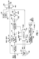
- Figure 1 is a block diagram of a television receiver in accordance with a first exemplary embodiment of the invention. In this embodiment, a digital data stream representing a baseband HDTV video signal is received at
terminal 110. This data stream may be provided, for example, by a television tuner (not shown) followed by a demodulator/decoder (not shown) which recovers a 32 state quadrature amplitude modulated (32-QAM) signal. - This data stream is applied in parallel to a
conventional HDTV decoder 112, a first-in-first-out (FIFO)memory 124 and to aclock generator 134. TheHDTV decoder 112 is the main decoder for the television receiver. If the HDTV video signal is encoded according to the motion-picture experts group (MPEG) standard, then theHDTV decoder 112 may include circuitry (not shown) to expand run length encoded and variable length encoded data, circuitry (not shown) to reverse the adaptive quantization applied in the MPEG encoding process, an inverse discrete cosine transform (IDCT) decoder (not shown), and a frame memory (not shown) for reversing any motion compensated encoding which may have been performed in the MPEG encoder. - The
exemplary HDTV encoder 112 produces blocks of pixel values representing a high definition video image. In this embodiment of the invention, these blocks may include 64 pixels arranged in an 8 x 8 matrix. - To produce a high definition television image, the blocks of pixel values are applied to a block to
raster converter 136. This circuit, which may include a frame memory buffer (not shown), produces pixel values in raster scan order which are applied to postprocessing circuitry 138. Thecircuitry 138 uses well known techniques to process the raster scan pixel values provided by thecircuitry 136 to generate analog red (R) green (G) and blue (B) signals and to regenerate horizontal and vertical synchronization signals (SYNC). These signals are used to drive a video display (not shown) to reproduce the high definition image sequence. - The blocks of pixel values provided by the
decoder 112 are also applied tocircuitry 114 which low pass filters and subsamples or decimates the blocks of pixel values to produce pixel values representing a reduced resolution image. In the exemplary embodiment of the invention the blocks of pixel values are subsampled by a factor of 1/2 in each of the horizontal and vertical directions. Accordingly, each block of 64 pixels which is applied to the filter and decimatecircuitry 114 produces a block of 16 pixels. The low-pass filter component of theblock 114 acts as an antialiasing filter. - These 16 pixel blocks reblocked into 64 pixel blocks which are applied to a discrete
cosine transform circuit 116. As in the MPEG encoding standard theDCT block 116 transforms the pixel values in each block into a block of coefficient values each representing a respectively different spatial frequency component of the block of pixel values. The blocks of coefficient values produced by theDCT 116 are applied toadaptive quantization circuitry 118. This circuitry adjusts the quantization resolution (i.e. number of bits) used to represent each of the DCT coefficients in response to a signal provided by acontroller 132. To generate this signal thecontroller 132 monitors the volume of data produced in the process of encoding the reduced resolution image. - After the adaptive quantization step, the quantized coefficient values are applied to a
variable length coder 120. Thecoder 120 includes both run length encoding circuitry, which reduces multiple identical data values to a smaller number of data values, and variable length encoding circuitry, which assigns shorter code words to more frequently occurring data values and longer code words to less frequently occurring data values. The output data values provided by the variablelength code circuity 120 are applied to aFIFO memory 122. - The data provided by the variable
length code circuitry 120 is inherently bursty. Data values are only provided when thecircuitry 120 has a block of data to encode and even then, the amount of data provided depends on the efficiency with which the circuitry can encode the data. - Data is entered into the FIFO memory using a clock signal BCK provided by the variable
length code circuitry 120. This signal has one pulse per data value during the bursts of data provided by thecoder 120. Data is read from theFifo 122 using an auxiliary read clock (ARCK) signal. - The high
definition video signal 110 is written into theFIFO memory 124 using a main write clock (MWCK) signal and read from theFIFO 124 using a main read clock (MRCK) signal. The signals MWCK and AWCK have substantially the same frequencies as do the signals RCK and WCK generated by theclock generator 134. - In the exemplary embodiment of the invention, the
clock generator 134 produces the write clock signal WCK having substantially the same frequency as the sampling clock signal used by theHDTV video signal 110 and produces the read clock signal RCK having a frequency determined by aresonant crystal 135. The signal MWCK is has the same frequency as the signal WCK and the signals MRCK and ARCK have the same frequency as the signal RCK. The difference in frequency between the signals WCK and RCK is related to the difference between the maximum data rate supported by the HDTV video signal and the maximum data rate which may be recorded on the digital VCR. - As described above the data rate for the HDTV video signal is approximately 18 MHz, while an exemplary data rate which may be recorded on the digital VCR is approximately 25 MHz. By speeding up the data stream representing the HDTV video signal from a data rate of 18 MHz to a data rate of 25 MHz, gaps are made available in the data stream for recording an auxiliary data stream representing the low resolution image.
- In the first exemplary embodiment of the invention, the
controller 132 determines when to switch between the main, HDTV video signal and the auxiliary, low resolution video signal. Thecontroller 132 monitors the main address (MAD) used to write data into theFIFO 124 and the auxiliary address (AAD) used to write data into theFIFO 122 in order to determine when to switch between the two data streams. The signal MAD indicates the space available in theFIFO 124 and the signal ADD indicates that a fixed-size block of low-resolution data is ready to be inserted into the data stream. When the signal MAD indicates that sufficient space exists in theFIFO 124 to store the largest number of HDTV signal that could be provided while the low-resolution block is added to the data stream, thecontroller 132 conditions themultiplexer 130 to switch to provide the low-resolution block. - In this instance, the
controller 132 first switches to provide, as its output signal MV, an auxiliary header word (A HEAD) fromdigital values source 128 and then to provide a block of digital values from theFIFO 122 at the read clock rate (ARCK). When the block of auxiliary video data has been provided thecontroller 132 switches back to the main video signal by first causing themultiplexer 132 to provide the main header word (M HEAD) from thedigital value source 126 and then to provide the contents of theFIFO 124 at the read clock rate (MRCK). Thus the output signal MV produced by themultiplexer 130 includes interleaved data blocks representing the main, high definition video signal and the auxiliary, reduced resolution video signal. This signal is processed by the VCR as described below with reference to Figure 4. - Figure 2 is a block diagram of a television receiver which includes an alternative embodiment of the present invention. This receiver includes two tuners so that the signal for one television program may be displayed on the video display device (not shown) while a signal for another television program is supplied to the VCR for recording, both in high definition and low definition modes. In addition the circuitry shown in Figure 2 allows the low definition video signal to be displayed as a small inset picture in the main video signal (i.e. as a part of a picture-in-picture display).
- In the circuitry shown in Figure 2, RF television signals, for example, from a wideband amplifier (not shown) are applied in parallel to a
main tuner 230 and to anauxiliary tuner 210.Tuner 230 selects the main television signal from the RF television signals and demodulates the main signal to produce a baseband modulated digital signal. The signal produced by thetuner 230 is applied to a 32QAM demodulator 232. Thedemodulator 232 produces a digital data stream from the baseband signal provided by thetuner 230. This signal is then applied tochannel decoding circuitry 234. - The
circuitry 234 may include, for example, error correction circuitry (not shown) as well as circuitry (not shown) which separates the audio, video and data signal components from the HDTV video signal. The video signal produced by thedecoding circuitry 234 is applied to aconventional HDTV decoder 236. This decoder may be identical to thedecoder 112 shown in Figure 1. - As described above, the output of the
HDTV decoder 236 are successive blocks of pixel values representing a high definition television image. These blocks are applied to one data input port of amultiplexer 238. The other input port of themultiplexer 238, as described below, is coupled to receive blocks of pixel values representing a low resolution image. - The
multiplexer 238 is controlled by a signal, PIP, to pass the high definition blocks from thedecoder 236 when a high definition image is to be displayed and to pass the low resolution blocks when a reduced resolution image (i.e. an inset picture-within-a-picture is to be displayed). The signal PIP may be generated by conventional circuitry (not shown) which controls the substitution of blocks of pixel values from the reduced resolution image for blocks of the high-definition image to produce a composite image in which the low-resolution image is displayed as an inset in the high-definition image. - The pixel blocks provided by the
multiplexer 238 are applied to a block toraster converter 240. As described above theconverter 240 transforms the blocks of pixel values into a sequence of data values representing a raster-scanned image. The values provided by theconverter 240 are applied to postprocessing circuitry 242. This circuitry may be identical to thepost processing circuitry 138 described above with reference to Figure 1. It produces R, G, B and SYNC signals which control the video display device to reproduce the HDTV image of the main channel with an inset picture from the auxiliary channel. - In the auxiliary channel the RF television signals are applied to a
tuner QAM demodulator 212 andchannel decoding circuitry 214 which may be identical to thecorresponding circuitry auxiliary tuner 210, however, may be different from that selected by thetuner 230. - The output signal of the
channel decoding circuitry 214 is a high resolution signal HRV which, as described below with reference to Figure 4, is applied to one of two parallel input ports of a digital VCR. This signal is also applied to a lowresolution HDTV decoder 216. Thedecoder 216 processes the video signal to produce blocks of samples representing a reduced resolution image. - In the exemplary embodiment of the invention, this low resolution image has approximately one-half the resolution of the HDTV image in both the vertical and horizontal directions. Exemplary circuitry suitable for use as the
decoder 216 is described below with reference to Figure 3. - The low resolution blocks of pixels produced by the
decoder 216 are applied to the second signal input terminal of themultiplexer 238 described above. These pixel blocks are also applied to a discretecosine transform processor 218. Thecircuit 218 generates blocks of coefficient values representing the magnitude of respectively different spatial frequency components of the reduced resolution image. - These coefficient values are then applied to a
quantizer 220 which encodes the coefficient values according to respectively different fixed quantization factors based on their respective spatial frequencies. In the exemplary embodiment of the invention, the higher the spatial frequency represented by the coefficient value the fewer number of bits are allowed to represent the value by thequantizer 220. - The quantized coefficients provided by the
circuitry 220 are then applied to avariable length coder 222. In the exemplary embodiment of the invention, this encoder may be identical to theencoder 120 described above. The output signal of theencoder 222 is the signal LRV which is applied to the second input port of the VCR. - It is noted that while the signal HRV may include both intra-frame encoded pixel values and predictively encoded pixel values, the signal LRV includes only intra-frame coded values. These values are easier to decode because they do not require corresponding values from a previous frame.
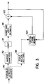
- Figure 3 is a block diagram of circuitry suitable for use as the low
resolution HDTV decoder 216 shown in Figure 2. In this circuitry the signal HRV is applied to avariable length decoder 310. Theexemplary decoder 310 which, in this exemplary embodiment of the invention assumes that the signal has been encoded according to the MPEG standard, reverses the variable length and run length coding operations. - The
decoder 310 produces two output signals, a decompressed digital data stream representing quantized DCT coefficients and data values representing motion vectors. The motion vectors are used to decode pixel values which were encoded using motion compensated encoding techniques. The quantized DCT coefficients are applied to aninverse quantizer 312. This quantizer reverses the adaptive quantization which was performed as part of the MPEG encoding algorithm. - The
inverse quantizer 312 produces blocks of data values representing respectively different spatial frequency components of the high definition television signals. These components are applied to inverse discretecosine transform circuity 314 which processes the coefficient values to reproduce the underlying pixel values. The blocks of pixel values provided by theinverse DCT circuitry 314 are applied tocircuitry 316 which decimates the blocks horizontally and vertically to reduce their resolution by a factor of one-half. The reduced pixel blocks provided by thecircuitry 316 are then applied to one input port of anadder 322. - The other input port of the adder is coupled to receive corresponding pixel values from a
partial frame memory 320, as determined by the motion vectors retrieved from the digital data stream by thevariable length decoder 310. In the exemplary embodiment of the invention, since the image blocks are decimated by one-half both vertically and horizontally, the motion vectors provided by thecircuitry 310 are scaled incircuitry 318 so that they will point to corresponding image data stored in thepartial frame memory 320. - Thus the blocks of pixel values provided by the
partial frame memory 320 correspond, to within the resolution of the scaled motion vectors, to the blocks of pixel values provided by thecircuitry 316. As described above, the motion vectors in the encoded data stream point to blocks of pixel values which serve as base values for blocks of pixel values that are encoded using motion-compensated differential encoding techniques. - Both the base blocks of pixel values and the decoded differential pixel values are summed by the
adder 322 to produce blocks of reduced resolution video image pixel values. These values are then stored in thepartial frame memory 320. As described above theadder 322 applies its output signal in parallel to theDCT circuitry 218 and to the second data input port of themultiplexer 238 as shown in Figure 2. - Figure 4 is a block diagram of circuitry suitable for use in a digital VCR which records the high definition and low resolution signals provided by the television receivers shown in Figures 1 and 2.
- If the signal is provided as a single multiplexed digital data stream, as in the television receiver shown in Figure 1, the multiplexed signal MV is applied in parallel to a
demultiplexer 410 and tocircuitry 412 which identifies the various data segments in the multiplexed data stream. Thecircuitry 412 identifies the segments by recognizing the main and auxiliary header words M HEAD and A HEAD. Thecircuitry 412 controls thedemultiplexer 410, causing it to provide data representing the high resolution image to abuffer 416 and data representing the low resolution image to abuffer 414. Alternatively, if the signals HRV and LRV representing the respective high resolution and low resolution images are provided in parallel, as in the circuitry shown in Figure 2, they may be received directly by thebuffers - In the exemplary embodiment of the invention the
demultiplexer 410 also acts to remove the headers M HEAD and A HEAD which were inserted by themultiplexer 130 shown in Figure 1. Consequently the data stream stored in thebuffer 416 is the encodedHDTV signal 110 as shown in Figure 1. In the same manner the data values stored in thebuffer 414 represent a reduced resolution video image which has been encoded using intra-frame coding techniques. - The encoded low resolution signal provided by the
buffer 414 is applied to acircuit 418 which segments the data into relatively small blocks, that may be fixed in length, and inserts header information at the start of each block. The data representing the low resolution signal is segmented such that the pixel values represented by each block may be reproduced without reference to any other block. If a segment is larger than needed to hold a compressed block, the remaining space in the segment is padded with dummy data values. Alternatively, the compressed low resolution segments may be variable in length up to a fixed maximum length. In this instance, the length of the low resolution segment may be stored in the segment header. As described below, if the encoded low-resolution segment is too long to be completely recovered by the tape head in trick-play mode, the pixel values represented by the missing data are reconstructed using conventional error concealment techniques. - The data values representing the high resolution image are retrieved by
circuitry 424 from thebuffer 416. Thecircuitry 424 divides the data values into segments and, optionally, inserts header information at the start of each segment. - In the exemplary embodiment of the invention each segment of the low resolution data desirably represents a portion of an image which may be decoded without reference to any other segment. That is to say, each segment of the low resolution data represents an independent slice of the low resolution image.
- The segments of the high resolution image are not so limited. Since data in these segments is recombined before the high resolution image is displayed, as described below with reference to Figure 5, a slice of the high resolution image may be split across multiple high resolution data segments. The segments produced by the
circuitry 424 are applied to one signal input port of amultiplexer 420, the other signal input port of which is coupled to receive segments of the reduced resolution image provided by thecircuitry 418. - The
circuits circuitry 428 which is responsive to signals provided by the VCR recorder (not shown) to alternately apply segments of the high definition and low resolution image data to achieve a predetermined pattern on the tape. Exemplary patterns are described below with reference to Figures 6, 7 and 8. - The output signal of the
multiplexer 420 is applied tocircuitry 422 which formats the data values for recording. Thecircuitry 422 may include, for example, an error correction code (ECC) encoder (not shown), a channel encoder (not shown) and a recording amplifier (not shown). - The control signals received by the
circuitry 428 from the recording apparatus allow the encoder shown in Figure 4 to position the segments of the high resolution video information and the reduced resolution video information at predetermined locations in each track on the tape. - In addition to recording externally supplied encoded HDTV signals, the circuitry shown in Figure 4 allows high definition luminance (Y) signals and chrominance (C) signals to be encoded and recorded. The Y and C signals are produced, for example, by a high definition video camera, and are applied to an
HDTV encoder 426. The output signal of theencoder 426 is applied as an alternate input to thecircuitry 424 which segments the data and inserts header information. - In the exemplary embodiment of the invention the
HDTV encoder 426 uses only intra-frame encoding techniques. This circuitry also includes a second output port which provides a low resolution version of the image data. This image data may be provided, for example, by zeroing the high frequency coefficients in both the horizontal and vertical directions in the coefficient blocks produced by the discrete cosine transform circuitry (not shown) used in theHDTV encoder 426. After these high frequency coefficient values are zeroed, the resulting values would be quantized, run length coded, and variably length coded as in the MPEG standard. This low resolution output signal is applied as an alternate input to thecircuitry 418 which inserts the header values in the low resolution image segments. - Although the exemplary embodiment of the invention describes the
HDTV encoder 426 as using only intra-frame encoding techniques, it is contemplated that the encoder may use both intra-frame and motion compensated encoding techniques. In this instance, theencoder 426 would also provide a low-resolution intra-frame encoded output signal to thecircuitry 418. - Figure 5 is a block diagram of circuitry in the VCR which recovers the data from the tape and provides either the high resolution HDTV signal or the low resolution signal for display, based on the position of a trick-
play switch 538. - In the processing circuitry shown in Figure 5, data from the tape is provided to
circuitry 510 which decodes the data to reproduce digital values. Thedecoder circuitry 510 may include, for example, a head amplifier (not shown), a detector (not shown) and a ECC decoder (not shown). Digital values provided by thecircuitry 510 are applied to ademultiplexer 522. In addition, thecircuitry 510 provides signals to acircuit 520 which recognizes header information in the recorded data stream and identifies segments of the low resolution and high resolution image signals. - In the exemplary embodiments of the invention, only the high resolution signals are processed for display in normal-play mode and only the low resolution signals are processed for display in trick-play mode. Accordingly, the trick-
play switch 536 may selectively disable either the high resolution or low resolution decoding circuitry. - The segment identification information produced by the
circuitry 520 is applied to controlcircuitry 524. Thecircuitry 524 produces an output signal which is applied to the control input terminal ofdemultiplexer 522. Responsive to this signal,demultiplexer 522 applies blocks of data representing the low resolution signal tocircuitry 526 and blocks of data representing the high resolution image tocircuitry 528. Under control of thecircuitry 524 thecircuit 526 deletes the header information from the low resolution encoded video data and applies the result tointra-frame decoding circuitry 532. Thecircuitry 532 reverses the intra-frame encoding which was performed by the circuitry, described above with reference to Figures 1 and 2, to produce low resolution luminance (YL) and chrominance (CL) signals. These signals are applied to a lowresolution frame memory 534. This memory, which is used to convert the blocks of data to raster form, may be identical to thememory 320 described above with reference to Figure 3. That is to say, it may contain only one-quarter of the pixel values that are contained in a conventional frame memory. - The
control circuitry 524 also controls thecircuit 528 causing it to delete any header information which may have been appended to the segments of high definition encoded video signal. Thecircuitry 528 also recombines the segments of the high-resolution image into a data stream which is substantially identical to the received base band compressed video signal shown in Figures 1 and 2. The signal produced by thecircuitry 528 is applied to anHDTV decoder 530 which processes it to produce full resolution luminance (YH) and chrominance (CH) component HDTV signals. - The signals YL' and CL', which are retrieved from the
partial frame memory 534, are applied to one pair of data input ports of amultiplexer 536 while the signals YH and CH produced by theHDTV decoder 530 are applied to a second pair of signal input ports of themultiplexer 536. Themultiplexer 536 is controlled by the trick-play switch 538 to provide the low resolution signals in trick-play display mode and to provide the high resolution signals in normal play mode. When the low-resolution signal is provided from thememory 534, it may be expanded, for example, by repeating each pixel value and each line of pixel values to generate signals representing a full-sized image. - Figure 6 is a diagram of a segment of tape which shows an exemplary pattern for recording segments of high resolution and low resolution image data. In Figure 6 as well as in Figures 7 and 8, the low resolution image data is represented by the shaded blocks, for example 620, 622 and 624 while the high resolution information is represented by the unshaded blocks for example 612, 614, 616 and 618. In Figure 6 each of these blocks is shown as including two segments, a header segment (e.g. 612h) and a data segment (e.g. 612d). Although it is not shown, in the exemplary embodiment of the invention each of the low resolution image segments may also include a header segment. Alternatively only one of the image segments may include header information so long as this header information includes the length of the segment. In this instance, the VCR would treat any data following the defined segment length as a segment of the other type until the next header is found.
- In Figure 6 the high definition image data is contained in the
data segments low resolution segments arrow 611, only these segments are recovered. - In the present invention, two methods of recording low resolution image information are contemplated. These are illustrated by Figures 7 and 9 on the one hand and by Figures 8 and 10 on the other hand. Figure 7 illustrates a segment of video tape in which only portions of each image frame are recorded for the low resolution signal. In Figure 7 the low resolution data segments of the first nine tracks are used to record the top one-third of frame 1. The low resolution segments of the next nine tracks are used to record the middle one-third of
frame 2 and the low resolution segments in the following sets of nine tracks are used to record the bottom one-third offrame 3 and then the top one-third offrame 4. - The image recovered in trick-play mode using the scheme shown in Figure 7 is illustrated in Figure 9. This Figure shows four successive images produced during trick-play mode. The top portion 910 of the first image is the top one-third of frame 1, the middle portion 912 is the center portion of
frame 2 and the bottom of the first image is the lower portion offrame 3. In the next succeeding image these portions of frames are taken from frame 4 - 916, frame 5 - 918 and frame 6 - 920. - Alternatively as shown in Figures 8 and 10, every third frame may be recorded in its entirety for recovery during trick-play mode. As shown in Figure 8, the low resolution image segments for frame 1 would be recorded across 27 consecutive tracks, the next 27 tracks would contain the low resolution image segments for
frame 4. As shown in Figure 10, during trick-play mode, the successive frames 1010, 1012, 1014 and 1016 would correspond to frame 1,frame 4, frame 7 and frame 10 of the high resolution image. During replay in trick-play mode, since only every third frame would be displayed, the reproduced image would appear to be increased in speed by a factor of three. - Another aspect of the invention concerns the relative timing of the low resolution and high resolution images as they are recorded on tape. In the embodiments described above the low resolution image receives considerable processing in the television receiver while the high resolution is passed with relatively little processing. Accordingly, frames of the high resolution image may be recorded on the tape before corresponding frames at the low resolution image. Since the trick-play modes are generally perceived as providing only an approximate location on the tape, this difference in display timing should not be a problem.
- It may be desirable however to modify this timing so that the low resolution image frames are recorded on the tape prior to the high resolution frames. The low resolution signal may then be used as a preview signal for the high resolution signal. This may be useful for editing features in the VCR, allowing an operator, during normal play modes, to recover both high resolution and low resolution images and to view the low resolution versions of upcoming frames while transferring high resolution image data for the current frame.
- With reference to Figure 1, a delay of the type contemplated here may be implemented by increasing the size of the
FIFO memory 124. In the embodiment of the invention shown in Figure 2, the realignment of the main and auxiliary video signals may be implemented by inserting a delay element (not shown) in the path between the output ofchannel decoding circuitry 214 and signal HRV applied to the VCR. - While the invention has been described in terms of an exemplary embodiment it is contemplated that it may be practiced as outlined above within the spirit and scope of the appended claims.
Claims (1)
- A high-definition television receiver comprising:means (210, 212, 214) for receiving a first compressed and encoded high-definition video signal;first decoding means (216, 310, 312, 314) for decoding the first compressed and encoded high-definition video signal to produce a first decoded digital signal representing a first high-definition video image sequence;subsampling means (316), responsive to the first decoded digital signal, for generating a low-resolution video signal representing a reduced resolution version of the entire first high-definition video image sequence;means (218, 220, 222) for compressing and encoding the low resolution video-signal to produce a compressed and encoded low-resolution video signal;output means (HRV, LRV) for providing the first compressed and encoded highdefinition video signal and the compressed and encoded low-resolution first video signal at an output terminal;means (230, 232, 234) for receiving a second compressed and encoded high-definition video signal;means (236) for decoding the compressed and encoded high-definition second video signal to produce a second decoded digital signal representing a second high-definition video image sequence; andmeans (238) for multiplexing the second decoded digital signal and the low-resolution video signal to produce a composite signal representing the second high-definition video image sequence having the reduced resolution version of the first high-definition video image sequence as an inset;a video tape recorder including processing circuitry (410, 412, 414, 416, 418, 420, 422, 424, 428), coupled to receive the first compressed and encoded high-definition video signal and the compressed and encoded low-resolution video signal provided by the output means, the processing circuitry including:means (410, 412, 414, 416, 424) for separating each of the first compressed and encoded high-definition video signal and the compressed and encoded low-resolution video signal into respective segments;means (420, 428) for interleaving ones of the segments of the high-definition video signal with respective ones of the segments of the compressed and encoded low-resolution video signal to produce a combined signal;means (422) for formatting the combined signal for recording on a video tape recorder.
Applications Claiming Priority (2)
| Application Number | Priority Date | Filing Date | Title |
|---|---|---|---|
| US08/073,789 US5477397A (en) | 1993-02-23 | 1993-06-08 | Digital high definition television receiver with features that facilitate trick-play modes on a digital VCR |
| US73789 | 1993-06-08 |
Publications (3)
| Publication Number | Publication Date |
|---|---|
| EP0629085A2 EP0629085A2 (en) | 1994-12-14 |
| EP0629085A3 EP0629085A3 (en) | 1995-04-12 |
| EP0629085B1 true EP0629085B1 (en) | 2000-08-02 |
Family
ID=22115813
Family Applications (1)
| Application Number | Title | Priority Date | Filing Date |
|---|---|---|---|
| EP94108312A Expired - Lifetime EP0629085B1 (en) | 1993-06-08 | 1994-05-30 | Digital high definition television receiver with features that facilitate trick-play modes on a digital vcr |
Country Status (6)
| Country | Link |
|---|---|
| US (1) | US5477397A (en) |
| EP (1) | EP0629085B1 (en) |
| JP (1) | JP3177383B2 (en) |
| KR (1) | KR100297538B1 (en) |
| CA (1) | CA2125334C (en) |
| DE (1) | DE69425401T2 (en) |
Families Citing this family (95)
| Publication number | Priority date | Publication date | Assignee | Title |
|---|---|---|---|---|
| DE69323338T2 (en) * | 1992-03-24 | 1999-06-10 | Toshiba Kawasaki Kk | Device for recording / reproducing codes of variable lengths for a video recorder |
| JP3290512B2 (en) * | 1992-08-24 | 2002-06-10 | 三菱電機株式会社 | Magnetic recording / reproducing device |
| US5623344A (en) * | 1992-09-01 | 1997-04-22 | Hitachi America, Ltd. | Digital video recording device with trick play capability |
| US5673358A (en) * | 1993-01-13 | 1997-09-30 | Hitachi America, Ltd. | Method for generating a reduced rate digital bitstream by selecting data as a function of the position within an image to which the data corresponds |
| US5726711A (en) * | 1993-01-13 | 1998-03-10 | Hitachi America, Ltd. | Intra-coded video frame data processing methods and apparatus |
| US5805762A (en) * | 1993-01-13 | 1998-09-08 | Hitachi America, Ltd. | Video recording device compatible transmitter |
| US5614952A (en) * | 1994-10-11 | 1997-03-25 | Hitachi America, Ltd. | Digital video decoder for decoding digital high definition and/or digital standard definition television signals |
| US5933567A (en) * | 1993-01-13 | 1999-08-03 | Hitachi America, Ltd. | Method and apparatus for controlling the position of the heads of a digital video tape recorder during trick play operation and for recording digital data on a tape |
| US5717816A (en) * | 1993-01-13 | 1998-02-10 | Hitachi America Ltd. | Method and apparatus for the selection of data for use in VTR trick playback operation in a system using intra-coded video frames |
| US5887115A (en) * | 1993-01-13 | 1999-03-23 | Hitachi America, Ltd. | Method and apparatus for implementing a video tape recorder for recording digital video signals having either a fixed or variable data transmission rate |
| JPH07153195A (en) * | 1993-11-30 | 1995-06-16 | Sony Corp | Digital recording device |
| EP0656729B1 (en) * | 1993-12-01 | 2000-02-09 | Matsushita Electric Industrial Co., Ltd. | Method and apparatus for editing or mixing compressed pictures |
| JPH07226917A (en) * | 1994-02-14 | 1995-08-22 | Toshiba Corp | Picture reproducing system and device therefor |
| US6115537A (en) * | 1994-02-18 | 2000-09-05 | Matsushita Electric Industrial Co., Ltd. | Digital signal recording and reproducing apparatus |
| JP3289045B2 (en) * | 1994-04-12 | 2002-06-04 | 三菱電機株式会社 | Digital recording and playback device |
| JP3089160B2 (en) * | 1994-05-20 | 2000-09-18 | シャープ株式会社 | Digital recording and playback device |
| US5592299A (en) * | 1994-09-26 | 1997-01-07 | Hitachi America, Ltd. | Method and apparatus for reducing the amount of data required to represent a video frame |
| US5841936A (en) * | 1994-10-07 | 1998-11-24 | Sony Corporation | Picture data recording/reproducing apparatus for providing divisional picture management without boundary distortion |
| US5828421A (en) * | 1994-10-11 | 1998-10-27 | Hitachi America, Ltd. | Implementation efficient digital picture-in-picture decoding methods and apparatus |
| US5867625A (en) * | 1994-10-20 | 1999-02-02 | Thomson Consumer Electronics, Inc. | Digital VCR with trick play steam derivation |
| JPH08140042A (en) * | 1994-11-07 | 1996-05-31 | Sony Corp | Reproducing device and recording and reproducing device for picture data |
| JPH08147479A (en) * | 1994-11-17 | 1996-06-07 | Hitachi Ltd | Image output device and image decoding device |
| KR0150702B1 (en) * | 1995-01-25 | 1998-10-15 | 구자홍 | Fast forward/reverse drive control method for vod system |
| US6137953A (en) * | 1995-05-23 | 2000-10-24 | Matsushita Electric Industrial Co., Ltd. | Video signal recording apparatus in which non-active digital video data may be recorded in an auxiliary data region |
| TW322238U (en) * | 1995-06-06 | 1997-12-01 | Nippon Steel Corp | A moving picture signal decoder |
| US5982982A (en) * | 1995-07-13 | 1999-11-09 | Matsushita Electric Industrial Co., Ltd. | Video signal processing apparatus |
| CN1091335C (en) * | 1995-08-22 | 2002-09-18 | 松下电器产业株式会社 | Video frequency signal processing device |
| WO1997026655A1 (en) * | 1996-01-19 | 1997-07-24 | Philips Electronics N.V. | Recording of a data reduced digital video signal in slant tracks on a record carrier |
| US5959690A (en) * | 1996-02-20 | 1999-09-28 | Sas Institute, Inc. | Method and apparatus for transitions and other special effects in digital motion video |
| US6445738B1 (en) * | 1996-04-25 | 2002-09-03 | Opentv, Inc. | System and method for creating trick play video streams from a compressed normal play video bitstream |
| US5825424A (en) * | 1996-06-19 | 1998-10-20 | Thomson Consumer Electronics, Inc. | MPEG system which decompresses and recompresses image data before storing image data in a memory and in accordance with a resolution of a display device |
| US5818530A (en) * | 1996-06-19 | 1998-10-06 | Thomson Consumer Electronics, Inc. | MPEG compatible decoder including a dual stage data reduction network |
| US5838838A (en) * | 1996-07-19 | 1998-11-17 | Hewlett-Packard Company | Down-scaling technique for bi-level images |
| SE515535C2 (en) * | 1996-10-25 | 2001-08-27 | Ericsson Telefon Ab L M | A transcoder |
| US6618443B1 (en) | 1997-03-12 | 2003-09-09 | Matsushita Electric Industrial Co., Ltd. | Upsampling filter for a down conversion system |
| US6184935B1 (en) * | 1997-03-12 | 2001-02-06 | Matsushita Electric Industrial, Co. Ltd. | Upsampling filter and half-pixel generator for an HDTV downconversion system |
| EP0899962A3 (en) * | 1997-08-26 | 2000-11-08 | Victor Company of Japan, Ltd. | Apparatus for recording a digital picture |
| US5929911A (en) * | 1997-10-27 | 1999-07-27 | International Business Machines Corporation | Multiformat reduced memory MPEG-2 compliant decoder |
| US5973740A (en) * | 1997-10-27 | 1999-10-26 | International Business Machines Corporation | Multi-format reduced memory video decoder with adjustable polyphase expansion filter |
| US6370192B1 (en) | 1997-11-20 | 2002-04-09 | Hitachi America, Ltd. | Methods and apparatus for decoding different portions of a video image at different resolutions |
| US6061400A (en) * | 1997-11-20 | 2000-05-09 | Hitachi America Ltd. | Methods and apparatus for detecting scene conditions likely to cause prediction errors in reduced resolution video decoders and for using the detected information |
| US6141456A (en) * | 1997-12-31 | 2000-10-31 | Hitachi America, Ltd. | Methods and apparatus for combining downsampling and inverse discrete cosine transform operations |
| US6122321A (en) * | 1998-05-12 | 2000-09-19 | Hitachi America, Ltd. | Methods and apparatus for reducing the complexity of inverse quantization operations |
| US6148032A (en) * | 1998-05-12 | 2000-11-14 | Hitachi America, Ltd. | Methods and apparatus for reducing the cost of video decoders |
| US6385248B1 (en) | 1998-05-12 | 2002-05-07 | Hitachi America Ltd. | Methods and apparatus for processing luminance and chrominance image data |
| US6456745B1 (en) * | 1998-09-16 | 2002-09-24 | Push Entertaiment Inc. | Method and apparatus for re-sizing and zooming images by operating directly on their digital transforms |
| US6487249B2 (en) | 1998-10-09 | 2002-11-26 | Matsushita Electric Industrial Co., Ltd. | Efficient down conversion system for 2:1 decimation |
| US7046910B2 (en) * | 1998-11-20 | 2006-05-16 | General Instrument Corporation | Methods and apparatus for transcoding progressive I-slice refreshed MPEG data streams to enable trick play mode features on a television appliance |
| US6570922B1 (en) * | 1998-11-24 | 2003-05-27 | General Instrument Corporation | Rate control for an MPEG transcoder without a priori knowledge of picture type |
| US6204887B1 (en) * | 1998-12-11 | 2001-03-20 | Hitachi America, Ltd. | Methods and apparatus for decoding and displaying multiple images using a common processor |
| US6434197B1 (en) | 1999-01-07 | 2002-08-13 | General Instrument Corporation | Multi-functional transcoder for compressed bit streams |
| FR2795279B1 (en) * | 1999-06-18 | 2001-07-20 | Thomson Multimedia Sa | METHOD AND DEVICE FOR SWITCHING DIGITAL TELEVISION PROGRAMS |
| US6275536B1 (en) | 1999-06-23 | 2001-08-14 | General Instrument Corporation | Implementation architectures of a multi-channel MPEG video transcoder using multiple programmable processors |
| US6532593B1 (en) * | 1999-08-17 | 2003-03-11 | General Instrument Corporation | Transcoding for consumer set-top storage application |
| MXPA02004488A (en) * | 1999-11-04 | 2002-09-02 | Thomson Licensing Sa | System and user interface for a television receiver in a television program distribution system. |
| JP4282201B2 (en) * | 2000-03-06 | 2009-06-17 | 株式会社東芝 | Encoded data recording device |
| BRPI0109291B1 (en) * | 2000-03-17 | 2015-06-23 | Thomson Licensing Sa | Method and apparatus for simultaneously recording and displaying a plurality of video signals from different video sources. |
| BR0109324A (en) * | 2000-03-17 | 2002-12-24 | Thomson Licensing Sa | Method and apparatus for simultaneously recording and displaying two different video programs |
| JP3569205B2 (en) * | 2000-06-09 | 2004-09-22 | シャープ株式会社 | Recording / playback device |
| US6647061B1 (en) * | 2000-06-09 | 2003-11-11 | General Instrument Corporation | Video size conversion and transcoding from MPEG-2 to MPEG-4 |
| EP1845723A3 (en) * | 2000-08-07 | 2008-11-12 | Sony Corporation | Information recording apparatus and method, information reading apparatus and method, magnetic tape format, and recording medium |
| US7039115B1 (en) | 2000-09-20 | 2006-05-02 | General Instrument Corporation | Processor allocation for channels in a video multi-processor system |
| US6847656B1 (en) | 2000-09-25 | 2005-01-25 | General Instrument Corporation | Statistical remultiplexing with bandwidth allocation among different transcoding channels |
| US6925501B2 (en) * | 2001-04-17 | 2005-08-02 | General Instrument Corporation | Multi-rate transcoder for digital streams |
| US7356245B2 (en) * | 2001-06-29 | 2008-04-08 | International Business Machines Corporation | Methods to facilitate efficient transmission and playback of digital information |
| US20030037330A1 (en) * | 2001-08-20 | 2003-02-20 | General Instrument Corporation | Methods and apparatus for the display of advertising material during personal versatile recorder trick play modes |
| KR100400353B1 (en) * | 2001-10-27 | 2003-10-04 | 엘지전자 주식회사 | Method and apparatus for transmitting digital contents |
| US7257664B2 (en) * | 2001-12-21 | 2007-08-14 | Lambert Everest Ltd. | Adaptive error resilience for signal transmission over a network |
| US7840119B2 (en) * | 2002-09-25 | 2010-11-23 | General Instrument Corporation | Methods and apparatus for processing progressive I-slice refreshed MPEG data streams to enable trick play mode features on a display device |
| US7226400B1 (en) | 2003-05-19 | 2007-06-05 | Maxime Gedeon-Janvier | Weight bench apparatus |
| US8213779B2 (en) * | 2003-09-07 | 2012-07-03 | Microsoft Corporation | Trick mode elementary stream and receiver system |
| US7924921B2 (en) * | 2003-09-07 | 2011-04-12 | Microsoft Corporation | Signaling coding and display options in entry point headers |
| US7839930B2 (en) * | 2003-11-13 | 2010-11-23 | Microsoft Corporation | Signaling valid entry points in a video stream |
| US9715898B2 (en) * | 2003-12-16 | 2017-07-25 | Core Wireless Licensing S.A.R.L. | Method and device for compressed-domain video editing |
| US7394974B2 (en) | 2004-01-26 | 2008-07-01 | Sony Corporation | System and method for associating presented digital content within recorded digital stream and method for its playback from precise location |
| US20070201828A1 (en) | 2004-04-02 | 2007-08-30 | Cheng Tao | Method and device for generating a menu |
| EP1878232A2 (en) * | 2005-04-26 | 2008-01-16 | Koninklijke Philips Electronics N.V. | A device for and a method of processing a data stream having a sequence of packets and timing information related to the packets |
| CN101248672A (en) * | 2005-08-26 | 2008-08-20 | 汤姆森特许公司 | Transcoding image for improved trick broadcast |
| US8428048B2 (en) | 2006-02-21 | 2013-04-23 | Qualcomm Incorporated | Multi-program viewing in a wireless apparatus |
| US8330866B2 (en) | 2006-02-21 | 2012-12-11 | Qualcomm Incorporated | Multi-program viewing in a wireless apparatus |
| US20070217761A1 (en) * | 2006-03-07 | 2007-09-20 | Coban Research And Technologies, Inc. | Method for video/audio recording using unrestricted pre-event/post-event buffering with multiple bit and frame rates buffer files |
| US20090077273A1 (en) * | 2007-09-18 | 2009-03-19 | Barinder Singh Rai | Control Data Transfer |
| KR101259015B1 (en) * | 2008-02-29 | 2013-04-29 | 삼성전자주식회사 | Reproducing method and apparatus |
| US8588299B1 (en) * | 2009-01-30 | 2013-11-19 | Hewlett-Packard Development Company, L.P. | Decoding video data |
| JP5890963B2 (en) | 2011-03-17 | 2016-03-22 | 富士通株式会社 | Data storage program and data storage method |
| KR20140063774A (en) | 2011-09-09 | 2014-05-27 | 파나몰프, 인코포레이티드 | Image processing system and method |
| US9544587B2 (en) | 2012-05-14 | 2017-01-10 | Google Technology Holdings LLC | Scalable video coding with enhanced base layer |
| JP5921469B2 (en) * | 2013-03-11 | 2016-05-24 | 株式会社東芝 | Information processing apparatus, cloud platform, information processing method and program thereof |
| US9307317B2 (en) | 2014-08-29 | 2016-04-05 | Coban Technologies, Inc. | Wireless programmable microphone apparatus and system for integrated surveillance system devices |
| US9225527B1 (en) | 2014-08-29 | 2015-12-29 | Coban Technologies, Inc. | Hidden plug-in storage drive for data integrity |
| US10165171B2 (en) | 2016-01-22 | 2018-12-25 | Coban Technologies, Inc. | Systems, apparatuses, and methods for controlling audiovisual apparatuses |
| US10152858B2 (en) | 2016-05-09 | 2018-12-11 | Coban Technologies, Inc. | Systems, apparatuses and methods for triggering actions based on data capture and characterization |
| US10370102B2 (en) | 2016-05-09 | 2019-08-06 | Coban Technologies, Inc. | Systems, apparatuses and methods for unmanned aerial vehicle |
| US10789840B2 (en) | 2016-05-09 | 2020-09-29 | Coban Technologies, Inc. | Systems, apparatuses and methods for detecting driving behavior and triggering actions based on detected driving behavior |
| JP7179746B2 (en) | 2017-04-19 | 2022-11-29 | フィリップ・モーリス・プロダクツ・ソシエテ・アノニム | Method for producing sheet-like tobacco material |
Citations (3)
| Publication number | Priority date | Publication date | Assignee | Title |
|---|---|---|---|---|
| US4845564A (en) * | 1987-04-16 | 1989-07-04 | Sony Corp. | Television receiver incorporating a video cassette recorder and capable of displaying a sub-channel picture within a main-channel picture |
| EP0353758A2 (en) * | 1988-08-05 | 1990-02-07 | Canon Kabushiki Kaisha | Video data recording apparatus for recording search data |
| EP0613297A2 (en) * | 1993-02-23 | 1994-08-31 | Matsushita Electric Industrial Co., Ltd. | Digital high definition television video recorder with trick-play features |
Family Cites Families (17)
| Publication number | Priority date | Publication date | Assignee | Title |
|---|---|---|---|---|
| US4730222A (en) * | 1985-04-22 | 1988-03-08 | Eastman Kodak Company | Video recording apparatus having low and high resolution operational modes |
| US4941055A (en) * | 1986-12-09 | 1990-07-10 | Canon Kabushiki Kaisha | Recording apparatus with improved S/N ratio |
| US4825301A (en) * | 1987-07-16 | 1989-04-25 | Polaroid Corporation | Apparatus for encoding and decoding high resolution still images and video images for recording on a standard storage media |
| JPS6477292A (en) * | 1987-09-18 | 1989-03-23 | Tamura Electric Works Ltd | Telephone system with holding function |
| IT1215909B (en) * | 1988-02-18 | 1990-02-22 | Rai Radiotelevisione Italiana | PROCEDURE FOR THE GENERATION AND TRANSMISSION OF HIGH-DEFINITION COLOR TELEVISION SIGNALS COMPATIBLE WITH THE CURRENT STANDARDS AND PROCEDURE AND RECEIVING EQUIPMENT FOR SIGNALS. |
| EP0352963A3 (en) * | 1988-07-28 | 1990-12-12 | British Broadcasting Corporation | Method of and apparatus for receiving high definition television signals |
| US5055927A (en) * | 1988-09-13 | 1991-10-08 | Deutsche Thomson-Brandt Gmbh | Dual channel video signal transmission system |
| US5136391A (en) * | 1988-11-02 | 1992-08-04 | Sanyo Electric Co., Ltd. | Digital video tape recorder capable of accurate image reproduction during high speed tape motion |
| KR920010043B1 (en) * | 1989-12-28 | 1992-11-13 | 삼성전자 주식회사 | Normal tv and hd-tv scene signal selection apparatus and method |
| JP3187852B2 (en) * | 1991-02-08 | 2001-07-16 | ソニー株式会社 | High efficiency coding method |
| US5260783A (en) * | 1991-02-21 | 1993-11-09 | Gte Laboratories Incorporated | Layered DCT video coder for packet switched ATM networks |
| US5122875A (en) * | 1991-02-27 | 1992-06-16 | General Electric Company | An HDTV compression system |
| JP2909239B2 (en) * | 1991-03-27 | 1999-06-23 | 株式会社東芝 | High-efficiency coded recording / reproducing device |
| JPH05130593A (en) * | 1991-11-05 | 1993-05-25 | Matsushita Electric Ind Co Ltd | Encoding device |
| JP3109185B2 (en) * | 1991-11-12 | 2000-11-13 | ソニー株式会社 | Digital VTR |
| US5262854A (en) * | 1992-02-21 | 1993-11-16 | Rca Thomson Licensing Corporation | Lower resolution HDTV receivers |
| JP3261844B2 (en) * | 1993-01-13 | 2002-03-04 | 株式会社日立製作所 | Digital video recording device and recording method |
-
1993
- 1993-06-08 US US08/073,789 patent/US5477397A/en not_active Expired - Fee Related
-
1994
- 1994-05-30 EP EP94108312A patent/EP0629085B1/en not_active Expired - Lifetime
- 1994-05-30 DE DE69425401T patent/DE69425401T2/en not_active Expired - Fee Related
- 1994-06-07 CA CA002125334A patent/CA2125334C/en not_active Expired - Fee Related
- 1994-06-08 JP JP12658694A patent/JP3177383B2/en not_active Expired - Fee Related
- 1994-06-08 KR KR1019940012800A patent/KR100297538B1/en not_active IP Right Cessation
Patent Citations (3)
| Publication number | Priority date | Publication date | Assignee | Title |
|---|---|---|---|---|
| US4845564A (en) * | 1987-04-16 | 1989-07-04 | Sony Corp. | Television receiver incorporating a video cassette recorder and capable of displaying a sub-channel picture within a main-channel picture |
| EP0353758A2 (en) * | 1988-08-05 | 1990-02-07 | Canon Kabushiki Kaisha | Video data recording apparatus for recording search data |
| EP0613297A2 (en) * | 1993-02-23 | 1994-08-31 | Matsushita Electric Industrial Co., Ltd. | Digital high definition television video recorder with trick-play features |
Also Published As
| Publication number | Publication date |
|---|---|
| CA2125334C (en) | 2004-06-01 |
| KR100297538B1 (en) | 2001-11-26 |
| DE69425401T2 (en) | 2001-01-11 |
| CA2125334A1 (en) | 1994-12-09 |
| US5477397A (en) | 1995-12-19 |
| JP3177383B2 (en) | 2001-06-18 |
| EP0629085A3 (en) | 1995-04-12 |
| EP0629085A2 (en) | 1994-12-14 |
| DE69425401D1 (en) | 2000-09-07 |
| KR950002453A (en) | 1995-01-04 |
| JPH0775112A (en) | 1995-03-17 |
Similar Documents
| Publication | Publication Date | Title |
|---|---|---|
| EP0629085B1 (en) | Digital high definition television receiver with features that facilitate trick-play modes on a digital vcr | |
| EP0613297B1 (en) | Digital high definition television video recorder with trick-play features | |
| RU2191469C2 (en) | Video transmitting device using intraframe video compression compatible with mpeg-2 code | |
| KR100326992B1 (en) | Digital Video Cassette Recorder with Trick Play Image Control | |
| US7526187B2 (en) | Processing digital data having variable packet lengths | |
| EP0691788A1 (en) | Variable length code recording/playback apparatus | |
| JPH089319A (en) | Method and device for recording and device for reproducing digital video signal | |
| JP3277713B2 (en) | Digital video signal recording device, recording / reproducing device, and reproducing device | |
| JP3107493B2 (en) | Digital high definition video recorder with high definition display in trick play mode | |
| JP3046226B2 (en) | Bit stream arrangement / restoration method for digital video tape recorder and data compression apparatus and decompression apparatus suitable for the method | |
| JP3133878B2 (en) | Data placement technology on tape of digital video tape recorder suitable for high-speed image reproduction | |
| EP0666692A2 (en) | Apparatus for recording and reproducing compressed or non-compressed digital video data | |
| US5526124A (en) | Image recording device, image reproducing device, image recording/reproducing device and image recording method | |
| JP3034172B2 (en) | Image data recording and playback device | |
| KR100286413B1 (en) | Video signal processing device | |
| JP3480517B2 (en) | Digital VTR | |
| JPH04337989A (en) | Image recording and reproducing device | |
| JPH0575969A (en) | Video signal recorder | |
| KR19980014895A (en) | The additional information recording and reproducing apparatus of the magnetic recording medium | |
| JPH089323A (en) | Recording method, recording device, recording medium, reproducing device and recording and recording device for digital video signal |
Legal Events
| Date | Code | Title | Description |
|---|---|---|---|
| PUAI | Public reference made under article 153(3) epc to a published international application that has entered the european phase |
Free format text: ORIGINAL CODE: 0009012 |
|
| AK | Designated contracting states |
Kind code of ref document: A2 Designated state(s): DE FR GB NL |
|
| PUAL | Search report despatched |
Free format text: ORIGINAL CODE: 0009013 |
|
| RAP1 | Party data changed (applicant data changed or rights of an application transferred) |
Owner name: MATSUSHITA ELECTRIC INDUSTRIAL CO., LTD. |
|
| AK | Designated contracting states |
Kind code of ref document: A3 Designated state(s): DE FR GB NL |
|
| 17P | Request for examination filed |
Effective date: 19950713 |
|
| 17Q | First examination report despatched |
Effective date: 19971113 |
|
| GRAG | Despatch of communication of intention to grant |
Free format text: ORIGINAL CODE: EPIDOS AGRA |
|
| GRAG | Despatch of communication of intention to grant |
Free format text: ORIGINAL CODE: EPIDOS AGRA |
|
| GRAH | Despatch of communication of intention to grant a patent |
Free format text: ORIGINAL CODE: EPIDOS IGRA |
|
| GRAH | Despatch of communication of intention to grant a patent |
Free format text: ORIGINAL CODE: EPIDOS IGRA |
|
| GRAA | (expected) grant |
Free format text: ORIGINAL CODE: 0009210 |
|
| AK | Designated contracting states |
Kind code of ref document: B1 Designated state(s): DE FR GB NL |
|
| PG25 | Lapsed in a contracting state [announced via postgrant information from national office to epo] |
Ref country code: NL Free format text: LAPSE BECAUSE OF FAILURE TO SUBMIT A TRANSLATION OF THE DESCRIPTION OR TO PAY THE FEE WITHIN THE PRESCRIBED TIME-LIMIT Effective date: 20000802 |
|
| REF | Corresponds to: |
Ref document number: 69425401 Country of ref document: DE Date of ref document: 20000907 |
|
| ET | Fr: translation filed | ||
| NLV1 | Nl: lapsed or annulled due to failure to fulfill the requirements of art. 29p and 29m of the patents act | ||
| PLBE | No opposition filed within time limit |
Free format text: ORIGINAL CODE: 0009261 |
|
| STAA | Information on the status of an ep patent application or granted ep patent |
Free format text: STATUS: NO OPPOSITION FILED WITHIN TIME LIMIT |
|
| 26N | No opposition filed | ||
| REG | Reference to a national code |
Ref country code: GB Ref legal event code: IF02 |
|
| PGFP | Annual fee paid to national office [announced via postgrant information from national office to epo] |
Ref country code: FR Payment date: 20040510 Year of fee payment: 11 |
|
| PGFP | Annual fee paid to national office [announced via postgrant information from national office to epo] |
Ref country code: GB Payment date: 20040526 Year of fee payment: 11 |
|
| PGFP | Annual fee paid to national office [announced via postgrant information from national office to epo] |
Ref country code: DE Payment date: 20040610 Year of fee payment: 11 |
|
| PG25 | Lapsed in a contracting state [announced via postgrant information from national office to epo] |
Ref country code: GB Free format text: LAPSE BECAUSE OF NON-PAYMENT OF DUE FEES Effective date: 20050530 |
|
| PG25 | Lapsed in a contracting state [announced via postgrant information from national office to epo] |
Ref country code: DE Free format text: LAPSE BECAUSE OF NON-PAYMENT OF DUE FEES Effective date: 20051201 |
|
| GBPC | Gb: european patent ceased through non-payment of renewal fee |
Effective date: 20050530 |
|
| PG25 | Lapsed in a contracting state [announced via postgrant information from national office to epo] |
Ref country code: FR Free format text: LAPSE BECAUSE OF NON-PAYMENT OF DUE FEES Effective date: 20060131 |
|
| REG | Reference to a national code |
Ref country code: FR Ref legal event code: ST Effective date: 20060131 |