EP0630660A1 - Seal assembly for accomodating introduction of surgical instruments - Google Patents
Seal assembly for accomodating introduction of surgical instruments Download PDFInfo
- Publication number
- EP0630660A1 EP0630660A1 EP94109086A EP94109086A EP0630660A1 EP 0630660 A1 EP0630660 A1 EP 0630660A1 EP 94109086 A EP94109086 A EP 94109086A EP 94109086 A EP94109086 A EP 94109086A EP 0630660 A1 EP0630660 A1 EP 0630660A1
- Authority
- EP
- European Patent Office
- Prior art keywords
- seal
- assembly
- seal assembly
- aperture
- bellows
- Prior art date
- Legal status (The legal status is an assumption and is not a legal conclusion. Google has not performed a legal analysis and makes no representation as to the accuracy of the status listed.)
- Granted
Links
Images


Classifications
-
- A—HUMAN NECESSITIES
- A61—MEDICAL OR VETERINARY SCIENCE; HYGIENE
- A61M—DEVICES FOR INTRODUCING MEDIA INTO, OR ONTO, THE BODY; DEVICES FOR TRANSDUCING BODY MEDIA OR FOR TAKING MEDIA FROM THE BODY; DEVICES FOR PRODUCING OR ENDING SLEEP OR STUPOR
- A61M39/00—Tubes, tube connectors, tube couplings, valves, access sites or the like, specially adapted for medical use
- A61M39/02—Access sites
- A61M39/06—Haemostasis valves, i.e. gaskets sealing around a needle, catheter or the like, closing on removal thereof
-
- A—HUMAN NECESSITIES
- A61—MEDICAL OR VETERINARY SCIENCE; HYGIENE
- A61B—DIAGNOSIS; SURGERY; IDENTIFICATION
- A61B17/00—Surgical instruments, devices or methods, e.g. tourniquets
- A61B17/34—Trocars; Puncturing needles
- A61B17/3462—Trocars; Puncturing needles with means for changing the diameter or the orientation of the entrance port of the cannula, e.g. for use with different-sized instruments, reduction ports, adapter seals
- A61B2017/3464—Trocars; Puncturing needles with means for changing the diameter or the orientation of the entrance port of the cannula, e.g. for use with different-sized instruments, reduction ports, adapter seals with means acting on inner surface of valve or seal for expanding or protecting, e.g. inner pivoting fingers
-
- A—HUMAN NECESSITIES
- A61—MEDICAL OR VETERINARY SCIENCE; HYGIENE
- A61M—DEVICES FOR INTRODUCING MEDIA INTO, OR ONTO, THE BODY; DEVICES FOR TRANSDUCING BODY MEDIA OR FOR TAKING MEDIA FROM THE BODY; DEVICES FOR PRODUCING OR ENDING SLEEP OR STUPOR
- A61M39/00—Tubes, tube connectors, tube couplings, valves, access sites or the like, specially adapted for medical use
- A61M39/02—Access sites
- A61M39/06—Haemostasis valves, i.e. gaskets sealing around a needle, catheter or the like, closing on removal thereof
- A61M2039/0626—Haemostasis valves, i.e. gaskets sealing around a needle, catheter or the like, closing on removal thereof used with other surgical instruments, e.g. endoscope, trocar
-
- A—HUMAN NECESSITIES
- A61—MEDICAL OR VETERINARY SCIENCE; HYGIENE
- A61M—DEVICES FOR INTRODUCING MEDIA INTO, OR ONTO, THE BODY; DEVICES FOR TRANSDUCING BODY MEDIA OR FOR TAKING MEDIA FROM THE BODY; DEVICES FOR PRODUCING OR ENDING SLEEP OR STUPOR
- A61M39/00—Tubes, tube connectors, tube couplings, valves, access sites or the like, specially adapted for medical use
- A61M39/02—Access sites
- A61M39/06—Haemostasis valves, i.e. gaskets sealing around a needle, catheter or the like, closing on removal thereof
- A61M2039/0633—Haemostasis valves, i.e. gaskets sealing around a needle, catheter or the like, closing on removal thereof the seal being a passive seal made of a resilient material with or without an opening
- A61M2039/0646—Duckbill-valve
-
- A—HUMAN NECESSITIES
- A61—MEDICAL OR VETERINARY SCIENCE; HYGIENE
- A61M—DEVICES FOR INTRODUCING MEDIA INTO, OR ONTO, THE BODY; DEVICES FOR TRANSDUCING BODY MEDIA OR FOR TAKING MEDIA FROM THE BODY; DEVICES FOR PRODUCING OR ENDING SLEEP OR STUPOR
- A61M39/00—Tubes, tube connectors, tube couplings, valves, access sites or the like, specially adapted for medical use
- A61M39/02—Access sites
- A61M39/06—Haemostasis valves, i.e. gaskets sealing around a needle, catheter or the like, closing on removal thereof
- A61M2039/0633—Haemostasis valves, i.e. gaskets sealing around a needle, catheter or the like, closing on removal thereof the seal being a passive seal made of a resilient material with or without an opening
- A61M2039/0666—Flap-valve
-
- A—HUMAN NECESSITIES
- A61—MEDICAL OR VETERINARY SCIENCE; HYGIENE
- A61M—DEVICES FOR INTRODUCING MEDIA INTO, OR ONTO, THE BODY; DEVICES FOR TRANSDUCING BODY MEDIA OR FOR TAKING MEDIA FROM THE BODY; DEVICES FOR PRODUCING OR ENDING SLEEP OR STUPOR
- A61M39/00—Tubes, tube connectors, tube couplings, valves, access sites or the like, specially adapted for medical use
- A61M39/02—Access sites
- A61M39/06—Haemostasis valves, i.e. gaskets sealing around a needle, catheter or the like, closing on removal thereof
- A61M2039/0686—Haemostasis valves, i.e. gaskets sealing around a needle, catheter or the like, closing on removal thereof comprising more than one seal
Definitions
- This invention relates to seal systems which are adapted to allow the introduction of surgical instrumentation into a patient's body.
- the invention is applicable to a cannula assembly wherein a cannula housing includes or is adapted to receive a seal assembly to sealingly accommodate instruments of different diameters inserted through the seal assembly and cannula.
- laparoscopic procedures surgery is performed in the interior of the abdomen through a small incision; in endoscopic procedures surgery is performed in any hollow viscus of the body through narrow tubes or cannula inserted through a small entrance incision in the skin.
- Laparoscopic and endoscopic procedures generally require that any instrumentation inserted into the body be sealed, i.e. provisions must be made to ensure that gases do not enter or exit the body through the incision as, for example, in surgical procedures in which the surgical region is insufflated.
- laparoscopic and endoscopic procedures often require the surgeon to act on organs, tissues, and vessels far removed from the incision, thereby requiring that any instruments used in such procedures be relatively long and narrow.
- a trocar assembly comprised of a cannula assembly and an obturator assembly. Since the cannula assembly provides a direct passage for surgical instrumentation from outside the patient's body to access internal organs and tissue, it is important that the cannula assembly maintain a relatively gas-tight interface between the abdominal cavity and the outside atmosphere.
- the cannula assembly thus generally includes a cannula attached to a cannula housing containing a seal assembly adapted to maintain a seal across the opening of the cannula housing.
- the procedure is usually initiated by use of a Verres needle through which a gas such as CO2 is introduced into the body cavity, thereby creating a pneumoperitoneum. Thereafter, the pointed obturator of the obturator assembly is inserted into the cannula assembly and used to puncture the abdominal wall.
- the gas provides a positive pressure which raises the inner body wall away from internal organs, thereby providing the surgeon with a region within which to operate and avoiding unnecessary contact with the organs by the instruments inserted through the cannula assembly.
- laparoscopic or endoscopic surgical instruments may be inserted through the cannula assembly to perform surgery within the abdominal cavity.
- the obturator assembly Without the obturator assembly to block the flow of insufflation gas out from the cavity, other structure must be provided to maintain a relatively fluid-tight interface between the abdominal cavity and the outside atmosphere.
- a pivotally mounted flapper valve may be provided which pivots open upon insertion of an instrument and pivots closed, under a spring bias, once the instrument is removed.
- Conventional flapper valves may also be manually opened by pivoting a lever provided on the exterior of the housing.
- An example of such a flapper valve is disclosed in U.S. Patent No. 4,943,280 to Lander. Trumpet valves are also well known for use in sealing a cannula assembly in the absence of a surgical instrument.
- U.S. Patent No. 4,655,752 to Honkanen et al. discloses a cannula including a housing and first and second seal members.
- the first seal member is conically tapered towards the bottom of the housing and has a circular opening in its center, while the second seal member is cup-shaped.
- the second seal member includes at least one slit to allow for passage of instruments.
- U.S. Patent No. 4,929,235 to Merry et al. discloses a self-sealing catheter introducer having a sealing mechanism to prevent blood or fluid leakage that includes a planar sealing element having a slit, and a conical sealing element distal of said planar sealing element so that if the distal conical sealing element is moved distally it rests upon the planar sealing element, each sealing element being adapted to surround a tube.
- U.S. Patent Nos. 4,874,377 and 5,064,416 to Newgard et al. relate to a self-occluding intravascular cannula assembly in which an elastomeric valving member is positioned transversely to a housing and is peripherally compressed to cause displacement, distortion and/or rheological flow of the elastomeric material.
- a frustoconical dilator projection is provided which cooperates with the elastomeric valving member in moving the valving member to a non-occluding position.
- U.S. Patent No. 5,104,3838 to Shichman relates to a trocar adapter seal which is adapted to be associated with a cannula assembly and which advantageously reduces the diameter of the cannula assembly to accommodate instruments of smaller diameter.
- the trocar adapter seal may be removed from the cannula assembly so that the cannula assembly may once again accommodate instruments of larger diameter.
- WO 93/04717 to Mueller et al. describes a similar trocar adapter seal system in which a pair of seal adapter plates are slidably mounted to the cannula housing and may be selectively positioned transverse the cannula housing aperture for accommodating surgical instrumentation therethrough.
- Cannula assemblies have also been developed which are provided with a series of resilient sealing elements having a central aperture, e.g., commonly assigned, co-pending applications EP 0 567 141 A2 and EP 0 567 142 A2.
- the sealing elements Upon insertion of an instrument, the sealing elements resiliently receive the instrument, while maintaining a seal around the instrument across a range of instrument diameters, e.g., 5 to 12mm.
- a fluid-tight seal is provided by the internal sealing elements.
- seal assemblies As part of or for use in conjunction with a cannula assembly which maintains the integrity of the seal between the body cavity and the atmosphere outside the patient's body, seal systems provided to date have failed to address the full range of surgeons' needs, especially when it is desired to utilize different instruments having different diameters therethrough.
- the present invention provides a seal assembly which will allow a surgeon to efficaciously utilize instruments of varying diameter in a surgical procedure.
- the seal assembly of the invention obviates the need for multiple adapters to accommodate instruments of varying diameter by providing a dilating funnel which is adapted to spread open the aperture of a seal member, thereby allowing the seal member to receive larger instrumentation with minimal force required on the part of the user.
- a seal assembly which comprises a housing and resilient first seal means associated with the housing, the first seal means having an aperture formed therein for receiving surgical instrumentation.
- the first seal means is a substantially planar, resilient gasket that is mounted transverse with respect to the housing.
- the seal assembly further includes dilating means associated with the housing for dilating the aperture of the first seal means.
- the first seal means and the dilating means are adapted for relative movement therebetween, such that the first seal means and the dilating means assume a first position wherein the aperture of the first seal means is spaced from the dilating means and is adapted to receive surgical instrumentation of a first diameter with minimal insertion force, i.e., less than about 2 lbs.
- the housing is adapted to be associated with a cannula assembly which includes a cannula housing and a tubular cannula.
- the cannula assembly may include a second seal means positioned within the cannula housing, such second seal means preferably comprising a distally directed duckbill member.
- the second seal means may also comprise a second substantially planar, resilient gasket that is mounted transverse with respect to the cannula housing, the aperture of the second resilient gasket being of larger diameter than the aperture of the resilient gasket found in the sealing assembly.
- the second seal means preferably provides a substantially fluid-tight seal in the absence of a surgical instrument passed therethrough.
- the housing of the seal assembly of the invention may comprise a bellows structure which is adapted to assume an extended position which corresponds to the first position of the first seal means and the dilating means, and a collapsed position which corresponds to the second position of the first seal means and the dilating means.
- the bellows structure may be encased within a rigid outer frame which defines a constant axial dimension for the seal assembly of the invention or, in the absence of such outer frame, movement of the bellows structure to the collapsed position may reduce the overall axial dimension of the seal assembly.
- the seal assembly may further comprise a flange associated with the bellows structure for moving the bellows structure between the extended position and the collapsed position.
- Biasing means e.g., a spring
- the resilience of the material from which the bellows structure and/or the first sealing means are fabricated may serve to bias the bellows structure to the extended position.
- a vent may also be provided between the interior of the bellows structure and the dilating means such that air within the bellows structure has a path of egress when the bellows structure is collapsed.
- the bellows structure preferably cooperates with adjoining structures to define a substantially fluid-tight region, with the exception of the vent described above.
- the second seal means positioned within the cannula assembly may include a substantially planar gasket.
- This gasket is preferably positioned proximal the distally directed duckbill member.
- the dilating means may include a proximally directed dilating funnel for spreading the gasket associated with the seal assembly of the invention and a distally directed member which is adapted to contact and expand the planar gasket of the second seal means for efficacious receipt of surgical instrumentation therethrough.
- the present invention contemplates the use of all types of endoscopic and laparoscopic surgical instruments therethrough including, but not limited to, clip appliers, surgical staplers, lasers, endoscopes, laparoscopes, forceps, photographic devices, graspers, dissectors, suturing devices, scissors, and the like. All of such devices are referred to herein as "instruments”.
- the seal assembly of the present invention provides a substantial seal between a body cavity of a patient and the outside atmosphere before, during and after insertion of an instrument through the cannula assembly.
- the seal assembly of the present invention is capable of accommodating instruments of varying diameters, e.g., from 5mm to 15mm, by providing a gas tight seal with each instrument when inserted.
- the flexibility of the present seal assembly greatly facilitates endoscopic surgery where a variety of instruments having differing diameters are often needed during a single surgical procedure.
- seal assembly 10 includes a housing in the form of bellows 12 having knurled collar 14 attached thereto by any suitable means such as adhesives, heat welding, etc.
- Bellows 12 is fabricated from a resilient material, e.g., isoprene, to facilitate the movements described hereinbelow and is preferably about 1 to about 4cm in axial dimension when at rest.
- Knurled collar 14 serves to adapt bellows 12 for removable attachment to cannula assembly 16.
- seal assembly 10 is detachably mounted to cannula assembly 16 through a bayonet attachment, and knurled collar 14 facilitates the rotation of seal assembly 10 relative to cannula assembly 16 in effectuating the bayonet attachment.
- Printed indicia 17 and 17A assist the surgeon in aligning knurled collar 14 with cannula assembly 16 and inclined cam surface 45 guides an internal projection (not pictured) on knurled collar 14 to flat 47, whereby seal assembly 10 is detachably mounted to cannula assembly 16.
- cannula assembly 16 includes a second inclined cam surface and flat on the opposite side thereof to cooperate with a second internal projection on knurled collar 14 to provide optimum stability to the interface between cannula assembly 16 and seal assembly 10.
- any suitable attaching means may be utilized, such as, for example, any quick connect mechanism.
- Seal assembly 10 further includes a first seal means, such as gasket 18, which is preferably fabricated from a resilient elastomeric material, e.g., isoprene.
- Gasket 18 is provided with aperture 20 formed centrally therethrough and preferably includes a proximally directed convolution which increase the flexibility and resilience thereof.
- Aperture 20 is preferably on the order of 4.5mm in diameter so that aperture 20 has a diameter which is less than the smallest diameter instrument which is likely to be utilized therethrough during the course of an endoscopic surgical procedure.
- Gasket 18 is securely affixed to bellows 12 so as to form a fluid tight seal along periphery 22.
- gasket 18 may be formed integrally with bellows 12 by known manufacturing processes, e.g., injection molding
- Seal assembly 10 may also include additional sealing structures, such as gasket member 24, which may serve a variety of purposes.
- gasket member 24 may simply function as a washer to ensure that seal assembly 10 is internally sealed.
- gasket member 24 may serve to sealingly engage instruments inserted through seal assembly 10 when aperture 20 of gasket 18 is stretched around the exterior face of dilator 28, as discussed below.
- Gasket member 24 is also preferably fabricated from a resilient elastomeric material, e.g., isoprene.
- An aperture 26 is formed through the center of gasket member 24 having a greater diameter than the diameter of aperture 20 in gasket 18.
- aperture 26 is preferably on the order of 9 to 10mm. In this way, gasket 24 will sealingly engage surgical instruments which are inserted through seal assembly 10 having a diameter of 9mm and greater.
- Seal assembly 10 further includes dilating means such as dilator 28 which is preferably made of a rigid polymeric material, e.g., ABS (acrylonitrile-butadienestyrene) or a suitable polycarbonate material.
- Dilator 28 has a passageway 30 formed therein which allows for passage of instruments therethrough.
- Flange 32 is formed at distal end 34 of dilator 28 and is configured and dimensioned for attachment to knurled collar 14, e.g, by an appropriate adhesive, sonic welding or the like.
- Inner wall 33 of dilator 28 is preferably of substantially uniform diameter, whereas the outer face 35 of dilator 28 preferably includes an inwardly tapered portion 39 at its proximal end.
- Inwardly tapered portion 39 facilitates interaction of dilator 28 with gasket 18 when dilator 28 acts to spread aperture 20 thereof.
- the inner diameter of dilator 28 is selected to accommodate free passage of the instrumentation to be used therethrough and is typically on the order of 13 to 14mm. Different internal diameters may be selected, however, based on the instrumentation seal assembly 10 is intended to accommodate.
- Dilator 28 also optionally includes vent 29 which permits gas communication therethrough. Vent 29 facilitates the collapse of bellows 12, as discussed below, by providing a path of egress for the air located between outer face 35 of dilator 28 and bellows 12.
- a plurality of vents may be circumferentially and/or axially spaced around dilator 28 to facilitate such air egress.
- cannula assembly 16 includes cannula housing 40 and cannula 42 which is attached thereto and which extends distally therefrom.
- Cannula assembly 16 preferably includes a second seal means, such as distally directed duckbill 44 mounted in interior region 46 of cannula housing 40.
- Duckbill 44 provides a substantially fluid-tight seal when communicating with an insufflated body cavity to substantially prevent escape of gases and fluids from inside the body cavity when no instrument is present in cannula assembly 16.
- Cannula assembly 16 also preferably includes a second gasket 49 fabricated from a resilient elastomeric material, e.g., isoprene. Second gasket 49 is provided with aperture 51 formed centrally therethrough.
- the diameter of aperture 51 may range widely, e.g. from 3mm to 15mm, based on the diameter of cannula 42 which defines the instrument sizes cannula assembly 16 is generally intended to accommodate.
- second gasket 49 is adapted to sealingly engage surgical instruments of greater diameter with respect thereto.
- seal assembly 10 Prior to insertion of a surgical instrument, such as instrument 48, duckbill member 44 provides a fluid-tight seal to cannula assembly 16.
- Seal assembly 10 is mounted to cannula assembly 16 and is in a first or at-rest position with bellows 12 fully extended in the axial direction as shown in Fig. 3. In this position, seal assembly 10 can receive surgical instrumentation having a diameter which closely corresponds to the diameter of aperture 20 in gasket 18 with minimal insertion force required.
- seal assembly 10 may receive surgical instruments of up to about 7mm with minimal insertion force.
- the insertion force required by the user with seal assembly 10 in the position shown in Fig. 3 increases substantially.
- flange 36 fabricated from a rigid polymeric material, e.g., ABS, is urged distally by the user, thereby translating gasket 18 with respect to dilator 28.
- This relative translation causes aperture 20 of gasket 18 to stretch around the inwardly tapered portion 39 of dilator 28, as shown in Fig. 4.
- This relative translation also causes bellows 12 to collapse and causes air egress through vent 29 into passage 30 of dilator 28, thereby preventing undesirable air compression in the region between dilator 28 and bellows 12 which would increase the force required to translate flange 36.
- gasket 18 allows distortion of a portion of gasket 18 to a substantially tubular orientation in conforming abutment with the outer face 35 of dilator 28.
- Instrument 48 can now be inserted through passage 30 within dilator 28 of seal assembly 10 and through cannula assembly 16 with minimal insertion force. Gasket member 24 and/or second gasket 49 sealingly engage instrument 48 as it passes therethrough.
- instrument 48 passes through duckbill member 44, a fluid-tight seal within cannula assembly 16 and seal assembly 16 is nonetheless ensured by the interaction between instrument 48 and gasket member 24 and/or second gasket 49.
- flange 36 may be released by the user.
- bellows 12 may resume its initial at-rest position (as shown in Fig. 3) without further impetus by the user.
- the user may raise flange 36 relative to cannula assembly 16, thereby inducing bellows 12 to resume its at-rest position. In either event, return of bellows 12 to its initial at-rest position allows gasket 18 to close around instrument 48, providing an ancillary fluid tight seal.
- gasket 18 and the presence of convolution 19 advantageously facilitate some degree of axial movement of instrument 48 with respect to seal assembly 10 without any translation of instrument 48 with respect to gasket 18. Rather, gasket 18 retains a fixed arcuate line of contact with instrument 48 by resiliently deflecting with the movement of instrument 48, alternately assuming convex and concave orientations with the axial movement of instrument 48. Thus, the resilience of gasket 18 together with the presence of convolution 19 reduces the force required for limited movements of instrument 48, while also serving to stabilize instrument 48 within seal assembly 10 and cannula assembly 16.
- a printed indicia may be provided on outer face 35 of dilator 28 to indicate the point at which bellows 12 is sufficiently collapsed to prevent its automatic return to its initial at-rest position.
- the user may simply urge flange 36 distally to the extent necessary to move gasket 18 below the printed indicia on the outer face 35 of dilator 28.
- bellows 12 is returned to its initial at-rest position and it is desired to remove instrument 48 from cannula assembly 16 and seal assembly 10, the user may repeat the steps described hereinabove to expand the diameter of aperture 20, thereby facilitating passage of instrument 48 with minimal force. Similarly, if it is desired to remove a specimen from within the body cavity, the user may repeat the steps described hereinabove to expand the diameter of aperture 20 to facilitate specimen passage.
- the user may also, if desired and in the absence of a surgical instrument inserted therethrough, detach seal assembly 10 from cannula assembly 16 at any point during the surgical procedure to advantageously employ surgical instruments through the low profile cannula assembly provided according to the invention.
- FIG. 5-7 Another embodiment of the seal assembly of the present invention is illustrated in Figs. 5-7.
- Seal assembly 110 is similar to seal assembly 10. Structures which are similar to structures in seal assembly 110 are designated with reference numerals similar to those of seal assembly 10 except a leading "1" has been added. With the exceptions noted below, operation of seal assembly 110, as shown in Figs. 6 and 7, is as described in connection with seal assembly 10 and Figs. 3 and 4 hereinabove.
- seal assembly 110 includes a rigid outer structure which comprises frame 150 which is preferably made of a ABS or a polycarbonate material.
- Frame 150 is in the form of a cage which is bounded at its proximal end by face 152 which is preferably bonded thereto, e.g., by an adhesive, sonic welding or the like.
- Frame 150 includes an annular base portion 154 to which dilator 128 is affixed, e.g., by an adhesive or sonic welding, and four rigid, proximally-directed arcuate portions 156, each having a notch 158 formed thereon.
- Flange 136 is provided with four arcuate slotted cut-outs 160 which may be cooperatively aligned with arcuate portions 156.
- Dilator 128 includes a substantially tubular, distally-directed extension 161 which extends distally beyond the annular base portion 154 of frame 150. Extension 161 serves to dilate aperture 151 of gasket member 149 when seal assembly 110 is mounted to cannula assembly 116. The dilation of aperture 151 by extension 161 further reduces the force required to introduce an instrument therethrough.
- extension 161 on dilator 128 militates in favor of returning bellows 112 to its initial at-rest position after an instrument is inserted therethrough so that gasket 118 may sealingly engage the shaft thereof. In that regard, bellows 112 is biased proximally toward its initial at-rest position by spring 162 and bearing ring 164.
- flange 136 When urged distally to collapse bellows 112 and expand aperture 120 of gasket 118 around dilator 128, flange 136 may be rotated clockwise, thereby locking flange 136 under notches 158 against the bias of spring 162, bearing ring 164, and the resilience of bellows 112 and gasket 118.
- the interaction between flange 136 and notches 158 of frame 150 provides an alternative means for maintaining bellows 112 in its collapsed position.
- the retention of any bellows of the present invention in a collapsed configuration may be advantageous if it is desired to utilize a surgical instrument within the body cavity without the shaft of the instrument being engaged by the gasket (18, 118).
- seal assembly 210 is illustrated in Figs. 8-10 as seal assembly 210 which is similar in certain respects to seal assemblies 10 and 110. Structures which are similar to corresponding structure in seal assemblies 10 and 110 are designated by the same numerals except that a leading "2" has been added for clarity and consistency.
- dilator 228 is movable relative to duckbill 244 which performs the assembly's sealing function.
- Other seal members may be provided in addition to or in place of duckbill 244, as for example, one or more gaskets as described hereinabove.
- Dilator 228 is provided with extended members 228a and 228b pivotably mounted thereto and tab portions 264 to facilitate movement of dilator 228 in a distal direction.
- Dilator 228 is biased in a proximal direction by spring 262 which bears against collar 266.
- Collar 266 also serves as a camming surface for extended members 228a and 228b during distal motion of dilator 228 as best be seen in Figs. 9 and 10.
- dilator 228 In operation, as illustrated in Figs. 9 and 10, when it is necessary or desirable to insert a large diameter instrument, e.g., an instrument having a diameter on the order of 7 to 15mm, dilator 228 is moved distally by advancing tabs 264 relative to cannula assembly 240. Extended members 228a and 228b contact collar 266 and are cammed thereby so that extended members 228a and 228b pivot to spread open the slit of duckbill 244 as illustrated in Fig. 10. Instrument 248 is then inserted through seal assembly 210 and tab portions 264 are released to allow duckbill 244 to close around instrument 248. As noted above, other seal configurations may be readily used to supplement or replace duckbill 244.
- a planar seal member having a central aperture or slit may be utilized in which event extended members 228a and 228b will serve to expand the size of the aperture or slit in the same manner as described for expanding the slit of duckbill 244.
- seal assembly 310 is illustrated in Fig. 11 as seal assembly 310 which is most closely related in structure and operation to seal assembly 110 of Figs. 5-7, described above.
- Seal assembly 310 differs from seal assembly 110 in that dilator 328 is conical and is fixed with respect to the frame 356.
- Gasket 318 is positioned distally of dilator 328 when seal assembly 310 is in its initial at-rest position and is adapted for axial movement with respect thereto.
- Additional bellows 313 is secured to seal carrier flange 365 at its proximal end and to the distal portion of frame 356 so as to form a fluid-tight passageway therewithin.
- seal carrier flange 365 is pulled proximally as shown in phantom lines in Fig. 11, thereby translating gasket with respect to dilator 328 and expanding aperture 320 therearound. Proximal translation of seal carrier flange serves to collapse bellows 312 while simultaneously axially extending additional bellows 313.
- seal assembly 410 which is incorporated in cannula housing sections 456a and 456b.
- a plurality of sealing elements such as overlapping sealing members 470 and conical gasket 472 are provided, as well as reinforcing and penetration prevention means such as conical members 474 which include overlapping tab portions for spreading and protecting gasket 472 .
- Members 476 preferably of an elastomeric material, are provided to substantially seal the interior passageway formed by the tubular extension of cannula housing sections 456a and 456b.
- Collar member 478 is provided and adapted for attachment to the distal end of cannula housing sections 456a and 456b.
- Dilator 428 includes ears 429 which extend through windows 480 formed in cannula housing sections 456a and 456b. When the surgeon desires to introduce an instrument of relatively large diameter, the surgeon may advance ears 429 and thus dilator 428 relative to cannula housing 456. Conical members 474 and gasket 472 which are positioned distal to dilator 428 are fixed with respect to cannula housing 456 and, therefore, distal movement of dilator 428 serves to dilate elements 474 and conical gasket 472.
Abstract
Description
- This invention relates to seal systems which are adapted to allow the introduction of surgical instrumentation into a patient's body. In particular, the invention is applicable to a cannula assembly wherein a cannula housing includes or is adapted to receive a seal assembly to sealingly accommodate instruments of different diameters inserted through the seal assembly and cannula.
- In laparoscopic procedures surgery is performed in the interior of the abdomen through a small incision; in endoscopic procedures surgery is performed in any hollow viscus of the body through narrow tubes or cannula inserted through a small entrance incision in the skin. Laparoscopic and endoscopic procedures generally require that any instrumentation inserted into the body be sealed, i.e. provisions must be made to ensure that gases do not enter or exit the body through the incision as, for example, in surgical procedures in which the surgical region is insufflated. Moreover, laparoscopic and endoscopic procedures often require the surgeon to act on organs, tissues, and vessels far removed from the incision, thereby requiring that any instruments used in such procedures be relatively long and narrow.
- For such procedures, the introduction of a tube into certain anatomical cavities such as the abdominal cavity is usually accomplished by use of a trocar assembly comprised of a cannula assembly and an obturator assembly. Since the cannula assembly provides a direct passage for surgical instrumentation from outside the patient's body to access internal organs and tissue, it is important that the cannula assembly maintain a relatively gas-tight interface between the abdominal cavity and the outside atmosphere. The cannula assembly thus generally includes a cannula attached to a cannula housing containing a seal assembly adapted to maintain a seal across the opening of the cannula housing.
- Since surgical procedures in the abdominal cavity of the body require insufflating gases to raise the cavity wall away from vital organs, the procedure is usually initiated by use of a Verres needle through which a gas such as CO2 is introduced into the body cavity, thereby creating a pneumoperitoneum. Thereafter, the pointed obturator of the obturator assembly is inserted into the cannula assembly and used to puncture the abdominal wall. The gas provides a positive pressure which raises the inner body wall away from internal organs, thereby providing the surgeon with a region within which to operate and avoiding unnecessary contact with the organs by the instruments inserted through the cannula assembly. Following removal of the obturator assembly from the cannula assembly, laparoscopic or endoscopic surgical instruments may be inserted through the cannula assembly to perform surgery within the abdominal cavity.
- Without the obturator assembly to block the flow of insufflation gas out from the cavity, other structure must be provided to maintain a relatively fluid-tight interface between the abdominal cavity and the outside atmosphere. Generally in the context of insufflatory surgical procedures, there are two sealing requirements for cannula assemblies. The first requirement is to provide a substantially fluid-tight seal when an instrument is not being introduced into or is not already present in the cannula. The second requirement is to provide a substantially fluid-tight seal when an instrument is being introduced into or is already present in the cannula. Additionally, as endoscopic and laparoscopic surgical procedures and techniques have advanced, it has become desirable to accommodate surgical instrumentation of varying outside diameters through a single cannula assembly in a given surgical procedure, thereby minimizing the number of cannulae required and facilitating efficiency in the surgical procedure.
- To meet the first sealing requirement, various seals have been provided for maintaining the pneumoperitoneum in the cavity when no trocar or other surgical instrument is present in the cannula. For example, a pivotally mounted flapper valve may be provided which pivots open upon insertion of an instrument and pivots closed, under a spring bias, once the instrument is removed. Conventional flapper valves may also be manually opened by pivoting a lever provided on the exterior of the housing. An example of such a flapper valve is disclosed in U.S. Patent No. 4,943,280 to Lander. Trumpet valves are also well known for use in sealing a cannula assembly in the absence of a surgical instrument.
- U.S. Patent No. 4,655,752 to Honkanen et al. discloses a cannula including a housing and first and second seal members. The first seal member is conically tapered towards the bottom of the housing and has a circular opening in its center, while the second seal member is cup-shaped. The second seal member includes at least one slit to allow for passage of instruments.
- U.S. Patent No. 4,929,235 to Merry et al. discloses a self-sealing catheter introducer having a sealing mechanism to prevent blood or fluid leakage that includes a planar sealing element having a slit, and a conical sealing element distal of said planar sealing element so that if the distal conical sealing element is moved distally it rests upon the planar sealing element, each sealing element being adapted to surround a tube.
- U.S. Patent Nos. 4,874,377 and 5,064,416 to Newgard et al. relate to a self-occluding intravascular cannula assembly in which an elastomeric valving member is positioned transversely to a housing and is peripherally compressed to cause displacement, distortion and/or rheological flow of the elastomeric material. A frustoconical dilator projection is provided which cooperates with the elastomeric valving member in moving the valving member to a non-occluding position.
- U.S. Patent No. 5,104,3838 to Shichman relates to a trocar adapter seal which is adapted to be associated with a cannula assembly and which advantageously reduces the diameter of the cannula assembly to accommodate instruments of smaller diameter. The trocar adapter seal may be removed from the cannula assembly so that the cannula assembly may once again accommodate instruments of larger diameter. WO 93/04717 to Mueller et al. describes a similar trocar adapter seal system in which a pair of seal adapter plates are slidably mounted to the cannula housing and may be selectively positioned transverse the cannula housing aperture for accommodating surgical instrumentation therethrough.
- Cannula assemblies have also been developed which are provided with a series of resilient sealing elements having a central aperture, e.g., commonly assigned, co-pending applications EP 0 567 141 A2 and EP 0 567 142 A2. Upon insertion of an instrument, the sealing elements resiliently receive the instrument, while maintaining a seal around the instrument across a range of instrument diameters, e.g., 5 to 12mm. Upon withdrawal of the instrument, a fluid-tight seal is provided by the internal sealing elements.
- Although attempts have been made to provide a seal assembly as part of or for use in conjunction with a cannula assembly which maintains the integrity of the seal between the body cavity and the atmosphere outside the patient's body, seal systems provided to date have failed to address the full range of surgeons' needs, especially when it is desired to utilize different instruments having different diameters therethrough.
- The present invention provides a seal assembly which will allow a surgeon to efficaciously utilize instruments of varying diameter in a surgical procedure. The seal assembly of the invention obviates the need for multiple adapters to accommodate instruments of varying diameter by providing a dilating funnel which is adapted to spread open the aperture of a seal member, thereby allowing the seal member to receive larger instrumentation with minimal force required on the part of the user.
- In accordance with the present invention a seal assembly is provided which comprises a housing and resilient first seal means associated with the housing, the first seal means having an aperture formed therein for receiving surgical instrumentation. In one embodiment, the first seal means is a substantially planar, resilient gasket that is mounted transverse with respect to the housing. The seal assembly further includes dilating means associated with the housing for dilating the aperture of the first seal means. The first seal means and the dilating means are adapted for relative movement therebetween, such that the first seal means and the dilating means assume a first position wherein the aperture of the first seal means is spaced from the dilating means and is adapted to receive surgical instrumentation of a first diameter with minimal insertion force, i.e., less than about 2 lbs. and preferably less than about 1 lb., and assume a second position wherein the aperture of the first seal means is stretched around the exterior face of the dilating means for receiving surgical instrumentation of a second diameter greater than the first diameter with minimal insertion force, i.e., less than about 2 lbs. and preferably less than about 1 lb.
- Preferably, the housing is adapted to be associated with a cannula assembly which includes a cannula housing and a tubular cannula. The cannula assembly may include a second seal means positioned within the cannula housing, such second seal means preferably comprising a distally directed duckbill member. The second seal means may also comprise a second substantially planar, resilient gasket that is mounted transverse with respect to the cannula housing, the aperture of the second resilient gasket being of larger diameter than the aperture of the resilient gasket found in the sealing assembly. The second seal means preferably provides a substantially fluid-tight seal in the absence of a surgical instrument passed therethrough. This substantial fluid-tight seal need only be provided, however, when the cannula assembly is introduced to an insufflated body cavity, in which case the positive pressure within the body cavity may force the distal faces of the preferred duckbill member into sealing abutment with each other.
- The housing of the seal assembly of the invention may comprise a bellows structure which is adapted to assume an extended position which corresponds to the first position of the first seal means and the dilating means, and a collapsed position which corresponds to the second position of the first seal means and the dilating means. The bellows structure may be encased within a rigid outer frame which defines a constant axial dimension for the seal assembly of the invention or, in the absence of such outer frame, movement of the bellows structure to the collapsed position may reduce the overall axial dimension of the seal assembly. The seal assembly may further comprise a flange associated with the bellows structure for moving the bellows structure between the extended position and the collapsed position. Biasing means, e.g., a spring, may be provided for biasing the bellows structure to the extended position. Alternatively, the resilience of the material from which the bellows structure and/or the first sealing means are fabricated may serve to bias the bellows structure to the extended position. A vent may also be provided between the interior of the bellows structure and the dilating means such that air within the bellows structure has a path of egress when the bellows structure is collapsed. To prevent unacceptable gas leakage from the insufflated body cavity when such vent is provided, the bellows structure preferably cooperates with adjoining structures to define a substantially fluid-tight region, with the exception of the vent described above.
- As noted above, the second seal means positioned within the cannula assembly may include a substantially planar gasket. This gasket is preferably positioned proximal the distally directed duckbill member. In such case, the dilating means may include a proximally directed dilating funnel for spreading the gasket associated with the seal assembly of the invention and a distally directed member which is adapted to contact and expand the planar gasket of the second seal means for efficacious receipt of surgical instrumentation therethrough.
- The foregoing features of the present invention will become more readily apparent and will be better understood by referring to the following detailed description of preferred embodiments of the invention, which are described hereinbelow with reference to the drawings wherein:
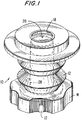
- Fig. 1 is a perspective view of one embodiment of the seal assembly of the present invention;
- Fig. 2 is an exploded view with parts separated of the embodiment of Fig. 1;
- Fig. 2A is an exploded view with parts separated of a portion of a cannula assembly which is adapted to be associated with the seal assembly of Fig. 2;
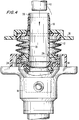
- Fig. 3 is a partial cross-sectional view of the seal assembly illustrated in Figs. 1 and 2 associated with the cannula assembly of Fig. 2A, which shows a seal member of the present invention in a non-dilated position;
- Fig. 4 is a partial cross-sectional view of the seal assembly similar to Fig. 3, except that the flange of the seal assembly is shown depressed so that the aperture of the seal member is dilated to the size of the opening of the dilator member;
- Fig. 5 is an exploded view with parts separated of another embodiment of the seal assembly of the present invention;
- Fig. 5A is an exploded view with parts separated of a portion of a cannula assembly which is adapted to be associated with the seal assembly of Fig. 5;
- Fig. 6 is a partial cross-sectional view of the embodiment of Fig. 5, which shows a seal member of the embodiment in a non-dilated position;
- Fig. 7 is a partial cross-sectional view of the embodiment of Fig. 5, which shows the flange of the seal assembly depressed so that the aperture of the seal member is dilated to the size of the opening of the dilator member;
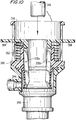
- Fig. 8 is an exploded view with parts separated of another embodiment of the seal assembly of the present invention;
- Fig. 9 is a partial cross-sectional view of the embodiment of Fig. 8, which shows a seal member of the embodiment in a non-dilated position;
- Fig. 10 is a partial cross-sectional view of the embodiment of Fig. 8, which shows the flange of the seal assembly depressed so that the aperture of the seal member is dilated by the pivoting dilator members;
- Fig. 11 is a cross-sectional view of another embodiment of the seal assembly of the present invention;
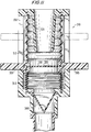
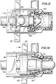
- Fig. 12 is an exploded view with parts separated of another embodiment of the seal assembly of the present invention; and
- Figs. 13 and 14 are progressive partial cross-sectional views of the embodiment of the seal assembly of Fig. 12, which show the operation of the seal assembly as a surgical instrument is inserted therein.
- The present invention contemplates the use of all types of endoscopic and laparoscopic surgical instruments therethrough including, but not limited to, clip appliers, surgical staplers, lasers, endoscopes, laparoscopes, forceps, photographic devices, graspers, dissectors, suturing devices, scissors, and the like. All of such devices are referred to herein as "instruments".
- The seal assembly of the present invention, either alone or in combination with a seal system internal to a cannula assembly, provides a substantial seal between a body cavity of a patient and the outside atmosphere before, during and after insertion of an instrument through the cannula assembly. Moreover, the seal assembly of the present invention is capable of accommodating instruments of varying diameters, e.g., from 5mm to 15mm, by providing a gas tight seal with each instrument when inserted. The flexibility of the present seal assembly greatly facilitates endoscopic surgery where a variety of instruments having differing diameters are often needed during a single surgical procedure.
- Referring to the drawings, in which like reference numerals identify identical or similar elements, Figs. 1-4 illustrate a preferred embodiment of the seal assembly of the present invention. Referring initially to Fig. 1 in conjunction with Figs. 2 and 2A,
seal assembly 10 includes a housing in the form ofbellows 12 havingknurled collar 14 attached thereto by any suitable means such as adhesives, heat welding, etc.Bellows 12 is fabricated from a resilient material, e.g., isoprene, to facilitate the movements described hereinbelow and is preferably about 1 to about 4cm in axial dimension when at rest. -
Knurled collar 14 serves to adaptbellows 12 for removable attachment tocannula assembly 16. In a preferred embodiment of the invention,seal assembly 10 is detachably mounted tocannula assembly 16 through a bayonet attachment, andknurled collar 14 facilitates the rotation ofseal assembly 10 relative tocannula assembly 16 in effectuating the bayonet attachment. Printedindicia knurled collar 14 withcannula assembly 16 andinclined cam surface 45 guides an internal projection (not pictured) onknurled collar 14 to flat 47, wherebyseal assembly 10 is detachably mounted tocannula assembly 16. Preferably,cannula assembly 16 includes a second inclined cam surface and flat on the opposite side thereof to cooperate with a second internal projection onknurled collar 14 to provide optimum stability to the interface betweencannula assembly 16 andseal assembly 10. However, any suitable attaching means may be utilized, such as, for example, any quick connect mechanism. -
Seal assembly 10 further includes a first seal means, such asgasket 18, which is preferably fabricated from a resilient elastomeric material, e.g., isoprene.Gasket 18 is provided withaperture 20 formed centrally therethrough and preferably includes a proximally directed convolution which increase the flexibility and resilience thereof.Aperture 20 is preferably on the order of 4.5mm in diameter so thataperture 20 has a diameter which is less than the smallest diameter instrument which is likely to be utilized therethrough during the course of an endoscopic surgical procedure.Gasket 18 is securely affixed tobellows 12 so as to form a fluid tight seal alongperiphery 22. Alternatively,gasket 18 may be formed integrally withbellows 12 by known manufacturing processes, e.g., injection molding -
Seal assembly 10 may also include additional sealing structures, such asgasket member 24, which may serve a variety of purposes. For example,gasket member 24 may simply function as a washer to ensure thatseal assembly 10 is internally sealed. Alternatively,gasket member 24 may serve to sealingly engage instruments inserted throughseal assembly 10 whenaperture 20 ofgasket 18 is stretched around the exterior face ofdilator 28, as discussed below.Gasket member 24 is also preferably fabricated from a resilient elastomeric material, e.g., isoprene. Anaperture 26 is formed through the center ofgasket member 24 having a greater diameter than the diameter ofaperture 20 ingasket 18. For example, ifgasket member 24 is intended to sealing engage instruments passed therethrough and ifaperture 20 is on the order of 4.5mm,aperture 26 is preferably on the order of 9 to 10mm. In this way,gasket 24 will sealingly engage surgical instruments which are inserted throughseal assembly 10 having a diameter of 9mm and greater. -
Seal assembly 10 further includes dilating means such asdilator 28 which is preferably made of a rigid polymeric material, e.g., ABS (acrylonitrile-butadienestyrene) or a suitable polycarbonate material.Dilator 28 has apassageway 30 formed therein which allows for passage of instruments therethrough.Flange 32 is formed at distal end 34 ofdilator 28 and is configured and dimensioned for attachment to knurledcollar 14, e.g, by an appropriate adhesive, sonic welding or the like.Inner wall 33 ofdilator 28 is preferably of substantially uniform diameter, whereas theouter face 35 ofdilator 28 preferably includes an inwardly taperedportion 39 at its proximal end. Inwardly taperedportion 39 facilitates interaction ofdilator 28 withgasket 18 whendilator 28 acts to spreadaperture 20 thereof. The inner diameter ofdilator 28 is selected to accommodate free passage of the instrumentation to be used therethrough and is typically on the order of 13 to 14mm. Different internal diameters may be selected, however, based on theinstrumentation seal assembly 10 is intended to accommodate.Dilator 28 also optionally includesvent 29 which permits gas communication therethrough.Vent 29 facilitates the collapse ofbellows 12, as discussed below, by providing a path of egress for the air located betweenouter face 35 ofdilator 28 and bellows 12. Optionally, a plurality of vents may be circumferentially and/or axially spaced arounddilator 28 to facilitate such air egress. - Referring to Fig. 2A,
cannula assembly 16 includescannula housing 40 andcannula 42 which is attached thereto and which extends distally therefrom.Cannula assembly 16 preferably includes a second seal means, such as distally directedduckbill 44 mounted ininterior region 46 ofcannula housing 40.Duckbill 44 provides a substantially fluid-tight seal when communicating with an insufflated body cavity to substantially prevent escape of gases and fluids from inside the body cavity when no instrument is present incannula assembly 16.Cannula assembly 16 also preferably includes asecond gasket 49 fabricated from a resilient elastomeric material, e.g., isoprene.Second gasket 49 is provided withaperture 51 formed centrally therethrough. The diameter ofaperture 51 may range widely, e.g. from 3mm to 15mm, based on the diameter ofcannula 42 which defines the instrumentsizes cannula assembly 16 is generally intended to accommodate. Depending on the diameter ofaperture 51,second gasket 49 is adapted to sealingly engage surgical instruments of greater diameter with respect thereto. - The operation of
seal assembly 10 in conjunction withcannula assembly 16 will now be described with reference to Figs. 3 and 4. Prior to insertion of a surgical instrument, such asinstrument 48,duckbill member 44 provides a fluid-tight seal tocannula assembly 16.Seal assembly 10 is mounted tocannula assembly 16 and is in a first or at-rest position withbellows 12 fully extended in the axial direction as shown in Fig. 3. In this position,seal assembly 10 can receive surgical instrumentation having a diameter which closely corresponds to the diameter ofaperture 20 ingasket 18 with minimal insertion force required. Thus, if the diameter ofaperture 20 is on the order of 4.5mm,seal assembly 10 may receive surgical instruments of up to about 7mm with minimal insertion force. However, with larger diameter instruments, e.g., instruments on the order of 10 to 12mm in diameter, the insertion force required by the user withseal assembly 10 in the position shown in Fig. 3 increases substantially. - To reduce the force required to introduce such a
larger diameter instrument 48 throughaperture 20,flange 36 fabricated from a rigid polymeric material, e.g., ABS, is urged distally by the user, thereby translatinggasket 18 with respect todilator 28. This relative translation causesaperture 20 ofgasket 18 to stretch around the inwardly taperedportion 39 ofdilator 28, as shown in Fig. 4. This relative translation also causes bellows 12 to collapse and causes air egress throughvent 29 intopassage 30 ofdilator 28, thereby preventing undesirable air compression in the region betweendilator 28 and bellows 12 which would increase the force required to translateflange 36. As shown in Fig. 4, the resilience ofgasket 18 allows distortion of a portion ofgasket 18 to a substantially tubular orientation in conforming abutment with theouter face 35 ofdilator 28.Instrument 48 can now be inserted throughpassage 30 withindilator 28 ofseal assembly 10 and throughcannula assembly 16 with minimal insertion force.Gasket member 24 and/orsecond gasket 49 sealingly engageinstrument 48 as it passes therethrough. Thus, at thepoint instrument 48 passes throughduckbill member 44, a fluid-tight seal withincannula assembly 16 andseal assembly 16 is nonetheless ensured by the interaction betweeninstrument 48 andgasket member 24 and/orsecond gasket 49. - Once
instrument 48 is inserted throughdilator 28,flange 36 may be released by the user. Depending on the degree to which bellows 12 was collapsed and the degree of resilience ofgasket 20 and bellows 12, bellows 12 may resume its initial at-rest position (as shown in Fig. 3) without further impetus by the user. However, if the forces exerted bygasket 20 and bellows 12 are insufficient to automatically return bellows 12 to its initial at-rest position, the user may raiseflange 36 relative tocannula assembly 16, thereby inducing bellows 12 to resume its at-rest position. In either event, return ofbellows 12 to its initial at-rest position allowsgasket 18 to close aroundinstrument 48, providing an ancillary fluid tight seal. The resilience ofgasket 18 and the presence ofconvolution 19 advantageously facilitate some degree of axial movement ofinstrument 48 with respect to sealassembly 10 without any translation ofinstrument 48 with respect togasket 18. Rather,gasket 18 retains a fixed arcuate line of contact withinstrument 48 by resiliently deflecting with the movement ofinstrument 48, alternately assuming convex and concave orientations with the axial movement ofinstrument 48. Thus, the resilience ofgasket 18 together with the presence ofconvolution 19 reduces the force required for limited movements ofinstrument 48, while also serving to stabilizeinstrument 48 withinseal assembly 10 andcannula assembly 16. - A printed indicia, e.g., a transverse line, may be provided on
outer face 35 ofdilator 28 to indicate the point at which bellows 12 is sufficiently collapsed to prevent its automatic return to its initial at-rest position. Thus, if the user desires to utilizeinstrument 48 within the body cavity withseal assembly 10 in the position shown in Fig. 4, i.e., withbellows 12 in its collapsed position, the user may simply urgeflange 36 distally to the extent necessary to movegasket 18 below the printed indicia on theouter face 35 ofdilator 28. - If bellows 12 is returned to its initial at-rest position and it is desired to remove
instrument 48 fromcannula assembly 16 andseal assembly 10, the user may repeat the steps described hereinabove to expand the diameter ofaperture 20, thereby facilitating passage ofinstrument 48 with minimal force. Similarly, if it is desired to remove a specimen from within the body cavity, the user may repeat the steps described hereinabove to expand the diameter ofaperture 20 to facilitate specimen passage. The user may also, if desired and in the absence of a surgical instrument inserted therethrough, detachseal assembly 10 fromcannula assembly 16 at any point during the surgical procedure to advantageously employ surgical instruments through the low profile cannula assembly provided according to the invention. - Another embodiment of the seal assembly of the present invention is illustrated in Figs. 5-7.
Seal assembly 110 is similar to sealassembly 10. Structures which are similar to structures inseal assembly 110 are designated with reference numerals similar to those ofseal assembly 10 except a leading "1" has been added. With the exceptions noted below, operation ofseal assembly 110, as shown in Figs. 6 and 7, is as described in connection withseal assembly 10 and Figs. 3 and 4 hereinabove. - Referring to Figs. 5 and 5A,
seal assembly 110 includes a rigid outer structure which comprisesframe 150 which is preferably made of a ABS or a polycarbonate material.Frame 150 is in the form of a cage which is bounded at its proximal end byface 152 which is preferably bonded thereto, e.g., by an adhesive, sonic welding or the like.Frame 150 includes anannular base portion 154 to whichdilator 128 is affixed, e.g., by an adhesive or sonic welding, and four rigid, proximally-directedarcuate portions 156, each having anotch 158 formed thereon.Flange 136 is provided with four arcuate slotted cut-outs 160 which may be cooperatively aligned witharcuate portions 156. -
Dilator 128 includes a substantially tubular, distally-directedextension 161 which extends distally beyond theannular base portion 154 offrame 150.Extension 161 serves to dilateaperture 151 ofgasket member 149 whenseal assembly 110 is mounted tocannula assembly 116. The dilation ofaperture 151 byextension 161 further reduces the force required to introduce an instrument therethrough. The presence ofextension 161 ondilator 128 militates in favor of returningbellows 112 to its initial at-rest position after an instrument is inserted therethrough so thatgasket 118 may sealingly engage the shaft thereof. In that regard, bellows 112 is biased proximally toward its initial at-rest position byspring 162 andbearing ring 164. - When urged distally to collapse
bellows 112 and expandaperture 120 ofgasket 118 arounddilator 128,flange 136 may be rotated clockwise, thereby lockingflange 136 undernotches 158 against the bias ofspring 162, bearingring 164, and the resilience ofbellows 112 andgasket 118. The interaction betweenflange 136 andnotches 158 offrame 150 provides an alternative means for maintainingbellows 112 in its collapsed position. As noted above, the retention of any bellows of the present invention in a collapsed configuration may be advantageous if it is desired to utilize a surgical instrument within the body cavity without the shaft of the instrument being engaged by the gasket (18, 118). Withflange 136 locked undernotches 158,aperture 120 is maintained in its expanded position around the exterior face 135 ofdilator 128 until released by the user. Another embodiment of the seal assembly of the present invention is illustrated in Figs. 8-10 asseal assembly 210 which is similar in certain respects to sealassemblies seal assemblies - In
seal assembly 210,dilator 228 is movable relative to duckbill 244 which performs the assembly's sealing function. Other seal members may be provided in addition to or in place ofduckbill 244, as for example, one or more gaskets as described hereinabove.Dilator 228 is provided withextended members tab portions 264 to facilitate movement ofdilator 228 in a distal direction.Dilator 228 is biased in a proximal direction byspring 262 which bears againstcollar 266.Collar 266 also serves as a camming surface forextended members dilator 228 as best be seen in Figs. 9 and 10. - In operation, as illustrated in Figs. 9 and 10, when it is necessary or desirable to insert a large diameter instrument, e.g., an instrument having a diameter on the order of 7 to 15mm,
dilator 228 is moved distally by advancingtabs 264 relative tocannula assembly 240.Extended members 228b contact collar 266 and are cammed thereby so thatextended members duckbill 244 as illustrated in Fig. 10.Instrument 248 is then inserted throughseal assembly 210 andtab portions 264 are released to allowduckbill 244 to close aroundinstrument 248. As noted above, other seal configurations may be readily used to supplement or replaceduckbill 244. For example, a planar seal member having a central aperture or slit may be utilized in which event extendedmembers duckbill 244. - Another embodiment of the seal assembly of the present invention is illustrated in Fig. 11 as
seal assembly 310 which is most closely related in structure and operation to sealassembly 110 of Figs. 5-7, described above.Seal assembly 310 differs fromseal assembly 110 in thatdilator 328 is conical and is fixed with respect to theframe 356. Gasket 318 is positioned distally ofdilator 328 whenseal assembly 310 is in its initial at-rest position and is adapted for axial movement with respect thereto.Additional bellows 313 is secured to sealcarrier flange 365 at its proximal end and to the distal portion offrame 356 so as to form a fluid-tight passageway therewithin. In order to dilate aperture 320 of seal 318,seal carrier flange 365 is pulled proximally as shown in phantom lines in Fig. 11, thereby translating gasket with respect todilator 328 and expanding aperture 320 therearound. Proximal translation of seal carrier flange serves to collapsebellows 312 while simultaneously axially extendingadditional bellows 313. - Another embodiment of the seal assembly of the present invention is illustrated in Figs. 12 to 14 as
seal assembly 410 which is incorporated incannula housing sections members 470 andconical gasket 472 are provided, as well as reinforcing and penetration prevention means such asconical members 474 which include overlapping tab portions for spreading and protectinggasket 472 .Members 476, preferably of an elastomeric material, are provided to substantially seal the interior passageway formed by the tubular extension ofcannula housing sections Collar member 478 is provided and adapted for attachment to the distal end ofcannula housing sections -
Dilator 428 includesears 429 which extend throughwindows 480 formed incannula housing sections ears 429 and thus dilator 428 relative to cannula housing 456.Conical members 474 andgasket 472 which are positioned distal todilator 428 are fixed with respect to cannula housing 456 and, therefore, distal movement ofdilator 428 serves to dilateelements 474 andconical gasket 472.
Claims (12)
- A seal assembly which comprises:(a) a housing;(b) a resilient first seal member associated with said housing, said first seal member having an aperture formed therein for receiving surgical instrumentation;(c) a dilating mechanism having an exterior face associated with said housing for dilating said aperture of said first seal member;wherein said first seal member and said dilating mechanism are adapted for relative movement therebetween, said first seal member and said dilating mechanism assuming a first position wherein said aperture of said first seal member is spaced from said dilating mechanism and is adapted to receive surgical instrumentation of a first diameter with minimal insertion force, and assuming a second position wherein said aperture of said first seal member is stretched around said exterior face of said dilating mechanism for receiving surgical instrumentation of a second diameter, greater than said first diameter, with minimal insertion force.
- The seal assembly of claim 1, wherein said housing is adapted to be associated with a cannula assembly.
- The seal assembly of claim 1 or 2, wherein said first seal member is substantially planar and is mounted transverse with respect to said housing.
- The seal assembly of any one of the preceding claims, wherein said housing comprises a bellows.
- The seal assembly of claim 5, wherein said bellows is adapted to assume an extended position which corresponds to said first position of said first seal member and said dilating mechanism , and a collapsed position which corresponds to said second position of said first seal member and said dilating mechanism .
- The seal assembly of claims 4 or 5, wherein said bellows is encased within a frame.
- The seal assembly of claim 6, wherein said frame further comprises a flange associated with said bellows for moving said bellows between said extended position and said collapsed position.
- The seal assembly of any one of claims 4 to 7, further comprising biasing means for biasing said bellows to said extended position.
- The seal assembly according to any one of the preceding claims, wherein said dilating mechanism includes a dilator member slidably mounted relative to said housing.
- The seal assembly as in claim 9, wherein said dilating mechanism includes a pair of elongated members pivotably attached to said dilator mechanism and extending therefrom such that upon sliding movement of said dilator mechanism , said pair of elongated members pivot and contact said first seal member, thereby causing said aperture to expand from said first position to said second position.
- The seal assembly as claimed in any one of the preceding claims, in association with a cannula assembly.
- The seal assembly of claim 2, wherein said cannula assembly includes a second seal member which is configured and dimensioned to provide a fluid-tight seal in the absence of an instrument passing therethrough.
Applications Claiming Priority (2)
| Application Number | Priority Date | Filing Date | Title |
|---|---|---|---|
| US80465 | 1993-06-16 | ||
| US08/080,465 US5492304A (en) | 1993-06-16 | 1993-06-16 | Seal assembly for accommodating introduction of surgical instruments |
Publications (2)
| Publication Number | Publication Date |
|---|---|
| EP0630660A1 true EP0630660A1 (en) | 1994-12-28 |
| EP0630660B1 EP0630660B1 (en) | 1998-11-11 |
Family
ID=22157551
Family Applications (1)
| Application Number | Title | Priority Date | Filing Date |
|---|---|---|---|
| EP94109086A Expired - Lifetime EP0630660B1 (en) | 1993-06-16 | 1994-06-14 | Seal assembly for accomodating introduction of surgical instruments |
Country Status (5)
| Country | Link |
|---|---|
| US (1) | US5492304A (en) |
| EP (1) | EP0630660B1 (en) |
| CA (1) | CA2123956C (en) |
| DE (1) | DE69414471T2 (en) |
| ES (1) | ES2123684T3 (en) |
Cited By (35)
| Publication number | Priority date | Publication date | Assignee | Title |
|---|---|---|---|---|
| EP0716862A1 (en) * | 1994-12-15 | 1996-06-19 | United States Surgical Corporation | Seal assembly for accomodating introduction of surgical intruments |
| WO2001089397A1 (en) * | 2000-05-24 | 2001-11-29 | Surgical Innovations Ltd | Surgical seal |
| EP1992298A3 (en) * | 2007-05-18 | 2010-03-31 | Tyco Healthcare Group, LP | Flexible cannula with associated seal |
| WO2010045702A1 (en) * | 2008-10-20 | 2010-04-29 | Imbros Administração E Participações Ltda | Improved trocar sealing |
| EP2229898A1 (en) * | 2009-03-19 | 2010-09-22 | Tyco Healthcare Group LP | Surgical port seal |
| EP2455023A1 (en) * | 2010-11-23 | 2012-05-23 | Tyco Healthcare Group LP | Seal port with adjustable height |
| DE102011088337A1 (en) | 2011-12-13 | 2013-06-13 | Karl Storz Gmbh & Co. Kg | Sealing device for sealing a passage for a medical instrument |
| DE102011088336A1 (en) | 2011-12-13 | 2013-06-13 | Karl Storz Gmbh & Co. Kg | Sealing device for sealing passage of trocar that is introduced into peritoneal cavity of patient, has bar at circumferential wall section arranged partly toward of one edge to another edge of elastic circumferential wall section |
| DE202013100459U1 (en) | 2013-02-01 | 2014-05-05 | Karl Storz Gmbh & Co.Kg | Sealing device for sealing a passage for a medical instrument |
| EP2762094A1 (en) | 2013-02-01 | 2014-08-06 | Karl Storz GmbH & Co. KG | Sealing device for sealing a feedthrough for a medical instrument |
| US9707011B2 (en) | 2014-11-12 | 2017-07-18 | Covidien Lp | Attachments for use with a surgical access device |
| US10064649B2 (en) | 2014-07-07 | 2018-09-04 | Covidien Lp | Pleated seal for surgical hand or instrument access |
| US10675056B2 (en) | 2017-09-07 | 2020-06-09 | Covidien Lp | Access apparatus with integrated fluid connector and control valve |
| US10792071B2 (en) | 2019-02-11 | 2020-10-06 | Covidien Lp | Seals for surgical access assemblies |
| US10828065B2 (en) | 2017-08-28 | 2020-11-10 | Covidien Lp | Surgical access system |
| US11000313B2 (en) | 2019-04-25 | 2021-05-11 | Covidien Lp | Seals for surgical access devices |
| US11160682B2 (en) | 2017-06-19 | 2021-11-02 | Covidien Lp | Method and apparatus for accessing matter disposed within an internal body vessel |
| US11166748B2 (en) | 2019-02-11 | 2021-11-09 | Covidien Lp | Seal assemblies for surgical access assemblies |
| US11259841B2 (en) | 2019-06-21 | 2022-03-01 | Covidien Lp | Seal assemblies for surgical access assemblies |
| US11259840B2 (en) | 2019-06-21 | 2022-03-01 | Covidien Lp | Valve assemblies for surgical access assemblies |
| US11357542B2 (en) | 2019-06-21 | 2022-06-14 | Covidien Lp | Valve assembly and retainer for surgical access assembly |
| US11389193B2 (en) | 2018-10-02 | 2022-07-19 | Covidien Lp | Surgical access device with fascial closure system |
| US11399865B2 (en) | 2019-08-02 | 2022-08-02 | Covidien Lp | Seal assemblies for surgical access assemblies |
| US11413065B2 (en) | 2019-06-28 | 2022-08-16 | Covidien Lp | Seal assemblies for surgical access assemblies |
| US11413068B2 (en) | 2019-05-09 | 2022-08-16 | Covidien Lp | Seal assemblies for surgical access assemblies |
| US11432843B2 (en) | 2019-09-09 | 2022-09-06 | Covidien Lp | Centering mechanisms for a surgical access assembly |
| US11446058B2 (en) | 2020-03-27 | 2022-09-20 | Covidien Lp | Fixture device for folding a seal member |
| US11457949B2 (en) | 2018-10-12 | 2022-10-04 | Covidien Lp | Surgical access device and seal guard for use therewith |
| US11464540B2 (en) | 2020-01-17 | 2022-10-11 | Covidien Lp | Surgical access device with fixation mechanism |
| US11523842B2 (en) | 2019-09-09 | 2022-12-13 | Covidien Lp | Reusable surgical port with disposable seal assembly |
| US11576701B2 (en) | 2020-03-05 | 2023-02-14 | Covidien Lp | Surgical access assembly having a pump |
| US11622790B2 (en) | 2020-05-21 | 2023-04-11 | Covidien Lp | Obturators for surgical access assemblies and methods of assembly thereof |
| US11717321B2 (en) | 2020-04-24 | 2023-08-08 | Covidien Lp | Access assembly with retention mechanism |
| US11751908B2 (en) | 2020-06-19 | 2023-09-12 | Covidien Lp | Seal assembly for surgical access assemblies |
| US11812991B2 (en) | 2019-10-18 | 2023-11-14 | Covidien Lp | Seal assemblies for surgical access assemblies |
Families Citing this family (120)
| Publication number | Priority date | Publication date | Assignee | Title |
|---|---|---|---|---|
| US5603702A (en) * | 1994-08-08 | 1997-02-18 | United States Surgical Corporation | Valve system for cannula assembly |
| US5814026A (en) * | 1996-03-19 | 1998-09-29 | Yoon; Inbae | Endoscopic portal having a universal seal and methods for introducing instruments therethrough |
| JP2957134B2 (en) * | 1996-10-08 | 1999-10-04 | 株式会社八光電機製作所 | Valve and valved trocar mantle |
| US5792113A (en) * | 1996-12-12 | 1998-08-11 | Ethicon Endo-Surgerym Inc. | Universal seal for a trocar |
| BR9804920A (en) | 1997-05-20 | 1999-09-14 | Baxter Inernational Inc | Needle free connector |
| US5957898A (en) | 1997-05-20 | 1999-09-28 | Baxter International Inc. | Needleless connector |
| US5779697A (en) * | 1997-05-28 | 1998-07-14 | Linvatec Corporation | Arthroscopic cannula with fluid seals |
| US6277100B1 (en) | 1997-07-17 | 2001-08-21 | Medical Components, Inc. | Catheter guide wire introducing device and method |
| US6589167B1 (en) | 1997-10-08 | 2003-07-08 | Hakko Electric Machine Works Co., Ltd. | Valve and valved trocar jacket tube |
| USD426635S (en) * | 1998-08-18 | 2000-06-13 | Genicon, Lc | Combination trocar, cannula, and valve |
| US6860869B2 (en) * | 1999-03-26 | 2005-03-01 | William G. Dennis | Surgical instrument seal assembly |
| US6258065B1 (en) * | 1999-03-26 | 2001-07-10 | Core Dynamics, Inc. | Surgical instrument seal assembly |
| USD449887S1 (en) | 2000-01-26 | 2001-10-30 | Genicon Lc | Combined obturator, cannula and valve assembly |
| US7153319B1 (en) | 2000-01-26 | 2006-12-26 | Genico, Inc. | Trocar system having shielded trocar |
| USD443360S1 (en) | 2000-03-22 | 2001-06-05 | Dexterity Surgical Inc. | Distal end of obturator for a trocar |
| US20010042702A1 (en) * | 2000-04-17 | 2001-11-22 | Stuntz Gordon F. | Cycle oil conversion process |
| CA2424914C (en) * | 2000-10-13 | 2010-01-12 | Tyco Healthcare Group Lp | Valve assembly including diameter reduction structure for trocar |
| US20060020281A1 (en) * | 2000-10-13 | 2006-01-26 | Smith Robert C | Valve assembly including diameter reduction structure for trocar |
| CA2422782C (en) | 2000-10-19 | 2012-02-07 | Applied Medical Resources Corporation | Surgical access apparatus and method |
| US6942671B1 (en) * | 2000-11-06 | 2005-09-13 | Tyco Healthcare Group Lp | Surgical sealing apparatus |
| US6632237B2 (en) * | 2001-01-11 | 2003-10-14 | Bio-Seal Tech, Inc. | Device and method for sealing a puncture in a blood vessel |
| US6773417B2 (en) | 2001-07-06 | 2004-08-10 | Ispg, Inc. | Epidural space locating device |
| CA2457687C (en) | 2001-08-14 | 2013-01-15 | Applied Medical Resources Corporation | Access sealing apparatus and method |
| US20050033246A1 (en) | 2002-05-14 | 2005-02-10 | Ahlberg Russell E. | Surgical device with tack-free gel and method of manufacture |
| US7052454B2 (en) * | 2001-10-20 | 2006-05-30 | Applied Medical Resources Corporation | Sealed surgical access device |
| US6958037B2 (en) * | 2001-10-20 | 2005-10-25 | Applied Medical Resources Corporation | Wound retraction apparatus and method |
| US6908459B2 (en) | 2001-12-07 | 2005-06-21 | Becton, Dickinson And Company | Needleless luer access connector |
| US20040066008A1 (en) * | 2002-10-04 | 2004-04-08 | Smith Robert C. | Introducer seal assembly |
| US7632250B2 (en) | 2002-05-10 | 2009-12-15 | Tyco Healthcare Group Lp | Introducer seal assembly |
| WO2003103548A1 (en) | 2002-06-05 | 2003-12-18 | Applied Medical Resources Corporation | Wound retractor |
| US7083626B2 (en) * | 2002-10-04 | 2006-08-01 | Applied Medical Resources Corporation | Surgical access device with pendent valve |
| US7390317B2 (en) * | 2002-12-02 | 2008-06-24 | Applied Medical Resources Corporation | Universal access seal |
| US20050020884A1 (en) * | 2003-02-25 | 2005-01-27 | Hart Charles C. | Surgical access system |
| US7390316B2 (en) * | 2003-08-08 | 2008-06-24 | Teleflex Medical Incorporated | Seal positioning assembly |
| US7163510B2 (en) * | 2003-09-17 | 2007-01-16 | Applied Medical Resources Corporation | Surgical instrument access device |
| EP1675500B1 (en) * | 2003-10-17 | 2013-05-15 | Covidien LP | Expandible surgical access device |
| JP2007512102A (en) | 2003-11-20 | 2007-05-17 | ザ ヘンリー エム. ジャクソン ファウンデーション フォー ザ アドヴァンスメント オブ ミリタリー メディシン, インク. | Portable manual pump for fluid suction |
| JP3864344B2 (en) * | 2003-12-05 | 2006-12-27 | フジノン株式会社 | Endoscope insertion aid |
| US20050209608A1 (en) * | 2004-03-22 | 2005-09-22 | O'heeron Peter T | Trocar seal |
| US8337475B2 (en) | 2004-10-12 | 2012-12-25 | C. R. Bard, Inc. | Corporeal drainage system |
| US7163525B2 (en) * | 2004-12-17 | 2007-01-16 | Ethicon Endo-Surgery, Inc. | Duckbill seal protector |
| US20060149137A1 (en) * | 2005-01-05 | 2006-07-06 | Applied Medical Resources Corporation | Easily placeable and removable wound retractor |
| US7608082B2 (en) * | 2005-01-06 | 2009-10-27 | Tyco Healthcare Group Lp | Surgical seal for use in a surgical access apparatus |
| US8177772B2 (en) | 2005-09-26 | 2012-05-15 | C. R. Bard, Inc. | Catheter connection systems |
| US8430851B2 (en) | 2005-10-14 | 2013-04-30 | Applied Medical Resources Corporation | Surgical access port |
| CA2625730C (en) * | 2005-10-14 | 2015-04-14 | Applied Medical Resources Corporation | Split hoop wound retractor with gel pad |
| US20090018174A1 (en) * | 2005-11-08 | 2009-01-15 | Pradip Kumar Bhatnagar | Macrolides as anti-inflammatory agents |
| EP1986719A2 (en) * | 2006-02-22 | 2008-11-05 | Applied Medical Resources Corporation | Trocar seal |
| US8425410B2 (en) * | 2008-09-30 | 2013-04-23 | Ethicon Endo-Surgery, Inc. | Surgical access device with protective element |
| US8206294B2 (en) * | 2008-09-30 | 2012-06-26 | Ethicon Endo-Surgery, Inc. | Surgical access device with flexible seal channel |
| US20100081883A1 (en) * | 2008-09-30 | 2010-04-01 | Ethicon Endo-Surgery, Inc. | Methods and devices for performing gastroplasties using a multiple port access device |
| US8690831B2 (en) * | 2008-04-25 | 2014-04-08 | Ethicon Endo-Surgery, Inc. | Gas jet fluid removal in a trocar |
| US8485970B2 (en) | 2008-09-30 | 2013-07-16 | Ethicon Endo-Surgery, Inc. | Surgical access device |
| US8961406B2 (en) | 2009-03-06 | 2015-02-24 | Ethicon Endo-Surgery, Inc. | Surgical access devices and methods providing seal movement in predefined movement regions |
| US8251900B2 (en) * | 2009-03-06 | 2012-08-28 | Ethicon Endo-Surgery, Inc. | Surgical access devices and methods providing seal movement in predefined paths |
| US8579807B2 (en) * | 2008-04-28 | 2013-11-12 | Ethicon Endo-Surgery, Inc. | Absorbing fluids in a surgical access device |
| US8430811B2 (en) | 2008-09-30 | 2013-04-30 | Ethicon Endo-Surgery, Inc. | Multiple port surgical access device |
| US8932275B2 (en) * | 2006-07-07 | 2015-01-13 | Covidien Lp | Surgical seal assembly |
| CA2659924A1 (en) * | 2006-07-31 | 2008-03-13 | Hospira, Inc. | Oximetry probe assembly having a fluid seal |
| JP4994775B2 (en) | 2006-10-12 | 2012-08-08 | 日本コヴィディエン株式会社 | Needle point protector |
| US20080171988A1 (en) * | 2007-01-17 | 2008-07-17 | Erblan Surgical, Inc. | Double-cone sphincter introducer assembly and integrated valve assembly |
| EP2719340B1 (en) * | 2007-05-11 | 2017-02-08 | Applied Medical Resources Corporation | Surgical retractor |
| CA2682923C (en) * | 2007-05-11 | 2014-10-07 | Applied Medical Resources Corporation | Surgical retractor with gel pad |
| EP1994895B1 (en) | 2007-05-22 | 2015-09-23 | Covidien LP | Surgical portal apparatus with variable adjustment |
| US7762990B2 (en) * | 2007-05-24 | 2010-07-27 | Tyco Healthcare Group Lp | Surgical access apparatus with centering mechanism |
| CA2631825A1 (en) * | 2007-05-24 | 2008-11-24 | Tyco Healthcare Group Lp | Surgical portal apparatus with armature assembly |
| CA2632369A1 (en) * | 2007-05-31 | 2008-11-30 | Tyco Healthcare Group Lp | Access apparatus with shallow zero closure valve |
| US8100929B2 (en) * | 2007-06-29 | 2012-01-24 | Ethicon Endo-Surgery, Inc. | Duckbill seal with fluid drainage feature |
| US7918826B2 (en) | 2007-09-14 | 2011-04-05 | Ethicon Endo-Surgery, Inc. | Trocar assembly |
| US7918827B2 (en) * | 2007-09-25 | 2011-04-05 | Tyco Healthcare Group Lp | Seal assembly for surgical access device |
| RU2475282C2 (en) | 2007-10-05 | 2013-02-20 | Тико Хелскеа Груп Лп | Hermetising fixer for application in surgical operations |
| US20090105635A1 (en) * | 2007-10-17 | 2009-04-23 | Tyco Healthcare Group Lp | Access assembly with seal lubricant mechanism |
| US7976501B2 (en) | 2007-12-07 | 2011-07-12 | Ethicon Endo-Surgery, Inc. | Trocar seal with reduced contact area |
| US8343047B2 (en) * | 2008-01-22 | 2013-01-01 | Applied Medical Resources Corporation | Surgical instrument access device |
| US9474889B2 (en) * | 2008-02-19 | 2016-10-25 | Bipore Medical Devices, Inc. | Sealing arrangement for medical introducer |
| US11235111B2 (en) | 2008-04-28 | 2022-02-01 | Ethicon Llc | Surgical access device |
| USD700326S1 (en) | 2008-04-28 | 2014-02-25 | Ethicon Endo-Surgery, Inc. | Trocar housing |
| US8273060B2 (en) | 2008-04-28 | 2012-09-25 | Ethicon Endo-Surgery, Inc. | Fluid removal in a surgical access device |
| US8568362B2 (en) | 2008-04-28 | 2013-10-29 | Ethicon Endo-Surgery, Inc. | Surgical access device with sorbents |
| US9358041B2 (en) * | 2008-04-28 | 2016-06-07 | Ethicon Endo-Surgery, Llc | Wicking fluid management in a surgical access device |
| US8636686B2 (en) | 2008-04-28 | 2014-01-28 | Ethicon Endo-Surgery, Inc. | Surgical access device |
| US8870747B2 (en) | 2008-04-28 | 2014-10-28 | Ethicon Endo-Surgery, Inc. | Scraping fluid removal in a surgical access device |
| US7981092B2 (en) * | 2008-05-08 | 2011-07-19 | Ethicon Endo-Surgery, Inc. | Vibratory trocar |
| US9028448B2 (en) * | 2008-06-19 | 2015-05-12 | Covidien Lp | Access seal with interstitial channels |
| US8197446B2 (en) * | 2008-06-25 | 2012-06-12 | Tyco Healthcare Group Lp | Access cannula with hinge restrictor |
| US8021339B2 (en) * | 2008-07-01 | 2011-09-20 | Tyco Healthcare Group Lp | Surgical portal apparatus with centering mechanism |
| US7914491B2 (en) * | 2008-07-17 | 2011-03-29 | Tyco Healthcare Group Lp | Constricting mechanism for use with a surgical access assembly |
| DE102008035311A1 (en) * | 2008-07-23 | 2010-01-28 | Karl Storz Gmbh & Co. Kg | Medical instrument with laterally displaceable seal |
| RU2509577C2 (en) * | 2008-07-29 | 2014-03-20 | Кэафьюжн 207, Инк. | Valve assembly for respiratory systems |
| US8328761B2 (en) * | 2008-09-30 | 2012-12-11 | Ethicon Endo-Surgery, Inc. | Variable surgical access device |
| USD738500S1 (en) | 2008-10-02 | 2015-09-08 | Covidien Lp | Seal anchor for use in surgical procedures |
| US8145652B2 (en) * | 2008-10-09 | 2012-03-27 | International Business Machines Corporation | Automated propagation of non-conflicting queries in distributed databases |
| AU2009303470B2 (en) | 2008-10-13 | 2015-04-23 | Applied Medical Resources Corporation | Single port access system |
| US7762524B2 (en) * | 2008-10-20 | 2010-07-27 | Baxter International Inc. | Barrier assembly for use with needleless connector |
| US20100174143A1 (en) * | 2009-01-06 | 2010-07-08 | Tyco Healthcare Group Lp | Dual seal with bellows |
| US9078697B2 (en) * | 2009-03-18 | 2015-07-14 | Covidien Lp | Surgical portal apparatus including movable housing |
| US8945163B2 (en) | 2009-04-01 | 2015-02-03 | Ethicon Endo-Surgery, Inc. | Methods and devices for cutting and fastening tissue |
| US8287497B2 (en) | 2009-06-22 | 2012-10-16 | Tyco Healthcare Group Lp | Access assembly with flexible housing |
| US8409084B2 (en) * | 2009-08-31 | 2013-04-02 | Covidien Lp | Surgical portal apparatus including gear and lockout assembly |
| CA2771337C (en) * | 2009-08-31 | 2018-05-01 | Jeremy J. Albrecht | Multifunctional surgical access system |
| US20110152622A1 (en) * | 2009-12-18 | 2011-06-23 | Oivind Brockmeier | Surgical access apparatus with constraining mechanism |
| US8562520B2 (en) | 2010-10-01 | 2013-10-22 | Covidien Lp | Access port |
| ES2743503T3 (en) | 2010-10-01 | 2020-02-19 | Applied Med Resources | Surgical system for natural orifice |
| US9289115B2 (en) | 2010-10-01 | 2016-03-22 | Applied Medical Resources Corporation | Natural orifice surgery system |
| ES2662356T3 (en) | 2011-04-27 | 2018-04-06 | Kpr U.S., Llc | Safety IV catheter assemblies |
| EP2706923B1 (en) | 2011-05-10 | 2015-08-05 | Applied Medical Resources Corporation | Wound retractor |
| WO2013048768A1 (en) | 2011-09-26 | 2013-04-04 | Covidien Lp | Safety iv catheter and needle assembly |
| WO2013048975A1 (en) | 2011-09-26 | 2013-04-04 | Covidien Lp | Safety catheter |
| WO2013056223A1 (en) | 2011-10-14 | 2013-04-18 | Covidien Lp | Safety iv catheter assembly |
| EP2967512B1 (en) | 2013-03-15 | 2019-11-06 | Applied Medical Resources Corporation | Mechanical gel surgical access device |
| EP3753510A1 (en) | 2014-03-17 | 2020-12-23 | Intuitive Surgical Operations, Inc. | Cannula seal assembly |
| CA2952640C (en) | 2014-07-18 | 2023-04-04 | Applied Medical Resources Corporation | Gels having permanent tack free coatings and method of manufacture |
| ES2731049T3 (en) | 2014-08-15 | 2019-11-13 | Applied Med Resources | Natural hole surgery system |
| CA2968846A1 (en) | 2014-11-25 | 2016-06-02 | Applied Medical Resources Corporation | Circumferential wound retraction with support and guidance structures |
| CA2887806C (en) * | 2015-04-15 | 2021-08-31 | 101247262 Saskatchewan Ltd. | Hand controlled normally closed valve |
| ES2836282T3 (en) | 2015-09-15 | 2021-06-24 | Applied Med Resources | Surgical robotic access system |
| JP6953402B2 (en) | 2015-10-07 | 2021-10-27 | アプライド メディカル リソーシーズ コーポレイション | Wound retractor with multi-segment outer ring |
| JP7066642B2 (en) | 2016-07-18 | 2022-05-13 | メリット・メディカル・システムズ・インコーポレイテッド | Inflatable radial artery compression device |
| AU2017324450B2 (en) | 2016-09-12 | 2022-09-29 | Applied Medical Resources Corporation | Surgical robotic access system for irregularly shaped robotic actuators and associated robotic surgical instruments |
| WO2021136585A1 (en) | 2019-12-30 | 2021-07-08 | Syntach Ag | An access device for a heart, a removable hemostatic valve unit, and a system and a method of creating a transapical passage on a beating heart |
Citations (2)
| Publication number | Priority date | Publication date | Assignee | Title |
|---|---|---|---|---|
| WO1993001850A1 (en) * | 1991-07-18 | 1993-02-04 | Applied Medical Resources Corporation | Lever actuated septum seal |
| US5195980A (en) * | 1992-01-03 | 1993-03-23 | Thomas Medical Products, Inc. | Hemostatic valve |
Family Cites Families (78)
| Publication number | Priority date | Publication date | Assignee | Title |
|---|---|---|---|---|
| US729423A (en) * | 1900-11-03 | 1903-05-26 | Eugen Scheiber | Compression stop-cock. |
| US2797837A (en) * | 1954-04-19 | 1957-07-02 | Roberts Charles Buford | Stopper for ampoules and the like |
| US3086797A (en) * | 1958-11-13 | 1963-04-23 | Ernest C Webb | Coupling device |
| US3197173A (en) * | 1960-07-12 | 1965-07-27 | John H Van Dyke | Pinch valve |
| US3438607A (en) * | 1966-03-28 | 1969-04-15 | Omark Air Controls Inc | Valve for evacuator |
| US3811440A (en) * | 1971-08-09 | 1974-05-21 | Deseret Pharma | Catheter placement unit with pressure closure |
| US3856010A (en) * | 1971-08-09 | 1974-12-24 | Deseret Pharma | Catheter placement unit with pressure closure |
| US3766916A (en) * | 1972-07-07 | 1973-10-23 | Deseret Pharma | Y stylet catheter placement assembly |
| US3920215A (en) * | 1973-02-09 | 1975-11-18 | Dieter W Knauf | Valve |
| US3875938A (en) * | 1973-08-22 | 1975-04-08 | Eli K Mellor | Multi-mode cannulating apparatus |
| US3994287A (en) * | 1974-07-01 | 1976-11-30 | Centre De Recherche Industrielle Du Quebec | Trocar |
| US3970089A (en) * | 1974-08-05 | 1976-07-20 | Saice Dwayne D | Cardiovascular catheter seal device |
| US3977400A (en) * | 1974-11-29 | 1976-08-31 | Deseret Pharmaceutical Co., Inc. | Catheter placement unit with resilient sleeve and manual sleeve closure |
| US4000739A (en) * | 1975-07-09 | 1977-01-04 | Cordis Corporation | Hemostasis cannula |
| LU77252A1 (en) * | 1976-05-06 | 1977-08-22 | ||
| US4056116A (en) * | 1976-09-08 | 1977-11-01 | Baxter Travenol Laboratories, Inc. | Valve for interconnecting sterile containers and the like |
| JPS6034241Y2 (en) * | 1977-04-25 | 1985-10-12 | オリンパス光学工業株式会社 | Endoscope passage sealing device |
| US4136694A (en) * | 1977-06-10 | 1979-01-30 | Baxter Travenol Laboratories, Inc. | Separable integral donor tube utilizing an integral plastic member with tube clamp |
| US4177814A (en) * | 1978-01-18 | 1979-12-11 | KLI, Incorporated | Self-sealing cannula |
| DE2817102C2 (en) * | 1978-04-19 | 1985-01-24 | Dr. Eduard Fresenius, Chemisch-pharmazeutische Industrie KG, 6380 Bad Homburg | Connector for plastic cannulas or venous catheters |
| CH621400A5 (en) * | 1978-05-30 | 1981-01-30 | Inovel Sa | |
| SE414272B (en) * | 1978-10-17 | 1980-07-21 | Viggo Ab | CANNEL OR CATETER DEVICE |
| US4496348A (en) * | 1979-11-29 | 1985-01-29 | Abbott Laboratories | Venipuncture device |
| FR2471195A1 (en) * | 1979-12-17 | 1981-06-19 | Technological Supply | DEVICE FOR INTRODUCING A CATHETER OR PROBE IN A BLOOD VESSEL |
| US4324239A (en) * | 1980-06-20 | 1982-04-13 | Whitman Medical Corp. | Safety valve for preventing air embolism and hemorrhage |
| US4378013A (en) * | 1980-09-23 | 1983-03-29 | Burron Medical Inc. | Flow controller for IV chamber |
| US4430081A (en) * | 1981-01-06 | 1984-02-07 | Cook, Inc. | Hemostasis sheath |
| US4436519A (en) * | 1981-05-28 | 1984-03-13 | Argon Medical Corp. | Removable hemostasis valve |
| US4424833A (en) * | 1981-10-02 | 1984-01-10 | C. R. Bard, Inc. | Self sealing gasket assembly |
| US4473369A (en) * | 1982-01-11 | 1984-09-25 | Baxter Travenol Laboratories, Inc. | Continuous ambulatory peritoneal dialysis clamping system |
| US4535773A (en) * | 1982-03-26 | 1985-08-20 | Inbae Yoon | Safety puncturing instrument and method |
| US4447237A (en) * | 1982-05-07 | 1984-05-08 | Dow Corning Corporation | Valving slit construction and cooperating assembly for penetrating the same |
| US4475548A (en) * | 1982-06-01 | 1984-10-09 | Rudolph Muto | Fitting for endotracheal tube apparatus and method of making the fitting |
| US4610665A (en) * | 1983-01-18 | 1986-09-09 | Terumo Kabushiki Kaisha | Medical instrument |
| US4580573A (en) * | 1983-10-20 | 1986-04-08 | Medical Device Development Corporation, Inc. | Catheter introducer |
| US4655752A (en) * | 1983-10-24 | 1987-04-07 | Acufex Microsurgical, Inc. | Surgical cannula |
| JPS6171065A (en) * | 1984-09-13 | 1986-04-11 | テルモ株式会社 | Catheter introducer |
| JPS61154679A (en) * | 1984-12-28 | 1986-07-14 | テルモ株式会社 | Medical instrument |
| DE3518547C2 (en) * | 1985-05-23 | 1994-04-14 | Angiomed Ag | Hollow needle of a biopsy set |
| US4634421A (en) * | 1985-07-26 | 1987-01-06 | Johnson & Johnson Products Inc. | Valve for incontinent patients |
| US4929235A (en) * | 1985-07-31 | 1990-05-29 | Universal Medical Instrument Corp. | Self-sealing percutaneous tube introducer |
| US4626245A (en) * | 1985-08-30 | 1986-12-02 | Cordis Corporation | Hemostatis valve comprising an elastomeric partition having opposed intersecting slits |
| US4654030A (en) * | 1986-02-24 | 1987-03-31 | Endotherapeutics | Trocar |
| GB2187535B (en) * | 1986-03-05 | 1989-11-15 | Heatrae Sadia Heating Ltd | Fluid flow control valve |
| US4723550A (en) * | 1986-11-10 | 1988-02-09 | Cordis Corporation | Leakproof hemostasis valve with single valve member |
| DE3731242A1 (en) * | 1987-09-17 | 1989-03-30 | Joka Kathetertechnik Gmbh | SHUT-OFF DEVICE ON A LIQUID DRAWING OR INFUSION DEVICE |
| US4798594A (en) * | 1987-09-21 | 1989-01-17 | Cordis Corporation | Medical instrument valve |
| US4895565A (en) * | 1987-09-21 | 1990-01-23 | Cordis Corporation | Medical instrument valve |
| US4909798A (en) * | 1987-11-12 | 1990-03-20 | Daig Corporation | Universal hemostasis cannula |
| US5053016A (en) * | 1987-12-31 | 1991-10-01 | United States Surgical Corporation | Valve seat for an insufflation cannula assembly |
| US4842591A (en) * | 1988-01-21 | 1989-06-27 | Luther Ronald B | Connector with one-way septum valve, and assembly |
| US4839471A (en) * | 1988-02-18 | 1989-06-13 | Northern Telecom Limited | Seals |
| DE3809127C1 (en) * | 1988-03-18 | 1989-04-13 | B. Braun Melsungen Ag, 3508 Melsungen, De | |
| DE8904025U1 (en) * | 1988-04-07 | 1989-05-24 | Schneider (Europe) Ag, Zuerich, Ch | |
| US4960412A (en) * | 1988-04-15 | 1990-10-02 | Universal Medical Instrument Corp. | Catheter introducing system |
| US4869717A (en) * | 1988-04-25 | 1989-09-26 | Adair Edwin Lloyd | Gas insufflation needle with instrument port |
| US4895346A (en) * | 1988-05-02 | 1990-01-23 | The Kendall Company | Valve assembly |
| US5009391A (en) * | 1988-05-02 | 1991-04-23 | The Kendall Company | Valve assembly |
| US4874377A (en) * | 1988-05-26 | 1989-10-17 | Davis Newgard Revocable Family Living Trust | Self-occluding intravascular cannula assembly |
| US5064416A (en) * | 1988-05-26 | 1991-11-12 | Newgard Kent W | Self-occluding intravascular cannula assembly |
| CA1336060C (en) * | 1988-06-02 | 1995-06-27 | George W. Bourne, Iv | Self-sealing guidewire and catheter introducer |
| GB8816033D0 (en) * | 1988-07-06 | 1988-08-10 | Ethicon Inc | Improved safety trocar |
| US5000745A (en) * | 1988-11-18 | 1991-03-19 | Edward Weck Incorporated | Hemostatis valve |
| US5009643A (en) * | 1989-08-09 | 1991-04-23 | Richard Wolf Medical Instruments Corp. | Self-retaining electrically insulative trocar sleeve and trocar |
| US5104383A (en) * | 1989-10-17 | 1992-04-14 | United States Surgical Corporation | Trocar adapter seal and method of use |
| US5127626A (en) * | 1989-10-31 | 1992-07-07 | Applied Vascular Devices, Inc. | Apparatus for sealing around members extending therethrough |
| US5041095A (en) * | 1989-12-22 | 1991-08-20 | Cordis Corporation | Hemostasis valve |
| US5053014A (en) * | 1990-02-01 | 1991-10-01 | Critikon, Inc. | Catheter with controlled valve |
| US5127909A (en) * | 1990-04-05 | 1992-07-07 | United States Surgical Corporation | Flapper valve for an insufflation cannula assembly |
| US5395342A (en) * | 1990-07-26 | 1995-03-07 | Yoon; Inbae | Endoscopic portal |
| US5069424A (en) * | 1990-10-17 | 1991-12-03 | Itt Corporation | Quick connector |
| US5104389A (en) * | 1991-06-27 | 1992-04-14 | Cordis Corporation | Medical instrument valve with foam partition member having vapor permeable skin |
| US5385553A (en) * | 1991-07-18 | 1995-01-31 | Applied Medical Resources Corporation | Trocar with floating septum seal |
| US5197955A (en) * | 1991-10-18 | 1993-03-30 | Ethicon, Inc. | Universal seal for trocar assembly |
| US5167636A (en) * | 1991-10-24 | 1992-12-01 | Mectra Labs, Inc. | Cannula sealing mechanism |
| US5215538A (en) * | 1992-02-05 | 1993-06-01 | Abbott Laboratories | Connector-activated in-line valve |
| US5226891A (en) * | 1992-04-07 | 1993-07-13 | Applied Medical Resources | Seal protection apparatus |
| US5330437A (en) * | 1993-11-12 | 1994-07-19 | Ethicon Endo-Surgery | Self sealing flexible elastomeric valve and trocar assembly for incorporating same |
-
1993
- 1993-06-16 US US08/080,465 patent/US5492304A/en not_active Expired - Lifetime
-
1994
- 1994-05-19 CA CA002123956A patent/CA2123956C/en not_active Expired - Lifetime
- 1994-06-14 ES ES94109086T patent/ES2123684T3/en not_active Expired - Lifetime
- 1994-06-14 EP EP94109086A patent/EP0630660B1/en not_active Expired - Lifetime
- 1994-06-14 DE DE69414471T patent/DE69414471T2/en not_active Expired - Lifetime
Patent Citations (2)
| Publication number | Priority date | Publication date | Assignee | Title |
|---|---|---|---|---|
| WO1993001850A1 (en) * | 1991-07-18 | 1993-02-04 | Applied Medical Resources Corporation | Lever actuated septum seal |
| US5195980A (en) * | 1992-01-03 | 1993-03-23 | Thomas Medical Products, Inc. | Hemostatic valve |
Cited By (53)
| Publication number | Priority date | Publication date | Assignee | Title |
|---|---|---|---|---|
| US5657963A (en) * | 1993-06-16 | 1997-08-19 | United States Surgical Corporation | Seal assembly for accommodating introduction of surgical instruments |
| EP0716862A1 (en) * | 1994-12-15 | 1996-06-19 | United States Surgical Corporation | Seal assembly for accomodating introduction of surgical intruments |
| WO2001089397A1 (en) * | 2000-05-24 | 2001-11-29 | Surgical Innovations Ltd | Surgical seal |
| US7722570B2 (en) * | 2000-05-24 | 2010-05-25 | Applied Medical Resources Corporation | Surgical seal |
| EP1992298A3 (en) * | 2007-05-18 | 2010-03-31 | Tyco Healthcare Group, LP | Flexible cannula with associated seal |
| US8282604B2 (en) | 2007-05-18 | 2012-10-09 | Tyco Healthcare Group Lp | Flexible cannula with associated seal |
| AU2008202175B2 (en) * | 2007-05-18 | 2013-10-31 | Covidien Lp | Flexible cannula with associated seal |
| WO2010045702A1 (en) * | 2008-10-20 | 2010-04-29 | Imbros Administração E Participações Ltda | Improved trocar sealing |
| EP2229898A1 (en) * | 2009-03-19 | 2010-09-22 | Tyco Healthcare Group LP | Surgical port seal |
| US8177754B2 (en) | 2009-03-19 | 2012-05-15 | Tyco Healthcare Group Lp | Surgical port seal |
| EP2455023A1 (en) * | 2010-11-23 | 2012-05-23 | Tyco Healthcare Group LP | Seal port with adjustable height |
| US8727973B2 (en) | 2010-11-23 | 2014-05-20 | Covidien Lp | Seal port with adjustable height |
| EP2604203A1 (en) | 2011-12-13 | 2013-06-19 | Karl Storz GmbH & Co. KG | Sealing device for sealing a feedthrough for a medical instrument |
| DE102011088336A1 (en) | 2011-12-13 | 2013-06-13 | Karl Storz Gmbh & Co. Kg | Sealing device for sealing passage of trocar that is introduced into peritoneal cavity of patient, has bar at circumferential wall section arranged partly toward of one edge to another edge of elastic circumferential wall section |
| DE102011088337A1 (en) | 2011-12-13 | 2013-06-13 | Karl Storz Gmbh & Co. Kg | Sealing device for sealing a passage for a medical instrument |
| US9398923B2 (en) | 2011-12-13 | 2016-07-26 | Karl Storz Gmbh & Co. Kg | Sealing means for the sealing of an introduction facility for a medical instrument |
| DE202013100459U1 (en) | 2013-02-01 | 2014-05-05 | Karl Storz Gmbh & Co.Kg | Sealing device for sealing a passage for a medical instrument |
| EP2762094A1 (en) | 2013-02-01 | 2014-08-06 | Karl Storz GmbH & Co. KG | Sealing device for sealing a feedthrough for a medical instrument |
| DE102013101019A1 (en) | 2013-02-01 | 2014-08-07 | Karl Storz Gmbh & Co. Kg | Sealing device for sealing a passage for a medical instrument |
| US9622776B2 (en) | 2013-02-01 | 2017-04-18 | Karl Storz Gmbh & Co. Kg | Sealing device for sealing a passage for a medical instrument |
| US10064649B2 (en) | 2014-07-07 | 2018-09-04 | Covidien Lp | Pleated seal for surgical hand or instrument access |
| US9707011B2 (en) | 2014-11-12 | 2017-07-18 | Covidien Lp | Attachments for use with a surgical access device |
| US10420587B2 (en) | 2014-11-12 | 2019-09-24 | Covidien Lp | Attachments for use with a surgical access device |
| US11191567B2 (en) | 2014-11-12 | 2021-12-07 | Covidien Lp | Attachments for use with a surgical access device |
| US11160682B2 (en) | 2017-06-19 | 2021-11-02 | Covidien Lp | Method and apparatus for accessing matter disposed within an internal body vessel |
| US10828065B2 (en) | 2017-08-28 | 2020-11-10 | Covidien Lp | Surgical access system |
| US10675056B2 (en) | 2017-09-07 | 2020-06-09 | Covidien Lp | Access apparatus with integrated fluid connector and control valve |
| US11666359B2 (en) | 2017-09-07 | 2023-06-06 | Covidien Lp | Access apparatus with integrated fluid connector and control valve |
| US11925387B2 (en) | 2018-10-02 | 2024-03-12 | Covidien Lp | Surgical access device with fascial closure system |
| US11389193B2 (en) | 2018-10-02 | 2022-07-19 | Covidien Lp | Surgical access device with fascial closure system |
| US11457949B2 (en) | 2018-10-12 | 2022-10-04 | Covidien Lp | Surgical access device and seal guard for use therewith |
| US10792071B2 (en) | 2019-02-11 | 2020-10-06 | Covidien Lp | Seals for surgical access assemblies |
| US11166748B2 (en) | 2019-02-11 | 2021-11-09 | Covidien Lp | Seal assemblies for surgical access assemblies |
| US11471191B2 (en) | 2019-02-11 | 2022-10-18 | Covidien LLP | Seals for surgical access assemblies |
| US11751910B2 (en) | 2019-02-11 | 2023-09-12 | Covidien Lp | Seal assemblies for surgical access assemblies |
| US11000313B2 (en) | 2019-04-25 | 2021-05-11 | Covidien Lp | Seals for surgical access devices |
| US11717323B2 (en) | 2019-04-25 | 2023-08-08 | Covidien Lp | Seals for surgical access devices |
| US11413068B2 (en) | 2019-05-09 | 2022-08-16 | Covidien Lp | Seal assemblies for surgical access assemblies |
| US11357542B2 (en) | 2019-06-21 | 2022-06-14 | Covidien Lp | Valve assembly and retainer for surgical access assembly |
| US11259840B2 (en) | 2019-06-21 | 2022-03-01 | Covidien Lp | Valve assemblies for surgical access assemblies |
| US11259841B2 (en) | 2019-06-21 | 2022-03-01 | Covidien Lp | Seal assemblies for surgical access assemblies |
| US11413065B2 (en) | 2019-06-28 | 2022-08-16 | Covidien Lp | Seal assemblies for surgical access assemblies |
| US11399865B2 (en) | 2019-08-02 | 2022-08-02 | Covidien Lp | Seal assemblies for surgical access assemblies |
| US11432843B2 (en) | 2019-09-09 | 2022-09-06 | Covidien Lp | Centering mechanisms for a surgical access assembly |
| US11523842B2 (en) | 2019-09-09 | 2022-12-13 | Covidien Lp | Reusable surgical port with disposable seal assembly |
| US11812991B2 (en) | 2019-10-18 | 2023-11-14 | Covidien Lp | Seal assemblies for surgical access assemblies |
| US11464540B2 (en) | 2020-01-17 | 2022-10-11 | Covidien Lp | Surgical access device with fixation mechanism |
| US11839405B2 (en) | 2020-01-17 | 2023-12-12 | Covidien Lp | Surgical access device with fixation mechanism |
| US11576701B2 (en) | 2020-03-05 | 2023-02-14 | Covidien Lp | Surgical access assembly having a pump |
| US11446058B2 (en) | 2020-03-27 | 2022-09-20 | Covidien Lp | Fixture device for folding a seal member |
| US11717321B2 (en) | 2020-04-24 | 2023-08-08 | Covidien Lp | Access assembly with retention mechanism |
| US11622790B2 (en) | 2020-05-21 | 2023-04-11 | Covidien Lp | Obturators for surgical access assemblies and methods of assembly thereof |
| US11751908B2 (en) | 2020-06-19 | 2023-09-12 | Covidien Lp | Seal assembly for surgical access assemblies |
Also Published As
| Publication number | Publication date |
|---|---|
| CA2123956C (en) | 2005-05-03 |
| ES2123684T3 (en) | 1999-01-16 |
| EP0630660B1 (en) | 1998-11-11 |
| CA2123956A1 (en) | 1994-12-17 |
| DE69414471T2 (en) | 1999-05-20 |
| DE69414471D1 (en) | 1998-12-17 |
| US5492304A (en) | 1996-02-20 |
Similar Documents
| Publication | Publication Date | Title |
|---|---|---|
| EP0630660B1 (en) | Seal assembly for accomodating introduction of surgical instruments | |
| US5657963A (en) | Seal assembly for accommodating introduction of surgical instruments | |
| US5720759A (en) | Seal assembly for accommodating introduction of surgical instruments | |
| EP0696459B1 (en) | Valve system for cannula assembly | |
| US5722958A (en) | Valve assembly for introducing instruments into body cavities | |
| EP1745810B1 (en) | Trocar seal system | |
| US8152774B2 (en) | Valve assembly | |
| KR101511497B1 (en) | Seal anchor for use in surgical procedures | |
| US5391153A (en) | Trocar with linear movement seal | |
| EP0653222B1 (en) | Self sealing flexible elastomeric valve and trocar assembly for incorporating same |
Legal Events
| Date | Code | Title | Description |
|---|---|---|---|
| PUAI | Public reference made under article 153(3) epc to a published international application that has entered the european phase |
Free format text: ORIGINAL CODE: 0009012 |
|
| AK | Designated contracting states |
Kind code of ref document: A1 Designated state(s): DE ES FR GB IT |
|
| 17P | Request for examination filed |
Effective date: 19950508 |
|
| 17Q | First examination report despatched |
Effective date: 19961216 |
|
| GRAG | Despatch of communication of intention to grant |
Free format text: ORIGINAL CODE: EPIDOS AGRA |
|
| GRAG | Despatch of communication of intention to grant |
Free format text: ORIGINAL CODE: EPIDOS AGRA |
|
| GRAH | Despatch of communication of intention to grant a patent |
Free format text: ORIGINAL CODE: EPIDOS IGRA |
|
| GRAH | Despatch of communication of intention to grant a patent |
Free format text: ORIGINAL CODE: EPIDOS IGRA |
|
| GRAA | (expected) grant |
Free format text: ORIGINAL CODE: 0009210 |
|
| AK | Designated contracting states |
Kind code of ref document: B1 Designated state(s): DE ES FR GB IT |
|
| REF | Corresponds to: |
Ref document number: 69414471 Country of ref document: DE Date of ref document: 19981217 |
|
| REG | Reference to a national code |
Ref country code: ES Ref legal event code: FG2A Ref document number: 2123684 Country of ref document: ES Kind code of ref document: T3 |
|
| ITF | It: translation for a ep patent filed |
Owner name: UFFICIO BREVETTI RICCARDI & C. |
|
| ET | Fr: translation filed | ||
| PLBE | No opposition filed within time limit |
Free format text: ORIGINAL CODE: 0009261 |
|
| STAA | Information on the status of an ep patent application or granted ep patent |
Free format text: STATUS: NO OPPOSITION FILED WITHIN TIME LIMIT |
|
| 26N | No opposition filed | ||
| REG | Reference to a national code |
Ref country code: GB Ref legal event code: IF02 |
|
| PGFP | Annual fee paid to national office [announced via postgrant information from national office to epo] |
Ref country code: ES Payment date: 20120626 Year of fee payment: 19 |
|
| PGFP | Annual fee paid to national office [announced via postgrant information from national office to epo] |
Ref country code: GB Payment date: 20130627 Year of fee payment: 20 Ref country code: DE Payment date: 20130627 Year of fee payment: 20 |
|
| PGFP | Annual fee paid to national office [announced via postgrant information from national office to epo] |
Ref country code: IT Payment date: 20130624 Year of fee payment: 20 Ref country code: FR Payment date: 20130702 Year of fee payment: 20 |
|
| REG | Reference to a national code |
Ref country code: DE Ref legal event code: R071 Ref document number: 69414471 Country of ref document: DE |
|
| REG | Reference to a national code |
Ref country code: GB Ref legal event code: PE20 Expiry date: 20140613 |
|
| PG25 | Lapsed in a contracting state [announced via postgrant information from national office to epo] |
Ref country code: GB Free format text: LAPSE BECAUSE OF EXPIRATION OF PROTECTION Effective date: 20140613 |
|
| PG25 | Lapsed in a contracting state [announced via postgrant information from national office to epo] |
Ref country code: DE Free format text: LAPSE BECAUSE OF EXPIRATION OF PROTECTION Effective date: 20140617 |
|
| REG | Reference to a national code |
Ref country code: ES Ref legal event code: FD2A Effective date: 20140926 |
|
| PG25 | Lapsed in a contracting state [announced via postgrant information from national office to epo] |
Ref country code: ES Free format text: LAPSE BECAUSE OF EXPIRATION OF PROTECTION Effective date: 20140615 |