EP0632287A2 - Portable radio signal detecting system - Google Patents
Portable radio signal detecting system Download PDFInfo
- Publication number
- EP0632287A2 EP0632287A2 EP94109912A EP94109912A EP0632287A2 EP 0632287 A2 EP0632287 A2 EP 0632287A2 EP 94109912 A EP94109912 A EP 94109912A EP 94109912 A EP94109912 A EP 94109912A EP 0632287 A2 EP0632287 A2 EP 0632287A2
- Authority
- EP
- European Patent Office
- Prior art keywords
- radio signal
- antenna
- detecting system
- signal detecting
- azimuth
- Prior art date
- Legal status (The legal status is an assumption and is not a legal conclusion. Google has not performed a legal analysis and makes no representation as to the accuracy of the status listed.)
- Granted
Links
- 210000000707 wrist Anatomy 0.000 claims abstract description 9
- 230000005855 radiation Effects 0.000 claims description 5
- 239000004973 liquid crystal related substance Substances 0.000 abstract description 4
- 230000005540 biological transmission Effects 0.000 description 10
- 238000010586 diagram Methods 0.000 description 5
- 238000010408 sweeping Methods 0.000 description 3
- 230000006870 function Effects 0.000 description 2
- 238000000034 method Methods 0.000 description 2
- 230000008569 process Effects 0.000 description 2
- 230000004044 response Effects 0.000 description 2
- 230000001360 synchronised effect Effects 0.000 description 2
- 206010047571 Visual impairment Diseases 0.000 description 1
- 238000001514 detection method Methods 0.000 description 1
- 238000005516 engineering process Methods 0.000 description 1
- 230000005389 magnetism Effects 0.000 description 1
- 238000005259 measurement Methods 0.000 description 1
- 230000007246 mechanism Effects 0.000 description 1
- 238000012986 modification Methods 0.000 description 1
- 230000004048 modification Effects 0.000 description 1
- 230000002093 peripheral effect Effects 0.000 description 1
- 230000002194 synthesizing effect Effects 0.000 description 1
Images


Classifications
-
- G—PHYSICS
- G01—MEASURING; TESTING
- G01S—RADIO DIRECTION-FINDING; RADIO NAVIGATION; DETERMINING DISTANCE OR VELOCITY BY USE OF RADIO WAVES; LOCATING OR PRESENCE-DETECTING BY USE OF THE REFLECTION OR RERADIATION OF RADIO WAVES; ANALOGOUS ARRANGEMENTS USING OTHER WAVES
- G01S7/00—Details of systems according to groups G01S13/00, G01S15/00, G01S17/00
- G01S7/02—Details of systems according to groups G01S13/00, G01S15/00, G01S17/00 of systems according to group G01S13/00
- G01S7/04—Display arrangements
- G01S7/06—Cathode-ray tube displays or other two dimensional or three-dimensional displays
-
- G—PHYSICS
- G01—MEASURING; TESTING
- G01S—RADIO DIRECTION-FINDING; RADIO NAVIGATION; DETERMINING DISTANCE OR VELOCITY BY USE OF RADIO WAVES; LOCATING OR PRESENCE-DETECTING BY USE OF THE REFLECTION OR RERADIATION OF RADIO WAVES; ANALOGOUS ARRANGEMENTS USING OTHER WAVES
- G01S13/00—Systems using the reflection or reradiation of radio waves, e.g. radar systems; Analogous systems using reflection or reradiation of waves whose nature or wavelength is irrelevant or unspecified
- G01S13/02—Systems using reflection of radio waves, e.g. primary radar systems; Analogous systems
- G01S13/06—Systems determining position data of a target
- G01S13/42—Simultaneous measurement of distance and other co-ordinates
-
- G—PHYSICS
- G01—MEASURING; TESTING
- G01S—RADIO DIRECTION-FINDING; RADIO NAVIGATION; DETERMINING DISTANCE OR VELOCITY BY USE OF RADIO WAVES; LOCATING OR PRESENCE-DETECTING BY USE OF THE REFLECTION OR RERADIATION OF RADIO WAVES; ANALOGOUS ARRANGEMENTS USING OTHER WAVES
- G01S7/00—Details of systems according to groups G01S13/00, G01S15/00, G01S17/00
- G01S7/02—Details of systems according to groups G01S13/00, G01S15/00, G01S17/00 of systems according to group G01S13/00
- G01S7/04—Display arrangements
- G01S7/046—Display arrangements using an intermediate storage device, e.g. a recording/reproducing device
-
- G—PHYSICS
- G01—MEASURING; TESTING
- G01S—RADIO DIRECTION-FINDING; RADIO NAVIGATION; DETERMINING DISTANCE OR VELOCITY BY USE OF RADIO WAVES; LOCATING OR PRESENCE-DETECTING BY USE OF THE REFLECTION OR RERADIATION OF RADIO WAVES; ANALOGOUS ARRANGEMENTS USING OTHER WAVES
- G01S7/00—Details of systems according to groups G01S13/00, G01S15/00, G01S17/00
- G01S7/02—Details of systems according to groups G01S13/00, G01S15/00, G01S17/00 of systems according to group G01S13/00
- G01S7/04—Display arrangements
- G01S7/06—Cathode-ray tube displays or other two dimensional or three-dimensional displays
- G01S7/10—Providing two-dimensional and co-ordinated display of distance and direction
- G01S7/12—Plan-position indicators, i.e. P.P.I.
Definitions
- the present invention generally relates to a radio signal detecting system capable of detecting a radio signal reflected from a target. More specifically, the present invention is directed to a compact radio signal detecting system capable of measuring a distance from the target and a direction of the target, and also capable of detecting azimuth of an incoming radio signal transmitted from other radio signal transmitter.
- Radar systems have been widely utilized in air crafts and ships in order to navigate these vehicles and to confirm present positions of the vehicles with respect to a target, and also utilized in meteorological observations.
- an electromagnetic wave in a pulse form such as a microwave pulse signal
- this pulse signal impinges other ships and a land.
- pulse signals are reflected from these objects and processed to measure distances between this ship and other ships. These measured distances are displayed on a CRT display screen.
- This type of conventional marine radar system is arranged by a large-scale transmitter apparatus with employment of a magnetron and the like, a bulky rotary slot antenna having a length of 1 to 3 m and an antenna unit, a display apparatus equipped with an after-image type large CRT screen, and a motor unit for rotating the slot antenna. Accordingly, this marine radar system can own various merits, e.g., high power, high precision, and hard operation conditions. However, there are drawbacks such as bulky system and high power consumption.
- azimuth detecting systems are utilized to correctly detect azimuth of a signal radiation source by measuring azimuth of an incoming radio signal having a specific frequency.
- the incoming radio signals are received by the first loop-shaped antenna and the second vertically-arranged antenna.
- the first loop antenna is rotated to receive the radio signals at every preselected rotation angle, and field strengths of these received radio signals are measured. Then, the direction of one radio signal having the highest field strength is detected as the direction of the incoming radio signal reflected from the target.
- this first loop antenna inherently owns such an antenna characteristic that the field strengths become high when the first loop antenna is located at 90° and 270° with respect to the direction of the incoming radio signal, a decision is made which incoming signal angle corresponds to the incoming direction of the radio signal based upon directivity of the second antenna.
- the radio signal received by the first loop antenna is synthesized with the radio signal received by the second antenna, thereby determing the incoming direction of the radio signal.
- the synthesized signal is amplified, and the field strengths of the synthesized signal with regard to the rotation angles of the first loop antenna are displayed on a CRT display screen as a circular graphic representation.
- the present invention has been made to solve the above-described conventional problems, and therefore, has an object to provide a radio signal detecting system made compact and in light weight.
- Another object of the present invention is to provide a portable radio signal detecting system operable by any operators who are not required as well skilled operators, and suitable to be outdoor use.
- a radio signal detecting system is characterized by comprising: a rotatable antenna; distance measuring means for transmitting a radio signal every time the antenna is rotated by a preselected rotation angle, and for receiving another radio signal reflected from a target to be measured to process the reflected radio signal, thereby producing distance data; memory means for storing the distance data produced by the distance measuring means in correspondence with the rotation angle of the antenna; and display means for displaying the distance data read out from the memory means.
- a radio signal detecting system is characterized by comprising: a wrist-watch-shaped case; an antenna rotatably mounted on the wrist-watch-shaped case; timer circuit means provided within said case, for producing present time information; time display means for displaying the present time information produced by said time circuit means; distance measuring means for transmitting a radio signal every time the antenna is rotated by a preselected rotation angle, and for receiving another radio signal reflected from a target to be measured to process the reflected radio signal, thereby producing distance data; memory means for storing the distance data produced by the distance measuring means in correspondence with the rotation angle of the antenna; and display means for displaying the distance data read out from the memory means.
- a radio signal detecting system assembled in an electronic wrist watch, according to a first presently preferred embodiment of the present invention.
- Fig. 1 there is shown an overall circuit arrangement of the first radio signal detecting system.
- a compact antenna 1 is mounted on a rotation supporting member 2, so that the antenna 1 is integrally rotatable in conjunction with the rotation of the rotation supporting member 2.
- the rotating operation of this rotation supporting member 2 is manually performed, and detected by a rotation angle detecting sensor 3.
- this rotation angle detecting sensor 3 it may be so arranged that light/dark marks made from slits or black/white marks are formed on the same circular of the rotation supporting member 2, and these light/dark marks are detected by way of a photocoupler constructed of a light emitting diode (LED) and a phototransistor, whereby the rotation angles of the rotation supporting member 2 are detected in the form of pulse number.
- LED light emitting diode
- the number of clock pulses is added to each other, and thus, is outputted as angle data about the antenna 1 from this antenna angle calculating circuit 5.
- the derived angle data is stored via a memory address control circuit 6 into an antenna angle register 7, and then displayed on a display unit 24.
- An oscillator circuit 8, a frequency dividing circuit 9, a control circuit 19, and a timer circuit 22 will constitute an electronic watch circuit. That is, the oscillator circuit 8 oscillates a reference frequency pulse functioning as a reference timing signal.
- the frequency dividing circuit 9 frequency-divides this reference frequency pulse to obtain a frequency-divided pulse.
- the frequency-divided pulse is supplied via the control circuit 19 to the timer circuit 22 for performing the time counting operation. Accordingly, present time is displayed on the display unit 24 under control by the display control circuit 23.
- the reference frequency pulse which has been frequency-divided by the frequency dividing circuit 9, is also outputted to a modulating circuit 10.
- This frequency-divided pulse is modulated by a high (radio) frequency signal in the modulating circuit 10.
- the modulated radio frequency signal is furnished to a transmitter circuit 11.
- the transmitter circuit 11 supplies a transmission pulse signal to a transmitter/receiver switching circuit 12, and also supplies a signal synchronized with this transmission pulse signal to a distance measuring circuit 15.
- the transmitter/receiver switching circuit 12 switches radiation of the radio signal (electromagnetic wave) carried out by the above-explained transmission pulse signal through the antenna 1, and receptions of the radio signal reflected from a target.
- the reflected radio signals received by this transmitter/receiver switching circuit 12 are amplified by a frequency converting/amplifying circuit 13, and thereafter the amplified radio signals are detected by a detecting circuit 14, so that the detected radio signals are furnished to the distance measuring circuit 15.
- the distance measuring circuit 15 measures a time period since the signal synchronized with the above-explained transmission pulse signal is supplied from the transmitter circuit 11 until the reflected radio signals which have been detected by the detecting circuit 14 are inputted.
- the distance measuring circuit 15 outputs distance data based on this measured time period.
- This time period measuring operation is carried out by utilizing the clock pulse derived from the frequency dividing circuit 9.
- This distance data corresponds to digital data indicative of a distance between a target and this radio signal detecting system.
- This distance data is supplied to a memory circuit 16 constructed of such an electronic memory as a RAM (random access memory).
- the memory circuit 16 contains a large number of memory regions for storing the distance data about the target, and the respective memory regions are addressed by the address control circuit 6 to which the angle data derived from the antenna angle calculating circuit 5 are supplied as the address data.
- this memory circuit 15 is arranged by the memory regions capable of storing 36 pieces of distance data. These distance data stored in the memory circuit, are read out therefrom and stored via the control circuit 19 and the memory address control circuit 6 into a target distance register 17 by operating a distance display button (not shown) provided on an operation unit 18, and further are displayed on the display unit 24. This distance data display is continued until this distance display button is subsequently manipulated.
- a display-magnification-data output circuit 20 controls the display magnification of the distance data to be displayed.
- magnification data designated via the control circuit 20 by the display-magnification-data output circuit 20 is supplied to the target distance register 17 and a distance scale register 21, so that the distance data is displayed in the designated magnification, and also a scale adjusted in accordance with the designated magnification is displayed.
- a transmission pulse is transmitted from the antenna 1 and a reception pulse is received from this antenna 1 as represented in Fig. 2.
- the transmission pulse is transmitted with a time width "L” in a time period "T1”, and the reception pulse (reflection pulses "A” and "B") is received between the successive transmission pulses within a time period T2 (see Fig. 2). That is, for example, when a first transmission pulse is transmitted with a time width "L", the antenna 1 is switched from the transmission mode to the reception mode during another time period "T2". During this time period "T2", the electromagnetic waves reflected from the target (not shown in detail) are received via the antenna 1 by the first radio signal detecting system.
- microwaves having very low signal levels, and FM signals of quasi-microwave band waves such as UHF waves and VHF waves may be utilized as the transmission pulse from the antenna 1.
- the circuit arrangement for transmitting/receiving the pulse signals could be made compact, and furthermore this transmitting/receiving circuit arrangement could be manufactured as an integrated circuit in combination with the control circuit 19, the timer circuit 22, and the antenna angle calculating circuit 5.
- this LCD display unit may be operated by small-sized batteries such as dry cells and button type cells, which are originally used to operate other circuit arrangements. As a consequence, since no longer commercial power source with high capacity is required to operate the first radio signal detecting system, this detecting system can be furthermore made compact.
- the first radio signal detecting system may be manufactured in the form of compact electronic appliances, e.g., a wrist watch, a desk top calculator, and an electronic notebook. Moreover, this system may be realized as portable outdoor gears.
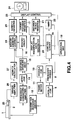
- Fig. 4 represents an overall circuit arrangement of a radio signal detecting system according to a second presently preferred embodiment of the present invention. It should be noted that the same reference numerals shown in Fig. 1 will be employed as those for indicating the same circuit blocks represented in Fig. 4 and other relevant figures, and no further explanations thereof are made in the following descriptions.
- an electronic azimuth sensor 25 such as magnetic sensor is provided on the rotation supporting member 2 of the antenna 1. The electronic azimuth sensor 25 detects the (toward) directions of the antenna 1 which are changed in response to the rotations of this antenna 1, to produce azimuth signals on the basis of the compass north.
- the azimuth signal detected by this electronic azimuth sensor 25 is supplied via a driving/amplifying circuit 26 to an azimuth calculating circuit 27 so as to be calculated as digital azimuth data. Then, the calculated azimuth data is inputted into a memory address control circuit 28, and is used as address data of the memory circuit 16. Further, this azimuth register 29 and displayed on the display unit 24.
- the azimuth data is used as the address data of the memory circuit instead of the previously explained rotation angle data of the antenna 1 employed in the first radio signal detecting system.
- the overall radio signal detecting system is not required to be fixed, the rotation angle of the antenna 1 can be firmly detected even when this second system is slightly swung, or moved.
- the overall first system must be fixed and the rotation angle of the antenna 1 must be judged, or recognized in accordance with the relative position with respect to this previous first system.
- the electronic azimuth sensor 25 may be assembled within the second radio signal detecting system. In this case, it is possible to measure distances about a target with respect to various azimuth positions.
- the distance measuring operation can be performed and the second radio signal detecting system can be made further compact, as compared with the first radio signal detecting system.
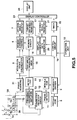
- FIG. 5 there is shown an overall circuit arrangement of a radio signal detecting system according to a third currently preferred embodiment of the present invention.
- this antenna 1A is constructed by arranging a plurality of array antennas 1a, 1b, ... , 1n ("n" being any integers greater than 1).
- n being any integers greater than 1
- slit-shaped elongate opening portions are formed in a waveguide at equi-intervals, and these array antennas are mounted on the respective opening portions of this waveguide along the upright direction, resulting in the antenna 1A.
- both the direction and the distance from the target are measured by electronically scanning the respective array antennas 1a, 1b, ... , 1n.
- the configuration of the entire system can be made simpler and portability of this third system can be further improved.
- Fig. 6 is a detailed display form of the display unit 24 according to any of the first to third radio signal detecting systems.
- the display unit 24 owns a first display screen 24a made of a liquid crystal display (LCD) member. Toroidal-shaped distance scales D, E, F are concentrically displayed on this first display screen 24a. A line “G” is displayed as a heading mark from the center toward the upper position. Further, another line “H” is rotatably displayed in response to the rotation of the antenna 1A.
- the azimuth sensor 25 is additionally employed as the second radio signal detecting system, a north mark "I” is displayed. Then, the target marks J1, J2, J3, ... , Jn measured by these first to third systems are displayed together with these marks.
- an azimuth scale "K” is represented on the peripheral portion of the first display screen 24a by way of printing and a carved seal.
- the distance range "L”, and the interval "M” of the distance scales D, E, F displayed on the first display screen 24a are displayed as a digital value.
- the azimuth "N” of the heading mark G and the azimuth "P” of the line H are displayed as a digital value.
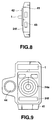
- Figs. 7 and 8 show outer appearances of wrist watches into which the above-described first to third radio signal detecting systems have been embodied.
- a case 41 is fabricated as a wrist watch case.
- a rotary vessel 42 is rotatably fixed on the upper surface of this wrist watch case.
- This rotary vessel 42 corresponds to the above-explained rotation supporting member 2.
- the antenna 1 is mounted on this rotary vessel 42, and the antenna 1 is rotated by manually rotating this rotary vessel 42.
- Reference numeral 43 denotes an operation button arranged on the side surface of this case 41
- reference numeral 44 show an electronic azimuth sensor provided on another side of this case 41. It should be noted that the first display screen 24a to the sixth display screen 24f are arranged on the upper surface of the case 41.
- Fig. 9 represents another example of an outer appearance of the radio signal detecting system.
- the same constructive elements are indicated by the same reference numerals as employed in Fig. 7 and Fig. 8.
- the antenna 1 is fixed on the case 41.
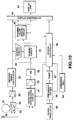
- Fig. 10 schematically shows an overall arrangement of the fourth radio signal detecting system.
- a first antenna 51 formed in a loop shape and a second antenna 52 which is separated from the first antenna 51 and is positioned along the vertical direction.
- the first antenna 51 is vertically mounted on a rotation supporting member 53 which is rotatable in a 360° range.
- the rotation supporting member 53 is rotated, the first antenna 51 is integrally rotated in conjunction with the rotation supporting member 53.
- the rotation angles of the rotation supporting member 53 namely the rotation angles of the first antenna 51 are detected by a rotation angle position detecting sensor 54 constructed as, for instance, a photocoupler.
- the detected rotation angles are derived as rotation angle signals from this sensor 54, and are amplified by a sense amplifier 55.
- the amplified rotation angle signals are supplied to an antenna angle calculating circuit 56 to obtain azimuth angle data.
- the radio signals received by the first antenna 51 and the second antenna 52 are entered into a detecting/synthesizing circuit 57 to be detected and then synthesized with each other, thereby producing field strength data.
- the field strength data is amplified by an amplifying circuit 58, and thereafter converted into a digital field strength value by an A/D-converting circuit 59.
- this field strength data is stored into a memory circuit 61 constructed of an electronic memory such as a RAM.
- the field strength data are stored as digital values at addresses corresponding to the various directional angels under control of a memory address control/read/write control circuit 60.
- the field strength data corresponding to the respective rotation angles are stored into the memory circuit 61.
- the field strength data stored in the memory circuit 61 are supplied via a display control circuit 63 to a display unit 64 such as a liquid crystal display (LCD) for display purposes.
- a display unit 64 such as a liquid crystal display (LCD) for display purposes.
- Reference numeral 62 indicates a maximum value judging circuit.
- the maximum value judging circuit 62 sequentially reads the field strength data out from the memory circuit 61, and makes a decision on the azimuth angle of the highest field strength data among these field strength data, so that this azimuth angle is determined as the direction of the radio signal reflected from the target (not shown in detail). Thus, the determined signal coming direction is displayed on the display unit under control of the display control circuit 63.
- a timer function is provided with the fourth radio signal detecting system.
- a clock signal oscillating circuit 65 is provided to oscillate a clock signal which is used as a time reference pulse signal.
- This reference pulse signal is frequency-divided by a frequency dividing circuit 66, and the frequency-divided pulse signal is furnished to a timer circuit 67 and also via a system control circuit 69 to the display control circuit 63.
- present time is displayed on the display unit 64.
- the system control circuit 69 is employed to control the overall operation of the fourth radio signal detecting system, and an operation unit 68 is manipulated by an operator so as the select data to be displayed on the display unit 64.
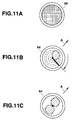
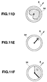
- Fig. 11A to Fig. 11F illustrate display samples of the display unit 64 in the fourth radio signal detecting system.
- the first antenna 51 Before the first antenna 51 is manually, or automatically rotated, no indication is seen on the display unit 64 (see Fig. 11A). Then, when the first antenna 1 is commenced to be rotated, the field strengths of the incoming radio signals which have been processed in accordance with the above-explained manner, are successively displayed on the LCD screen of the display unit 64 as follows: As shown in Fig. 11B, the first antenna 51 is being swept, and a side "A" of the signal incoming direction on the LCD screen is turned ON. Fig.
- FIG. 11C represents such a condition that the first sweeping operation by the first antenna 51 is complete, in which both the side "A" and an opposite side thereof on the LCD screen are turned ON.
- Fig. 11D indicates such a condition that the radio signal information derived from the first antenna 51 is synthesized with the radio signal information derived from the second antenna 52, in which the side "A" of the signal incoming direction is continuously turned ON.
- the maximum value judging circuit 62 may judge the maximum value among the incoming signal levels (field strengths) to determine the radio signal incoming direction.
- the determined signal incoming direction is represented by an arrow as illustrated in Fig. 11E.
- Fig. 11F represents such a condition that the first antenna 51 is being swept during the second sweeping operation, and the arrow indication for the first sweeping operation shown in Fig. 11E is superimposed with this screen display and displayed by a white frame.
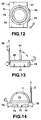
- Fig. 12 to Fig. 14 show various outer appearances of the fourth radio signal detecting system indicated in Fig. 10.
- Reference numeral 71 indicates a wrist watch type case in which the circuit arrangement of the fourth radio signal detecting system is installed.
- An LCD display screen for constituting the display unit 74 is provided on an upper surface of this case 71.
- a toroidal-shaped rotary bezel 73 is arranged around the LCD display screen at the upper surface of the case 71.
- the first antenna 51 having a loop shape is mounted on this rotary bezel 73 in such a manner that this loop antenna 51 can rise up from the rotary bezel 73. Accordingly, the rotary bezel 73 constitutes the rotation supporting member 53 shown in Fig. 10.
- the second antenna 52 is mounted on the side surface of the case 71 in such a way that the second antenna 52 is rotatably fixed thereon and is retractable.
- Reference numeral 74 denotes an operation button
- reference numeral 75 represents a mounting portion of a watch belt (not shown).
- Fig. 15A through Fig. 15D illustrate how to mount/stand the first antenna 51 with respect to the above-explained rotary bezel 73.
- the first antenna 51 is laid on the rotary bezel 73 under the folding condition.
- this first antenna 51 is gradually stood, or raised as illustrated in Fig. 15B and Fig. 15C.
- the first antenna 51 is stood perpendicular to the rotary bezel 73 (see Fig. 15D).
- the rotary bezel 73 is rotated, so that the above-described selection of the signal incoming direction is carried out and is displayed on the LCD display screen 72.
- this detecting system can be made compact and can be readily operated, and furthermore can simply and correctly display the radio signal incoming direction.
- FIG. 16 there is represented an overall arrangement of a radio signal detecting system according to a fifth embodiment of the present invention.
- An electronic azimuth sensor 81 is mounted on the rotation supporting member 53 for rotatably supporting the first antenna 51.
- the electronic azimuth sensor 81 detects earth magnetism with very weak magnetic fields to sense the compass north. Accordingly, the rotation direction of the first antenna 51 is sensed under such a condition that the compass north at the measuring point is used as the reference azimuth.
- a magnetoresistive element may be employed which is positioned within a space defined by, for instance, one electromagnetic coil for operation purposes and the other electromagnetic coil for applying a bias field. These electromagnetic coils are arranged on the X axis and the Y axis perpendicular to the X axis, respectively.
- the azimuth detection signal derived from this electronic azimuth sensor 81 is supplied via a drive circuit and a sense amplifier 82 to an azimuth calculating circuit 83.
- the azimuth calculating circuit 83 converts the azimuth direction analog signal for the first antenna 51 into the corresponding azimuth digital data. Based upon this azimuth digital data, the address of the memory circuit 61 is controlled in order to store the field strength corresponding to the compass north for the first antenna 51.
- reference numeral 84 shows an azimuth register for detecting the maximum field strength from the received field strengths to judge the radio signal incoming direction.
- Reference numeral 85 represents a latch circuit for reading the field strength previously stored in the memory circuit 61
- reference numeral 86 shows a maximum value register write controlling circuit for writing the maximum value read out from the latch circuit 85
- reference numeral 87 represents a register for storing the maximum value of the field strength.
- the maximum field strength value of this register 87 is compared with the maximum field strength value of the latch circuit 85 in a comparator circuit 88, and the comparison result is outputted to the azimuth register 84.
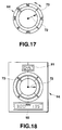
- Fig. 17 illustrates a display screen 72 of a display unit 64 employed in the fifth radio signal detecting system.
- a rotary bezel 73 is arranged outside the LCD display screen 72.
- the azimuth is represented on the rotary bezel 73, and is made coincident with the azimuth of the compass north by rotating this rotary bezel 73.
- an operator can recognize the azimuth of the radio signal incoming direction indicated on the LCD display screen 72.
- Fig. 18 schematically shows another display unit 64 employed in the fifth radio signal detecting system.
- This display unit 64 is provided with a first display section 91 for displaying electronic compass azimuth.
- the first display section 91 indicates the azimuth of 12:00 hour of a clock measured from the compass north.
- a second display section 92 is provided which displays the frequency of the received radio signal and the incoming direction of this received radio signal by the angle measured from the compass north.
- the radio signal incoming direction is displayed by either the absolute direction, or the digital value from 0° to 360° , this azimuth of the radio signal incoming direction can be confirmed. While the first antenna 51 is rotated, the radio signal incoming direction can be correctly displayed irrelevant to the direction and the attitude of the fifth radio signal detecting system, resulting in improvements of operabilities thereof.
Abstract
Description
- The present invention generally relates to a radio signal detecting system capable of detecting a radio signal reflected from a target. More specifically, the present invention is directed to a compact radio signal detecting system capable of measuring a distance from the target and a direction of the target, and also capable of detecting azimuth of an incoming radio signal transmitted from other radio signal transmitter.
- Radar systems have been widely utilized in air crafts and ships in order to navigate these vehicles and to confirm present positions of the vehicles with respect to a target, and also utilized in meteorological observations. Typically, in a radar system employed in one ship, an electromagnetic wave in a pulse form such as a microwave pulse signal, is transmitted from an antenna at a speed of 300,000 km/sec., and this pulse signal impinges other ships and a land. Then, pulse signals are reflected from these objects and processed to measure distances between this ship and other ships. These measured distances are displayed on a CRT display screen.
- This type of conventional marine radar system is arranged by a large-scale transmitter apparatus with employment of a magnetron and the like, a bulky rotary slot antenna having a length of 1 to 3 m and an antenna unit, a display apparatus equipped with an after-image type large CRT screen, and a motor unit for rotating the slot antenna. Accordingly, this marine radar system can own various merits, e.g., high power, high precision, and hard operation conditions. However, there are drawbacks such as bulky system and high power consumption.
- On the other hand, in commercial ships such as fishing boats and container carrier ships, and salvage stations, azimuth detecting systems are utilized to correctly detect azimuth of a signal radiation source by measuring azimuth of an incoming radio signal having a specific frequency. In the azimuth detecting system, the incoming radio signals are received by the first loop-shaped antenna and the second vertically-arranged antenna. The first loop antenna is rotated to receive the radio signals at every preselected rotation angle, and field strengths of these received radio signals are measured. Then, the direction of one radio signal having the highest field strength is detected as the direction of the incoming radio signal reflected from the target. Since this first loop antenna inherently owns such an antenna characteristic that the field strengths become high when the first loop antenna is located at 90° and 270° with respect to the direction of the incoming radio signal, a decision is made which incoming signal angle corresponds to the incoming direction of the radio signal based upon directivity of the second antenna. In other words, the radio signal received by the first loop antenna is synthesized with the radio signal received by the second antenna, thereby determing the incoming direction of the radio signal. Thereafter, the synthesized signal is amplified, and the field strengths of the synthesized signal with regard to the rotation angles of the first loop antenna are displayed on a CRT display screen as a circular graphic representation.
- However, the above-described conventional azimuth detecting systems own similar problems to those of the conventional radar systems. That is, very high technology is required to operate such conventional azimuth detecting systems, so that only well skilled operators can handle these azimuth detecting systems.
- The present invention has been made to solve the above-described conventional problems, and therefore, has an object to provide a radio signal detecting system made compact and in light weight.
- Another object of the present invention is to provide a portable radio signal detecting system operable by any operators who are not required as well skilled operators, and suitable to be outdoor use.
- To achieve the above-described objects, a radio signal detecting system according to an aspect of the present invention is characterized by comprising:
a rotatable antenna;
distance measuring means for transmitting a radio signal every time the antenna is rotated by a preselected rotation angle, and for receiving another radio signal reflected from a target to be measured to process the reflected radio signal, thereby producing distance data;
memory means for storing the distance data produced by the distance measuring means in correspondence with the rotation angle of the antenna; and
display means for displaying the distance data read out from the memory means. - Also, a radio signal detecting system according to another aspect of the present invention is characterized by comprising:
a wrist-watch-shaped case;
an antenna rotatably mounted on the wrist-watch-shaped case;
timer circuit means provided within said case, for producing present time information;
time display means for displaying the present time information produced by said time circuit means;
distance measuring means for transmitting a radio signal every time the antenna is rotated by a preselected rotation angle, and for receiving another radio signal reflected from a target to be measured to process the reflected radio signal, thereby producing distance data;
memory means for storing the distance data produced by the distance measuring means in correspondence with the rotation angle of the antenna; and
display means for displaying the distance data read out from the memory means. - For a better understanding of the present invention, reference is made of the detailed description to be read in conjunction with the accompanying drawings, in which:
- Fig 1 is a schematic block diagram for representing an overall circuit arrangement of a radio signal detecting system according to a first preferred embodiment of the present invention;
- Fig. 2 shows a waveform of a pulse signal transmitted/received in the first radio signal detecting system of Fig. 1;
- Fig. 3 schematically illustrates a display sample of the first radio signal detecting system as a front view;
- Fig. 4 is a schematic block diagram for showing an overall circuit arrangement of a radio signal detecting system according to a second preferred embodiment of the present invention;
- Fig. 5 is a schematic block diagram for indicating an overall circuit arrangement of a radio signal detecting system according to a third preferred embodiment of the present invention;
- Fig. 6 schematically illustrates a display sample of a display unit employed in the first to third radio signal detecting systems;
- Fig. 7 is a front view for showing an outer appearance of the first to third radio signal detecting systems;
- Fig. 8 is a side view for showing the first to third radio signal detecting systems;
- Fig. 9 is a front view for indicating another outer appearance of the first to third radio signal detecting systems;
- Fig. 10 is a schematic block diagram for indicating an overall circuit arrangement of a radio signal detecting system according to a fourth preferred embodiment of the present invention;
- Figs. 11A to 11F schematically represent display samples of the display unit employed in the fourth radio signal detecting system;
- Fig. 12 is a plan view for indicating an outer configuration of the fourth radio signal detecting system;
- Fig. 13 is a side view for showing the outer configuration of the fourth radio signal detecting system;
- Fig. 14 is a side view for representing another outer configuration of the fourth radio signal detecting system;
- Figs. 15A to 15D are perspective views for indicating various operations of a first antenna;
- Fig. 16 is a schematic block diagram for showing an overall circuit arrangement of a radio signal detecting system according to a fifth preferred embodiment of the present invention;
- Fig. 17 is a front view for indicating a display sample of the fifth radio signal detecting system; and
- Fig. 18 is a front view of representing another display sample of the fifth radio signal detecting system.
- Referring now to Fig. 1 to Fig. 3, a description will be made of a radio signal detecting system assembled in an electronic wrist watch, according to a first presently preferred embodiment of the present invention.
- In Fig. 1, there is shown an overall circuit arrangement of the first radio signal detecting system. In this first radio signal detecting system, a
compact antenna 1 is mounted on arotation supporting member 2, so that theantenna 1 is integrally rotatable in conjunction with the rotation of therotation supporting member 2. The rotating operation of thisrotation supporting member 2 is manually performed, and detected by a rotationangle detecting sensor 3. As this rotationangle detecting sensor 3, it may be so arranged that light/dark marks made from slits or black/white marks are formed on the same circular of therotation supporting member 2, and these light/dark marks are detected by way of a photocoupler constructed of a light emitting diode (LED) and a phototransistor, whereby the rotation angles of therotation supporting member 2 are detected in the form of pulse number. - A clock pulse indicative of the rotation angle of the
antenna 1, which is outputted from this rotationangle detecting sensor 3, is entered via a driving/amplifyingcircuit 4 into an antennaangle calculating circuit 5. The number of clock pulses is added to each other, and thus, is outputted as angle data about theantenna 1 from this antennaangle calculating circuit 5. The derived angle data is stored via a memoryaddress control circuit 6 into anantenna angle register 7, and then displayed on adisplay unit 24. - An
oscillator circuit 8, a frequency dividingcircuit 9, acontrol circuit 19, and atimer circuit 22 will constitute an electronic watch circuit. That is, theoscillator circuit 8 oscillates a reference frequency pulse functioning as a reference timing signal. Thefrequency dividing circuit 9 frequency-divides this reference frequency pulse to obtain a frequency-divided pulse. The frequency-divided pulse is supplied via thecontrol circuit 19 to thetimer circuit 22 for performing the time counting operation. Accordingly, present time is displayed on thedisplay unit 24 under control by thedisplay control circuit 23. - In this first embodiment, the reference frequency pulse which has been frequency-divided by the
frequency dividing circuit 9, is also outputted to a modulatingcircuit 10. This frequency-divided pulse is modulated by a high (radio) frequency signal in the modulatingcircuit 10. The modulated radio frequency signal is furnished to atransmitter circuit 11. Thetransmitter circuit 11 supplies a transmission pulse signal to a transmitter/receiver switching circuit 12, and also supplies a signal synchronized with this transmission pulse signal to adistance measuring circuit 15. - The transmitter/
receiver switching circuit 12 switches radiation of the radio signal (electromagnetic wave) carried out by the above-explained transmission pulse signal through theantenna 1, and receptions of the radio signal reflected from a target. The reflected radio signals received by this transmitter/receiver switching circuit 12 are amplified by a frequency converting/amplifyingcircuit 13, and thereafter the amplified radio signals are detected by a detectingcircuit 14, so that the detected radio signals are furnished to thedistance measuring circuit 15. Thedistance measuring circuit 15 measures a time period since the signal synchronized with the above-explained transmission pulse signal is supplied from thetransmitter circuit 11 until the reflected radio signals which have been detected by the detectingcircuit 14 are inputted. Then, thedistance measuring circuit 15 outputs distance data based on this measured time period. This time period measuring operation is carried out by utilizing the clock pulse derived from thefrequency dividing circuit 9. This distance data corresponds to digital data indicative of a distance between a target and this radio signal detecting system. This distance data is supplied to amemory circuit 16 constructed of such an electronic memory as a RAM (random access memory). - The
memory circuit 16 contains a large number of memory regions for storing the distance data about the target, and the respective memory regions are addressed by theaddress control circuit 6 to which the angle data derived from the antennaangle calculating circuit 5 are supplied as the address data. - For instance, since the distance data in correspondence with every 10 ° (degrees) with respect to one rotation angle (360° ) of the
antenna 1 may be stored in thememory circuit 15, thismemory circuit 15 is arranged by the memory regions capable of storing 36 pieces of distance data. These distance data stored in the memory circuit, are read out therefrom and stored via thecontrol circuit 19 and the memoryaddress control circuit 6 into atarget distance register 17 by operating a distance display button (not shown) provided on anoperation unit 18, and further are displayed on thedisplay unit 24. This distance data display is continued until this distance display button is subsequently manipulated. A display-magnification-data output circuit 20 controls the display magnification of the distance data to be displayed. Precisely speaking, when a magnification selecting key (not shown either) of theoperation unit 18 is operated to designate desired display magnification, the magnification data designated via thecontrol circuit 20 by the display-magnification-data output circuit 20 is supplied to thetarget distance register 17 and adistance scale register 21, so that the distance data is displayed in the designated magnification, and also a scale adjusted in accordance with the designated magnification is displayed. - In the first radio signal detecting system shown in Fig. 1, a transmission pulse is transmitted from the
antenna 1 and a reception pulse is received from thisantenna 1 as represented in Fig. 2. The transmission pulse is transmitted with a time width "L" in a time period "T1", and the reception pulse (reflection pulses "A" and "B") is received between the successive transmission pulses within a time period T2 (see Fig. 2). That is, for example, when a first transmission pulse is transmitted with a time width "L", theantenna 1 is switched from the transmission mode to the reception mode during another time period "T2". During this time period "T2", the electromagnetic waves reflected from the target (not shown in detail) are received via theantenna 1 by the first radio signal detecting system. When, for instance, two reflection pulse signals "A" and "B" are received under such a condition that theantenna 1 has been rotated by an angle "O" during this time interval T2, such a representation that two targets A' and B' are present is made on thedisplay unit 24, as illustrated in Fig. 3. - In the above-explained first radio signal detecting system, microwaves having very low signal levels, and FM signals of quasi-microwave band waves such as UHF waves and VHF waves may be utilized as the transmission pulse from the
antenna 1. As a consequence, although the distance measuring range of this first radio signal detecting system would be narrowed to some extent because of using such high frequency signals, there are various merits that the circuit arrangement for transmitting/receiving the pulse signals could be made compact, and furthermore this transmitting/receiving circuit arrangement could be manufactured as an integrated circuit in combination with thecontrol circuit 19, thetimer circuit 22, and the antennaangle calculating circuit 5. - Further, when such a liquid crystal display (LCD) operable under very small currents on the order of microampere is employed as the
display unit 24, power consumption of this first radio signal detecting system can be reduced. Accordingly, this LCD display unit may be operated by small-sized batteries such as dry cells and button type cells, which are originally used to operate other circuit arrangements. As a consequence, since no longer commercial power source with high capacity is required to operate the first radio signal detecting system, this detecting system can be furthermore made compact. - Under such circumstances, the first radio signal detecting system may be manufactured in the form of compact electronic appliances, e.g., a wrist watch, a desk top calculator, and an electronic notebook. Moreover, this system may be realized as portable outdoor gears.
- Fig. 4 represents an overall circuit arrangement of a radio signal detecting system according to a second presently preferred embodiment of the present invention. It should be noted that the same reference numerals shown in Fig. 1 will be employed as those for indicating the same circuit blocks represented in Fig. 4 and other relevant figures, and no further explanations thereof are made in the following descriptions. As a feature of this second radio signal detecting system, an
electronic azimuth sensor 25 such as magnetic sensor is provided on therotation supporting member 2 of theantenna 1. Theelectronic azimuth sensor 25 detects the (toward) directions of theantenna 1 which are changed in response to the rotations of thisantenna 1, to produce azimuth signals on the basis of the compass north. The azimuth signal detected by thiselectronic azimuth sensor 25 is supplied via a driving/amplifyingcircuit 26 to anazimuth calculating circuit 27 so as to be calculated as digital azimuth data. Then, the calculated azimuth data is inputted into a memoryaddress control circuit 28, and is used as address data of thememory circuit 16. Further, thisazimuth register 29 and displayed on thedisplay unit 24. - In the above-explained second radio signal detecting system, the azimuth data is used as the address data of the memory circuit instead of the previously explained rotation angle data of the
antenna 1 employed in the first radio signal detecting system. As a result, since the overall radio signal detecting system is not required to be fixed, the rotation angle of theantenna 1 can be firmly detected even when this second system is slightly swung, or moved. To the contrary, the overall first system must be fixed and the rotation angle of theantenna 1 must be judged, or recognized in accordance with the relative position with respect to this previous first system. - Alternatively, according to the modifications of the second embodiment, the
electronic azimuth sensor 25 may be assembled within the second radio signal detecting system. In this case, it is possible to measure distances about a target with respect to various azimuth positions. - Furthermore, even when the mechanism for rotating the
antenna 1 is not employed, the distance measuring operation can be performed and the second radio signal detecting system can be made further compact, as compared with the first radio signal detecting system. - As previously described, in accordance with the second embodiment, since both the distance and the azimuth of the target in correspondence with the absolute azimuth are displayed, high-precision target measurement and display can be realized with easy operations.
- In Fig. 5, there is shown an overall circuit arrangement of a radio signal detecting system according to a third currently preferred embodiment of the present invention.
- As apparent from this figure 5, only a structure of an
antenna 1A of this third radio signal detecting system is different from that of theantenna 1 employed in the first radio signal detecting system indicated in Fig. 1. That is, thisantenna 1A is constructed by arranging a plurality ofarray antennas array antennas antenna 1A. Then, both the direction and the distance from the target are measured by electronically scanning therespective array antennas antenna 1A itself is not required to be rotated, the configuration of the entire system can be made simpler and portability of this third system can be further improved. - Fig. 6 is a detailed display form of the
display unit 24 according to any of the first to third radio signal detecting systems. Thedisplay unit 24 owns afirst display screen 24a made of a liquid crystal display (LCD) member. Toroidal-shaped distance scales D, E, F are concentrically displayed on thisfirst display screen 24a. A line "G" is displayed as a heading mark from the center toward the upper position. Further, another line "H" is rotatably displayed in response to the rotation of theantenna 1A. When theazimuth sensor 25 is additionally employed as the second radio signal detecting system, a north mark "I" is displayed. Then, the target marks J1, J2, J3, ... , Jn measured by these first to third systems are displayed together with these marks. - It should be understood that an azimuth scale "K" is represented on the peripheral portion of the
first display screen 24a by way of printing and a carved seal. On asecond display screen 24b of theLCD display unit 24, the distance range "L", and the interval "M" of the distance scales D, E, F displayed on thefirst display screen 24a are displayed as a digital value. On athird display screen 24c of thisLCD display unit 24, the azimuth "N" of the heading mark G and the azimuth "P" of the line H are displayed as a digital value. On "Q" and "R" of afourth display screen 24d of thisLCD display unit 24, there are represented a digital value indicative of a distance up to the distance scale "D" positioned outside thedisplay screen 24a, and a digital value indicative of a distance up to the distance scale "E". Furthermore, present month/day/time are displayed in the digital forms on afifth display screen 24e of theLCD display unit 25. - Figs. 7 and 8 show outer appearances of wrist watches into which the above-described first to third radio signal detecting systems have been embodied.
- A
case 41 is fabricated as a wrist watch case. Arotary vessel 42 is rotatably fixed on the upper surface of this wrist watch case. Thisrotary vessel 42 corresponds to the above-explainedrotation supporting member 2. Thus, theantenna 1 is mounted on thisrotary vessel 42, and theantenna 1 is rotated by manually rotating thisrotary vessel 42. - As previously explained, in such a system configuration where the
antenna 1 is manually rotated, no electric motor is required and this power consumption can be lowered and also the system can be made compact.Reference numeral 43 denotes an operation button arranged on the side surface of thiscase 41, andreference numeral 44 show an electronic azimuth sensor provided on another side of thiscase 41. It should be noted that thefirst display screen 24a to thesixth display screen 24f are arranged on the upper surface of thecase 41. - Fig. 9 represents another example of an outer appearance of the radio signal detecting system. The same constructive elements are indicated by the same reference numerals as employed in Fig. 7 and Fig. 8. In this outer appearance example, the
antenna 1 is fixed on thecase 41. - Referring now to Fig. 10 to Fig. 15, a radio signal detecting system according to a fourth embodiment of the present invention will be explained.
- First, Fig. 10 schematically shows an overall arrangement of the fourth radio signal detecting system. In this fourth radio signal detecting system, there are provided a
first antenna 51 formed in a loop shape and asecond antenna 52 which is separated from thefirst antenna 51 and is positioned along the vertical direction. Thefirst antenna 51 is vertically mounted on arotation supporting member 53 which is rotatable in a 360° range. When thisrotation supporting member 53 is rotated, thefirst antenna 51 is integrally rotated in conjunction with therotation supporting member 53. The rotation angles of therotation supporting member 53, namely the rotation angles of thefirst antenna 51 are detected by a rotation angleposition detecting sensor 54 constructed as, for instance, a photocoupler. The detected rotation angles are derived as rotation angle signals from thissensor 54, and are amplified by asense amplifier 55. The amplified rotation angle signals are supplied to an antennaangle calculating circuit 56 to obtain azimuth angle data. - On the other hand, the radio signals received by the
first antenna 51 and thesecond antenna 52 are entered into a detecting/synthesizingcircuit 57 to be detected and then synthesized with each other, thereby producing field strength data. The field strength data is amplified by an amplifyingcircuit 58, and thereafter converted into a digital field strength value by an A/D-convertingcircuit 59. Thus, this field strength data is stored into amemory circuit 61 constructed of an electronic memory such as a RAM. In thememory circuit 61, the field strength data are stored as digital values at addresses corresponding to the various directional angels under control of a memory address control/read/write control circuit 60. In this manner, after thefirst antenna 51 has been rotated for every preselected angle by either the manual scanning operation, or the automatic scanning operation over 0° to 360° fields, the field strength data corresponding to the respective rotation angles are stored into thememory circuit 61. Then, the field strength data stored in thememory circuit 61 are supplied via adisplay control circuit 63 to adisplay unit 64 such as a liquid crystal display (LCD) for display purposes. In this case, when the rotation angle of thefirst antenna 51 is supplied from the antennaangle calculating circuit 6 into thedisplay control circuit 63, this azimuth angle is displayed on thedisplay unit 64 under control of thedisplay control circuit 63. -
Reference numeral 62 indicates a maximum value judging circuit. The maximumvalue judging circuit 62 sequentially reads the field strength data out from thememory circuit 61, and makes a decision on the azimuth angle of the highest field strength data among these field strength data, so that this azimuth angle is determined as the direction of the radio signal reflected from the target (not shown in detail). Thus, the determined signal coming direction is displayed on the display unit under control of thedisplay control circuit 63. - In addition to the above-described azimuth measuring function, a timer function is provided with the fourth radio signal detecting system. Referring back to the overall circuit arrangement shown in Fig. 10, a clock
signal oscillating circuit 65 is provided to oscillate a clock signal which is used as a time reference pulse signal. This reference pulse signal is frequency-divided by afrequency dividing circuit 66, and the frequency-divided pulse signal is furnished to atimer circuit 67 and also via asystem control circuit 69 to thedisplay control circuit 63. As a result, present time is displayed on thedisplay unit 64. It should be noted that thesystem control circuit 69 is employed to control the overall operation of the fourth radio signal detecting system, and anoperation unit 68 is manipulated by an operator so as the select data to be displayed on thedisplay unit 64. - Fig. 11A to Fig. 11F illustrate display samples of the
display unit 64 in the fourth radio signal detecting system. Before thefirst antenna 51 is manually, or automatically rotated, no indication is seen on the display unit 64 (see Fig. 11A). Then, when thefirst antenna 1 is commenced to be rotated, the field strengths of the incoming radio signals which have been processed in accordance with the above-explained manner, are successively displayed on the LCD screen of thedisplay unit 64 as follows: As shown in Fig. 11B, thefirst antenna 51 is being swept, and a side "A" of the signal incoming direction on the LCD screen is turned ON. Fig. 11C represents such a condition that the first sweeping operation by thefirst antenna 51 is complete, in which both the side "A" and an opposite side thereof on the LCD screen are turned ON. Fig. 11D indicates such a condition that the radio signal information derived from thefirst antenna 51 is synthesized with the radio signal information derived from thesecond antenna 52, in which the side "A" of the signal incoming direction is continuously turned ON. Thereafter, the maximumvalue judging circuit 62 may judge the maximum value among the incoming signal levels (field strengths) to determine the radio signal incoming direction. As a result, the determined signal incoming direction is represented by an arrow as illustrated in Fig. 11E. Fig. 11F represents such a condition that thefirst antenna 51 is being swept during the second sweeping operation, and the arrow indication for the first sweeping operation shown in Fig. 11E is superimposed with this screen display and displayed by a white frame. - Fig. 12 to Fig. 14 show various outer appearances of the fourth radio signal detecting system indicated in Fig. 10.
Reference numeral 71 indicates a wrist watch type case in which the circuit arrangement of the fourth radio signal detecting system is installed. An LCD display screen for constituting thedisplay unit 74 is provided on an upper surface of thiscase 71. A toroidal-shapedrotary bezel 73 is arranged around the LCD display screen at the upper surface of thecase 71. Thefirst antenna 51 having a loop shape is mounted on thisrotary bezel 73 in such a manner that thisloop antenna 51 can rise up from therotary bezel 73. Accordingly, therotary bezel 73 constitutes therotation supporting member 53 shown in Fig. 10. On the other hand, thesecond antenna 52 is mounted on the side surface of thecase 71 in such a way that thesecond antenna 52 is rotatably fixed thereon and is retractable. As previously described in detail, since both thefirst antenna 51 and thesecond antenna 52 are collapsable, no projecting portion is made in this wrist watch type case, so that this case may be easily handled when the fourth radio signal detecting system is not under operation.Reference numeral 74 denotes an operation button, andreference numeral 75 represents a mounting portion of a watch belt (not shown). - Fig. 15A through Fig. 15D illustrate how to mount/stand the
first antenna 51 with respect to the above-explainedrotary bezel 73. As shown in Fig. 15A, thefirst antenna 51 is laid on therotary bezel 73 under the folding condition. When thefirst antenna 51 is manually pulled up, thisfirst antenna 51 is gradually stood, or raised as illustrated in Fig. 15B and Fig. 15C. Finally, thefirst antenna 51 is stood perpendicular to the rotary bezel 73 (see Fig. 15D). Under this standing condition of Fig. 15D, therotary bezel 73 is rotated, so that the above-described selection of the signal incoming direction is carried out and is displayed on theLCD display screen 72. - As previously explained, in accordance with the fourth radio signal detecting system, this detecting system can be made compact and can be readily operated, and furthermore can simply and correctly display the radio signal incoming direction.
- In Fig. 16, there is represented an overall arrangement of a radio signal detecting system according to a fifth embodiment of the present invention. It should be noted that like reference numerals shown in the fourth embodiment refer to like circuit portions of this fifth embodiment, and therefore no further explanations thereof are made in the below-mentioned description. An
electronic azimuth sensor 81 is mounted on therotation supporting member 53 for rotatably supporting thefirst antenna 51. Theelectronic azimuth sensor 81 detects earth magnetism with very weak magnetic fields to sense the compass north. Accordingly, the rotation direction of thefirst antenna 51 is sensed under such a condition that the compass north at the measuring point is used as the reference azimuth. As theelectronic azimuth sensor 81, a magnetoresistive element may be employed which is positioned within a space defined by, for instance, one electromagnetic coil for operation purposes and the other electromagnetic coil for applying a bias field. These electromagnetic coils are arranged on the X axis and the Y axis perpendicular to the X axis, respectively. - The azimuth detection signal derived from this
electronic azimuth sensor 81 is supplied via a drive circuit and asense amplifier 82 to anazimuth calculating circuit 83. Theazimuth calculating circuit 83 converts the azimuth direction analog signal for thefirst antenna 51 into the corresponding azimuth digital data. Based upon this azimuth digital data, the address of thememory circuit 61 is controlled in order to store the field strength corresponding to the compass north for thefirst antenna 51. In the fifth radio signal detecting system of Fig. 16,reference numeral 84 shows an azimuth register for detecting the maximum field strength from the received field strengths to judge the radio signal incoming direction.Reference numeral 85 represents a latch circuit for reading the field strength previously stored in thememory circuit 61,reference numeral 86 shows a maximum value register write controlling circuit for writing the maximum value read out from thelatch circuit 85, andreference numeral 87 represents a register for storing the maximum value of the field strength. The maximum field strength value of thisregister 87 is compared with the maximum field strength value of thelatch circuit 85 in acomparator circuit 88, and the comparison result is outputted to theazimuth register 84. - Fig. 17 illustrates a
display screen 72 of adisplay unit 64 employed in the fifth radio signal detecting system. As represented in Fig. 17, arotary bezel 73 is arranged outside theLCD display screen 72. The azimuth is represented on therotary bezel 73, and is made coincident with the azimuth of the compass north by rotating thisrotary bezel 73. As a result, an operator can recognize the azimuth of the radio signal incoming direction indicated on theLCD display screen 72. - Fig. 18 schematically shows another
display unit 64 employed in the fifth radio signal detecting system. Thisdisplay unit 64 is provided with afirst display section 91 for displaying electronic compass azimuth. Thefirst display section 91 indicates the azimuth of 12:00 hour of a clock measured from the compass north. Furthermore, asecond display section 92 is provided which displays the frequency of the received radio signal and the incoming direction of this received radio signal by the angle measured from the compass north. - In accordance with the fifth radio signal detecting system, since the radio signal incoming direction is displayed by either the absolute direction, or the digital value from 0° to 360° , this azimuth of the radio signal incoming direction can be confirmed. While the
first antenna 51 is rotated, the radio signal incoming direction can be correctly displayed irrelevant to the direction and the attitude of the fifth radio signal detecting system, resulting in improvements of operabilities thereof.
Claims (10)
- A radio signal detecting system including: an appliance case (41, 71); an antenna (1, 1A, 51, 52) rotatably mounted on the appliance case; receiver means (13, 14, 57, 58, 59) for receiving a radio signal every time the antenna is rotated by a predetermined rotation angle; and display means (24, 64) for displaying the radio signal received by the receiver means, characterized by comprising:
digital converting circuit means (15, 59) for converting said radio signal received by said receiver means into digital data;
memory means (16, 61) for storing therein said digital data converted by said digital converting circuit means in correspondence with the rotation angle of said antenna; and
display control means (17, 23, 63) for reading out said digital data stored in said memory means to display said read digital data on said display means (24, 64). - A radio signal detecting system as claimed in claim 1, further comprising:
radiation means (10, 11) for radiating a radio signal via said antenna, said radio signal received by said receiver means being a reflection signal reflected from a target to which said radiated radio signal impinges. - A radio signal detecting system as claimed in claim 1, further comprising:
radiation means (10, 11) for radiating a radio signal via said antenna; wherein
said receiver means (13, 14, 57, 58, 59) receives a reflection signal reflected from a target to which said radiated radio signal impinges; and
said digital converting circuit means (15, 59) calculates distance data measured between said radio signal detecting system and said target based upon time difference data defined by that since the radio signal is radiated, and until the reflection signal is received, thereby outputting the distance data as said digital data. - A radio signal detecting system as claimed in claim 1 wherein said digital data converted by said digital converting circuit means is digital data indicative of a field strength of the reflection signal received by said receiver means (13, 14, 57, 58, 59).
- A radio signal detecting system as claimed in claim 1 wherein said antenna is manually rotatable by an operator.
- A radio signal detecting system as claimed in claim 1 wherein said antenna is arranged by an array antenna such that a plurality of slit-shaped elongate openings are formed in a waveguide at an equidistant interval.
- A radio signal detecting system as claimed in claim 1, further comprising:
radiation means (10, 11) for radiating a radio signal via said antenna; wherein
said receiver means (13, 14, 57, 58, 59) receives a reflection signal reflected from a target to which said radiated radio signal impinges;
said digital converting circuit means (15, 59) calculates distance data measured between said radio signal detecting system and said target based upon time difference data defined by that since the radio signal is radiated, and until the reflection signal is received, thereby outputting the distance data as said digital data; and
said memory means for storing said distance data in correspondence with the rotation angle of said antenna. - A radio signal detecting system as claimed in claim 7, further comprising:
angle detecting means (3, 5, 54, 56) for detecting the rotation angle of said antenna, said memory means being operated based on the detected rotation angle from said angle detecting means. - A radio signal detecting system as claimed in claim 1, further comprising:
azimuth measuring means (25, 27, 31, 33) for measuring azimuth; and
azimuth displaying means for displaying the azimuth measured by said azimuth measuring means. - A radio signal detecting system as claimed in claim 1 wherein said appliance case is a wrist-watch-shaped case mounted on a wrist arm of an operator.
Applications Claiming Priority (6)
| Application Number | Priority Date | Filing Date | Title |
|---|---|---|---|
| JP187559/93 | 1993-06-30 | ||
| JP187557/93 | 1993-06-30 | ||
| JP5187559A JPH0720232A (en) | 1993-06-30 | 1993-06-30 | Radar apparatus |
| JP18755993 | 1993-06-30 | ||
| JP18755793 | 1993-06-30 | ||
| JP18755793A JP3404806B2 (en) | 1993-06-30 | 1993-06-30 | Signal strength display |
Publications (3)
| Publication Number | Publication Date |
|---|---|
| EP0632287A2 true EP0632287A2 (en) | 1995-01-04 |
| EP0632287A3 EP0632287A3 (en) | 1996-10-09 |
| EP0632287B1 EP0632287B1 (en) | 2003-12-17 |
Family
ID=26504436
Family Applications (1)
| Application Number | Title | Priority Date | Filing Date |
|---|---|---|---|
| EP94109912A Expired - Lifetime EP0632287B1 (en) | 1993-06-30 | 1994-06-27 | Portable radio signal detecting system |
Country Status (5)
| Country | Link |
|---|---|
| US (1) | US5534872A (en) |
| EP (1) | EP0632287B1 (en) |
| CN (1) | CN1059036C (en) |
| DE (1) | DE69433419T2 (en) |
| HK (1) | HK1013441A1 (en) |
Cited By (1)
| Publication number | Priority date | Publication date | Assignee | Title |
|---|---|---|---|---|
| CN102711151A (en) * | 2012-05-02 | 2012-10-03 | 京信通信系统(中国)有限公司 | Intelligent digital radio-frequency repeater and control method thereof |
Families Citing this family (11)
| Publication number | Priority date | Publication date | Assignee | Title |
|---|---|---|---|---|
| JPH10126135A (en) * | 1994-09-09 | 1998-05-15 | Software Sekkei:Kk | Direction measurement method and direction measurement device for beam antenna and direction controller for antenna |
| US6041242A (en) * | 1996-06-21 | 2000-03-21 | Coulthard; Steve M. | Portable emergency response communications system and method |
| US6677889B2 (en) * | 2002-01-22 | 2004-01-13 | Raytheon Company | Auto-docking system |
| US6707414B2 (en) * | 2002-01-22 | 2004-03-16 | Raytheon Company | Docking information system for boats |
| EP1369954A3 (en) * | 2002-06-05 | 2004-10-20 | Fujitsu Limited | Adaptive antenna unit for mobile terminal |
| EP1612986A4 (en) * | 2003-09-04 | 2006-02-22 | Doshisha | Radio communication system |
| US7406295B1 (en) * | 2003-09-10 | 2008-07-29 | Sprint Spectrum L.P. | Method for dynamically directing a wireless repeater |
| US7480486B1 (en) | 2003-09-10 | 2009-01-20 | Sprint Spectrum L.P. | Wireless repeater and method for managing air interface communications |
| EP1983299B1 (en) * | 2007-04-16 | 2010-05-26 | MOBA - Mobile Automation AG | Apparatus and method for determining an elevation of working tools based on a laser system |
| GB2459479B8 (en) * | 2008-04-23 | 2012-08-08 | Bigger Than The Wheel Ltd | Short range RF monitoring system |
| TWI675209B (en) * | 2018-11-15 | 2019-10-21 | 銓鼎塑膠股份有限公司 | A system for measuring and adjusting an antenna radiation pattern |
Citations (5)
| Publication number | Priority date | Publication date | Assignee | Title |
|---|---|---|---|---|
| JPS5544970A (en) * | 1978-09-27 | 1980-03-29 | Toshiba Corp | Radar display device |
| US4364048A (en) * | 1980-08-13 | 1982-12-14 | The United States Of America As Represented By The Secretary Of The Navy | Interleaved sweep radar display for improved target detection |
| JPS6148283A (en) * | 1984-08-14 | 1986-03-08 | Furuno Electric Co Ltd | Video display device |
| US4588992A (en) * | 1982-11-01 | 1986-05-13 | Clark William E | Radar tracking system and display |
| US5077559A (en) * | 1990-02-01 | 1991-12-31 | Matsushita Electric Industrial Co., Ltd. | Radar apparatus |
Family Cites Families (4)
| Publication number | Priority date | Publication date | Assignee | Title |
|---|---|---|---|---|
| US3721950A (en) * | 1969-08-13 | 1973-03-20 | Sanders Associates Inc | Responsive navigation beacon |
| JPS58148526A (en) * | 1982-02-26 | 1983-09-03 | Mitsubishi Electric Corp | Device for rescue signal |
| JP2509317B2 (en) * | 1987-03-03 | 1996-06-19 | コクラン コンサルティング インコーポレイティド | Diving parameter display device |
| SE465391B (en) * | 1990-07-24 | 1991-09-02 | Staffan Gunnarsson | VEHICLE DEVICE MAINTAINS POSITIONING BY AUTOMATIC FUELING |
-
1994
- 1994-06-22 US US08/263,474 patent/US5534872A/en not_active Expired - Lifetime
- 1994-06-27 EP EP94109912A patent/EP0632287B1/en not_active Expired - Lifetime
- 1994-06-27 DE DE69433419T patent/DE69433419T2/en not_active Expired - Lifetime
- 1994-06-30 CN CN94107808A patent/CN1059036C/en not_active Expired - Fee Related
-
1998
- 1998-12-22 HK HK98114705A patent/HK1013441A1/en not_active IP Right Cessation
Patent Citations (5)
| Publication number | Priority date | Publication date | Assignee | Title |
|---|---|---|---|---|
| JPS5544970A (en) * | 1978-09-27 | 1980-03-29 | Toshiba Corp | Radar display device |
| US4364048A (en) * | 1980-08-13 | 1982-12-14 | The United States Of America As Represented By The Secretary Of The Navy | Interleaved sweep radar display for improved target detection |
| US4588992A (en) * | 1982-11-01 | 1986-05-13 | Clark William E | Radar tracking system and display |
| JPS6148283A (en) * | 1984-08-14 | 1986-03-08 | Furuno Electric Co Ltd | Video display device |
| US5077559A (en) * | 1990-02-01 | 1991-12-31 | Matsushita Electric Industrial Co., Ltd. | Radar apparatus |
Non-Patent Citations (2)
| Title |
|---|
| PATENT ABSTRACTS OF JAPAN vol. 004, no. 082 (P-015), 13 June 1980 & JP-A-55 044970 (TOSHIBA CORP), 29 March 1980, * |
| PATENT ABSTRACTS OF JAPAN vol. 010, no. 205 (E-420), 17 July 1986 & JP-A-61 048283 (FURUNO ELECTRIC CO LTD), 8 March 1986, * |
Cited By (1)
| Publication number | Priority date | Publication date | Assignee | Title |
|---|---|---|---|---|
| CN102711151A (en) * | 2012-05-02 | 2012-10-03 | 京信通信系统(中国)有限公司 | Intelligent digital radio-frequency repeater and control method thereof |
Also Published As
| Publication number | Publication date |
|---|---|
| CN1103953A (en) | 1995-06-21 |
| DE69433419T2 (en) | 2004-06-09 |
| CN1059036C (en) | 2000-11-29 |
| EP0632287B1 (en) | 2003-12-17 |
| DE69433419D1 (en) | 2004-01-29 |
| EP0632287A3 (en) | 1996-10-09 |
| HK1013441A1 (en) | 1999-08-27 |
| US5534872A (en) | 1996-07-09 |
Similar Documents
| Publication | Publication Date | Title |
|---|---|---|
| EP0632287B1 (en) | Portable radio signal detecting system | |
| EP0395733B1 (en) | Scanning sonar system | |
| US6747599B2 (en) | Radiolocation system having writing pen application | |
| US3025515A (en) | Two-band scanning system | |
| WO2007061322A1 (en) | Handheld radar | |
| US4479206A (en) | Scanning sonar display system | |
| US4777489A (en) | Method and apparatus for sensing and displaying targets within a preset zone | |
| JPH0746134B2 (en) | Wireless direction finding device | |
| US3469262A (en) | Radio direction finder | |
| JP3404806B2 (en) | Signal strength display | |
| JPH0720232A (en) | Radar apparatus | |
| JP2973019B2 (en) | Multiple direction display type direction finder | |
| US4198631A (en) | Apparatus for displaying VHF-direction finder data on a radar PPI | |
| JPH0339744Y2 (en) | ||
| US5367498A (en) | Lateral direction detection sonar | |
| JPH0770901B2 (en) | Mobile antenna device | |
| JPH0623982Y2 (en) | Radar proximity warning device | |
| JPS59125084A (en) | Radar proximity alarm device | |
| JPS5922542Y2 (en) | direction finder | |
| JPH0697711A (en) | Satellite broadcast transmission/reception antenna | |
| JPS6231890Y2 (en) | ||
| JPH05256946A (en) | Fishfinder | |
| JP3097264B2 (en) | GPS receiver | |
| US3184744A (en) | Automatic radio direction finder | |
| JPH01201179A (en) | Radar indicating machine |
Legal Events
| Date | Code | Title | Description |
|---|---|---|---|
| PUAI | Public reference made under article 153(3) epc to a published international application that has entered the european phase |
Free format text: ORIGINAL CODE: 0009012 |
|
| 17P | Request for examination filed |
Effective date: 19940627 |
|
| AK | Designated contracting states |
Kind code of ref document: A2 Designated state(s): DE FR GB |
|
| PUAL | Search report despatched |
Free format text: ORIGINAL CODE: 0009013 |
|
| RHK1 | Main classification (correction) |
Ipc: G01S 7/26 |
|
| AK | Designated contracting states |
Kind code of ref document: A3 Designated state(s): DE FR GB |
|
| RAP1 | Party data changed (applicant data changed or rights of an application transferred) |
Owner name: CASIO COMPUTER CO., LTD. |
|
| 17Q | First examination report despatched |
Effective date: 20001215 |
|
| GRAH | Despatch of communication of intention to grant a patent |
Free format text: ORIGINAL CODE: EPIDOS IGRA |
|
| GRAS | Grant fee paid |
Free format text: ORIGINAL CODE: EPIDOSNIGR3 |
|
| GRAA | (expected) grant |
Free format text: ORIGINAL CODE: 0009210 |
|
| AK | Designated contracting states |
Kind code of ref document: B1 Designated state(s): DE FR GB |
|
| REG | Reference to a national code |
Ref country code: GB Ref legal event code: FG4D |
|
| REF | Corresponds to: |
Ref document number: 69433419 Country of ref document: DE Date of ref document: 20040129 Kind code of ref document: P |
|
| RIC2 | Information provided on ipc code assigned after grant |
Ipc: 7G 01S 7/12 B Ipc: 7G 01S 7/04 B Ipc: 7G 01S 13/42 A |
|
| ET | Fr: translation filed | ||
| PLBE | No opposition filed within time limit |
Free format text: ORIGINAL CODE: 0009261 |
|
| STAA | Information on the status of an ep patent application or granted ep patent |
Free format text: STATUS: NO OPPOSITION FILED WITHIN TIME LIMIT |
|
| 26N | No opposition filed |
Effective date: 20040920 |
|
| REG | Reference to a national code |
Ref country code: HK Ref legal event code: GR Ref document number: 1013441 Country of ref document: HK |
|
| PGFP | Annual fee paid to national office [announced via postgrant information from national office to epo] |
Ref country code: FR Payment date: 20110621 Year of fee payment: 18 |
|
| PGFP | Annual fee paid to national office [announced via postgrant information from national office to epo] |
Ref country code: GB Payment date: 20110622 Year of fee payment: 18 |
|
| PGFP | Annual fee paid to national office [announced via postgrant information from national office to epo] |
Ref country code: DE Payment date: 20110622 Year of fee payment: 18 |
|
| GBPC | Gb: european patent ceased through non-payment of renewal fee |
Effective date: 20120627 |
|
| REG | Reference to a national code |
Ref country code: FR Ref legal event code: ST Effective date: 20130228 |
|
| REG | Reference to a national code |
Ref country code: DE Ref legal event code: R119 Ref document number: 69433419 Country of ref document: DE Effective date: 20130101 |
|
| PG25 | Lapsed in a contracting state [announced via postgrant information from national office to epo] |
Ref country code: GB Free format text: LAPSE BECAUSE OF NON-PAYMENT OF DUE FEES Effective date: 20120627 Ref country code: FR Free format text: LAPSE BECAUSE OF NON-PAYMENT OF DUE FEES Effective date: 20120702 Ref country code: DE Free format text: LAPSE BECAUSE OF NON-PAYMENT OF DUE FEES Effective date: 20130101 |