EP0633800B1 - Biological in situ electrical current generating apparatus - Google Patents
Biological in situ electrical current generating apparatus Download PDFInfo
- Publication number
- EP0633800B1 EP0633800B1 EP93908311A EP93908311A EP0633800B1 EP 0633800 B1 EP0633800 B1 EP 0633800B1 EP 93908311 A EP93908311 A EP 93908311A EP 93908311 A EP93908311 A EP 93908311A EP 0633800 B1 EP0633800 B1 EP 0633800B1
- Authority
- EP
- European Patent Office
- Prior art keywords
- layers
- stent
- conductive
- recited
- biological environment
- Prior art date
- Legal status (The legal status is an assumption and is not a legal conclusion. Google has not performed a legal analysis and makes no representation as to the accuracy of the status listed.)
- Expired - Lifetime
Links
Images

Classifications
-
- A—HUMAN NECESSITIES
- A61—MEDICAL OR VETERINARY SCIENCE; HYGIENE
- A61N—ELECTROTHERAPY; MAGNETOTHERAPY; RADIATION THERAPY; ULTRASOUND THERAPY
- A61N1/00—Electrotherapy; Circuits therefor
- A61N1/02—Details
- A61N1/04—Electrodes
- A61N1/05—Electrodes for implantation or insertion into the body, e.g. heart electrode
Definitions
- This invention generally relates to apparatus for producing an electric potential within a biological environment and more specifically to apparatus for the in situ generation of an electric current in that environment.
- a bimetal structure in the bloodstream constitutes an example of the use of a structure that produces an electrical potential without any current. Electrons migrate to one of the two metals that becomes a cathode and away from the other metal that becomes an anode. The resulting electrical field at the electrodes produces the beneficial result, namely the production of a positive surface charge on the anode that promotes blood clotting.
- an external power source produces a current between spaced electrodes positioned in a biological environment.
- a platinum electrode as an anode
- another platinum electrode as a cathode
- each electrode percutaneously, usually using radiographic procedures to assure accurate electrode positioning.
- Treatment sessions may last for extended times of an hour or more and may be painful to a patient.
- a surgeon removes the electrodes. If another treatment is necessary, the entire procedure is repeated.
- a stent usually comprises a tubular, radially expanding structure that can be implanted in a vessel to engage and support secondary tissue and maintain vessel patency. Stents may be utilized in body canals, blood vessels, ducts and other body passages and cavities and the term "vessel" is meant to include all such passages and cavities.
- a stent delivery system typically includes a catheter that supports the stent in a compacted, or low profile, form for transport to a site of implantation. Any of a variety of mechanisms expand the stent radially into the surrounding tissue. After the catheter is removed, the stent retains its expanded shape.
- Open mesh stents positioned in a vessel proximate a tumor are subject to tumor incursion with consequential partial or full vessel and stent occlusion. If the mesh openings through the stent wall are reduced to 30 microns or less, the stent can prevent cell penetration and prevent occlusion. However, such a stent also has the fluid transport characteristics of an impermeable membrane, so it blocks the transfer of fluid from surrounding tissue into the vessel through the stent wall. In certain vessels, such as the bile duct and urinary tract, such stents can reduce flow rate of a fluid, such as bile or urine, into the vessel from surrounding tissue. These conditions promote fluid crystallization.
- a fluid such as bile or urine
- occlusion eventually occurs either by tumor incursion or crystal formation.
- the conventional remedial action is to replace the stent or remove the occlusion.
- any such remedial action requires traumatic surgery. In many situations patients will not be able to tolerate such remedial actions, so such procedures can not even be considered. Consequently the occlusion must remain.
- the Nordenström apparatus would incorporate a metallic stent as one of the two electrodes. Externally applied power would generate a current between the electrodes to cause tumor regression and restore patency through the stent thus overcoming the tumor incursion or slowing the rate of tumor incursion.
- the first step involves monitoring procedures for determining patency.
- a surgeon implants the stent, second electrode and attendant conductors. The electrodes are energized. After treatment, the surgeon removes at least the second electrode and conductors.
- the stent and second electrode be implanted permanently with the conductors being led to a location where they can be accessed without major surgery. This would minimize patient trauma and facilitate repeated procedures.
- the difficulty in routing the conductors from the stent to a convenient connection site and the problems of leaving the second electrode proximate the tumor are not readily resolved.
- apparatus for the in situ generation of an electrical current in an electrically conductive biological environment as defined in claim 1.
- the apparatus embodying the invention comprises an in situ generator of electrical current which contacts the electrolyte present in the biological environment, and has superimposed first, second and third layers of materials forming a sandwich structure.
- the first and second layers are composed of electrically conductive materials having different electrochemical potentials.
- the third layer is an intermediate layer interposed between the first and second layers and insulating the latter layers from each other. If hyperplastic cells in the biological environment bridge the first and second layers, they form a current path. When this occurs, the apparatus, through electrolysis, generates an electrical current in this current path that inhibits further hyperplastic cell growth.
- the apparatus embodying the invention may take the form of a stent assembly for location proximate an area of existent or potential hyperplasia, such as at a tumor.
- the stent assembly comprises, as nested elements, an inner or central stent, an intermediate insulator and an outer stent.
- a conductive material with a first electrochemical potential forms the inner stent.
- a conductive material with a different electrochemical potential forms the outer stent.
- the intermediate insulator electrically isolates the inner and outer stents.
- a stent with the fluid characteristics of a impermeable membrane may not always be viable.
- prior art open mesh stents are subject to tumor incursion. As known, these stents comprise a wire filament knitted or otherwise formed into an open mesh with a cylindrical shape. Specifically, Fig. 1 depicts a prior art open mesh stent 10 located in a vessel 11 through surrounding tissue 12 and proximate a tumor 13.
- tumor cells can migrate through the open mesh of the stent walls and produce tumor extensions or micro tumors 14 within the stent 10. As these micro tumors 14 grow, they partially occlude the vessel 11. Eventually they fully occlude the vessel 11 with the loss of function of the surrounding tissue 12. When this occurs, the resulting loss of function in the surrounding tissue may become life threatening. Under such circumstances the only practical alternative is to exchange the stent. As apparent, this requires the performance of a surgical procedure on a patient who may not be able to tolerate the procedure.
- a stent assembly 20 shown in Figs. 2 and 3 should maintain patency over a time interval of several months to a year or more without the need for iterative surgical processes.
- This stent assembly has the general from of an open-ended, closed wall structure and includes, as nested or concentric elements, an inner or central stent 21, an intermediate insulator 22 and an outer stent 23 that ton a three-layer cylindrical structure in this specific embodiment.
- the materials and construction of the inner stent and outer stents 21 and 23 and the insulator 22 must meet a number of criteria. The primary criteria are that (1) the materials toning the inner and outer stents 21 and 23 have different electrochemical potentials and (2) the insulator 22 electrically isolates the inner and outer stents 21 and 23 from each other.
- a stent assembly 20 meeting these primary criteria When a stent assembly 20 meeting these primary criteria is positioned in a vessel of the human body, it is immersed in an electrolytic fluid. For example, if the stent assembly 20 is located in a liver bile duct, the bile constitutes the electrolytic liquid. If the stent assembly 20 is located in the vascular network, blood constitutes the electrolytic liquid. It proximate cells from a structure that bridges portions of the inner and outer stents 21 and 23, the resulting electrolytic action produces an electric potential between the stents and a current flows through the bridging cell structure.
- stent assembly 20 Other material selection and construction criteria depend upon the specific application for the stent assembly 20. For example, selected materials should be compatible with the biological environment. That is, each material should be physiologically inert or neutral in the environment. As now will be apparent, either the inner stent 21 or the outer stent 23 acts as a cathode. Electrolysis will erode the anode and, if the material if physiologically neutral, any by-products of electrolysis should not have an adverse impact on the patient.
- the stent acting as the cathode must have sufficient strength to be self-supporting independently of the other stent. Again, electrolysis eventually destroys the anode stent, so the overall strength of the cathode stent must be sufficiently strong to maintain vessel patency. Material selection, filament size and mesh size all control strength. Tantalum stents of a variety of filament sizes and mesh configurations are self-supporting in a variety of applications. Thus, tantalum is a preferred cathode material in a variety of applications.
- the selected anode material and its construction must have an acceptable life expectancy. Once an anode material is selected, the mechanical design of the cathode controls life expectancy. For example, the selection of filament size and mesh size provides control over the life expectancy of an open-mesh stent. Iron is a preferred anode material. Silver is another possible anode material. It may have some beneficial healing properties, but the generated output voltage with a silver anode is less than with an iron anode. An anode of an aluminum-magnesium alloy will increase electrical output, but the stent assembly will have a life expectancy that is too short for many applications.
- each structure can comprise loosely interlocked loops that may be knitted as disclosed in the above-identified United States Letters Patent 4,922,905.
- the intermediate insulator 22 can comprise any physiologically inert or neutral non-conductive material. Polymers, such as polyethylene, are suitable.
- the filament size and mesh size are not critical, except that the mesh size should be the smallest of the three elements thereby to assure the electrical isolation of the inner stent 21 and the outer stent 23.
- Stent assemblies 20 of tantalum and iron have been immersed in liver bile for testing. Open-circuit potentials of up to 100 millivolts or more have been measured. When a load resistor of 10,000 ohms is connected, the stent assembly 20 still produces an output voltage up to 15 millivolts. The resulting current has been found sufficient to alter cell growth.
- the stent assembly 20 inhibits the formation of micro tumors even though the assembly, as a whole, has the fluid characteristics of a permeable membrane. This enables liquids, such as liver bile and urine, to pass normally into the vessel 11 from surrounding tissue 12 thereby minimizing the potential for crystal formation.
- a stent assembly embodiment of this invention can be attained by reference to the following specific example having the form shown in Figs. 2 and 3 and being adapted for implantation in a liver bile duct.
- Element Parameter Stent Elements Central Stent 21 Insulator 22 Outer Stent 23 Material Tantalum Polyethylene Iron Filament Diameter 0.1 mm .25 mm .125 mm Loop Size 6 loops 8 loops 6 loops 2 x 2 mm ⁇ 1.7 mm 2.1 mm Outer Diameter Expanded 7-8 mm 7-8 mm 8 mm Other Criteria Must keep 2 stents apart
- Fig. 5 discloses an alternative embodiment to the open-ended, closed wall, generally cylindrical structure of Fig. 1 in the form of a planar electrical generator 30.
- the generator 30 comprises a foraminous electrode 31, an intermediate insulator 32 and a second foraminous electrode 33.
- the electrodes 31 and 33 have different electrochemical potentials and are compatible in the environment. If such a structure 30 is placed proximate a tumor or other portion of the body subject to hyperplastic cell growth in a flat orientation or conforming to the form of the tumor or region of hyperplastic cell growth, electrolytes (typically blood) in surrounding vessels will permeate the materials and increase the effectiveness of electrolysis.
- the foraminous nature of the electrodes 31 and 33 and the insulating membrane 32 also facilitate the transfer of hyperplastic cells past the electrodes to form a conductive bridge and initiate current flow.
- Each generator comprises electrodes having different electrochemical potentials that are separated by an insulating member. Fluids at the generator site constitute an electrolyte and hyperplastic cells that bridge the electrodes produce a current path. Electrolytic action then generates an electric current that passes through the current path and impedes hyperplastic cell growth. It has been observed that this current can terminate cell growth of a tumor proximate the generator.
- One particular embodiment comprises an electrolytic stent having inner and outer open mesh stents formed of different metals and an intermediate foraminous insulating member that separates the two metallic stents.
- This stent is particularly adapted for use in a vessel proximate a tumor. Fluid in the vessel acts as an electrolyte and tumor cells transporting across stent walls provide a current path. The resulting current prevents the formation of micro tumors that otherwise could partially or fully occlude the vessel.
Abstract
Description
- This invention generally relates to apparatus for producing an electric potential within a biological environment and more specifically to apparatus for the in situ generation of an electric current in that environment.
- It is known that the application of an electric potential to selected portions in the human body or other biological environments can produce beneficial results. In some procedures, the electric potential produces a current through the selected portions of the body; in others it does not.
- For example, the placement of a bimetal structure in the bloodstream constitutes an example of the use of a structure that produces an electrical potential without any current. Electrons migrate to one of the two metals that becomes a cathode and away from the other metal that becomes an anode. The resulting electrical field at the electrodes produces the beneficial result, namely the production of a positive surface charge on the anode that promotes blood clotting.
- In accordance with other procedures, an external power source produces a current between spaced electrodes positioned in a biological environment. In one procedure, a platinum electrode, as an anode, is implanted percutaneously in a tumor and another platinum electrode, as a cathode, is implanted percutaneously in tissue at least one tumor diameter from the tumor. Current between the electrodes, generated when the external source is energized, has been shown to promote tumor regression. See B. Nordenström, Biologically Closed Electric Circuits (Nordic Medical Publications 1983).
- In these and similar procedures, it is necessary to implant each electrode percutaneously, usually using radiographic procedures to assure accurate electrode positioning. Treatment sessions may last for extended times of an hour or more and may be painful to a patient. At the end of the session a surgeon removes the electrodes. If another treatment is necessary, the entire procedure is repeated.
- There is also a class of tubular endoprostheses known as "stents" that are well known and have a variety of forms. A stent usually comprises a tubular, radially expanding structure that can be implanted in a vessel to engage and support secondary tissue and maintain vessel patency. Stents may be utilized in body canals, blood vessels, ducts and other body passages and cavities and the term "vessel" is meant to include all such passages and cavities. A stent delivery system typically includes a catheter that supports the stent in a compacted, or low profile, form for transport to a site of implantation. Any of a variety of mechanisms expand the stent radially into the surrounding tissue. After the catheter is removed, the stent retains its expanded shape.
- United States Letters Patent No. 4,922,905 of Ernst P. Strecker for a "Dilation Catheter" describes the manufacture, construction and use of certain embodiments of such stents. Strecker's disclosed stent comprises a tubular structure that is knitted from metal or plastic filaments to form a tubular endoprothesis having a wall of loosely interlocked loops. When a physician uses a stent delivery system to properly position the stent, an auxiliary expansion device expands the stent radially causing a plastic deformation of the filament material so the stent retains its expanded shape. Co-pending EP-A-680 278 (corresponding to US application Serial No. 07/773,847 filed October 9, 1991 for an "Impregnated Stent") discloses a self-expanding stent that does not require an auxiliary expansion device. In these and other stents the filament forms an open mesh wall so the stent has the fluid transport characteristics of a permeable membrane.
- Open mesh stents positioned in a vessel proximate a tumor are subject to tumor incursion with consequential partial or full vessel and stent occlusion. If the mesh openings through the stent wall are reduced to 30 microns or less, the stent can prevent cell penetration and prevent occlusion. However, such a stent also has the fluid transport characteristics of an impermeable membrane, so it blocks the transfer of fluid from surrounding tissue into the vessel through the stent wall. In certain vessels, such as the bile duct and urinary tract, such stents can reduce flow rate of a fluid, such as bile or urine, into the vessel from surrounding tissue. These conditions promote fluid crystallization. As a result crystals can form in the vessel and stent and partially or ultimately fully occlude the vessel and stent. Thus, the selection of a conventional stent structure for implantation proximate a tumor is a compromise that must be made in the face of the antithetical problems of tumor incursion and crystal formation.
- Notwithstanding the selection of a stent, occlusion eventually occurs either by tumor incursion or crystal formation. The conventional remedial action is to replace the stent or remove the occlusion. As will be apparent, any such remedial action requires traumatic surgery. In many situations patients will not be able to tolerate such remedial actions, so such procedures can not even be considered. Consequently the occlusion must remain.
- It has been proposed to resolve the antithetical problems of tumor incursion and crystal formation by using an open mesh stent in a variant of the Nordenström apparatus. The use of an open mesh stent solves the crystal problem. According to this proposal, the Nordenström apparatus would incorporate a metallic stent as one of the two electrodes. Externally applied power would generate a current between the electrodes to cause tumor regression and restore patency through the stent thus overcoming the tumor incursion or slowing the rate of tumor incursion. If this variant is used in a straightforward manner, the first step involves monitoring procedures for determining patency. As a next step, a surgeon implants the stent, second electrode and attendant conductors. The electrodes are energized. After treatment, the surgeon removes at least the second electrode and conductors.
- It has been suggested that the stent and second electrode be implanted permanently with the conductors being led to a location where they can be accessed without major surgery. This would minimize patient trauma and facilitate repeated procedures. However, in many applications the difficulty in routing the conductors from the stent to a convenient connection site and the problems of leaving the second electrode proximate the tumor are not readily resolved.
- Therefore it is an object of this invention to provide an apparatus for the in situ generation of electric currents in a biological environment.
- According to the present invention, there is provided apparatus for the in situ generation of an electrical current in an electrically conductive biological environment as defined in claim 1.
- The apparatus embodying the invention comprises an in situ generator of electrical current which contacts the electrolyte present in the biological environment, and has superimposed first, second and third layers of materials forming a sandwich structure. The first and second layers are composed of electrically conductive materials having different electrochemical potentials. The third layer is an intermediate layer interposed between the first and second layers and insulating the latter layers from each other. If hyperplastic cells in the biological environment bridge the first and second layers, they form a current path. When this occurs, the apparatus, through electrolysis, generates an electrical current in this current path that inhibits further hyperplastic cell growth.
- The apparatus embodying the invention may take the form of a stent assembly for location proximate an area of existent or potential hyperplasia, such as at a tumor. The stent assembly comprises, as nested elements, an inner or central stent, an intermediate insulator and an outer stent. A conductive material with a first electrochemical potential forms the inner stent. A conductive material with a different electrochemical potential forms the outer stent. The intermediate insulator electrically isolates the inner and outer stents. When hyperplastic cells forming the tumor pass proximate to and bridge the inner and outer stents, the hyperplastic cells form a conductive path for a current generated by electrolysis.
- Various embodiments of the invention will now be described in conjunction with the accompanying drawings, in which like reference numerals refer to like parts, and in which:-
- Fig. 1 is a diagram in cross-section of a prior art stent in tissue proximate a tumor with tumor incursions;
- Fig. 2 is an exploded perspective view of the components of a stent assembly constructed in accordance with one embodiment of this invention;
- Fig. 3 is a perspective view, partially broken away, of the stent assembly shown in Fig. 2;
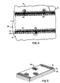
- Fig. 4 is a sectional view of a stent assembly embodying this invention, located in a passageway proximate a tumor; and
- Fig. 5 depicts an alternative embodiment of apparatus for generating electrical currents in accordance with this invention.
-
- In many patients who are terminally ill with cancer, it is important to maintain vessel patency, even for a limited time, with minimal trauma. As previously described, the option of using a stent with the fluid characteristics of a impermeable membrane may not always be viable. However, as shown in Fig. 1, prior art open mesh stents are subject to tumor incursion. As known, these stents comprise a wire filament knitted or otherwise formed into an open mesh with a cylindrical shape. Specifically, Fig. 1 depicts a prior art
open mesh stent 10 located in a vessel 11 through surroundingtissue 12 and proximate atumor 13. As thetumor 13 contacts theopen mesh stent 10, tumor cells can migrate through the open mesh of the stent walls and produce tumor extensions ormicro tumors 14 within thestent 10. As thesemicro tumors 14 grow, they partially occlude the vessel 11. Eventually they fully occlude the vessel 11 with the loss of function of the surroundingtissue 12. When this occurs, the resulting loss of function in the surrounding tissue may become life threatening. Under such circumstances the only practical alternative is to exchange the stent. As apparent, this requires the performance of a surgical procedure on a patient who may not be able to tolerate the procedure. - A
stent assembly 20 shown in Figs. 2 and 3 should maintain patency over a time interval of several months to a year or more without the need for iterative surgical processes. This stent assembly has the general from of an open-ended, closed wall structure and includes, as nested or concentric elements, an inner orcentral stent 21, anintermediate insulator 22 and anouter stent 23 that ton a three-layer cylindrical structure in this specific embodiment. The materials and construction of the inner stent andouter stents insulator 22 must meet a number of criteria. The primary criteria are that (1) the materials toning the inner andouter stents insulator 22 electrically isolates the inner andouter stents - When a
stent assembly 20 meeting these primary criteria is positioned in a vessel of the human body, it is immersed in an electrolytic fluid. For example, if thestent assembly 20 is located in a liver bile duct, the bile constitutes the electrolytic liquid. If thestent assembly 20 is located in the vascular network, blood constitutes the electrolytic liquid. It proximate cells from a structure that bridges portions of the inner andouter stents - Other material selection and construction criteria depend upon the specific application for the
stent assembly 20. For example, selected materials should be compatible with the biological environment. That is, each material should be physiologically inert or neutral in the environment. As now will be apparent, either theinner stent 21 or theouter stent 23 acts as a cathode. Electrolysis will erode the anode and, if the material if physiologically neutral, any by-products of electrolysis should not have an adverse impact on the patient. - The stent acting as the cathode must have sufficient strength to be self-supporting independently of the other stent. Again, electrolysis eventually destroys the anode stent, so the overall strength of the cathode stent must be sufficiently strong to maintain vessel patency. Material selection, filament size and mesh size all control strength. Tantalum stents of a variety of filament sizes and mesh configurations are self-supporting in a variety of applications. Thus, tantalum is a preferred cathode material in a variety of applications.
- The selected anode material and its construction must have an acceptable life expectancy. Once an anode material is selected, the mechanical design of the cathode controls life expectancy. For example, the selection of filament size and mesh size provides control over the life expectancy of an open-mesh stent. Iron is a preferred anode material. Silver is another possible anode material. It may have some beneficial healing properties, but the generated output voltage with a silver anode is less than with an iron anode. An anode of an aluminum-magnesium alloy will increase electrical output, but the stent assembly will have a life expectancy that is too short for many applications.
- The selection of mesh structure also impacts life expectancy and strength. This structure may take several well known forms. For example, each structure can comprise loosely interlocked loops that may be knitted as disclosed in the above-identified United States Letters Patent 4,922,905.
- The
intermediate insulator 22 can comprise any physiologically inert or neutral non-conductive material. Polymers, such as polyethylene, are suitable. The filament size and mesh size are not critical, except that the mesh size should be the smallest of the three elements thereby to assure the electrical isolation of theinner stent 21 and theouter stent 23. -
Stent assemblies 20 of tantalum and iron have been immersed in liver bile for testing. Open-circuit potentials of up to 100 millivolts or more have been measured. When a load resistor of 10,000 ohms is connected, thestent assembly 20 still produces an output voltage up to 15 millivolts. The resulting current has been found sufficient to alter cell growth. - Animal tests with stents constructed in accordance with the specific embodiment of Figs. 2 and 3, demonstrate that the location of this
stent 20 adjacent atumor 13, as shown in Fig. 4, maintains the patency of a vessel 11 for up to death due to carcinoma. Autopsies have demonstrated that the stents had maintained vessel patency through the progression of tumor growth. Apparently as tumor or other hyperplastic cells begin to transfer across the walls of thestent 20, they form a conductive path or bridge between theinner stent 21 and theouter stent 23. The resultant current, produced by electrolysis, disturbs the hyperplastic cell growth mechanism. Anymicro tumors 25 that begin to form terminate at theinner stent 21. As a result thestent assembly 20 inhibits the formation of micro tumors even though the assembly, as a whole, has the fluid characteristics of a permeable membrane. This enables liquids, such as liver bile and urine, to pass normally into the vessel 11 from surroundingtissue 12 thereby minimizing the potential for crystal formation. - A further understanding of the construction and operation of a stent assembly embodiment of this invention can be attained by reference to the following specific example having the form shown in Figs. 2 and 3 and being adapted for implantation in a liver bile duct.
Element Parameter Stent Elements Central Stent 21 Insulator 22Outer Stent 23Material Tantalum Polyethylene Iron Filament Diameter 0.1 mm .25 mm .125 mm Loop Size 6 loops 8 loops 6 loops 2 x 2 mm <1.7 mm 2.1 mm Outer Diameter Expanded 7-8 mm 7-8 mm 8 mm Other Criteria Must keep 2 stents apart - Fig. 5 discloses an alternative embodiment to the open-ended, closed wall, generally cylindrical structure of Fig. 1 in the form of a planar
electrical generator 30. Thegenerator 30 comprises aforaminous electrode 31, anintermediate insulator 32 and a secondforaminous electrode 33. Theelectrodes structure 30 is placed proximate a tumor or other portion of the body subject to hyperplastic cell growth in a flat orientation or conforming to the form of the tumor or region of hyperplastic cell growth, electrolytes (typically blood) in surrounding vessels will permeate the materials and increase the effectiveness of electrolysis. The foraminous nature of theelectrodes membrane 32 also facilitate the transfer of hyperplastic cells past the electrodes to form a conductive bridge and initiate current flow. - There have been disclosed specific embodiments of apparatus for the in situ generation of an electrical current in a biological environment in accordance with this invention, particularly one characterized by the actual or potential presence of hyperplastic cells. Each generator comprises electrodes having different electrochemical potentials that are separated by an insulating member. Fluids at the generator site constitute an electrolyte and hyperplastic cells that bridge the electrodes produce a current path. Electrolytic action then generates an electric current that passes through the current path and impedes hyperplastic cell growth. It has been observed that this current can terminate cell growth of a tumor proximate the generator.
- One particular embodiment comprises an electrolytic stent having inner and outer open mesh stents formed of different metals and an intermediate foraminous insulating member that separates the two metallic stents. This stent is particularly adapted for use in a vessel proximate a tumor. Fluid in the vessel acts as an electrolyte and tumor cells transporting across stent walls provide a current path. The resulting current prevents the formation of micro tumors that otherwise could partially or fully occlude the vessel.
- It will be apparent that a number of variations and modifications can be made to the specifically disclosed structures without departing from the scope of this invention as defined in the appended claims. The disclosure, for example, has described criteria for the selection of particular elements and has described specific materials that are adapted for use in humans. In other applications different elements can be used. There are disclosed apparatus in cylindrical and planar form; other forms can be used. Any or all of the specifically disclosed foraminous electrodes and insulators can be replaced by solid structures in other applications. Each such embodiment, however, will still be characterized by two electrodes of differing electrochemical potential and an intermediate insulator that isolates the electrodes from each other and will be constructed in accordance with this invention.
Claims (10)
- Apparatus for the in situ generation of an electrical current in an electrically conductive biological environment with an electrolyte and conductive tissue, said current generation apparatus comprising first (21,31) and second (23,33) superimposed layers of electrically conductive materials of different electrochemical potentials and an insulating third layer (22,32) interposed between said first and second layers to form a sandwich structure, whereby said first and second layers, when said apparatus is immersed in the electrolyte, generate electrolytically an electrical current for transfer through conductive tissue bridging said first and second layers.
- Apparatus as recited in claim 1, wherein each of the materials of said first (21,31), second (23,33) and third (22,32) layers is selected from a group of materials that are compatible with the biological environment including the conductive tissue and the electrolyte of the biological environment.
- Apparatus as recited in claim 1 or 2, wherein said first (21,31) and second (23,33) layers are materials selected from the group consisting of iron, tantalum and silver and an aluminum magnesium alloy.
- Apparatus as recited in claim 1, 2 or 3, wherein said insulating third. layer (22,32) is inert in the biological environment.
- Apparatus as recited in any preceding claim, wherein said conductive layers and insulating layer are foraminous and collectively form a permeable membrane through which proximate conductive tissue cells of the biological environment can expand to bridge said first and second layers, whereby said apparatus, when immersed in the electrolyte, generates electrolytically an electrical current through the bridging conductive tissue cells.
- Apparatus as recited in any of claims 1 to 4, wherein said conductive layers and insulating layer are mesh layers through which proximate conductive tissue cells of the biological environment can expand to bridge said first and second layers, whereby said apparatus, when immersed in the electrolyte, generates electrolytically an electrical current through the bridging conductive tissue cells.
- Apparatus as recited in any preceding claim, wherein at least one of said first and second layers provides a self-supporting structure.
- Apparatus as recited in any preceding claim, wherein said first (31), second (33) and third (32) layers collectively form a planar apparatus (30).
- Apparatus as recited in any of claims 1 to 7, wherein said first, second and third layers collectively form a substantially tubular wall structure.
- Apparatus as recited in claim 9, which comprises a stent assembly (20) for insertion in a vessel having a boundary vessel wall with conductive tissue cells and containing an electrolytic fluid, comprising, as a nested structure:said stent assembly, when inserted in a vessel, having a passage therethrough into which proximate conductive cells can expand, and forming an eletrolytic generator when the electrolytic fluid in the vessel contacts said stent assembly and when the conductive tissue cells form a conductive path bridging said inner and outer stents.A. an inner open mesh stent comprising said first layer (23);B. an outer open mesh stent comprising said second layer (23); andC. an intermediate open mesh insulating means comprising said third layer (22) for electrically isolating said inner and outer stents from each other;
Applications Claiming Priority (3)
| Application Number | Priority Date | Filing Date | Title |
|---|---|---|---|
| US847911 | 1992-03-09 | ||
| US07/847,911 US5360440A (en) | 1992-03-09 | 1992-03-09 | In situ apparatus for generating an electrical current in a biological environment |
| PCT/US1993/002233 WO1993017752A1 (en) | 1992-03-09 | 1993-03-03 | Biological in situ electrical current generating apparatus |
Publications (3)
| Publication Number | Publication Date |
|---|---|
| EP0633800A1 EP0633800A1 (en) | 1995-01-18 |
| EP0633800A4 EP0633800A4 (en) | 1995-12-06 |
| EP0633800B1 true EP0633800B1 (en) | 2000-09-13 |
Family
ID=25301802
Family Applications (1)
| Application Number | Title | Priority Date | Filing Date |
|---|---|---|---|
| EP93908311A Expired - Lifetime EP0633800B1 (en) | 1992-03-09 | 1993-03-03 | Biological in situ electrical current generating apparatus |
Country Status (6)
| Country | Link |
|---|---|
| US (1) | US5360440A (en) |
| EP (1) | EP0633800B1 (en) |
| JP (1) | JPH07504585A (en) |
| CA (1) | CA2131706A1 (en) |
| DE (1) | DE69329420T2 (en) |
| WO (1) | WO1993017752A1 (en) |
Families Citing this family (90)
| Publication number | Priority date | Publication date | Assignee | Title |
|---|---|---|---|---|
| US5662713A (en) * | 1991-10-09 | 1997-09-02 | Boston Scientific Corporation | Medical stents for body lumens exhibiting peristaltic motion |
| US7101392B2 (en) * | 1992-03-31 | 2006-09-05 | Boston Scientific Corporation | Tubular medical endoprostheses |
| US5728068A (en) * | 1994-06-14 | 1998-03-17 | Cordis Corporation | Multi-purpose balloon catheter |
| US5814094A (en) | 1996-03-28 | 1998-09-29 | Becker; Robert O. | Iontopheretic system for stimulation of tissue healing and regeneration |
| US6861570B1 (en) | 1997-09-22 | 2005-03-01 | A. Bart Flick | Multilayer conductive appliance having wound healing and analgesic properties |
| US8455710B2 (en) * | 1997-09-22 | 2013-06-04 | Argentum Medical, Llc | Conductive wound dressings and methods of use |
| US8801681B2 (en) * | 1995-09-05 | 2014-08-12 | Argentum Medical, Llc | Medical device |
| US7214847B1 (en) | 1997-09-22 | 2007-05-08 | Argentum Medical, L.L.C. | Multilayer conductive appliance having wound healing and analgesic properties |
| US6135953A (en) * | 1996-01-25 | 2000-10-24 | 3M Innovative Properties Company | Multi-functional biomedical electrodes |
| US6385487B1 (en) | 1996-05-08 | 2002-05-07 | Biophoretic Therapeutic Systems, Llc | Methods for electrokinetic delivery of medicaments |
| US5676648A (en) | 1996-05-08 | 1997-10-14 | The Aps Organization, Llp | Iontophoretic drug delivery apparatus and method for use |
| US6021347A (en) * | 1996-12-05 | 2000-02-01 | Herbst; Ewa | Electrochemical treatment of malignant tumors |
| US6708066B2 (en) * | 1999-12-10 | 2004-03-16 | Ewa Herbst | Electrochemical treatment of tissues, especially tumors |
| USRE37796E1 (en) | 1997-12-16 | 2002-07-23 | Biophoretic Therapeutic Systems, Llc | Methods for iontophoretic delivery of antiviral agents |
| US5976169A (en) * | 1997-12-16 | 1999-11-02 | Cardiovasc, Inc. | Stent with silver coating and method |
| US20030036746A1 (en) | 2001-08-16 | 2003-02-20 | Avi Penner | Devices for intrabody delivery of molecules and systems and methods utilizing same |
| US5873907A (en) | 1998-01-27 | 1999-02-23 | Endotex Interventional Systems, Inc. | Electrolytic stent delivery system and methods of use |
| US6112122A (en) * | 1998-11-17 | 2000-08-29 | Electro-Biology, Inc. | Preformed extendable mesh cathode for implantable bone growth stimulator |
| US6792306B2 (en) | 2000-03-10 | 2004-09-14 | Biophoretic Therapeutic Systems, Llc | Finger-mounted electrokinetic delivery system for self-administration of medicaments and methods therefor |
| US7127285B2 (en) | 1999-03-12 | 2006-10-24 | Transport Pharmaceuticals Inc. | Systems and methods for electrokinetic delivery of a substance |
| US6477410B1 (en) | 2000-05-31 | 2002-11-05 | Biophoretic Therapeutic Systems, Llc | Electrokinetic delivery of medicaments |
| DE19912635A1 (en) * | 1999-03-20 | 2000-09-21 | Biotronik Mess & Therapieg | Dilatable cardiac electrode arrangement for implantation, particularly in the coronary sinus of the heart |
| US6902564B2 (en) * | 2001-08-15 | 2005-06-07 | Roy E. Morgan | Methods and devices for electrosurgery |
| US7445619B2 (en) * | 2000-08-18 | 2008-11-04 | Map Technologies Llc | Devices for electrosurgery |
| US7771422B2 (en) * | 2002-06-06 | 2010-08-10 | Nuortho Surgical, Inc. | Methods and devices for electrosurgery |
| US7819861B2 (en) * | 2001-05-26 | 2010-10-26 | Nuortho Surgical, Inc. | Methods for electrosurgical electrolysis |
| US7066932B1 (en) | 2001-05-26 | 2006-06-27 | Map Technologies Llc | Biologically enhanced irrigants |
| WO2003002243A2 (en) * | 2001-06-27 | 2003-01-09 | Remon Medical Technologies Ltd. | Method and device for electrochemical formation of therapeutic species in vivo |
| WO2003003948A1 (en) * | 2001-07-06 | 2003-01-16 | Tricardia, L.L.C. | Anti-arrhythmia devices and methods of use |
| US8734441B2 (en) | 2001-08-15 | 2014-05-27 | Nuortho Surgical, Inc. | Interfacing media manipulation with non-ablation radiofrequency energy system and method |
| US8591508B2 (en) | 2001-08-15 | 2013-11-26 | Nuortho Surgical, Inc. | Electrosurgical plenum |
| US8235979B2 (en) | 2001-08-15 | 2012-08-07 | Nuortho Surgical, Inc. | Interfacing media manipulation with non-ablation radiofrequency energy system and method |
| US20030135262A1 (en) * | 2002-01-15 | 2003-07-17 | Dretler Stephen P. | Apparatus for piezo-electric reduction of concretions |
| US7918883B2 (en) * | 2002-02-25 | 2011-04-05 | Boston Scientific Scimed, Inc. | Non-invasive heating of implanted vascular treatment device |
| US20040002752A1 (en) * | 2002-06-26 | 2004-01-01 | Scimed Life Systems, Inc. | Sacrificial anode stent system |
| US20050256549A1 (en) * | 2002-10-09 | 2005-11-17 | Sirius Implantable Systems Ltd. | Micro-generator implant |
| US20040106951A1 (en) * | 2002-11-22 | 2004-06-03 | Edman Carl Frederick | Use of electric fields to minimize rejection of implanted devices and materials |
| EP1605866B1 (en) | 2003-03-03 | 2016-07-06 | Syntach AG | Electrical conduction block implant device |
| WO2004078066A2 (en) | 2003-03-03 | 2004-09-16 | Sinus Rhythm Technologies, Inc. | Primary examiner |
| WO2004098511A2 (en) * | 2003-05-01 | 2004-11-18 | Sinus Rhythm Technologies, Inc. | Methods and devices for creating electrical block at specific targeted sites in cardia tissue |
| WO2005039689A2 (en) * | 2003-10-24 | 2005-05-06 | Sinus Rhythm Technologies, Inc. | Methods and devices for creating cardiac electrical blocks |
| SE526861C2 (en) | 2003-11-17 | 2005-11-15 | Syntach Ag | Tissue lesion creation device and a set of devices for the treatment of cardiac arrhythmia disorders |
| DE10361940A1 (en) * | 2003-12-24 | 2005-07-28 | Restate Patent Ag | Degradation control of biodegradable implants by coating |
| US7662176B2 (en) * | 2004-02-19 | 2010-02-16 | Vomaris Innovations, Inc. | Footwear apparatus and methods of manufacture and use |
| US7457667B2 (en) * | 2004-02-19 | 2008-11-25 | Silverleaf Medical Products, Inc. | Current producing surface for a wound dressing |
| US9398967B2 (en) | 2004-03-02 | 2016-07-26 | Syntach Ag | Electrical conduction block implant device |
| EP1768740A4 (en) * | 2004-06-02 | 2007-10-31 | Carl Frederick Edman | Use of electric fields to minimize rejection of implanted devices and materials |
| US8271093B2 (en) | 2004-09-17 | 2012-09-18 | Cardiac Pacemakers, Inc. | Systems and methods for deriving relative physiologic measurements using a backend computing system |
| EP1809195A4 (en) * | 2004-10-08 | 2010-01-20 | Syntach Ag | Two-stage scar generation for treating atrial fibrillation |
| US20060106451A1 (en) * | 2004-11-18 | 2006-05-18 | Yuri Busiashvili | Electronic anti-coagulation stent for intra-arterial deployment |
| US7813808B1 (en) | 2004-11-24 | 2010-10-12 | Remon Medical Technologies Ltd | Implanted sensor system with optimized operational and sensing parameters |
| EP1797843A1 (en) * | 2005-12-14 | 2007-06-20 | Thomas Ischinger | Lesion specific stents, also for ostial lesions, and methods of application |
| US8840660B2 (en) | 2006-01-05 | 2014-09-23 | Boston Scientific Scimed, Inc. | Bioerodible endoprostheses and methods of making the same |
| US8089029B2 (en) | 2006-02-01 | 2012-01-03 | Boston Scientific Scimed, Inc. | Bioabsorbable metal medical device and method of manufacture |
| US8048150B2 (en) | 2006-04-12 | 2011-11-01 | Boston Scientific Scimed, Inc. | Endoprosthesis having a fiber meshwork disposed thereon |
| US20070270942A1 (en) * | 2006-05-19 | 2007-11-22 | Medtronic Vascular, Inc. | Galvanic Corrosion Methods and Devices for Fixation of Stent Grafts |
| US7955268B2 (en) | 2006-07-21 | 2011-06-07 | Cardiac Pacemakers, Inc. | Multiple sensor deployment |
| EP2054537A2 (en) | 2006-08-02 | 2009-05-06 | Boston Scientific Scimed, Inc. | Endoprosthesis with three-dimensional disintegration control |
| EP2210625B8 (en) | 2006-09-15 | 2012-02-29 | Boston Scientific Scimed, Inc. | Bioerodible endoprosthesis with biostable inorganic layers |
| EP2081616B1 (en) | 2006-09-15 | 2017-11-01 | Boston Scientific Scimed, Inc. | Bioerodible endoprostheses and methods of making the same |
| CA2663220A1 (en) | 2006-09-15 | 2008-03-20 | Boston Scientific Limited | Medical devices and methods of making the same |
| JP2010503494A (en) | 2006-09-15 | 2010-02-04 | ボストン サイエンティフィック リミテッド | Biodegradable endoprosthesis and method for producing the same |
| US8002821B2 (en) | 2006-09-18 | 2011-08-23 | Boston Scientific Scimed, Inc. | Bioerodible metallic ENDOPROSTHESES |
| US20080122582A1 (en) * | 2006-11-29 | 2008-05-29 | Texas Instruments Incorporated | Location Based Portable Device Feature Disabler |
| ES2506144T3 (en) | 2006-12-28 | 2014-10-13 | Boston Scientific Limited | Bioerodible endoprosthesis and their manufacturing procedure |
| US8052745B2 (en) | 2007-09-13 | 2011-11-08 | Boston Scientific Scimed, Inc. | Endoprosthesis |
| US8623071B2 (en) * | 2008-01-07 | 2014-01-07 | DePuy Synthes Products, LLC | Radiopaque super-elastic intravascular stent |
| US7998192B2 (en) | 2008-05-09 | 2011-08-16 | Boston Scientific Scimed, Inc. | Endoprostheses |
| US8236046B2 (en) | 2008-06-10 | 2012-08-07 | Boston Scientific Scimed, Inc. | Bioerodible endoprosthesis |
| EP2307069A2 (en) * | 2008-06-25 | 2011-04-13 | Boston Scientific Scimed, Inc. | Medical devices for delivery of therapeutic agent in conjunction with galvanic corrosion |
| US7985252B2 (en) | 2008-07-30 | 2011-07-26 | Boston Scientific Scimed, Inc. | Bioerodible endoprosthesis |
| US8382824B2 (en) | 2008-10-03 | 2013-02-26 | Boston Scientific Scimed, Inc. | Medical implant having NANO-crystal grains with barrier layers of metal nitrides or fluorides |
| EP2403546A2 (en) | 2009-03-02 | 2012-01-11 | Boston Scientific Scimed, Inc. | Self-buffering medical implants |
| US9532827B2 (en) | 2009-06-17 | 2017-01-03 | Nuortho Surgical Inc. | Connection of a bipolar electrosurgical hand piece to a monopolar output of an electrosurgical generator |
| US20110196478A1 (en) * | 2010-02-10 | 2011-08-11 | Beoptima Inc. | Devices and methods for lumen treatment |
| WO2011100547A2 (en) * | 2010-02-11 | 2011-08-18 | Boston Scientific Scimed, Inc. | Automatic vascular closure deployment devices and methods |
| US8668732B2 (en) | 2010-03-23 | 2014-03-11 | Boston Scientific Scimed, Inc. | Surface treated bioerodible metal endoprostheses |
| US9414821B2 (en) | 2010-07-22 | 2016-08-16 | Boston Scientific Scimed, Inc. | Vascular closure device with biodegradable anchor |
| US8758402B2 (en) | 2010-12-17 | 2014-06-24 | Boston Scientific Scimed, Inc. | Tissue puncture closure device |
| US9408658B2 (en) | 2011-02-24 | 2016-08-09 | Nuortho Surgical, Inc. | System and method for a physiochemical scalpel to eliminate biologic tissue over-resection and induce tissue healing |
| US9579142B1 (en) | 2012-12-13 | 2017-02-28 | Nuortho Surgical Inc. | Multi-function RF-probe with dual electrode positioning |
| US9320592B2 (en) | 2013-03-15 | 2016-04-26 | Covidien Lp | Coated medical devices and methods of making and using same |
| US9545301B2 (en) | 2013-03-15 | 2017-01-17 | Covidien Lp | Coated medical devices and methods of making and using same |
| US9668890B2 (en) | 2013-11-22 | 2017-06-06 | Covidien Lp | Anti-thrombogenic medical devices and methods |
| US9789228B2 (en) | 2014-12-11 | 2017-10-17 | Covidien Lp | Antimicrobial coatings for medical devices and processes for preparing such coatings |
| US10076430B2 (en) * | 2015-10-19 | 2018-09-18 | Cook Medical Technologies Llc | Devce with tensioners |
| US11122971B2 (en) | 2016-08-18 | 2021-09-21 | Neptune Medical Inc. | Device and method for enhanced visualization of the small intestine |
| KR101815783B1 (en) * | 2016-08-26 | 2018-01-08 | 가톨릭대학교 산학협력단 | Stent Using Wireless Transmitted Power |
| WO2019232354A1 (en) * | 2018-05-31 | 2019-12-05 | Neptune Medical Inc. | Device and method for enhanced visualization of the small intestine |
| US20230346205A1 (en) | 2022-04-27 | 2023-11-02 | Neptune Medical Inc. | Multi-lumen port adapter manifold devices and methods of use |
Family Cites Families (8)
| Publication number | Priority date | Publication date | Assignee | Title |
|---|---|---|---|---|
| US4886505A (en) * | 1985-06-07 | 1989-12-12 | Becton, Dickinson And Company | Antimicrobial surfaces and inhibition of microorganism growth thereby |
| EP0227754A4 (en) * | 1985-06-20 | 1987-11-10 | Noel Desmond Gray | Internally applied self energising healing electrodes. |
| US4733665C2 (en) * | 1985-11-07 | 2002-01-29 | Expandable Grafts Partnership | Expandable intraluminal graft and method and apparatus for implanting an expandable intraluminal graft |
| DE3640745A1 (en) * | 1985-11-30 | 1987-06-04 | Ernst Peter Prof Dr M Strecker | Catheter for producing or extending connections to or between body cavities |
| FI85101C (en) * | 1989-10-27 | 1992-03-10 | Instrumentarium Oy Datex | FOER OBSERVATION AV ANDNING LAEMPLIG AVKAENNINGSORGAN. |
| US5078736A (en) * | 1990-05-04 | 1992-01-07 | Interventional Thermodynamics, Inc. | Method and apparatus for maintaining patency in the body passages |
| US5108417A (en) * | 1990-09-14 | 1992-04-28 | Interface Biomedical Laboratories Corp. | Anti-turbulent, anti-thrombogenic intravascular stent |
| CS277367B6 (en) * | 1990-12-29 | 1993-01-13 | Krajicek Milan | Three-layered vascular prosthesis |
-
1992
- 1992-03-09 US US07/847,911 patent/US5360440A/en not_active Expired - Lifetime
-
1993
- 1993-03-03 CA CA002131706A patent/CA2131706A1/en not_active Abandoned
- 1993-03-03 DE DE69329420T patent/DE69329420T2/en not_active Expired - Fee Related
- 1993-03-03 EP EP93908311A patent/EP0633800B1/en not_active Expired - Lifetime
- 1993-03-03 WO PCT/US1993/002233 patent/WO1993017752A1/en active IP Right Grant
- 1993-03-03 JP JP5516007A patent/JPH07504585A/en active Pending
Also Published As
| Publication number | Publication date |
|---|---|
| JPH07504585A (en) | 1995-05-25 |
| WO1993017752A1 (en) | 1993-09-16 |
| DE69329420D1 (en) | 2000-10-19 |
| EP0633800A4 (en) | 1995-12-06 |
| CA2131706A1 (en) | 1993-09-16 |
| DE69329420T2 (en) | 2001-03-08 |
| US5360440A (en) | 1994-11-01 |
| EP0633800A1 (en) | 1995-01-18 |
Similar Documents
| Publication | Publication Date | Title |
|---|---|---|
| EP0633800B1 (en) | Biological in situ electrical current generating apparatus | |
| CA2555011C (en) | Enhancing tissue ingrowth for contraception | |
| US20210275186A1 (en) | Detachment Mechanisms for Attachment Devices | |
| CN102341145B (en) | Atraumatic lead removal sheath | |
| JP5905409B2 (en) | MRT compatible valve prosthesis used in human or animal body for organ valve or vascular valve replacement | |
| US8118857B2 (en) | Medical articles that stimulate endothelial cell migration | |
| US20100185268A1 (en) | Implantable medical devices and associated systems and methods | |
| EP3134140B1 (en) | Bioerodible stent | |
| Brighton et al. | Ultrastructure of electrically induced osteogenesis in the rabbit medullary canal | |
| Arsiwala et al. | Nanocoatings on implantable medical devices | |
| CN106726038B (en) | A kind of aorta ascendens inner cavity insulation transplantation device | |
| US11925571B2 (en) | Stent device with stent covering with regions of differing porosity | |
| Cwikiel et al. | Electrolytic stents to inhibit tumor growth: An experimental study in vitro and in rats | |
| CN107530087A (en) | Stream electricity auxiliary aneurysm treatment | |
| Hohmann et al. | LXVI Fate of Implants in Rats | |
| JP2003260142A (en) | Stent for intracranial blood vessel treatment, and production method | |
| CN220632144U (en) | Suture line device | |
| KR20120047578A (en) | Implant battery having tube structure | |
| US20200093967A1 (en) | Implantable device for modulating localized ph at implantation site | |
| JP2012224585A (en) | Agent sustained release member, and medical equipment | |
| JP2012061191A (en) | Drug eluting member and medical device |
Legal Events
| Date | Code | Title | Description |
|---|---|---|---|
| PUAI | Public reference made under article 153(3) epc to a published international application that has entered the european phase |
Free format text: ORIGINAL CODE: 0009012 |
|
| 17P | Request for examination filed |
Effective date: 19940929 |
|
| AK | Designated contracting states |
Kind code of ref document: A1 Designated state(s): DE FR GB IT |
|
| A4 | Supplementary search report drawn up and despatched |
Effective date: 19951018 |
|
| AK | Designated contracting states |
Kind code of ref document: A4 Designated state(s): DE FR GB IT |
|
| RAP1 | Party data changed (applicant data changed or rights of an application transferred) |
Owner name: BOSTON SCIENTIFIC CORPORATION |
|
| RAP3 | Party data changed (applicant data changed or rights of an application transferred) |
Owner name: BOSTON SCIENTIFIC CORPORATION |
|
| 17Q | First examination report despatched |
Effective date: 19980119 |
|
| GRAG | Despatch of communication of intention to grant |
Free format text: ORIGINAL CODE: EPIDOS AGRA |
|
| GRAG | Despatch of communication of intention to grant |
Free format text: ORIGINAL CODE: EPIDOS AGRA |
|
| GRAG | Despatch of communication of intention to grant |
Free format text: ORIGINAL CODE: EPIDOS AGRA |
|
| GRAH | Despatch of communication of intention to grant a patent |
Free format text: ORIGINAL CODE: EPIDOS IGRA |
|
| GRAH | Despatch of communication of intention to grant a patent |
Free format text: ORIGINAL CODE: EPIDOS IGRA |
|
| GRAA | (expected) grant |
Free format text: ORIGINAL CODE: 0009210 |
|
| AK | Designated contracting states |
Kind code of ref document: B1 Designated state(s): DE FR GB IT |
|
| PG25 | Lapsed in a contracting state [announced via postgrant information from national office to epo] |
Ref country code: IT Free format text: LAPSE BECAUSE OF FAILURE TO SUBMIT A TRANSLATION OF THE DESCRIPTION OR TO PAY THE FEE WITHIN THE PRESCRIBED TIME-LIMIT;WARNING: LAPSES OF ITALIAN PATENTS WITH EFFECTIVE DATE BEFORE 2007 MAY HAVE OCCURRED AT ANY TIME BEFORE 2007. THE CORRECT EFFECTIVE DATE MAY BE DIFFERENT FROM THE ONE RECORDED. Effective date: 20000913 |
|
| REF | Corresponds to: |
Ref document number: 69329420 Country of ref document: DE Date of ref document: 20001019 |
|
| ET | Fr: translation filed | ||
| PLBE | No opposition filed within time limit |
Free format text: ORIGINAL CODE: 0009261 |
|
| STAA | Information on the status of an ep patent application or granted ep patent |
Free format text: STATUS: NO OPPOSITION FILED WITHIN TIME LIMIT |
|
| 26N | No opposition filed | ||
| REG | Reference to a national code |
Ref country code: GB Ref legal event code: IF02 |
|
| PGFP | Annual fee paid to national office [announced via postgrant information from national office to epo] |
Ref country code: GB Payment date: 20080211 Year of fee payment: 16 |
|
| PGFP | Annual fee paid to national office [announced via postgrant information from national office to epo] |
Ref country code: FR Payment date: 20080307 Year of fee payment: 16 Ref country code: DE Payment date: 20080331 Year of fee payment: 16 |
|
| GBPC | Gb: european patent ceased through non-payment of renewal fee |
Effective date: 20090303 |
|
| PG25 | Lapsed in a contracting state [announced via postgrant information from national office to epo] |
Ref country code: DE Free format text: LAPSE BECAUSE OF NON-PAYMENT OF DUE FEES Effective date: 20091001 |
|
| PG25 | Lapsed in a contracting state [announced via postgrant information from national office to epo] |
Ref country code: GB Free format text: LAPSE BECAUSE OF NON-PAYMENT OF DUE FEES Effective date: 20090303 |
|
| REG | Reference to a national code |
Ref country code: FR Ref legal event code: ST Effective date: 20100531 |
|
| PG25 | Lapsed in a contracting state [announced via postgrant information from national office to epo] |
Ref country code: FR Free format text: LAPSE BECAUSE OF NON-PAYMENT OF DUE FEES Effective date: 20090331 |