EP0634725B1 - Noeud de processeurs - Google Patents
Noeud de processeurs Download PDFInfo
- Publication number
- EP0634725B1 EP0634725B1 EP94401598A EP94401598A EP0634725B1 EP 0634725 B1 EP0634725 B1 EP 0634725B1 EP 94401598 A EP94401598 A EP 94401598A EP 94401598 A EP94401598 A EP 94401598A EP 0634725 B1 EP0634725 B1 EP 0634725B1
- Authority
- EP
- European Patent Office
- Prior art keywords
- node
- processors
- local
- bus
- nodes
- Prior art date
- Legal status (The legal status is an assumption and is not a legal conclusion. Google has not performed a legal analysis and makes no representation as to the accuracy of the status listed.)
- Expired - Lifetime
Links
Images


Classifications
-
- G—PHYSICS
- G06—COMPUTING; CALCULATING OR COUNTING
- G06F—ELECTRIC DIGITAL DATA PROCESSING
- G06F15/00—Digital computers in general; Data processing equipment in general
- G06F15/76—Architectures of general purpose stored program computers
- G06F15/80—Architectures of general purpose stored program computers comprising an array of processing units with common control, e.g. single instruction multiple data processors
- G06F15/8007—Architectures of general purpose stored program computers comprising an array of processing units with common control, e.g. single instruction multiple data processors single instruction multiple data [SIMD] multiprocessors
- G06F15/803—Three-dimensional arrays or hypercubes
-
- G—PHYSICS
- G06—COMPUTING; CALCULATING OR COUNTING
- G06F—ELECTRIC DIGITAL DATA PROCESSING
- G06F15/00—Digital computers in general; Data processing equipment in general
- G06F15/16—Combinations of two or more digital computers each having at least an arithmetic unit, a program unit and a register, e.g. for a simultaneous processing of several programs
- G06F15/163—Interprocessor communication
- G06F15/173—Interprocessor communication using an interconnection network, e.g. matrix, shuffle, pyramid, star, snowflake
- G06F15/17356—Indirect interconnection networks
- G06F15/17368—Indirect interconnection networks non hierarchical topologies
- G06F15/17381—Two dimensional, e.g. mesh, torus
Definitions
- the present invention relates to a processor node.
- An object of the invention is to propose a knot processor with an original structure improving message rates regardless of the technology used for making memory blocks or link buses.
- a processor node is proposed. as defined in claim 1.
- the local bus is only used for the transmission of messages directly useful to processors while the network bus is used for the transmission of link messages with other nodes so that one minimizes the number of messages circulating on each bus. All minimizing the message throughput we note that this provision nevertheless allows simultaneous access to memory local and cache shared by both the local bus and the network bus.
- the processor node has at least one controller serial links connected to the network bus and ensuring a relationship with an adjacent node or, where appropriate, an input / output member. So, in the transmission of messages inside the node, we benefits from the low latency of the parallel bus to have a quick access to local information and we take advantage of the speed high serial links to update information which are stored in local memory and in the cache shared and put news in the shared cache copies of information held in the local memory of a another node in order to benefit from the low latency of the internal parallel link at the node.
- the knot has two local buses, each associated with the processors, a shared cache and a local memory, and two network buses also each associated with a shared cache and a memory local. So without increasing the number of takes required on each bus, we increase the total message capacity can be transmitted between the processors on the one hand and the shared cache and local memory on the other hand.
- the computer system is a shared memory assembly, that is to say a set in which the general memory to which all processors must be able to have access is distributed according to local memories to which each of the processors can have direct or indirect access, processors being themselves grouped according to associated nodes between them by connections.
- the nodes of processors have the general reference numeral 1 and, according to one aspect of the invention, the set of nodes 1 is divided according to super nodes with the numerical reference general 2.
- the set illustrated has four super knots 2 each comprising eight nodes 1.
- the general reference is associated with a particular reference.
- each node 1 has a special reference identifying it on the one hand by the super node to which it belongs (first digit of the particular reference) and on the other hand by its number order in the super node (second digit of the reference particular). So the first node of the first super node bears the complete reference 1.11, the second node of the first super node carries the full reference 1.12, the third node of the first super node carries the complete reference 1.13 ....
- the first node of the second super node 2.2 carries the complete reference 1.21, the second node of the second super node 2.2 carries the complete reference 1.22 ).
- Each super node 2 is divided into two subsets 3 marked by a dashed line for the super node 2.1.
- the first subset the super node 2.1 which includes the nodes 1.11, 1.12, 1.13 and 1.14, has the full reference 3.11 and the second subset which includes nodes 1.15, 1.16, 1.17 and 1.18, bears the full reference 3.12.
- the nodes are connected them to each other by series 4 links illustrated by a thick solid line when using a serial link double and with a thin continuous line when it is a simple serial link.
- a simple serial link within the meaning of this description is, usually consisting of two shielded differential pairs forming a single logical link and represented as such by a single line in the figures.
- nodes of a subset 3 are interconnected by double serial links and are connected to the nodes of an adjacent subset of the same super node 2 by simple serial links.
- node 1.11 is connected by double serial links to each of the nodes 1.12, 1.13 and 1.14 of the same subset 3.11, and by simple connections to nodes 1.15, 1.16, 1.17 and 1.18 of the subset adjacent 3.12 of the same super node 2.1.
- the super nodes 2 are linked in pairs by serial links duplicates associating each node of a super node with a node correspondent of another super knot. So the two super nodes 2.1 and 2.2 are paired by establishing a connection double between node 1.11 and node 1.21, between node 1.12 and the node 1.22 altogether these double bonds not being marked in the figure only for the extreme lateral knots of the schematic representation illustrated and being marked only by a thick line start for the others knots. Similarly, super nodes 2.3 and 2.4 are paired by double links respectively connecting the node 1.31 at node 1.41, node 1.32 at node 1.42 ....
- each pair of associated super nodes is linked to another pair of super nodes associated by simple serial links connecting each node of a pair to two matching nodes from the other pair.
- knot 1.11 is connected by a simple serial link to node 1.31 and at node 1.41 ...
- node 1.21 is also connected by a simple serial link at node 1.31 and at node 1.41 .... same as before for double bonds between two super paired nodes, simple links between two pairs super knots have been marked in the figure only for the extreme lateral nodes, the other simple links being only marked by a fine line start from of each node.
- the computer assembly according to the invention further comprises a super node 5 of input / output devices bearing the reference general 6, each input / output member 6 being connected by a serial link 4 to a corresponding node of each super knots.
- the organs input / output respectively have the references complete digital 6.1, 6.2 .
- the input / output device 6.1 is connected by simple serial links 4 to the nodes 1.11, 1.21, 1.31 and 1.41; the input / output device 6.2 is connected to nodes 1.12, 1.22, 1.32 and 1.42 .... and, within super node 5, the input / output devices are also linked together by a simple serial link 7.
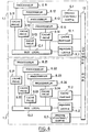
- FIG. 2 schematically illustrates the structure of an embodiment of a node according to the invention.
- each node comprises four processors with general reference 8 and one particular reference to identify in relation to node to which it belongs (first two digits of the particular reference), and by its serial number in the node (last digit of the particular reference).
- Figure 2 illustrates the structure of node 1.11 and, to identify each of the processors in relationship with this node, these bear the references complete numeric numbers 8.111.8.112, 8.113 and 8.114.
- full processor references will be 8.431, 8.432, 8.433 and 8.434.
- Each processor is associated with a private cache with the general reference 9, and respectively the complete references 9.111, 9.112, 9.113 and 9.114.
- cache is commonly used to designate a memory containing information which is copies of information originally held at a address of the general memory of the computer system so that a particular instruction processor can use this information faster than if he had to systematically question the general memory at every time he executes an instruction implementing this information.
- the private cache term will be used for a cache to which a instruction processor is directly connected.
- Each private caches 9 is connected to two local buses carrying the general reference 10 and, respectively, the references 10.111 and 10.112.
- local memory is used for a memory comprising a part of general memory, i.e. part of original information accessible by all microprocessors.
- shared cache is used to designate a memory that contains copies of information contained in the local memories of the other nodes of the computer system and which is intended to be used by the different processors of the node in which the cache shared is willing.
- private caches, shared caches and local memories include management processors that were not represented on the figures.
- Each private cache is a level 1 memory higher in the hierarchy for a node considered, each shared cache is a second level memory of the hierarchy for the node considered and each local memory is so a second level memory of the hierarchy for the considered node and third level of the hierarchy for the other nodes.
- the part of general memory associated with the node has been subdivided in two local memories, the even local memory 11,111 which contains the information at even addresses and that is associated with the even local bus 10.111, and the local memory odd 11,112 which contains information held at odd addresses and which is connected to the odd local bus 1.112.
- the shared cache associated with the node has been divided into an even shared cache 12,111 containing copies even address information, and connected to the even local bus 10.111, and the odd shared cache 12.112 containing copies of information to odd addresses and connected to the bus odd local 10.112.
- Each local memory and each cache shared is connected to a network bus 13 providing a link parallel, respectively 13.111 for the even network bus and 13.112 for the odd network bus.
- the network buses are linked to serial links 14, respectively 14.111, 14.112, 14.113 and 14.114 in the illustrated embodiment.
- the controllers of serial links 14 provide an interface between the buses networks and the serial links 4 which provide the links between the nodes.
- the link controllers series 14 are connected to each of the network buses 13.
- each node is associated with other nodes, and to the input / output organs by a total of 15 serial links.
- Network buses could be linked to serial links via an interface with a single serial link controller. However, for reasons technological, the power consumed would be too large and would cause an unacceptable heating of this interface. This is the reason why the interface between network buses and serial links has been subdivided into four serial link controllers.
- each bus parallel type whether local buses or buses networks is equipped with six sockets, which ensures a sufficient message throughput without unduly increasing the complexity of the protocols for transmitting these messages.
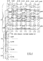
- Figure 4 illustrates the distribution of links between the serial link controllers of the same super node and with the serial link controllers of the other super nodes with which a super node is associated.
- the lines between serial link controllers and buses networks were not represented.
- the distribution of the serial links between the serial link controllers of the first super node 2.1 and, for the connections with the other super nodes we have represented only the distribution of serial links between the node 1.11 and the corresponding serial link controllers other super knots.
- each link controller series is represented by a dashed rectangle and the connections of a serial link 4 with a serial links are represented by a solid line for each single serial link.
- the first controller serial links of node 1.11 carries the complete reference 14.111 while the first serial link controller of the node 1.12 carries the complete reference 14.121 whereas the second 1.11 serial link controller carries the reference 14.112, the second link controller 1.12 node series carries the full reference 1.122 ....
- the double serial link connecting node 1.11 with node 1.12 is illustrated by a simple serial link connecting the serial link controller 14.111 and the serial link controller 14.121 and a simple serial link connecting the serial link controller 14.112 and the serial link controller 14.122;
- the double serial link connecting node 1.11 to node 1.14 is illustrated by a simple link connecting the controller serial links 14.113 to the serial link controller 14.143 and a simple serial link connecting the controller 14.114 serial links to the serial link controller 14,144;
- the double serial link connecting node 1.11 and the node 1.21 is illustrated by a simple serial link connecting the serial link controller 14.111 and the 14.211 serial links, and a single serial link connecting the serial link controller 14.114 to the serial links 14.214.
- the simple serial link connecting the node 1.11 at node 1.31 is illustrated by the serial link simple connecting the serial link controller 14.113 to 14.313 serial link controller, and the serial link simple connecting node 1.11 to node 1.41 is illustrated by the simple serial link connecting the link controller 14.112 to the 14.412 serial link controller.
- the serial link controller 14.113 includes in addition to a terminal connected to the serial link controller the input device 6.1, and which has not been shown on the figure.
- the serial link controller 14.114 has a unassigned terminal which can, if necessary, be used to ensure a double serial link between node 1.11 and the organ input / output 6.1.
- connections thus established allow to go from any node to another node using only two serial links.
- node 1.11 to node 1.33 using first one of the serial links from node 1.11 to node 1.13 then the serial link connecting node 1.13 to node 1.33.
- node 1.35 to node 1.22 using the serial link from node 1.35 to node 1.32 then the link series from node 1.32 to node 1.22.
- this property is also obtained for the binding of any of input / output devices with any of the nodes.
- an input / output device is not usually intended to work with all of nodes and we can therefore save links by removing those which connect the input / output members together.
- FIG. 3 partially illustrates a alternative embodiment of the knot illustrated in FIG. 2 allowing to double the number of processors in the node without increasing the number of sockets on local buses and without otherwise changing the links between the nodes.
- each of the processors and the private cache associated with it is replaced by two processors each associated with a private cache.
- Figure 3 illustrates the splitting of the processor 8.111 in FIG. 2, identical duplication being of course carried out for other processors on the same node so as not to complicate improperly handling messages with the node.
- the 8.111 processor is therefore replaced by an 8.1111 processor and a processor 8.1112 respectively connected to a cache private 9.1111 and a private cache 9.1112.
- Each private cache is connected to two interfaces 15 for connection to buses premises, a 15.1111 peer bus interface which is connected to the bus local even 10.111 and an odd bus interface 15.1112 which is connected to the odd local bus 10.112.
- the node includes as before 4 processors 8.111, 8.112, 8.113 and 8.114 respectively linked to private caches 9.111, 9.112, 9.113 and 9.114 associated with a single local bus 10.11 which is itself linked to a single local memory 11.11 and a single shared cache 12.11. Local memory and cache shared are linked to a single network bus 13.11.
- the local bus only serves as previously that the transmission of the necessary messages to the processors of the node to take the information contained in local memory or copies of information contained in the shared cache while the network bus is used the transmission of messages intended to update information from local memory or shared cache, or bring the copies requested by it to the shared cache of information contained in the local memories of other nodes, or to take from the local memory of the node information requested by others' shared caches knots.
- the embodiment illustrated by figure 5 corresponds to a configuration less than the maximum configuration, i.e. a configuration with a number of nodes lower than number of nodes shown in Figure 1 so that the number of serial links has been reduced to twelve and the number of serial link controllers has been reduced to three.
- the number of network bus sockets used by local memory, shared cache and controllers serial links is only five so it's then possible to directly connect the input / output device 6.1 on the network bus 13.11.
- the controller 6.1 input / output device serial links (not shown in the figure) is only used to manage the messages on series 7 links bringing together the organs between them.
- FIG. 6 illustrates an even more configuration simple comprising only two nodes 1.1 and 1.2 materialized by mixed line frames in this figure.
- each node has 4 processors, respectively referenced 8.11, 8.12, 8.13 and 8.14 for node 1.1; and 8.21, 8.22, 8.23 and 8.24 for node 1.2.
- Processors are respectively connected to private caches 9.12, 9.12 .... and 9.21, 9.22 .... themselves connected to two buses premises, respectively 10.1 and 10.2.
- Local buses are each linked to a local memory, respectively 11.1 and 11.2, and to a shared cache, 12.1 and 12.2.
- each node also has a member input / output, respectively 6.1 and 6.2.
- the invention is also of interest even when the IT package includes only one processor node.
- the memory local which becomes the single memory of the whole computer is treated by the shared cache as if it were the local memory of another node so that information frequently used are copied to the shared cache in via the network bus and are then available at both in memory and in the shared cache so that the throughput of memory query messages by the processors is decreased very significantly.
- the shared cache is more access technology efficient than memory we can even predict that most of the interrogation messages will then be processed by the shared cache despite the fact that these information is also contained in memory.
- nodes according to the invention allows therefore an optimization of the message rates on the different connections whatever the configuration wish to achieve.
- a configuration up to four processors we will use a single node structure according to the invention, for a configuration scalable from 1 to 8 processors, we will preferably use the structure described in relation to FIG. 6, for a IT package with a scalable configuration comprising from 4 to 32 processors we will preferably carry out a structure reproducing the structure of a super node according to the invention, for a scalable configuration comprising from 8 to 64 processors we will preferably carry out a structure comprising two super nodes and for a configuration comprising from 16 to 128 processors we will distribute preferably these processors according to four super nodes.
Description
- la figure 1 est un diagramme schématique illustrant la structure générale de l'ensemble informatique selon l'invention,
- la figure 2 est un diagramme schématique illustrant la structure d'un noeud selon un mode de réalisation de l'invention,
- la figure 3 illustre une variante de réalisation de la structure du noeud de la figure 2,
- la figure 4 illustre de façon schématique partielle les connexions des liaisons séries au sein d'un super noeud et avec un noeud des autres super noeuds de l'ensemble,
- la figure 5 illustre de façon schématique un exemple de structure d'un noeud dans le cas d'une configuration inférieure à la configuration maximale,
- la figure 6 illustre de façon schématique la structure de l'ensemble informatique dans le cas d'une configuration comportant seulement deux noeuds.
Claims (8)
- Noeud de processeurs comportant des processeurs (8), une mémoire locale partagée (11) et au moins un bus local (10) assurant une liaison parallèle entre les processeurs (8), caractérisé en ce qu'il comprend :un cache local partagé (12), le bus local (10) assurant une liaison parallèle entre les processeurs (8), la mémoire locale partagée (11) et le cache local partagé (12), le bus local n'étant utilisé que pour la transmission de messages directement utiles aux processeurs,des moyens de liaison dudit noeud à au moins un autre noeud ou le cas échéant à un organe d'entrée/sortie (6),au moins un bus réseau (13) assurant une liaison parallèle entre la mémoire locale partagée (11), le cache local partagé (12) et lesdits moyens de liaison ainsi que le cas échéant à au moins un organe d'entrée/sortie (6), le bus réseau étant utilisé pour la transmission de messages de liaisons entre noeuds.
- Noeud de processeurs selon la revendication 1, caractérisé en ce que lesdits moyens de liaison comprennent au moins un contrôleur de liaisons séries (14) relié au bus réseau et assurant la relation avec au moins un autre noeud ou le cas échéant avec un organe d'entrée/sortie.
- Noeud de processeurs selon la revendication 1, caractérisé en ce qu'il comporte deux bus locaux (10.111,10.112) chacun associé aux processeurs (8), à un cache local partagé (12.111, 12.112) et à une mémoire locale partagée (11.111,11.112), et deux bus réseaux (13.111, 13.112) également chacun associé à un cache local partagé (12.111, 12.112) et à une mémoire locale partagée (11.111, 11.112).
- Noeud de processeurs selon les revendications 2 et 3, caractérisé en ce que les deux bus réseaux (13.111,13.112) sont chacun associés à chaque contrôleur de liaisons séries (14).
- Noeud de processeurs selon la revendication 1, caractérisé en ce qu'il comporte un cache privé (9) associé à chaque processeur et disposé entre le processeur et le bus local (10).
- Noeud de processeurs selon les revendications 3 et 5, caractérisé en ce qu'il comporte deux interfaces (15) chacun associé à deux caches privés (9.1111, 9.1112) et à un bus local (10.111, 10.112).
- Noeud de processeurs selon l'une des revendications 1, 5 ou 6, caractérisé en ce qu'il comporte deux séries de processeurs (8.11-8.14, 8.21-8.24) chacune associée à un bus local (10.1, 10.2) et à une mémoire locale partagée (11.1, 11.2),et un bus réseau (13) commun aux deux séries de processeurs.
- Système informatique à mémoire partagée comportant au moins deux noeuds de processeurs selon l'une des revendications 1 à 7.
Applications Claiming Priority (2)
| Application Number | Priority Date | Filing Date | Title |
|---|---|---|---|
| FR9308712A FR2707778B1 (fr) | 1993-07-15 | 1993-07-15 | NÓoeud de processeurs. |
| FR9308712 | 1993-07-15 |
Publications (2)
| Publication Number | Publication Date |
|---|---|
| EP0634725A1 EP0634725A1 (fr) | 1995-01-18 |
| EP0634725B1 true EP0634725B1 (fr) | 1999-10-27 |
Family
ID=9449278
Family Applications (1)
| Application Number | Title | Priority Date | Filing Date |
|---|---|---|---|
| EP94401598A Expired - Lifetime EP0634725B1 (fr) | 1993-07-15 | 1994-07-11 | Noeud de processeurs |
Country Status (5)
| Country | Link |
|---|---|
| US (1) | US5983323A (fr) |
| EP (1) | EP0634725B1 (fr) |
| JP (1) | JP2934382B2 (fr) |
| DE (1) | DE69421335T2 (fr) |
| FR (1) | FR2707778B1 (fr) |
Families Citing this family (5)
| Publication number | Priority date | Publication date | Assignee | Title |
|---|---|---|---|---|
| GB2416056B (en) * | 2003-05-13 | 2006-08-23 | Advanced Micro Devices Inc | A system including a host connected to a plurality of memory modules via a serial memory interconnect |
| CN100479415C (zh) * | 2005-06-06 | 2009-04-15 | 腾讯科技(深圳)有限公司 | 一种实现数据通讯的系统及其方法 |
| US9990607B1 (en) * | 2006-01-13 | 2018-06-05 | Wensheng Hua | Balanced network and method |
| US9077616B2 (en) * | 2012-08-08 | 2015-07-07 | International Business Machines Corporation | T-star interconnection network topology |
| US9141541B2 (en) | 2013-09-20 | 2015-09-22 | Advanced Micro Devices, Inc. | Nested channel address interleaving |
Family Cites Families (31)
| Publication number | Priority date | Publication date | Assignee | Title |
|---|---|---|---|---|
| US4445174A (en) * | 1981-03-31 | 1984-04-24 | International Business Machines Corporation | Multiprocessing system including a shared cache |
| US4644496A (en) * | 1983-01-11 | 1987-02-17 | Iowa State University Research Foundation, Inc. | Apparatus, methods, and systems for computer information transfer |
| JPS59218532A (ja) * | 1983-05-27 | 1984-12-08 | Hitachi Ltd | バス接続方式 |
| US5067071A (en) * | 1985-02-27 | 1991-11-19 | Encore Computer Corporation | Multiprocessor computer system employing a plurality of tightly coupled processors with interrupt vector bus |
| US4755930A (en) * | 1985-06-27 | 1988-07-05 | Encore Computer Corporation | Hierarchical cache memory system and method |
| CA1293819C (fr) * | 1986-08-29 | 1991-12-31 | Thinking Machines Corporation | Ordinateur a tres grande echelle |
| US5165018A (en) * | 1987-01-05 | 1992-11-17 | Motorola, Inc. | Self-configuration of nodes in a distributed message-based operating system |
| AU598101B2 (en) * | 1987-02-27 | 1990-06-14 | Honeywell Bull Inc. | Shared memory controller arrangement |
| JPH01144154A (ja) * | 1987-11-30 | 1989-06-06 | Sharp Corp | 階層構造による分散処理装置 |
| US5055999A (en) * | 1987-12-22 | 1991-10-08 | Kendall Square Research Corporation | Multiprocessor digital data processing system |
| EP0343567A3 (fr) * | 1988-05-25 | 1991-01-09 | Hitachi, Ltd. | Système multiprocesseur et dispositif d'antémémoire pour y être utilisé |
| JPH0212361A (ja) * | 1988-06-29 | 1990-01-17 | Fujitsu Ltd | 階層化バスによる並列計算機システム |
| JPH0680499B2 (ja) * | 1989-01-13 | 1994-10-12 | インターナショナル・ビジネス・マシーンズ・コーポレーション | マルチプロセッサ・システムのキャッシュ制御システムおよび方法 |
| JPH0721781B2 (ja) * | 1989-03-13 | 1995-03-08 | インターナショナル・ビジネス・マシーンズ・コーポレーション | マルチプロセツサ・システム |
| JPH02253356A (ja) * | 1989-03-28 | 1990-10-12 | Toshiba Corp | 階層キャッシュメモリ装置とその制御方式 |
| DE68928980T2 (de) * | 1989-11-17 | 1999-08-19 | Texas Instruments Inc | Multiprozessor mit Koordinatenschalter zwischen Prozessoren und Speichern |
| US5136700A (en) * | 1989-12-22 | 1992-08-04 | Digital Equipment Corporation | Apparatus and method for reducing interference in two-level cache memories |
| JPH061463B2 (ja) * | 1990-01-16 | 1994-01-05 | インターナショナル・ビジネス・マシーンズ・コーポレーション | マルチプロセッサ・システムおよびそのプライベート・キャッシュ制御方法 |
| US5161156A (en) * | 1990-02-02 | 1992-11-03 | International Business Machines Corporation | Multiprocessing packet switching connection system having provision for error correction and recovery |
| JPH0625984B2 (ja) * | 1990-02-20 | 1994-04-06 | インターナシヨナル・ビジネス・マシーンズ・コーポレーシヨン | マルチプロセツサ・システム |
| US5247613A (en) * | 1990-05-08 | 1993-09-21 | Thinking Machines Corporation | Massively parallel processor including transpose arrangement for serially transmitting bits of data words stored in parallel |
| EP0458516B1 (fr) * | 1990-05-25 | 1997-11-05 | AT&T Corp. | Dispositif de bus d'accès à mémoire |
| US5291442A (en) * | 1990-10-31 | 1994-03-01 | International Business Machines Corporation | Method and apparatus for dynamic cache line sectoring in multiprocessor systems |
| US5261109A (en) * | 1990-12-21 | 1993-11-09 | Intel Corporation | Distributed arbitration method and apparatus for a computer bus using arbitration groups |
| US5303362A (en) * | 1991-03-20 | 1994-04-12 | Digital Equipment Corporation | Coupled memory multiprocessor computer system including cache coherency management protocols |
| CA2086691C (fr) * | 1992-03-30 | 1997-04-08 | David A. Elko | Transmission de messages entre des processeurs et un dispositif de couplage |
| US5629950A (en) * | 1992-04-24 | 1997-05-13 | Digital Equipment Corporation | Fault management scheme for a cache memory |
| US5437045A (en) * | 1992-12-18 | 1995-07-25 | Xerox Corporation | Parallel processing with subsampling/spreading circuitry and data transfer circuitry to and from any processing unit |
| US5394555A (en) * | 1992-12-23 | 1995-02-28 | Bull Hn Information Systems Inc. | Multi-node cluster computer system incorporating an external coherency unit at each node to insure integrity of information stored in a shared, distributed memory |
| US5511224A (en) * | 1993-02-18 | 1996-04-23 | Unisys Corporation | Configurable network using dual system busses with common protocol compatible for store-through and non-store-through cache memories |
| US5483640A (en) * | 1993-02-26 | 1996-01-09 | 3Com Corporation | System for managing data flow among devices by storing data and structures needed by the devices and transferring configuration information from processor to the devices |
-
1993
- 1993-07-15 FR FR9308712A patent/FR2707778B1/fr not_active Expired - Fee Related
-
1994
- 1994-07-11 DE DE69421335T patent/DE69421335T2/de not_active Expired - Lifetime
- 1994-07-11 EP EP94401598A patent/EP0634725B1/fr not_active Expired - Lifetime
- 1994-07-12 JP JP6160062A patent/JP2934382B2/ja not_active Expired - Lifetime
-
1995
- 1995-12-08 US US08/569,857 patent/US5983323A/en not_active Expired - Lifetime
Also Published As
| Publication number | Publication date |
|---|---|
| DE69421335T2 (de) | 2000-02-10 |
| US5983323A (en) | 1999-11-09 |
| JP2934382B2 (ja) | 1999-08-16 |
| DE69421335D1 (de) | 1999-12-02 |
| FR2707778B1 (fr) | 1995-08-18 |
| JPH0756876A (ja) | 1995-03-03 |
| EP0634725A1 (fr) | 1995-01-18 |
| FR2707778A1 (fr) | 1995-01-20 |
Similar Documents
| Publication | Publication Date | Title |
|---|---|---|
| CA2113435C (fr) | Architecture de systeme en tableau de processeurs a structure parallele | |
| EP0636988B1 (fr) | Procédé de gestion cohérente des échanges entre des niveaux d'une hiérarchie de mémoires à au moins trois niveaux | |
| FR2804770A1 (fr) | Procede et systeme d'acces precoce, en parallele, aux etiquettes des antememoires de niveaux inferieurs et a l'antemoire de premier niveau | |
| EP0634725B1 (fr) | Noeud de processeurs | |
| FR2925191A1 (fr) | Architecture de traitement numerique a haute integrite a multiples ressources supervisees | |
| EP0634724B1 (fr) | Ensemble informatique à mémoire partagée | |
| EP0646875B1 (fr) | Procédé et système d'interconnexion pour la gestion de messages dans un réseau de processeurs à structure parallèle | |
| KR20090074020A (ko) | 효율적인 확장가능 컴퓨팅을 위한 복수의 피어 그룹을 위한태스크 수행 방법 및 시스템 | |
| EP1049018A1 (fr) | Architecture d'interconnexion modulaire pour machine multiprocesseur extensible, mettant en oeuvre une hiérarchie de bus virtuelle à plusieurs niveaux et la même brique de base pour tous les niveaux | |
| EP0524077A1 (fr) | Structure de logiciel pour système de traitement d'informations | |
| EP2577920B1 (fr) | Procédé de routage pseudo-dynamique dans un cluster comprenant des liens de communication statiques et programme d'ordinateur mettant en oeuvre ce procédé | |
| FR2627878A1 (fr) | Dispositif de traitement numerique de signaux | |
| EP0662227A1 (fr) | Procede de gestion de memoires d'un systeme informatique, systeme informatique et memoire mettant en uvre le procede | |
| FR2865291A1 (fr) | Procede de transfert de donnees dans un systeme multiprocesseur, systeme multiprocesseur et processeur mettant en oeuvre ce procede | |
| EP0822495A1 (fr) | Distribution de tickets dans un système informatique multinodal | |
| EP1493083A2 (fr) | Systeme reconfigurable de controle base sur la mise en oeuvre materielle de graphes de petri | |
| FR2945647A1 (fr) | Methode d'optimisation d'une plateforme avionique | |
| WO2010010163A1 (fr) | Circuit processeur à mémoire partagée et système tampon | |
| FR2754924A1 (fr) | Circuit de memoire tampon d'entree/sortie capable de minimiser le transfert de donnees requis dans les operations de tamponnage d'entree et de sortie | |
| EP1415457A2 (fr) | Methode et dispositif d'identification des dispositifs connectes a un reseau de communication | |
| FR2742894A1 (fr) | Systeme d'echange d'informations entre plusieurs operateurs | |
| FR3061391A1 (fr) | Reseau informatique de noeuds communiquant entre eux par messages en pair a pair et procede d'interconnexion entre noeuds associe | |
| FR2699707A1 (fr) | Système informatique à haut débit, composant de mémoire et contrôleur de mémoire en résultant. | |
| FR2773239A1 (fr) | Configuration d'un systeme informatique multinodal | |
| EP0797153A1 (fr) | Dipositif de traitement d'information comportant plusieurs processeurs en parallèle |
Legal Events
| Date | Code | Title | Description |
|---|---|---|---|
| PUAI | Public reference made under article 153(3) epc to a published international application that has entered the european phase |
Free format text: ORIGINAL CODE: 0009012 |
|
| AK | Designated contracting states |
Kind code of ref document: A1 Designated state(s): DE FR GB IT |
|
| 17P | Request for examination filed |
Effective date: 19950213 |
|
| 17Q | First examination report despatched |
Effective date: 19980515 |
|
| GRAG | Despatch of communication of intention to grant |
Free format text: ORIGINAL CODE: EPIDOS AGRA |
|
| GRAG | Despatch of communication of intention to grant |
Free format text: ORIGINAL CODE: EPIDOS AGRA |
|
| GRAH | Despatch of communication of intention to grant a patent |
Free format text: ORIGINAL CODE: EPIDOS IGRA |
|
| GRAH | Despatch of communication of intention to grant a patent |
Free format text: ORIGINAL CODE: EPIDOS IGRA |
|
| GRAA | (expected) grant |
Free format text: ORIGINAL CODE: 0009210 |
|
| AK | Designated contracting states |
Kind code of ref document: B1 Designated state(s): DE FR GB IT |
|
| GBT | Gb: translation of ep patent filed (gb section 77(6)(a)/1977) |
Effective date: 19991027 |
|
| REF | Corresponds to: |
Ref document number: 69421335 Country of ref document: DE Date of ref document: 19991202 |
|
| ITF | It: translation for a ep patent filed |
Owner name: FUMERO BREVETTI S.N.C. |
|
| PLBE | No opposition filed within time limit |
Free format text: ORIGINAL CODE: 0009261 |
|
| STAA | Information on the status of an ep patent application or granted ep patent |
Free format text: STATUS: NO OPPOSITION FILED WITHIN TIME LIMIT |
|
| 26N | No opposition filed | ||
| REG | Reference to a national code |
Ref country code: GB Ref legal event code: IF02 |
|
| PGFP | Annual fee paid to national office [announced via postgrant information from national office to epo] |
Ref country code: GB Payment date: 20130626 Year of fee payment: 20 |
|
| PGFP | Annual fee paid to national office [announced via postgrant information from national office to epo] |
Ref country code: DE Payment date: 20130621 Year of fee payment: 20 |
|
| PGFP | Annual fee paid to national office [announced via postgrant information from national office to epo] |
Ref country code: FR Payment date: 20130722 Year of fee payment: 20 |
|
| PGFP | Annual fee paid to national office [announced via postgrant information from national office to epo] |
Ref country code: IT Payment date: 20130628 Year of fee payment: 20 |
|
| REG | Reference to a national code |
Ref country code: DE Ref legal event code: R071 Ref document number: 69421335 Country of ref document: DE |
|
| REG | Reference to a national code |
Ref country code: GB Ref legal event code: PE20 Expiry date: 20140710 |
|
| PG25 | Lapsed in a contracting state [announced via postgrant information from national office to epo] |
Ref country code: DE Free format text: LAPSE BECAUSE OF EXPIRATION OF PROTECTION Effective date: 20140712 |
|
| PG25 | Lapsed in a contracting state [announced via postgrant information from national office to epo] |
Ref country code: GB Free format text: LAPSE BECAUSE OF EXPIRATION OF PROTECTION Effective date: 20140710 |