EP0635717A2 - Sensor with a sensor element situated in a casing - Google Patents
Sensor with a sensor element situated in a casing Download PDFInfo
- Publication number
- EP0635717A2 EP0635717A2 EP94110903A EP94110903A EP0635717A2 EP 0635717 A2 EP0635717 A2 EP 0635717A2 EP 94110903 A EP94110903 A EP 94110903A EP 94110903 A EP94110903 A EP 94110903A EP 0635717 A2 EP0635717 A2 EP 0635717A2
- Authority
- EP
- European Patent Office
- Prior art keywords
- sensor
- sensor element
- sensor according
- flow
- housing
- Prior art date
- Legal status (The legal status is an assumption and is not a legal conclusion. Google has not performed a legal analysis and makes no representation as to the accuracy of the status listed.)
- Withdrawn
Links
Images


Classifications
-
- G—PHYSICS
- G01—MEASURING; TESTING
- G01N—INVESTIGATING OR ANALYSING MATERIALS BY DETERMINING THEIR CHEMICAL OR PHYSICAL PROPERTIES
- G01N33/00—Investigating or analysing materials by specific methods not covered by groups G01N1/00 - G01N31/00
- G01N33/0004—Gaseous mixtures, e.g. polluted air
- G01N33/0009—General constructional details of gas analysers, e.g. portable test equipment
Definitions
- the operating behavior of an internal combustion engine depends crucially on the quality of the mixture preparation.
- the pollutant emissions and fuel consumption of an engine can be significantly reduced by metering the fuel to the intake air according to the respective operating state.
- the catalyst used to reduce pollutant emissions only works in a very small air ratio range with high efficiency.
- the air / fuel ratio in any operating state of the engine may therefore only deviate by a few percent from a target value representing the respective optimum.
- Deposits on the surface of the metal oxide layer which is only a few ⁇ m thick, can significantly influence its gas-sensitive and electrical properties.
- Sensors based on semiconducting metal oxides are therefore arranged in a housing in order to keep the particles present in the exhaust gas of an internal combustion engine away from the O2-sensitive areas.
- the particles that impair the sensor function originate from the additives and the contamination of the operating materials (lubricating oil, petrol, etc.) or are caused by abrasion during engine operation. They are typically about 1 to 2 ⁇ m in size and consist of iron oxides, among other things.
- the cylinder housing for a fast exhaust gas sensor known from EP-A-0 503 295 also has several slit-shaped gas inlet openings, the edges of which overlap like a jalusie. Since the slots act as particle traps, deposits on the sensitive sensor layer are effectively suppressed.
- the aim of the invention is to provide a sensor which can be exposed to a particle-laden gas or liquid flow for a long time without being damaged.
- the sensor housing should not hinder the gas or liquid exchange with the sensor element and the Increase the lifespan of the sensitive areas. According to the invention, these objects are achieved by a sensor according to claim 1.
- the end section opening into the gas outlet opening 3 is curved.
- the gas flow is deflected by approximately 90 °, so that the measuring gas escaping from the housing 1 and entering the housing flow in the same direction.
- the sensor element shown schematically in FIG. 2 for measuring the partial pressure of oxygen is similar in construction to the detectors known from EP-A-0 464 243 and 0 464 244. It has a substrate 8 consisting, for example, of magnesium, silicon or aluminum oxide, on the surface of which two platinum electrodes 9 and 9 'forming an interdigital structure, a strontium or barium titanate layer 10 covering these electrodes and about 1 to 2 ⁇ m thick and a temperature sensor 11 are arranged are.
- the passivation layer made of glass or silicon oxide denoted by 12 shields the connecting lines 13 and 13 'or 14 and 14' respectively assigned to the electrodes 9 and 9 'and the temperature sensor 11 from the oxygen present in the measuring gas.
- a resistance layer made of platinum arranged on the back of the substrate 8 is used as the heating element, which may have the structure shown in FIGS. 4 or 5, for example.
- FIGS. 4 and 5 show a section through the head of a sensor element that is particularly suitable for installation in the pipe housing 1.
- the platinum layers designated 15 and 15 'and shown in FIGS. 4 and 5 serve as the heating element. They are applied to the Al2O3 substrates 16 and 17 by means of a screen printing process.
- the oxygen-sensitive SrTiO3 or BaTiO3 layer 18 and the interdigital electrodes 19 and the temperature sensor 20, also made of platinum, and their connecting electrodes 21 and 22 are arranged.
- Advantageous geometries for the electrodes 19 contacting the sputtered metal oxide 18 and the temperature sensor 20 can be found in FIGS. 6 and 7 or 8 and 9, FIGS.
- FIG. 6 and 8 each showing the electrode structure in the area of the sensor head.
- the designated in Fig. 3 with 23 and 24 Al2O3 layers are to shield the interdigital electrodes 19 and the temperature sensor 20 respectively associated connecting lines 21 and 22 from the oxygen of the measuring gas flowing around the sensor.
- the sensor housing shown in FIG. 10 consists of two parts 25/26, the housing head 25, for example made of Inconel and containing the gas inlet opening 27 and the web 28, being fastened to the base body 26 equipped with a bore 29 for receiving the sensor element.
- the sensor element coated on the outer surfaces with a ceramic adhesive is pushed into the bores 29 of the base body 26. It is important to ensure that there is no contamination from the ceramic adhesive in the area of the sensor head and that the adhesive points are flush with the curves of the housing head 25.
- the ceramic adhesive hardens during a 20-minute tempering process at 200 ° C.
- FIG. 13 shows the fully assembled gas sensor. Also shown is the ceramic (Makor) plate 30, which closes the glued bore 29 of the lower housing part 26 (see also FIG. 14). It contains a total of eight bushings through which the platinum wires 32 required for contacting the sensor element 31 are led to the outside.
- the ceramic (Makor) plate 30 which closes the glued bore 29 of the lower housing part 26 (see also FIG. 14). It contains a total of eight bushings through which the platinum wires 32 required for contacting the sensor element 31 are led to the outside.
- connection 400 In order to reduce the number of electrical connections from eight to four, the masses of the sensor element, the temperature sensor and the two heating elements are combined in one connection 400 (see FIG. 15). While the heating voltage is present between the connections 200 and 400, one can see the sensor signal representing the oxygen partial pressure between the connections 100 and 400 and the resistance of the temperature sensor tap between the connections 300 and 400. To isolate the platinum wires, they are melted, for example, into a glass ceramic made of silicon, magnesium or boron oxides.
- the invention is of course not limited to the exemplary embodiments described. It is thus readily possible to provide a plurality of gas inlet and gas outlet openings 33, 33 'and 34, 34', preferably arranged symmetrically to the longitudinal axis of the sensor housing, and to connect them to the main channel receiving the sensor element 35 by curved side channels (see FIG. 16).
- the sensor element is very well protected against deposits. Because of the largely vortex-free flow in the channel, the lighter particles still carried in the deflected measuring gas have no or only a very small transverse velocity component in the direction of the sensitive layer. They are therefore very quickly guided past the sensor element and transported out of the housing with the sample gas. An accumulation of particles frequently observed in known systems inside the housing cannot take place.
Abstract
Description
Das Betriebsverhalten eines Verbrennungsmotors hängt in entscheidender Weise von der Qualität der Gemischaufbereitung ab. So lassen sich die Schadstoffemission und der Kraftstoffverbrauch eines Motors durch eine dem jeweiligen Betriebszustand angepaßte Zumessung des Kraftstoffs zur Ansaugluft erheblich verringern. Dies gilt in besonderem Maße für einen mit einem geregelten Dreiwegekatalysator ausgestatteten Kfz-Verbrennungsmotor. Der der Reduzierung der Schadstoffemission dienende Katalysator arbeitet allerdings nur in einem sehr kleinen Luftzahlbereich mit einem hohen Wirkungsgrad. Um einen maximalen Konversionsgrad zu gewährleisten, darf das Luft/Kraftstoff-Verhältnis in jedem Betriebszustand des Motors daher nur um wenige Prozent von einem das jeweilige Optimum repräsentierenden Sollwert abweichen.The operating behavior of an internal combustion engine depends crucially on the quality of the mixture preparation. For example, the pollutant emissions and fuel consumption of an engine can be significantly reduced by metering the fuel to the intake air according to the respective operating state. This applies in particular to a motor vehicle internal combustion engine equipped with a regulated three-way catalytic converter. However, the catalyst used to reduce pollutant emissions only works in a very small air ratio range with high efficiency. In order to guarantee a maximum degree of conversion, the air / fuel ratio in any operating state of the engine may therefore only deviate by a few percent from a target value representing the respective optimum.
Die der Bestimmung der Luftzahl λ dienenden Sonden auf der Basis des bei höheren Temperaturen ionenleitenden Zirkonoxids sprechen vergleichsweise langsam auf Änderungen des Sauerstoffpartialdrucks im Abgas an. Sie eignen sich daher nicht zur zylinderselektiven λ-Regelung und werden in Zukunft vorteilhafterweise durch Metalloxid-Sensoren ersetzt, deren Ansprechzeit nur wenige Millisekunden beträgt. Diese in Planartechnik hergestellten Gassensoren besitzen üblicherweise einen aus einem keramischen Material bestehenden Grundkörper, auf dessen Oberfläche zwei Interdigitalelektroden und eine die Elektroden leitend verbindende Metalloxidschicht (z. B. SrTiO₃, CeO₂ oder Ga₂O₃) aufgebracht sind. Ein auf der Rückseite des Grundkörpers vorhandenes Widerstandselement erlaubt die aktive Beheizung des Gassensors. Strömt Sauerstoff über das thermisch aktivierte Metalloxid, so ändert sich dessen Widerstand bzw. Leitwert reversibel aufgrund komplizierter Adsorptionsprozesse an der Oxidoberfläche. Die Sauerstoffkon zentration im Abgas läßt sich daher in einfacher Weise durch eine Widerstands- bzw. Leitwertmessung bestimmen.The probes used to determine the air ratio λ on the basis of the zirconium oxide which conducts ions at relatively high temperatures respond relatively slowly to changes in the oxygen partial pressure in the exhaust gas. They are therefore not suitable for cylinder-selective λ control and in the future will advantageously be replaced by metal oxide sensors whose response time is only a few milliseconds. These gas sensors manufactured in planar technology usually have a base body made of a ceramic material, on the surface of which two interdigital electrodes and a metal oxide layer that connects the electrodes in a conductive manner (eg SrTiO₃, CeO₂ or Ga₂O₃) are applied. A resistance element on the back of the base body allows the gas sensor to be actively heated. If oxygen flows over the thermally activated metal oxide, its resistance or conductance changes reversibly due to complicated adsorption processes on the oxide surface. The oxygen con concentration in the exhaust gas can therefore be determined in a simple manner by measuring resistance or conductance.
Ablagerungen auf der Oberfläche der nur wenige µm dicken Metalloxidschicht können deren gassensitive und elektrischen Eigenschaften erheblich beeinflussen. Sensoren auf der Basis halbleitender Metalloxide werden deshalb in einem Gehäuse angeordnet, um die im Abgas eines Verbrennungsmotors vorhandenen Partikel von den O₂-sensitiven Bereichen fernzuhalten. Die die Sensorfunktion beeinträchtigenden Partikel stammen aus den Additiven und den Verunreinigungen der Betriebsstoffe (Schmieröl, Benzin usw.) bzw. entstehen während des Motorbetriebs durch Abrieb. Sie sind typischerweise etwa 1 bis 2 µm groß und bestehen unter anderem aus Eisenoxiden.Deposits on the surface of the metal oxide layer, which is only a few µm thick, can significantly influence its gas-sensitive and electrical properties. Sensors based on semiconducting metal oxides are therefore arranged in a housing in order to keep the particles present in the exhaust gas of an internal combustion engine away from the O₂-sensitive areas. The particles that impair the sensor function originate from the additives and the contamination of the operating materials (lubricating oil, petrol, etc.) or are caused by abrasion during engine operation. They are typically about 1 to 2 µm in size and consist of iron oxides, among other things.
Die US-A-4,916,934 beschreibt einen aus einem planaren Sensorelement und einem zylinderförmigen Gehäuse bestehenden Sauerstoffdetektor. Um ein direktes Anströmen der sauerstoffempfindlichen Schicht zu verhindern, sind das Sensorelement und die in der Mantelfläche des Gehäuses vorhandenen Gaseintrittsöffnungen in verschiedenen Ebenen angeordnet. Die den Eintrittsöffnungen jeweils zugeordneten Leitbleche sollen die im Abgas vorhandenen Partikel abfangen und eine zirkulare Gasströmung im Gehäuseinnern hervorrufen.US-A-4,916,934 describes an oxygen detector consisting of a planar sensor element and a cylindrical housing. In order to prevent a direct flow against the oxygen-sensitive layer, the sensor element and the gas inlet openings in the outer surface of the housing are arranged in different planes. The baffles assigned to the inlet openings are intended to intercept the particles present in the exhaust gas and to cause a circular gas flow inside the housing.
Das aus der EP-A-0 503 295 bekannte Zylindergehäuse für einen schnellen Abgassensor besitzt ebenfalls mehrere schlitzförmige Gaseintrittsöffnungen, deren Ränder sich nach Art einer Jalusie überlappen. Da die Schlitze als Partikelfallen wirken, werden Ablagerungen auf der empfindlichen Sensorschicht wirkungsvoll unterdrückt.The cylinder housing for a fast exhaust gas sensor known from EP-A-0 503 295 also has several slit-shaped gas inlet openings, the edges of which overlap like a jalusie. Since the slots act as particle traps, deposits on the sensitive sensor layer are effectively suppressed.
Um Ablagerungen in der aus DE 35 00 088 A1 bekannten Vorrichtung zum Nachweis von Chlor und chlorhaltigen Verbindungen zu verhindern, werden dem als Sensorelement dienenden Festelek trolyten nur Testgase zugeführt, die keine Partikel und Flüssigkeitstropfen enthalten. Der weitgehend unporöse und gedichtet in ein Gehäuse eingebaute Festelektrolyt trennt zwei jeweils zylindrische Kammern, wobei die eine Kammer mit dem Meßgas, die andere Kammer mit einem Referenzgas gefüllt ist. In die Kammern münden jeweils zwei Gehäusebohrungen, die den Gasaustausch ermöglichen.In order to prevent deposits in the device for the detection of chlorine and chlorine-containing compounds known from
Ziel der Erfindung ist die Schaffung eines Sensors, der einem partikelbelasteten Gas- oder Flüssigkeitsstrom längere Zeit ohne Schaden zu nehmen ausgesetzt werden kann. Das Sensorgehäuse soll den Gas- bzw. Flüssigkeitsaustausch mit dem Senscrelement nicht behindern und die
Lebensdauer der sensitiven Bereiche erhöhen. Diese Aufgaben werden erfindungsgemäß durch einen Sensor nach Patentanspruch 1 gelöst.The aim of the invention is to provide a sensor which can be exposed to a particle-laden gas or liquid flow for a long time without being damaged. The sensor housing should not hinder the gas or liquid exchange with the sensor element and the
Increase the lifespan of the sensitive areas. According to the invention, these objects are achieved by a sensor according to
Der mit der Erfindung erzielbare Vorteil besteht insbesondere darin, daß das nahezu partikelfreie Gas weitgehend laminar und parallel zur Oberfläche des planaren Sensorelements strömt. Da im Kanal des Gehäuses keine Verwirbelung der von einem Verbrennungsmotor erzeugten Abgaspakete stattfindet, kann der mit einem schnellen sauerstoffempfindlichen Element ausgestattete Sensor als λ-Sonde zur zylinderselektiven Regelung der Luftzahl eingesetzt werden.The advantage that can be achieved with the invention is, in particular, that the almost particle-free gas flows largely laminar and parallel to the surface of the planar sensor element. Since there is no swirling of the exhaust gas packets generated by an internal combustion engine in the channel of the housing, the sensor equipped with a fast oxygen-sensitive element can be used as a λ probe for cylinder-selective control of the air ratio.
Die abhängigen Ansprüche betreffen vorteilhafte Weiterbildungen und Ausgestaltungen der im folgenden anhand der Zeichnung erläuterten Erfindung. Hierbei zeigt:
- Fig. 1
- den schematischen Aufbau eines erfindungsgemäßen Gassensors,
- Fig. 2 und 3
- Ausführungsbeispiele planarer Sensorelemente,
- Fig. 4 und 5
- Heizelemente des Gassensors nach Fig. 3,
- Fig. 6 und 7
- die Elektroden zur Kontaktierung der gasempfindlichen Metalloxidschicht des Sensorelements nach Fig. 3,
- Fig. 8 und 9
- ein Ausführungsbeispiel eines Temperatursensors,
- Fig. 10
- ein Ausführungsbeispiel des Sensorgehäuses im Schnitt;
- Fig. 11 und 12
- den Kopf und den Grundkörper des Sensorgehäuses nach Fig. 10,
- Fig. 13
- Schnitte durch das mit dem Sensorelement ausgestattete Gehäuse,
- Fig. 14
- die den unteren Teil des Sensorgehäuses abschließende Keramikplatte,
- Fig. 15
- die Verschaltung und die Anschlüsse der Sensorkomponenten,
- Fig. 16
- ein mehrere Gaseintritts- und Gasaustrittsöffnungen aufweisendes Sensorgehäuse.
- Fig. 1
- the schematic structure of a gas sensor according to the invention,
- 2 and 3
- Embodiments of planar sensor elements,
- 4 and 5
- 3 heating elements of the gas sensor,
- 6 and 7
- the electrodes for contacting the gas-sensitive metal oxide layer of the sensor element according to FIG. 3,
- 8 and 9
- an embodiment of a temperature sensor,
- Fig. 10
- an embodiment of the sensor housing in section;
- 11 and 12
- the head and the base body of the sensor housing according to FIG. 10,
- Fig. 13
- Cuts through the housing equipped with the sensor element,
- Fig. 14
- the ceramic plate that closes the lower part of the sensor housing,
- Fig. 15
- the interconnection and connections of the sensor components,
- Fig. 16
- a sensor housing having a plurality of gas inlet and gas outlet openings.
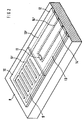
Das Stahlgehäuse 1 des in Fig. 1 schematisch dargestellten Gassensors ähnelt im Aufbau einer Pfeife. Es besitzt einen zwei gekrümmte Abschnitte und einen zylindrischen Mittelteil aufweisenden Strömungskanal, der die schlitzförmige Gaseintrittsöffnung 2 mit der ebenfalls schlitzförmigen Gasaustrittsöffnung 3 verbindet. Das planare Sensorelement 4 ist in Strömungsrichtung gesehen hinter einem Metallsteg 5 angeordnet und in einer nicht dargestellten Bohrung des Gehäuses 1 befestigt. Da der Abstand zwischen dem Steg 5 und dem Sensorelement 4 nur wenige Millimeter beträgt, können sich im Zwischenraum keine Wirbel ausbilden. Im Mittelteil des Kanals strömt das Meßgas daher weitgehend laminar und parallel zur Oberfläche der gasempfindlichen Metalloxidschicht 6. Um die Strömung auch im hinteren Teil des Kanals wirbelfrei zu halten, ist der in die Gasaustrittsöffnung 3 mündende Endabschnitt gekrümmt ausgeführt. Hier erfährt der Gasstrom eine Ablenkung um annähernd 90°, so daß das aus dem Gehäuse 1 entweichende und das in das Gehäuse eintretende Meßgas in dieselbe Richtung strömen.The
Der in die Gaseintrittsöffnung 2 mündende Abschnitt des Kanals ist ebenfalls gekrümmt und lenkt den Gasstrom um annähernd 90° in Richtung des Sensorelements 4 um. Da die im Meßgas vorhandenen schwereren Teilchen der Kanalkrümmung aufgrund ihrer Trägheit nicht folgen können, treffen sie im Bereich 7 auf die Kanalwand und bleiben dort haften. Die im abgelenkten Gasstrom eventuell noch mitgeführten leichteren Teilchen prallen auf den in Strömungsrichtung unmittelbar vor dem Sensor 4 angeordneten Metallsteg 5 bzw. werden aufgrund der sich hinter dem Steg 5 ausbildenden Gasströmung parallel am Sensorelement 4 vorbeigeführt.The section of the channel opening into the gas inlet opening 2 is also curved and deflects the gas flow by approximately 90 ° in the direction of the sensor element 4. Since the heavier particles present in the measuring gas cannot follow the channel curvature due to their inertia, they hit the channel wall in area 7 and adhere there. The lighter particles which may still be entrained in the deflected gas flow collide with the metal web 5 arranged directly in front of the sensor 4 in the direction of flow or are guided parallel to the sensor element 4 due to the gas flow forming behind the web 5.
Um eine weitgehend wirbelfreie Umströmung des Sensorelements 4 zu gewährleisten, sollte dieses einen planaren Aufbau besitzen und in der in Fig. 1 dargestellten Weise bezüglich des Steges ausgerichtet sein. Das Meßgas strömt insbesondere dann parallel zur gassensitiven Schicht 6, wenn die Stirnflächen des Steges 5 und des Sensorelements 4 annähernd dieselbe Größe aufweisen und der Steg 5 als ein sich in Strömungsrichtung verjüngender Körper ausgeführt ist.In order to ensure a largely vortex-free flow around the sensor element 4, it should have a planar structure and be oriented with respect to the web in the manner shown in FIG. 1. The measuring gas then flows in particular parallel to the gas-
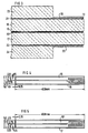
Der in Fig. 2 schematisch dargestellte Sensorelement zur Messung des Partialdrucks von Sauerstoff ähnelt im Aufbau den aus der EP-A-0 464 243 und 0 464 244 bekannten Detektoren. Er besitzt ein beispielsweise aus Magnesium-, Silizium- oder Aluminiumoxid bestehendes Substrat 8, auf dessen Oberfläche zwei eine Interdigitalstruktur bildende Platinelektroden 9 und 9', eine diese Elektroden bedeckende und etwa 1 bis 2 µm dicke Strontium- oder Bariumtitanatschicht 10 sowie ein Temperaturfühler 11 angeordnet sind. Die mit 12 bezeichnete Passivierungsschicht aus Glas oder Siliziumoxid schirmt die den Elektroden 9 und 9' und dem Temperaturfühler 11 jeweils zugeordneten Anschlußleitungen 13 und 13' bzw. 14 und 14' von dem im Meßgas vorhandenen Sauerstoff ab. Als Heizelement findet eine auf der Rückseite des Substrats 8 angeordnete Widerstandsschicht aus Platin Verwendung, die beispielsweise die in den Figuren 4 oder 5 dargestellte Struktur aufweisen kann.The sensor element shown schematically in FIG. 2 for measuring the partial pressure of oxygen is similar in construction to the detectors known from EP-A-0 464 243 and 0 464 244. It has a
Die Fig. 3 zeigt einen Schnitt durch den Kopf eines für den Einbau in das Pfeifengehäuse 1 besonders geeigneten Sensorelements. Bei dieser Ausführungsform dienen die mit 15 bzw. 15' bezeichneten und in den Figuren 4 und 5 dargestellten Platinschichten als Heizelement. Sie werden mittels eines Siebdruckverfahrens auf die Al₂O₃-Substrate 16 und 17 aufgebracht. Auf den den Platinschichten 15 und 15' jeweils gegenüberliegenden Flächen der Substrate 16 bzw. 17 sind die sauerstoffsensitive SrTiO₃ oder BaTiO₃-Schicht 18 und die Interdigitalelektroden 19 bzw. der ebenfalls aus Platin bestehende Temperatursensor 20 sowie deren Anschlußelektroden 21 bzw. 22 angeordnet. Vorteilhafte Geometrien für die das aufgesputterte Metalloxid 18 kontaktierenden Elektroden 19 und den Temperatursensor 20 finden sich in den Figuren 6 und 7 bzw. 8 und 9, wobei die Figuren 6 und 8 jeweils die Elektrodenstruktur im Bereich des Sensorkopfes zeigen. Die in Fig. 3 mit 23 und 24 bezeichneten Al₂O₃-Schichten sollen die den Interdigitalelektroden 19 und dem Temperatursensor 20 jeweils zugeordneten Anschlußleitungen 21 bzw. 22 vom Sauerstoff des den Sensor umströmenden Meßgases abschirmen.3 shows a section through the head of a sensor element that is particularly suitable for installation in the
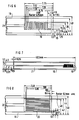
Das in Fig. 10 dargestellte Sensorgehäuse besteht aus zwei Teilen 25/26, wobei der beispielsweise aus Inconel gefertigte und die Gaseintrittsöffnung 27 und den Steg 28 enthaltende Gehäusekopf 25 auf dem mit einer Bohrung 29 zur Aufnahme des Sensorelements ausgestatteten Grundkörper 26 befestigt ist. Vor dem Verschweißen der beiden in den Figuren 11 und 12 im Schnitt dargestellten Teilen 25 und 26 wird das an den Außenflächen mit einem Keramikkleber bestrichene Sensorelement in die Bohrungen 29 des Grundkörpers 26 geschoben. Hierbei ist darauf zu achten, daß im Bereich des Sensorkopfes keine Verunreinigungen durch den Keramikkleber auftreten und die Klebestellen formgleich mit den Rundungen des Gehäusekopfes 25 abschließen. Die Aushärtung des Keramikklebers erfolgt während eines etwa 20 Minuten dauernden Tempervorgangs bei 200 °C.The sensor housing shown in FIG. 10 consists of two
Fig. 13 zeigt den fertig montierten Gassensor. Dargestellt ist auch die Keramik-(Makor-)-Platte 30, die die verklebte Bohrung 29 des unteren Gehäuseteils 26 abschließt (s. auch Fig. 14). Sie enthält insgesamt acht Durchführungen, durch die man die zur Kontaktierung des Sensorelements 31 erforderlichen Platindrähte 32 nach außen führt.13 shows the fully assembled gas sensor. Also shown is the ceramic (Makor)
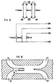
Um die Anzahl der elektrischen Anschlüsse von acht auf vier zu verringern, werden die Massen des Sensorelements, des Temperatursensors und der beiden Heizelemente in einem Anschluß 400 zusammengefaßt (s. Fig. 15). Während die Heizspannung zwischen den Anschlüssen 200 und 400 anliegt, kann man das den Sauerstoffpartialdruck repräsentierende Sensorsignal zwischen den Anschlüssen 100 und 400 und den Widerstand des Temperatursensors zwischen den Anschlüssen 300 und 400 abgreifen. Zur Isolation der Platindrähte werden diese beispielsweise in eine Glaskeramik aus Silizium-, Magnesium- oder Boroxiden eingeschmolzen.In order to reduce the number of electrical connections from eight to four, the masses of the sensor element, the temperature sensor and the two heating elements are combined in one connection 400 (see FIG. 15). While the heating voltage is present between the
Die Erfindung ist selbstverständlich nicht auf die beschriebenen Ausführungsbeispiele beschränkt. So ist es ohne weiteres möglich, mehrere, vorzugsweise symmetrisch zur Längsachse des Sensorgehäuses angeordnete Gaseintritts- und Gasaustrittsöffnungen 33, 33' bzw. 34, 34' vorzusehen und diese durch gekrümmte Seitenkanäle mit dem das Sensorelement 35 aufnehmenden Hauptkanal zu verbinden (s. Fig. 16).The invention is of course not limited to the exemplary embodiments described. It is thus readily possible to provide a plurality of gas inlet and
Auch ohne Verwendung eines Steges ist das Sensorelement sehr gut gegen Ablagerungen geschützt. Aufgrund der weitgehend wirbelfreien Strömung im Kanal besitzen die im umgelenkten Meßgas noch mitgeführten leichteren Teilchen keine oder nur eine sehr kleine transversale Geschwindigkeitskomponente in Richtung der sensitiven Schicht. Sie werden daher sehr schnell am Sensorelement vorbeigeführt und mit dem Meßgas aus dem Gehäuse transportiert. Eine in bekannten Systemen häufig beobachtete Ansammlung von Teilchen im Gehäuseinnern kann nicht stattfinden.Even without using a web, the sensor element is very well protected against deposits. Because of the largely vortex-free flow in the channel, the lighter particles still carried in the deflected measuring gas have no or only a very small transverse velocity component in the direction of the sensitive layer. They are therefore very quickly guided past the sensor element and transported out of the housing with the sample gas. An accumulation of particles frequently observed in known systems inside the housing cannot take place.
Das oben beschriebene Prinzip des Schutzes eines Sensorelements vor den in einem Gasstrom mitgeführten Teilchen läßt sich selbstverständlich auch bei Flüssigkeiten anwenden.The principle described above of protecting a sensor element from the particles carried in a gas stream can of course also be applied to liquids.
Claims (14)
dadurch gekennzeichnet,
characterized,
dadurch gekennzeichnet,
daß der Strömungskanal s-förmig gekrümmt ist.Sensor according to claim 1,
characterized,
that the flow channel is curved in an S-shape.
dadurch gekennzeichnet,
daß der Strömungskanal einen in die Eintrittsöffnung (2) mündenden ersten Abschnitt und einen in die Austrittsöffnung (3) mundenden zweiten Abschnitt aufweist und daß das Sensorelement (4) in einem den jeweils gekrümmten ersten und zweiten Kabelabschnitt verbindenden Mittelteil angeordnet ist.Sensor according to claim 1 or 2,
characterized,
that the flow channel has a first section opening into the inlet opening (2) and a second section opening into the outlet opening (3) and that the sensor element (4) is arranged in a central part connecting the respectively curved first and second cable sections.
dadurch gekennzeichnet,
daß der erste und/oder der zweite Abschnitt des Strömungskanals jeweils eine Krümmung von etwa 90° aufweisen.Sensor according to claim 3,
characterized,
that the first and / or the second section of the flow channel each have a curvature of approximately 90 °.
dadurch gekennzeichnet,
daß das den den ersten und den zweiten Kanalabschnitt verbindende Mittelteil einen kreisförmigen Querschnitt aufweist.Sensor according to claim 3 or 4,
characterized,
that the middle part connecting the first and the second channel section has a circular cross section.
dadurch gekennzeichnet,
daß das Sensorelement (4) in einem weitgehend laminar durchströmten Bereich des Strömungskanals angeordnet ist.Sensor according to one of claims 1 to 5,
characterized,
that the sensor element (4) is arranged in a largely laminar flow area of the flow channel.
dadurch gekennzeichnet,
daß das eine planare Struktur aufweisende Sensorelement (4) derart ausgerichtet ist, daß das Medium Parallel zur Oberfläche des Sensorelements (4) strömt.Sensor according to one of claims 1 to 6,
characterized,
that the sensor element (4) having a planar structure is oriented such that the medium flows parallel to the surface of the sensor element (4).
gekennzeichnet durch
eine in Strömungsrichtung unmittelbar vor dem Sensorelement (4) angeordnete Abschirmung (5).Sensor according to one of claims 1 to 7,
marked by
a shield (5) arranged directly in front of the sensor element (4) in the flow direction.
dadurch gekennzeichnet,
daß die vom Medium angeströmten Stirnflächen der Abschirmung (5) und des Sensorelements (4) annähernd gleich groß sind.Sensor according to claim 8,
characterized,
that the end faces of the shield (5) and the sensor element (4) that are flowed from the medium are approximately the same size.
dadurch gekennzeichnet,
daß die Abschirmung (5) sich in Strömungsrichtung verjüngt.Sensor according to claim 7 or 8,
characterized,
that the shield (5) tapers in the direction of flow.
dadurch gekennzeichnet,
daß das Gehäuse (1) aus einem oberen und einem unteren Teil besteht, wobei der obere Teil die Eintrittsöffnung (2), den ersten Abschnitt des Strömungskanals und ggf. die Abschirmung (5) enthält und das Sensorelement (4) am unteren Teil des Gehäuses befestigt ist.Sensor according to one of claims 1 to 10,
characterized,
that the housing (1) consists of an upper and a lower part, the upper part containing the inlet opening (2), the first section of the flow channel and possibly the shield (5) and the sensor element (4) on the lower part of the housing is attached.
dadurch gekennzeichnet,
daß die Eintritts- und die Austrittsöffnung (2, 3) jeweils schlitzförmig ausgebildet sind.Sensor according to one of claims 1 to 11,
characterized,
that the inlet and outlet openings (2, 3) are each slit-shaped.
dadurch gekennzeichnet,
daß das Gehäuse (1) mehrere jeweils in den Strömungskanal mündende Eintritts- und Austrittsöffnungen (33, 33', 34, 34') besitzt.Sensor according to one of claims 1 to 12,
characterized,
that the housing (1) has a plurality of inlet and outlet openings (33, 33 ', 34, 34') each opening into the flow channel.
Applications Claiming Priority (2)
| Application Number | Priority Date | Filing Date | Title |
|---|---|---|---|
| DE4324659 | 1993-07-22 | ||
| DE4324659A DE4324659C1 (en) | 1993-07-22 | 1993-07-22 | Sensor with a sensor element arranged in a housing |
Publications (2)
| Publication Number | Publication Date |
|---|---|
| EP0635717A2 true EP0635717A2 (en) | 1995-01-25 |
| EP0635717A3 EP0635717A3 (en) | 1995-04-26 |
Family
ID=6493473
Family Applications (1)
| Application Number | Title | Priority Date | Filing Date |
|---|---|---|---|
| EP94110903A Withdrawn EP0635717A3 (en) | 1993-07-22 | 1994-07-13 | Sensor with a sensor element situated in a casing. |
Country Status (4)
| Country | Link |
|---|---|
| US (1) | US5505073A (en) |
| EP (1) | EP0635717A3 (en) |
| JP (1) | JPH07151723A (en) |
| DE (1) | DE4324659C1 (en) |
Cited By (3)
| Publication number | Priority date | Publication date | Assignee | Title |
|---|---|---|---|---|
| US6109094A (en) * | 1994-09-23 | 2000-08-29 | Forskarpatent I Linkoping Ab | Method and device for gas sensing |
| WO2007062969A1 (en) * | 2005-12-02 | 2007-06-07 | Robert Bosch Gmbh | Sensor element for a gas sensor having a resistance heater |
| WO2009045448A3 (en) * | 2007-10-01 | 2009-05-22 | Scott Tech Inc | Gas measuring device and method of manufacturing the same |
Families Citing this family (35)
| Publication number | Priority date | Publication date | Assignee | Title |
|---|---|---|---|---|
| DE19523978C2 (en) * | 1995-06-30 | 1998-05-20 | Siemens Ag | Exhaust gas sensor with low response time |
| US5689059A (en) * | 1996-08-14 | 1997-11-18 | Motorola, Inc. | Selective gas sensor |
| US6026639A (en) | 1997-11-03 | 2000-02-22 | Engelhard Corporation | Apparatus and method for diagnosis of catalyst performance |
| US6071476A (en) * | 1997-11-14 | 2000-06-06 | Motorola, Inc. | Exhaust gas sensor |
| US6015533A (en) * | 1997-11-14 | 2000-01-18 | Motorola Inc. | Sensor housing for a calorimetric gas sensor |
| US5989398A (en) * | 1997-11-14 | 1999-11-23 | Motorola, Inc. | Calorimetric hydrocarbon gas sensor |
| US6322247B1 (en) * | 1999-01-28 | 2001-11-27 | Honeywell International Inc. | Microsensor housing |
| US6361206B1 (en) | 1999-01-28 | 2002-03-26 | Honeywell International Inc. | Microsensor housing |
| DE19916797C2 (en) * | 1999-04-14 | 2001-08-16 | Daimler Chrysler Ag | Semiconductor gas sensor with housing and method for measuring gas concentrations |
| DE19957991C2 (en) * | 1999-12-02 | 2002-01-31 | Daimler Chrysler Ag | Arrangement of a heating layer for a high temperature gas sensor |
| DE10011562C2 (en) * | 2000-03-09 | 2003-05-22 | Daimler Chrysler Ag | gas sensor |
| US6773678B2 (en) | 2000-03-20 | 2004-08-10 | Endress + Hauser Conducta Gesellschaft Fur Mess Und Regeltechnik Mbh + Co. | Mounting system and retractable sensor holder for analytical sensors |
| DE60116771T2 (en) * | 2000-06-28 | 2006-11-02 | The Government Of The United States Of America, As Represented By The Secretary Of The Navy Naval Research Laboratory | APPARATUS AND METHOD FOR PNEUMATIC SAMPLING FOR GAS SENSORS |
| DE10131581B4 (en) * | 2000-09-12 | 2008-04-03 | Robert Bosch Gmbh | Method and device for generating and checking composite arrangements |
| DE10163760C5 (en) * | 2001-12-28 | 2012-02-02 | Ebro Electronic Gmbh & Co. Kg | Apparatus and method for measuring the condition of oils and fats |
| US20030131552A1 (en) * | 2002-01-15 | 2003-07-17 | Franz Leichtfried | Siding system |
| DE10253970A1 (en) * | 2002-11-20 | 2004-06-03 | Robert Bosch Gmbh | Device for determining at least one parameter of a medium flowing in a line |
| GB2400178A (en) * | 2003-03-29 | 2004-10-06 | Rolls Royce Plc | A combustion sensor arrangement |
| US8088333B2 (en) * | 2003-04-28 | 2012-01-03 | Invoy Technology, LLC | Thermoelectric sensor for analytes in a gas |
| EP1627218A2 (en) * | 2003-04-28 | 2006-02-22 | Arizona Board of Regents, acting for and on behalf of, Arizona State University | Thermoelectric biosensor for analytes in a gas |
| US8722417B2 (en) | 2003-04-28 | 2014-05-13 | Invoy Technologies, L.L.C. | Thermoelectric sensor for analytes in a fluid and related method |
| US20080053193A1 (en) * | 2003-04-28 | 2008-03-06 | Ahmad Lubna M | Thermoelectric sensor for analytes in a gas and related method |
| US20080053194A1 (en) * | 2003-04-28 | 2008-03-06 | Ahmad Lubna M | Thermoelectric sensor for analytes in a gas and related method |
| DE102004013853A1 (en) * | 2004-03-20 | 2005-10-06 | Robert Bosch Gmbh | Sensor for determining a physical property of a sample gas |
| DE102008009206A1 (en) | 2008-02-15 | 2009-09-24 | Sensatronic Gmbh | Measuring device i.e. solid electrolytic gas sensor, for determining partial pressure of components contained in gas mixture, has sensor element arranged in measuring chamber and staying in contact with measuring gas by diffusion element |
| DE202008002332U1 (en) | 2008-02-20 | 2009-06-25 | Sensatronic Gmbh | measuring device |
| US7980132B2 (en) | 2008-08-26 | 2011-07-19 | Caterpillar Inc. | Sensor assembly having a thermally insulating enclosure |
| DE102009000318A1 (en) * | 2009-01-20 | 2010-07-22 | Robert Bosch Gmbh | particle sensor |
| DE102013204911B4 (en) * | 2013-03-20 | 2015-02-26 | Continental Automotive Gmbh | sensor device |
| JP6099094B2 (en) * | 2013-06-21 | 2017-03-22 | 日立オートモティブシステムズ株式会社 | Gas sensor device and gas sensor device mounting structure |
| CN103940581B (en) * | 2014-04-28 | 2016-03-23 | 上海理工大学 | A kind of experimental technique of monitoring trace gas concentration value measurement jet entrainment amount |
| DE102017112611A1 (en) * | 2017-06-08 | 2018-12-13 | Heraeus Noblelight Gmbh | Infrared radiator and method for its manufacture |
| JP2019148501A (en) * | 2018-02-27 | 2019-09-05 | 日本碍子株式会社 | Sensor for fluid |
| CN108844204A (en) * | 2018-06-19 | 2018-11-20 | 珠海格力电器股份有限公司 | Temperature Humidity Sensor protective device and air-conditioning line control machine with it |
| WO2020116034A1 (en) * | 2018-12-05 | 2020-06-11 | 日立オートモティブシステムズ株式会社 | Physical quantity measurement device |
Citations (3)
| Publication number | Priority date | Publication date | Assignee | Title |
|---|---|---|---|---|
| US4535316A (en) * | 1984-03-26 | 1985-08-13 | Allied Corporation | Heated titania oxygen sensor |
| EP0222987A2 (en) * | 1985-11-02 | 1987-05-27 | VDO Adolf Schindling AG | Arrangement comprising an air flow meter for an internal-combustion engine |
| EP0503295A1 (en) * | 1991-03-12 | 1992-09-16 | Siemens Aktiengesellschaft | Protective cover for exhaust gas sensors |
Family Cites Families (14)
| Publication number | Priority date | Publication date | Assignee | Title |
|---|---|---|---|---|
| GB862147A (en) * | 1956-05-23 | 1961-03-01 | Ass Elect Ind | Improvements in and relating to apparatus for smoke detection |
| DE2063963A1 (en) * | 1970-12-28 | 1972-07-20 | Bosch Gmbh Robert | Fuel injection system for mixture-compressing, spark-ignited internal combustion engines |
| US4115229A (en) * | 1976-11-08 | 1978-09-19 | Thermo-Lab Instruments, Inc. | Apparatus for sampling a gaseous stream |
| US4339318A (en) * | 1979-12-27 | 1982-07-13 | Fuji Electric Co., Ltd. | Oxygen gas analyzing device |
| US4492614A (en) * | 1983-07-08 | 1985-01-08 | Uop Inc. | Chlorine detection |
| DE3588143T2 (en) * | 1984-04-02 | 1997-06-12 | Hitachi Ltd | Oxygen sensor |
| US4571996A (en) * | 1984-08-10 | 1986-02-25 | Allied Corporation | Air flow sensor |
| DE3500088A1 (en) * | 1985-01-03 | 1986-07-03 | Uop Inc | Method and device for detecting chlorine |
| DE3743295C1 (en) * | 1987-12-19 | 1988-07-07 | Daimler Benz Ag | Device for prolonging the service life and improving the measurement presence of a lambda probe installed in the exhaust gas flow of an internal combustion engine |
| JPH01169350A (en) * | 1987-12-25 | 1989-07-04 | Ngk Insulators Ltd | Oxygen sensor |
| JP2607614B2 (en) * | 1988-04-20 | 1997-05-07 | 電気化学計器株式会社 | Cell for measuring components in gas |
| US4944861A (en) * | 1989-04-03 | 1990-07-31 | Barber-Colman Company | Oxygen sensing probe having improved sensor tip and tip-supporting tube |
| ATE123877T1 (en) * | 1990-07-04 | 1995-06-15 | Siemens Ag | SENSOR FOR DETECTING REDUCING GASES. |
| EP0464243B1 (en) * | 1990-07-04 | 1995-06-14 | Siemens Aktiengesellschaft | Oxygen sensor with semiconducting gallium oxide |
-
1993
- 1993-07-22 DE DE4324659A patent/DE4324659C1/en not_active Expired - Fee Related
-
1994
- 1994-07-13 EP EP94110903A patent/EP0635717A3/en not_active Withdrawn
- 1994-07-21 JP JP6190161A patent/JPH07151723A/en not_active Withdrawn
- 1994-07-22 US US08/279,038 patent/US5505073A/en not_active Expired - Fee Related
Patent Citations (3)
| Publication number | Priority date | Publication date | Assignee | Title |
|---|---|---|---|---|
| US4535316A (en) * | 1984-03-26 | 1985-08-13 | Allied Corporation | Heated titania oxygen sensor |
| EP0222987A2 (en) * | 1985-11-02 | 1987-05-27 | VDO Adolf Schindling AG | Arrangement comprising an air flow meter for an internal-combustion engine |
| EP0503295A1 (en) * | 1991-03-12 | 1992-09-16 | Siemens Aktiengesellschaft | Protective cover for exhaust gas sensors |
Cited By (3)
| Publication number | Priority date | Publication date | Assignee | Title |
|---|---|---|---|---|
| US6109094A (en) * | 1994-09-23 | 2000-08-29 | Forskarpatent I Linkoping Ab | Method and device for gas sensing |
| WO2007062969A1 (en) * | 2005-12-02 | 2007-06-07 | Robert Bosch Gmbh | Sensor element for a gas sensor having a resistance heater |
| WO2009045448A3 (en) * | 2007-10-01 | 2009-05-22 | Scott Tech Inc | Gas measuring device and method of manufacturing the same |
Also Published As
| Publication number | Publication date |
|---|---|
| US5505073A (en) | 1996-04-09 |
| EP0635717A3 (en) | 1995-04-26 |
| DE4324659C1 (en) | 1995-04-06 |
| JPH07151723A (en) | 1995-06-16 |
Similar Documents
| Publication | Publication Date | Title |
|---|---|---|
| EP0635717A2 (en) | Sensor with a sensor element situated in a casing | |
| EP1896838B1 (en) | Sensor and operating method for detecting soot | |
| DE2937048C2 (en) | Electrochemical measuring sensor for determining the oxygen content in gases, especially in exhaust gases from internal combustion engines | |
| DE2804850C2 (en) | Device for measuring the flow rate of gases | |
| DE2937105A1 (en) | PROTECTIVE SHIELD FOR A SENSOR ELEMENT | |
| DE2937089A1 (en) | PROTECTIVE SHIELD FOR A SENSOR | |
| DE2748461A1 (en) | DEVICE FOR MEASURING THE PARTIAL OXYGEN PRESSURE | |
| EP1941244A1 (en) | Flow sensor element and its self-cleaning | |
| DE102005015103A1 (en) | Particle sensor and method of operating the same | |
| EP2035786A2 (en) | Sheet resistor in an exhaust pipe | |
| EP2251651A2 (en) | Mounting arrangement of a metal film resistor of an anemometric measuring device within an exhaust gas conduit | |
| EP0193015A2 (en) | Probe for measuring electrical conductivity | |
| DE19549147A1 (en) | Gas sensor | |
| DE4432749A1 (en) | Oxygen-concentration detector and method for its production | |
| DE4009890A1 (en) | MEASURING PROBE FOR DETERMINING THE OXYGEN CONTENT IN GASES | |
| DE102004043122A1 (en) | Sensor element for particle sensors and method for producing the same | |
| DE10156946A1 (en) | Sensor used for detecting soot particles in exhaust gas stream, comprises measuring electrodes arranged on substrate consisting of solid body electrolyte containing oxygen pump cells to which electrode pair is assigned | |
| EP2035785A1 (en) | Measuring apparatus for measuring the flow rate of a combustion gas mixture, comprising a correction device | |
| DE4020601C2 (en) | Flow meter | |
| DE102004038988B3 (en) | Gas mass flow measurement system for various applications has substrate with ceramic particles in organic matrix holding heating elements with temperature sensors | |
| DE19523978C2 (en) | Exhaust gas sensor with low response time | |
| DE102006032549A1 (en) | Sensor element for determining gas component or particles, comprises carrier body with through hole , where sensitive area of sensor element is arranged as ceramic membrane in through hole and has measuring electrodes | |
| DE19543537C2 (en) | Exhaust gas sensor and circuit arrangement for the exhaust gas sensor | |
| DE2104767B2 (en) | Differential refractometer | |
| DE10233362A1 (en) | Device for determining the exhaust gas recirculation rate of an internal combustion engine |
Legal Events
| Date | Code | Title | Description |
|---|---|---|---|
| PUAI | Public reference made under article 153(3) epc to a published international application that has entered the european phase |
Free format text: ORIGINAL CODE: 0009012 |
|
| AK | Designated contracting states |
Kind code of ref document: A2 Designated state(s): DE ES FR GB SE |
|
| PUAL | Search report despatched |
Free format text: ORIGINAL CODE: 0009013 |
|
| AK | Designated contracting states |
Kind code of ref document: A3 Designated state(s): DE ES FR GB SE |
|
| 17P | Request for examination filed |
Effective date: 19950621 |
|
| STAA | Information on the status of an ep patent application or granted ep patent |
Free format text: STATUS: THE APPLICATION IS DEEMED TO BE WITHDRAWN |
|
| 18D | Application deemed to be withdrawn |
Effective date: 19970201 |