EP0638832A2 - Liquid crystal display apparatus - Google Patents
Liquid crystal display apparatus Download PDFInfo
- Publication number
- EP0638832A2 EP0638832A2 EP94112453A EP94112453A EP0638832A2 EP 0638832 A2 EP0638832 A2 EP 0638832A2 EP 94112453 A EP94112453 A EP 94112453A EP 94112453 A EP94112453 A EP 94112453A EP 0638832 A2 EP0638832 A2 EP 0638832A2
- Authority
- EP
- European Patent Office
- Prior art keywords
- liquid crystal
- crystal panel
- backlight
- housing
- disposed
- Prior art date
- Legal status (The legal status is an assumption and is not a legal conclusion. Google has not performed a legal analysis and makes no representation as to the accuracy of the status listed.)
- Granted
Links
Images


Classifications
-
- G—PHYSICS
- G02—OPTICS
- G02F—OPTICAL DEVICES OR ARRANGEMENTS FOR THE CONTROL OF LIGHT BY MODIFICATION OF THE OPTICAL PROPERTIES OF THE MEDIA OF THE ELEMENTS INVOLVED THEREIN; NON-LINEAR OPTICS; FREQUENCY-CHANGING OF LIGHT; OPTICAL LOGIC ELEMENTS; OPTICAL ANALOGUE/DIGITAL CONVERTERS
- G02F1/00—Devices or arrangements for the control of the intensity, colour, phase, polarisation or direction of light arriving from an independent light source, e.g. switching, gating or modulating; Non-linear optics
- G02F1/01—Devices or arrangements for the control of the intensity, colour, phase, polarisation or direction of light arriving from an independent light source, e.g. switching, gating or modulating; Non-linear optics for the control of the intensity, phase, polarisation or colour
- G02F1/13—Devices or arrangements for the control of the intensity, colour, phase, polarisation or direction of light arriving from an independent light source, e.g. switching, gating or modulating; Non-linear optics for the control of the intensity, phase, polarisation or colour based on liquid crystals, e.g. single liquid crystal display cells
- G02F1/133—Constructional arrangements; Operation of liquid crystal cells; Circuit arrangements
- G02F1/1333—Constructional arrangements; Manufacturing methods
- G02F1/133308—Support structures for LCD panels, e.g. frames or bezels
-
- G—PHYSICS
- G02—OPTICS
- G02F—OPTICAL DEVICES OR ARRANGEMENTS FOR THE CONTROL OF LIGHT BY MODIFICATION OF THE OPTICAL PROPERTIES OF THE MEDIA OF THE ELEMENTS INVOLVED THEREIN; NON-LINEAR OPTICS; FREQUENCY-CHANGING OF LIGHT; OPTICAL LOGIC ELEMENTS; OPTICAL ANALOGUE/DIGITAL CONVERTERS
- G02F1/00—Devices or arrangements for the control of the intensity, colour, phase, polarisation or direction of light arriving from an independent light source, e.g. switching, gating or modulating; Non-linear optics
- G02F1/01—Devices or arrangements for the control of the intensity, colour, phase, polarisation or direction of light arriving from an independent light source, e.g. switching, gating or modulating; Non-linear optics for the control of the intensity, phase, polarisation or colour
- G02F1/13—Devices or arrangements for the control of the intensity, colour, phase, polarisation or direction of light arriving from an independent light source, e.g. switching, gating or modulating; Non-linear optics for the control of the intensity, phase, polarisation or colour based on liquid crystals, e.g. single liquid crystal display cells
- G02F1/133—Constructional arrangements; Operation of liquid crystal cells; Circuit arrangements
- G02F1/1333—Constructional arrangements; Manufacturing methods
- G02F1/1335—Structural association of cells with optical devices, e.g. polarisers or reflectors
- G02F1/1336—Illuminating devices
- G02F1/133602—Direct backlight
- G02F1/133604—Direct backlight with lamps
-
- G—PHYSICS
- G02—OPTICS
- G02F—OPTICAL DEVICES OR ARRANGEMENTS FOR THE CONTROL OF LIGHT BY MODIFICATION OF THE OPTICAL PROPERTIES OF THE MEDIA OF THE ELEMENTS INVOLVED THEREIN; NON-LINEAR OPTICS; FREQUENCY-CHANGING OF LIGHT; OPTICAL LOGIC ELEMENTS; OPTICAL ANALOGUE/DIGITAL CONVERTERS
- G02F2201/00—Constructional arrangements not provided for in groups G02F1/00 - G02F7/00
- G02F2201/50—Protective arrangements
- G02F2201/503—Arrangements improving the resistance to shock
Definitions
- the present invention relates to a liquid crystal display apparatus.
- the liquid crystal display apparatus includes a liquid crystal panel 101 and a backlight device 100B, respectively housed in a cover 110.
- the liquid crystal panel 101 comprises a pair of glass substrates 101a and 101b sandwiching a liquid crystal.
- the two glass substrates 101a and 101b are respectively provided with transparent electrodes at their inner surfaces.
- Polarizers 107 and 108 are applied onto both sides of the liquid crystal panel 101.
- a flexible printed wire film (“TAB film”) 103 loaded with a drive IC is connected, and a peripheral circuit plate 102 of a drive IC for driving the liquid crystal panel 101 is connected to the TAB film 103.
- TAB film flexible printed wire film
- the backlight device 100B includes fluorescent lamps 104, a reflection plate 105 and a diffusion plate 106 so that a light flux from a fluorescent lamps 104 is reflected by the reflection plate 105, diffused by the diffusion plate 106 and then cast at a uniform luminance onto the liquid crystal panel 101.
- the liquid crystal panel 101 is fixed onto the cover 10 composed of a plate metal or a resin via a cushioning member 109 comprising, e.g., rubber.
- the cushioning member 109 is disposed between the liquid crystal panel 101 and the cover 110, and a vibration or impact applied to the cover 110 is transmitted to the liquid crystal panel 101 without substantial attenuation, so that the liquid crystal panel 101 receiving a mechanical stress is liable to cause a degradation in display quality.
- the liquid crystal injected into the liquid crystal panel 101 may be a nematic liquid crystal or a ferroelectric liquid crystal, of which the ferroelectric liquid crystal is weaker against a mechanical stress compared with the nematic liquid crystal. Accordingly, the above difficulty is particularly pronounced in the liquid crystal display apparatus using a ferroelectric liquid crystal.
- cushioning members for supporting a liquid crystal panel 101 are disposed in two layers, and an almost closed space 100A1 is formed below the liquid crystal panel 101 so as to cause an air damper effect (details of which will be described later), thereby increasing the performances of attenuating the vibration and/or impact.
- the liquid crystal display apparatus shown in Figure 2 is equipped with a fixing plate 112 which is provided with an opening 112a and remains like a picture frame.
- the liquid crystal panel 101 having a structure described above is applied onto the fixing plate 112 with an elastic adhesive applied at all the peripheral part surrounding the opening 112a, whereby the opening 112a is stopped by the liquid crystal panel 101.
- the above-mentioned peripheral circuit plate 102 is fixed onto the fixing plate 112.
- a frame member 114 Surrounding the fixing plate 112, a frame member 114 is disposed with a prescribed spacing, and the fixing plate 112 is supported in the form of being hanged in space with the frame member 114 via an elastic resin 115.
- a frame-shaped fixing plate 115 provided with a central opening is fixed, and the opening of the fixing plate 115 is stopped with a protective plate comprising a transparent sheet like that of glass.
- a polarizer 118 is applied on the lower side of the protective plate 111.
- a backlight device 100B is affixed, and an almost closed space 100A1 is defined by the backlight device 100B, the liquid crystal panel 101, the fixing plate 112, etc.
- a polarizer applied onto a transparent sheet of glass, etc. is disposed on the upper surface of the diffusion plate 106.
- the vibration, etc. is attenuated by the resin 115 and adhesive 113 and not substantially transmitted to the liquid crystal panel 101. Further, even if the liquid crystal panel 101 is vibrated to some extent, the vibration is quickly attenuated by the air damper effect due to air within the almost closed space 100A1. More specifically, when the liquid crystal panel 101 is vibrated, the space 100A1 causes repetitive contraction and expansion, the contraction and expansion function as a resistance to the vibration of the liquid crystal panel 101 due to the almost closed state of the space 100A1, so that the vibration is quickly attenuated while receiving a cushioning effect of the space 100A1. In this way, the liquid crystal panel 101 is protected from a mechanical stress and is thus free from a deterioration in display quality due to such a mechanical stress.
- FIG 4 shows another example of known liquid crystal display apparatus.
- the liquid crystal display apparatus includes a liquid crystal panel 203 comprising a liquid crystal disposed between a pair of substrates 215 and 216 each provided with electrodes.
- the liquid crystal panel 203 is provided with polarizing films 201 and 202 applied onto both sides thereof and also has a function of a polarizer.
- a flexible printed wire film (“TAB film”) 204 loaded with a drive IC is connected to a side of the liquid crystal panel 101, and a peripheral circuit plate 102 for a drive IC for driving the liquid crystal panel 203 is connected to the TAB film 204.
- TAB film flexible printed wire film
- the liquid crystal display apparatus is equipped with a panel-fixing plate 206, and the panel-fixing plate 206 is provided with an opening 217.
- an elastomeric adhesive 207 is applied so as to fix the liquid crystal panel 203 onto the panel-fixing plate, so that the liquid crystal panel 203 stops the opening 217.
- the panel-fixing plate 206 is supported in the form of being hanged in space by a fixing plate-supporting member 209 via an elastic member 208 and, to the lower part of the fixing plate-supporting member 209, a backlight unit 211 is affixed and, below the liquid crystal panel 203, an almost closed space 200A is defined by the panel-fixing plate 206, the fixing plate-supporting member 209, the backlight unit 211, the adhesive 207 and the elastic member 208.
- the backlight unit 211 includes tubular lamps such as thermal cathode tubes (not shown) and a diffusion plate 212 above the lamps.
- the diffusion plate 212 is used to scatter and diffuse light from the lamps so that the scattered and diffused light is caused to illuminate the liquid crystal panel 203.
- the above-described backlight unit 211, liquid crystal panel 203, etc., are fixed to a housing 210 of the apparatus.
- the surface of the liquid crystal panel 203 (the lower surface of the polarizer film) is exposed, so that dust or dirt is liable to attach thereto.
- the attached dust etc. even if it is small enough to be not recognized by human eyes, can cause display defects, and a wiping operation required for removing the attached dust is not desirable as it applied an external force to the panel. Further, if the backlight unit is exchanged in a clean room so as to obviate the dust attachment, the operation becomes troublesome and impractical.
- the spacing d changes along with the vibration of the liquid crystal panel 203, so that it is necessary to increase the effective luminescent region L while taking the maximum value of the spacing d into consideration. As a result, there arises a difficulty that the backlight unit is enlarged in capacity.
- FIG 8 shows another example of known liquid crystal display apparatus including a liquid crystal panel and a backlight device supported integrally.
- the liquid crystal display apparatus 301 includes an upper housing 302 including an opening 302a and a transparent display plate (transparent part) 303 stopping the opening 302a.
- the inner side of the upper housing 302 is provided with bosses 302b, to the lower ends of which a panel-fixing member 305 is horizontally supported.
- the fixing member 305 is in the form of a picture frame surrounding a central opening.
- a liquid crystal panel 306 is applied with an adhesive 307 so as to stop the opening 305a.
- the liquid crystal panel 306 comprises two glass substrates 306a and 306b disposed opposite to each other so as to have transparent electrodes on their opposing sides, and a liquid crystal (not shown) disposed between the substrates 306a and 306b.
- the liquid crystal panel 306 has polarizing films (not shown) attached thereto on both sides.
- a TAB film 309 loaded with a drive IC is connected, and a peripheral circuit substrate 310 for the driver IC for driving the liquid crystal panel 306 (hereinafter called "driver board 310”) is connected to the TAB film 309.
- the driver board 310 is screwed to the fixing member 305.
- a backlight device 311 is affixed to the lower surface of the fixing member 305.
- the backlight device 311 includes fluorescent lamps, a reflection plate and a diffusion plate so as to illuminate the liquid crystal panel 306 at a uniform luminance.
- a lower housing 312 is detachably supported, and the liquid crystal panel 306, etc., are housed within the housing 302 and 312.
- a prescribed spacing d is provided between the display plate 303 (the lower surface of the upper housing 302) and the liquid crystal panel 306 so that the display plate 303 will not touch the liquid crystal panel 306 even when the display plate is deformed by receiving an external force.
- a region outside the display region 300A of the liquid crystal panel 306 should desirably be not seen from the outside because of an improved appearance and, for this purpose, a portion in the non-display region 303C of the lower surface of the display plate is provided with a printed frame 313 for light interception.
- a large spacing d between the display plate 303 (upper surface of the housing 302) and the liquid crystal panel 306 is not desirable because it gives an impression that the panel face is depressed inside. For this reason, it is a current practice to adopt a structure wherein the liquid crystal panel 306 is fixed on the upper surface of the fixing member 305 to provide a small spacing d as shown in Figure 9.
- Figure 11 shows another example of known liquid crystal display apparatus using a ferroelectric liquid crystal.
- the liquid crystal display apparatus 401 principally includes a liquid crystal cell 402, a fixing member (cell-supporting member) 403 for supporting the cell 402, and a backlight 405, which are supported by a fixing frame 406.
- the cell 402 comprises a ferroelectric liquid crystal sandwiched between a pair of glass substrates each having thereon transparent electrodes and supplied with an aligning treatment.
- the fixing plate 403 is composed of, e.g., a plastic or metal plate, and is provided with an opening which is a little smaller than the cell 402.
- a rubber-type adhesive 407 is applied, and the cell 402 is applied therewith so as to stop the opening.
- the cell 402 is provided with an upper polarizer 409 and a lower polarizer 410 applied onto both sides.
- a flexible printed wire film 411 is connected, and a circuit substrate 412 for driving the cell 402 is electrically connected to the printed wire film 411.
- the circuit substrate 412 is fixed to the fixing plate 402 with screws, etc.
- a unit including the fixing plate 403, the cell 402, the upper and lower polarizers 409 and 410, the printed wire film 411 and the circuit substrate is called a "display unit U”.
- the display unit U is supported in the form of being hanged in space by the fixing frame 406 as the whole periphery of the fixing plate 403 is applied with the rubber-type adhesive 413.
- the backlight 405 is affixed.
- a diffusion plate 408 is applied onto the surface of the backlight 405.
- An almost closed space 415 is defined by the backlight 405, the fixing frame 406, the fixing plate 403 and the cell 402, so that the vibration, if any, of the cell 403 is quickly attenuated due to the air damper effect of the almost closed space 415.
- a display plate 417 is affixed via a cover 416, so as to protect the cell 402, etc., thereby.
- a rubber-type adhesive 413 is disposed between the fixing frame 406 and the fixing plate 403, and a similar elastic rubber-type adhesive 407 is disposed between the fixing plate 403 and the cell 402, so that an external impact or vibration can be attenuated by the adhesives 413 and 407, and is not readily transmitted to the cell 402.
- the almost closed space 415 is formed by the backlight 405, the fixing frame 406, the fixing plate 403 and the cell 402, a slight degree of vibration, if any, of the cell 402 can be quickly attenuated by the air damper effect of the almost closed space 415.
- the warping of the cell 402 is suppressed to the minimum, whereby the occurrence of alignment defects and lowering in display quality peculiarly encountered with a ferroelectric liquid crystal cell can be suppressed.
- the display unit U is supported by a rubber-type adhesive disposed on the four sides of the display unit U. Accordingly, there can arise a problem that the rubber adhesive 413 can cause a lowering in elasticity due to deterioration in long term use, thus failing to provide a complete attenuation of vibration and resulting in alignment defects in the cell 402. This problem is not so conspicuous if the cell 402 is as small as at most 15 inches but is conspicuous if the cell is as large as 20 inches or larger.
- such a large size panel is generally used in an upright position as in a desktop word processor and, in such a case, the total weight of the display unit U is not dispersed to the entirety of the rubber-type adhesive but is concentrated at particular parts, at which the adhesive 413 is liable to cause an accelerated deterioration.
- a first object of the present invention is to provide a liquid crystal display apparatus capable of preventing dust attachment onto a liquid crystal panel and facilitating the exchange of a backlight by disposing a light-transmissive plate in the vicinity of the liquid crystal panel so as to form a first almost closed space capable of retaining the closed state thereof even during the exchange of the backlight.
- a second object of the present invention is to provide a liquid crystal display apparatus capable of preventing dust attachment onto a liquid crystal panel and reducing the size of a backlight by disposing a diffusion plate in the vicinity of a liquid crystal panel so as to define a closed space and retain the closed state of the space even during the exchange of the backlight.
- a third object of the present invention is to provide a liquid crystal display apparatus having an elastic member disposed at a gap between the periphery of a liquid crystal panel and an upper housing so as to provide an improved appearance, and also an information transmission apparatus including such a liquid crystal display apparatus.
- a fourth object of the present invention is to provide a ferroelectric liquid crystal display apparatus including a cell and a cell-supporting member supported in the form of being hanged in space with a spring so as to retain a vibration attenuation effect and allow air convection around the cell to suppress the temperature raise of the cell.
- a liquid crystal display apparatus comprising: a housing, a liquid crystal panel comprising a liquid crystal disposed between a pair of substrates each provided with electrodes, the liquid crystal panel being affixed to the housing, a backlight for illuminating the liquid crystal panel, detachably affixed to the housing, and a light-transmissive plate allowing transmission of light from the backlight, disposed between the liquid crystal panel and the backlight so as to define an almost closed first space in cooperation with the liquid crystal panel, the first space retaining its almost closed state even when the backlight is detached from the housing.
- liquid crystal panel and the housing in combination define an almost closed second space, and the first space and the second space are disposed to sandwich the liquid crystal panel.
- a part of the housing opposing the liquid crystal panel is formed of glass.
- the liquid crystal can be a ferroelectric liquid crystal.
- the light-transmissive plate disposed in the vicinity of the liquid crystal panel defines an almost closed first space, of which the closed state is retained even when the backlight is exchanged, whereby dust, etc., are prevented from being attached onto the liquid crystal panel on its side confronting the backlight.
- a liquid crystal display apparatus comprising: a liquid crystal panel comprising a liquid crystal disposed between a pair of substrates each provided with electrodes, a backlight for illuminating the liquid crystal panel, a diffusion plate disposed between the backlight and the liquid crystal panel for diffusing light from the backlight, and a housing supporting the liquid crystal panel, the backlight and the diffusion plate, wherein the diffusion plate is disposed in the vicinity of the liquid crystal panel so as to define an almost closed space in combination with the liquid crystal panel.
- a supporting member having an opening is supported via an elastic member by the housing in the form of being hanged in space, the liquid crystal panel is affixed to the supporting member so as to cover one side of the opening, and the diffusion plate is affixed to the supporting member so as to cover another side of the opening, so that the liquid crystal panel, the supporting member and the diffusion plate in combination define the above-mentioned almost closed space.
- the diffusion plate disposed in the vicinity of the liquid crystal panel defines a closed space in cooperation with the liquid crystal panel.
- the disposition of the diffusion plate close to the liquid crystal panel has a similar effect as the disposition of the backlight closer to the liquid crystal panel.
- a liquid crystal display apparatus comprising: a liquid crystal panel comprising a liquid crystal disposed between a pair of substrates each provided with electrodes, a housing disposed to house the liquid crystal panel and equipped with a transparent portion so as to allow observation of the liquid crystal panel therethrough, the transparent portion and the liquid crystal panel confronting each other with a prescribed distance therebetween, wherein a nontransparent elastic member is disposed between the housing and the liquid crystal panel so as to surround a display region of the liquid crystal panel.
- an information transmission apparatus comprising: a graphic controller for outputting a data signal and a scanning scheme signal, a scanning signal control circuit for outputting scanning line address data and a scanning scheme signal, and the above-mentioned liquid crystal display apparatus.
- a nontransparent elastic member is disposed between the housing and the liquid crystal panel so as to surround a display region of the liquid crystal panel, so that the interior (non-display region) of the liquid crystal display apparatus is made non-observable regardless of a gap formed between the transparent portion of the housing and the liquid crystal panel.
- a ferroelectric liquid crystal display apparatus comprising: a liquid crystal cell comprising a ferroelectric liquid crystal disposed between a pair of substrates each provided with electrodes, a cell-supporting member for supporting the cell, a fixing frame for supporting the cell-supporting member, and a spring member disposed between the fixing frame and the cell-supporting member for hanging the cell-supporting member and the cell in space.
- the spring member comprises a metallic bar formed in a coil or a hairpin. It is also possible that the spring member comprises a so-called plate spring or a metallic plate formed in a U-shaped or a hairpin. It is further possible that the spring member comprises a resin or a composite material of a resin and a metal.
- an external vibration or impact applied to the fixing frame is attenuated by the spring member and is not readily transmitted to the cell-supporting member or the cell.
- the spring member does not readily lower its elasticity even in a long term of use so that its function of attenuating the vibration can be retained.
- the spring member can be disposed between the fixing frame and the cell-supporting member without showing a space-sealing effect so that air convection is not hindered thereby.
- Figures 1, 2, 4 and 8 are sectional views each showing a structure of a known liquid crystal display apparatus.
- Figures 3 and 6 are sectional views illustrating the states of exchanging backlight devices in the apparatus of Figures 2 and 4, respectively.
- Figure 5 is a sectional view illustrating the state of a liquid crystal panel having received an external force in the liquid crystal display apparatus shown in Figure 4.
- Figure 7 is an illustration for describing a relationship between a display region of the liquid crystal panel and an effective luminescent region of the backlight unit in the liquid crystal display apparatus shown in Figure 6.
- Figure 9 is a sectional view of another known liquid crystal display apparatus.
- Figure 10 is a partial enlarged view for illustrating a problem of the apparatus shown in Figure 9.
- Figure 11 is a sectional view of another known liquid crystal display apparatus.
- Figure 12 is a sectional view of a liquid crystal display apparatus according to a first embodiment of the invention.
- Figure 13 is a sectional view for illustrating the state of exchanging a backlight device in the liquid crystal display apparatus shown in Figure 2.
- Figure 14 is a sectional illustration of air flow in case where air-communicating perforations are provided to the apparatus shown in Figure 12.
- Figure 15 is a sectional view of another application of liquid crystal display apparatus according to the first embodiment.
- Figure 16 is a sectional view of a liquid crystal display apparatus according to a second embodiment of the invention.
- Figure 17 is a sectional view of a liquid crystal display apparatus according to a third embodiment of the invention.
- Figure 18 is a sectional view for illustrating the state of exchanging the backlight in the apparatus according to the third embodiment.
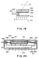
- Figure 19 is an illustration for describing a relationship between a display region of the liquid crystal panel and an effective luminescent region of the backlight unit.
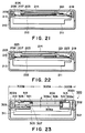
- Figure 20 is a sectional view for illustrating the state of a thermal flow from the backlight unit.
- Figures 21 - 23 are sectional views each showing a liquid crystal display apparatus according to a further embodiment of the invention.
- Figure 24 is a circuit block diagram of a display apparatus applicable to the invention.
- Figure 25A is a sectional view of a liquid crystal display apparatus according to still another embodiment of the invention, and Figure 25B is an enlarged view of a part of the apparatus shown in Figure 25A.
- a liquid crystal display apparatus includes a liquid crystal panel unit 100P, a backlight device 100B, and housings 100C1 and 100C2 that house the liquid crystal panel unit 100P and the backlight device 100B, respectively.
- the liquid crystal panel unit 100P comprises a fixing plate 150, a diffusion plate (light-transmissive plate) 159, a liquid crystal panel 101 and a peripheral circuit substrate 102.
- the fixing plate 150 is provided with an opening 150a.
- the whole peripheral part surrounding the opening 150a on the lower side of the fixing plate 150 is provided with a rib 150b, to which a diffusion plate 159 is applied to stop the opening 150a.
- the liquid crystal panel 101 is applied with a rubber-type adhesive 151 applied to the whole periphery surrounding the opening 150a so as to stop the opening 150a.
- An almost closed space (first space) 100A2 is defined by the fixing plate 150, the diffusion plate 159, the liquid crystal panel 101, etc.
- a narrow ridge 150C (which will be described in more detail hereinafter) is formed at a part on the lower side of the fixing plate 150 spaced with a prescribed gap from the rib 150b.
- a peripheral circuit plate 102 is fixed, e.g., by screwing.
- a fixing plate-supporting member 152 is disposed so as to surround the fixing plate 150.
- the fixing plate-supporting member 152 has a shape of a frame having an opening 152a.
- the fixing plate-supporting member 152 and the fixing plate 150 are spaced from each other with a certain gap which is filled with an elastic member 154 so that the fixing plate 150 is hanged in space by the fixing plate-supporting member 152 via the elastic member 154.
- the formation of or the adhesion with the elastic member 154 may be performed by disposing the fixing plate 150 within the opening 152a of the fixing plate-supporting member 152 and filling the gap between the fixing plate 150 and the fixing plate-supporting member 152 with a rubber-type adhesive, followed by curing of the adhesive.
- the fixing plate-supporting member 152 is fixed to the upper housing 100C1 of the apparatus, and an opening provided to the upper housing 100C1 is stopped with a protective plate (housing) 111.
- the protective plate 111 is formed of a glass plate which is transparent and rich in rigidity.
- An almost closed space (second space) 100A3 is defined by the apparatus upper housing 100C1, the protective plate 111, the fixing plate-supporting member 152, the elastic member 154, and the liquid crystal panel unit 100P.
- an elastic member (sponge) 161 in the form of a frame is applied along the whole periphery surrounding the opening of the upper housing 100C1 to further partition the almost closed space 100A3, thereby preventing intrusion of dust onto the surface of the liquid crystal panel 101.
- the sponge 161 is elastomeric, so that it can absorb the vibration of the liquid crystal panel 101.
- a backlight device 100B is disposed by affixation to the upper housing 100C1 with screws 158.
- the apparatus lower housing 100C2 is detachably affixed so as to protect the backlight device 100B within the housings 100C1 and 100C2.
- the backlight device 100B can be exchanged by taking apart the lower housing 100C1 and the screws 158 ( Figure 13).
- a panel control plate (not shown) is disposed so as to transform signals from a computer (not shown) into a form suitable for driving the liquid crystal panel and controlling the liquid crystal display panel.
- a frame-shaped sponge 163 is applied to the backlight device 100B so as to abut to the ridge 150C, thereby further partitioning the almost closed space 100A2 to prevent the intrusion of dust onto the luminescent surface of the backlight device 100B and the lower surface of the diffusion plate 159.
- the sponge 163 is elastomeric and functions to absorb the vibration of the liquid crystal panel 101.
- the backlight device 100B when it becomes necessary to exchange the backlight device 100B due to shortening of the life of the lamps accompanying the use of higher luminance lamps, the backlight device 100B can be easily exchanged by removing the lower housing 100C2 and the screws 158. Even during the exchange of the backlight device, the closed state of the spaces 100A2 and 100A3 formed above and below the liquid crystal panel 101 is not impaired, so that the attachment of dust onto the surfaces of the liquid crystal panel 101 (more exactly the surfaces of the polarizers 107 and 108) is prevented to remove the occurrence of display defects. As a result, the wiping for removing the dust is unnecessitated and the exchange operation can be easily performed without using a clean room.
- the diffusion plate 159 is exposed so that dust is liable to attach to the lower surface of the diffusion plate 159.
- the diffusion plate 159 is, however, not affected by a mechanical stress so that the wiping thereof can be easily performed. Further, even if the attached dust is allowed to remain, the dust is hardly recognized due to the diffusion effect of the diffusion plate per se, so that it hardly causes display defects.
- the protective plate 111 is formed of a glass plate.
- the glass plate may have a longitudinal elasticity modulus which is as large as ca. 30 times that of a transparent resin plate (e.g., an acrylic resin plate) and therefore minimize the warping in response to an external stress, such as a static pressure.
- a transparent resin plate e.g., an acrylic resin plate
- the backlight device 100B is not used to define an almost closed space as in the prior art apparatus, it is possible to form air-communicating perforations 165 in the lower housing 100C2 as shown in Figure 14, thereby improving the ventilation around the backlight device 100B.
- a major part of the heat evolved from the backlight device can be discharged outside through the perforations 165.
- a part of the heat not discharged through the perforations 165 is interrupted by the diffusion plate between the backlight device 100B and the liquid crystal panel 101. Accordingly, the heat transmitted to the liquid crystal panel 101 due to the convection in the space 100A2 is considerably reduced, and the temperature distribution is uniformized.
- the diffusion plate 159 is applied to the fixing plate 150 and is used to define the closed space 100A2. This is not necessary, but it is possible to dispose a transparent plate (light-transmissive plate) 166 only for defining the closed space and allow the diffusion plate 159 to be fixed onto the surface of the backlight 100B as shown in Figure 15.
- the light source in the backlight device is constituted by fluorescent lamps but this is of course not necessary. Other light sources may be used, and the backlight need not be placed right below the liquid crystal panel but can be placed on a side of the liquid crystal panel.
- Figure 16 shows another embodiment of the present invention.
- a fixing plate-supporting member 152 is affixed to a frame member 168 having a sectional shape close to character "L".
- the frame member 168 has an opening 168a, that is stopped by a protective plate (housing) 111.
- the protecting plate 111, the frame member 168, the fixing plate-supporting member 152, an elastic member 154 and a liquid crystal panel unit 100P define an almost closed space (second space) 100A3.
- a sponge 161 is applied along the whole periphery of the opening 168a of the frame member 168 to further partition the almost closed space 100A3, thereby preventing the intrusion of dust onto the surface of the liquid crystal panel 101.
- the frame member 168 is affixed to an upper housing 100C2, to which a lower housing 100C4 is detachably affixed so as to house the liquid crystal panel unit 100P, etc.
- This embodiment provides advantageous effects similar to those attained by the first embodiment described above.
- the backlight can be detached while retaining the closed state of the space surrounding the liquid crystal panel.
- the wiping for removing the dust is unnecessitated and the exchange operation can be easily performed without using a clean room.
- the light-transmissive plate is exposed so that dust is liable to attach to the light-transmissive plate, but the light-transmissive plate is not affected by a mechanical stress, so that the wiping thereof can be easily performed without causing display defects.
- the vibration of the liquid crystal panel is quickly attenuated due to the air damper effect of the second space, whereby the deterioration in display quality of the liquid crystal panel is obviated.
- the housing opposing the liquid crystal panel is formed of glass, the glass portion is not readily warped, so that the air damper effect of the second space is better exhibited and the vibration of the liquid crystal panel is more effectively attenuated.
- the ventilation around the backlight can be improved, thereby discharging a major part of the heat generated from the backlight to outside.
- the light-transmissive plate functions to suppress a heat transfer from the backlight to the liquid crystal panel, so that the heat transfer to the liquid crystal panel is minimized and the temperature distribution is uniformized.
- a diffusion plate 212 is fixed onto a lower face of a panel-fixing plate (supporting member) 206 so as to define a closed space 221 in combination with a liquid crystal panel 203 and the panel fixing plate 206.
- the panel-fixing plate 206 is supported by a fixing plate-supporting member 209 via an elastic member 208, and the fixing plate-supporting member 209 is fixed to an apparatus upper housing 213.
- the upper housing is provided with an opening at a part corresponding to the liquid crystal panel 203, and the opening is stopped with a display plate 214 for protecting the liquid crystal panel 203.
- a backlight unit 211 is affixed by screws 220 so as to cover a lower part of the diffusion plate 212.
- the backlight unit 211 is composed of a backlight unit-supporting member 225, and a backlight 226 fixed to a lower part of the supporting member 225.
- the lower housing 210 is detachably affixed to the upper housing 213.
- the panel fixing plate 206 may be bonded to the fixing plate-supporting member 209 with an elastic member 208 by disposing the panel-fixing plate 206 within an opening 218 of the fixing plate-supporting member 209 and the panel-fixing plate 206 with a rubber-type adhesive, which is then cured.
- a closed space 219 above the liquid crystal panel 203 is defined by the panel-fixing plate 206, the fixing plate-supporting member 209, the upper housing 213 and the display plate 214, and a closed space 227 below the diffusion plate 212 is defined by the panel-fixing plate 206, the fixing plate-supporting member 209 and the backlight unit 211.
- the spaces 219 and 227 may have a function of attenuating the vibration of the liquid crystal panel 203, when it is caused together with the vibration of the panel-fixing plate 206, etc., due to the air damper effect.
- the backlight unit 211 can be exchanged by detaching the lower housing 210 and the screws 220 ( Figure 18).
- the closed state of the space 211 formed below the liquid crystal panel 203 is not impaired, so that the attachment of dust onto the surface of the liquid crystal panel 203 (more exactly the lower surface of the polarizing film 201) is prevented to remove the occurrence of display defects.
- the wiping for removing the dust is unnecessitated and the exchange operation can be easily performed without using a clean room.
- the diffusion plate 212 is exposed so that dust is liable to attach to the lower surface of the diffusion plate 212.
- the attached dust is hardly recognized due to the diffusion effect of the diffusion plate 212 per se, so that it hardly causes display defects.
- the diffusion plate 212 just below the liquid crystal panel 203 as described above, it is possible to obtain an effect similar to that obtained by disposing the luminescent face of the backlight unit 211 closer to the liquid crystal panel 203, and it becomes possible to narrow the effective luminescent region L0 of the backlight while retaining a prescribed distance between the liquid crystal panel 203 and the backlight unit 211 ( Figure 19).
- the backlight unit 211 can be made smaller in size, and the backlight unit 211 can be reduced in size to make smaller the entire liquid crystal display apparatus.
- the backlight unit 211 is not used to define an almost closed space as in the prior art apparatus, it is possible to form air-communicating perforations 224, thereby improving the ventilation around the backlight unit 211.
- a major part of the heat evolved from the backlight unit 211 can be discharged outside through the perforations 224.
- a part of the heat not discharged through the perforations 224 is interrupted by the diffusion plate 212 between the backlight unit 211 and the liquid crystal panel 203. Accordingly, the heat transmitted to the liquid crystal panel 203 due to the convection in the space 212 is considerably reduced, and the temperature distribution is uniformized.
- the diffusion plate 212 is applied to the lower side of the panel fixing plate 206. This is not necessary, and it is also possible to dispose the diffusion plate 212 within an opening of the panel-fixing plate 266 as shown in Figure 21.
- Figure 22 shows another embodiment of the present invention.
- a panel-fixing plate 222 is used in place of the panel-fixing plate 206 and the diffusion plate 212 in the above embodiment.
- the panel-fixing plate 222 comprises a material which is light-transmissive and has a light-diffusing effect, and the liquid crystal panel 203 is affixed thereto via an adhesive 207.
- a closed space 221 is defined between the liquid crystal panel 203 and the panel-fixing plate 222, and an end of the panel-fixing plate 222 is affixed to the fixing plate-supporting member 209.
- a light-interrupting mask 222 is affixed for demarcation.
- a diffusion plate disposed in the vicinity of a liquid crystal panel is used to define a closed space together with the liquid crystal panel, and the closed state of the space is retained even during the exchange of a backlight.
- dust attachment onto the liquid crystal panel surface can be obviated, and the wiping operation for removal of the dust is unnecessitated.
- no liability of display defects due to dust attachment is involved, and the backlight can be exchanged easily without using a clean room.
- the diffusion plate is exposed so that dust is liable to attach to the surface thereof but the dust is not readily recognizable because of light-diffusion by the diffusion plate, thus being unlikely to cause display defects.
- the disposition of a diffusion plate close to the liquid crystal panel has an effect similar to that obtained by disposing the backlight closer to the liquid crystal panel, so that it becomes possible to reduce the effective luminescent region of the backlight while retaining a prescribed spacing between the liquid crystal panel and the backlight.
- the backlight can be reduced in size, and the entire liquid crystal display apparatus can be made smaller.
- the ventilation around the backlight can be improved by forming perforations in the housing, so that a major part of the heat evolved from the backlight can be discharged outside through the perforations. Further, a part of the heat not discharged through the perforations can be interrupted by the diffusion plate disposed between the backlight and the liquid crystal panel. As a result, the heat transferred to the liquid crystal panel due to convection within the closed space can be considerably reduced, and the temperature distribution is uniformized.
- an elastic member 321 of, e.g., polyester-polyurethane foa (e.g., "MOLTOPREN" (trade name), available from INOAC corp.) is disposed at the innermost position in a non-display region 300B of a liquid crystal panel 306 between the liquid crystal panel 306 and a display plate 303 (transparent portion of a housing 302).
- the elastic member 321 is in the form of a frame surrounding a display region 300A and is composed of a light-nontransmissive material so that the interior of the liquid crystal display apparatus 320 cannot be observed.
- the elastic member 321 is held by being sandwiched between the liquid crystal panel 306 and the display plate 330, and the upper face thereof contacts a printed portion 313.
- the light-nontransmissive member 321 is disposed at a gap between the liquid crystal panel 306 and the display plate 303, the members inside the display apparatus, such as a TAB film 309, cannot be recognized from outside. Further, the deformation of the display plate 303 is suppressed by the member 321 to keep constant the gap between the liquid crystal panel 306 and the display plate 303. Further, as the member 321 is an elastic member, even if an external force is applied to the display plate, the external force 321 is attenuated by the member 321.
- the members such as the TAB film 309 are hidden by the elastic member 321 and not recognized from outside, so that the appearance of the liquid crystal display apparatus 320 can be improved. Further, even if an external force is applied to the display plate 303, the deformation of the display plate 303 is regulated by the elastic member 321, so that a possible damage of the liquid crystal panel 306 due to contact with the display plate 303 can be prevented. Accordingly, it is not required to compose the display state 303 of a material having an unnecessarily high rigidity in order to prevent the deformation of the display plate 303 and it is possible to obviate the increase in cost or weight.
- the light-interrupting member is composed of not a rigid material but an elastic material, a vibration or impact applied to the display plate can be attenuated. Further, even if a vibration or impact is transmitted to the liquid crystal panel 306 via a fixing member 305, the vibration etc. can be quickly attenuated by the elastic member 321 so as to minimize the display quality deterioration of the liquid crystal panel.
- the elastic member 321 is sandwiched between the liquid crystal panel 306 and the display plate 303.
- the elastic member 321 can be, however, bonded to the liquid crystal panel 306 or to the display plate 303.
- the upper face of the elastic member 321 is caused to contact the display plate 303 for the purpose of, e.g., suppressing the deformation of the display plate 303.
- the housing 302 has an opening 302a having an area substantially equal to that of the display region 300A, the upper face of the elastic member 321 can directly contact the housing 302 instead of the display plate 303.
- the liquid crystal display apparatus 320 may be connected to a scan signal application circuit 3402 and a data signal application circuit 3403, which are further sequentially connected to a scan signal control circuit 3404 and a data signal control circuit 3406, respectively, then to a drive control circuit 3405 and a graphic controller 3407, so that data and a scan scheme signal are respectively supplied from the graphic controller 3407 to the scan signal control circuit 3402 and the data signal control circuit 3403 via the drive control circuit 3405.
- the data is converted into address data and display data by the circuits 3403 and 3406, respectively.
- the scanning scheme signal is supplied, as it is, to the scan signal application circuit 3402 and the data signal application circuit 3403.
- the scan signal application circuit 3402 supplies a scan signal having a waveform determined by the scan scheme signal to a scan electrode determined by the address data.
- the data signal application circuit 3403 supplies data signals determined by both of the display data determining a white or dark display state and the scan scheme signal.
- the interior (non-display region) of the liquid crystal display apparatus is prevented from observation so that the appearance of the liquid crystal display apparatus can be improved. Further, even if an external force is applied to the housing, particularly a transparent portion thereof, the deformation thereof is suppressed by the elastic member so that the liquid crystal panel is prevented from being damaged by contact. Accordingly, it is not required to use a material having an unnecessarily rigid material for preventing the deformation thereof so that it is possible to obviate the increase in cost and weight of the liquid crystal display apparatus. Further, the light-interrupting member is an elastic member and not a rigid member, a vibration or impact applied to the housing can be attenuated thereby. Further, even if the liquid crystal panel is vibrated for some reason, the vibration can be quickly attenuated by the elastic member, so that the deterioration in display image quality of the liquid crystal panel is minimized.
- a plurality of coil-shaped springs 423 are disposed between a fixing frame 406 and a fixing plate (cell-supporting member) 403, and a display unit 400U is supported by the coil springs 423 in the form of being hanged in space.
- the coil springs 423 do not stop the gap between the fixing frame 406 and the fixing plate 403, so that a space 425 defined by a panel or cell 402, a backlight 405, etc., is not a closed one.
- Each coil spring 423 may comprise a material selected from metals, resins and composite materials of a metal and a resin.
- the springs 423 may preferably be disposed in a plurality for each of the four sides of the fixing plate 403, i.e., the four sides of the display panel 402.
- the coil springs showing an elasticity are disposed between the fixing frame 406 and the fixing plate 403, and a rubber-type adhesive also showing an elasticity is also disposed between the fixing plate 403 and the panel 402, so that an external impact or vibration is attenuated by the coil springs 423 and the adhesive 402 and is not readily transmitted to the panel 402.
- the display unit 400U is supported by the coil springs 423, which do not cause a substantial decrease in elasticity even in a long term of use and can thus retain the vibration attenuation effect to suppress the occurrence of alignment defects in the panel 402.
- This effect is particularly advantageous if the panel is as large as having a diagonal size in excess of 20 inches.
- similar effects can be attained even in case where the panel 402 is used in an upright position as shown in Figure 25A and 25B and the whole weight of the display unit 400U is not distributed to all the coil springs 423 but a specific part thereof (i.e., those springs disposed below the panel 402 and the fixing plate 403).
- the coil springs can be disposed only on the upper and lower sides, so that the number thereof can be reduced and the production can be simplified.
- the backlight 405, etc. is not a closed one. Accordingly, the convection of air surrounding the panel 402 is not hindered and the temperature increase of the panel 402, etc., can be suppressed in spite of heat evolution from the panel 402 and the backlight 405, so that the deterioration in display quality can be suppressed. Further, as the air in the vicinity of the panel need not be packed or closed, the liquid crystal display apparatus can be simplified in structure and produced at a lower cost.
- Vop ⁇ 25 volts and a pulse width of 51.2 dsec
- Table 1 Increased temp. at the top part Minimum gravitational acceleration causing alignment failure
- Example 1 19.5 o C 80 G
- Example 1 25.5 o C 60 G
- Example apparatus showed a suppressed temperature increase of 19.5 o C (smaller by 6 o C compared with a conventional apparatus) and an increased impact resistance of 80 G (increased by 20 G compared with the conventional apparatus).
- the display unit is supported by coil springs 423 in the above embodiment but can be supported by other shapes of springs which may for example comprise metallic or plastic bars shaped into hairpins, or metallic or plastic plates shaped into the shape of character of "U" or hairpin.
- the rubber-type adhesive 407 is used to attenuate the vibration and also to bond the panel 402 to the fixing plate 403 in the above embodiment, but other elastic members, like springs, can also be disposed between the panel 402 and the fixing plate 403 so as to attenuate the vibration.
- the elastic members may be bonded to the panel 402 and to the fixing plate 403 by using, e.g., a non-elastic adhesive.
- the panel and the panel-supporting member are supported in the form of being hanged by spring members disposed between a fixing frame and the panel-supporting member, so that an external impact or vibration is attenuated by the spring members and the transmission thereof to the panel is suppressed.
- a display apparatus having a larger cushioning effect in response to a mechanical stress such as vibration or impact, thereby suppressing the occurrence of alignment defects.
- the spring members do not cause a substantial decrease in elasticity even in a long term of use but retain a lasting effect of attenuating the vibration, so that the occurrence of alignment defects in the liquid crystal panel can be suppressed.
- This effect is particularly pronounced in a large-sized panel having a diagonal size exceeding 20 inches and for a panel used in an upright position wherein the entire weight of the panel, etc., is not uniformly dispersed but is concentrated at a specific part (i.e., the part below the panel etc.).
- the liquid crystal display apparatus can be made simpler in structure and produced at a lower cost.
- a liquid crystal display apparatus is constituted by: a housing; a liquid crystal panel comprising a liquid crystal disposed between a pair of substrates each provided with electrodes, the liquid crystal panel being affixed to the housing; and a backlight for illuminating the liquid crystal panel, detachably affixed to the housing.
- a light-transmissive plate such as a diffusion plate, allowing transmission of light from the backlight is further disposed between the liquid crystal panel and the backlight so as to define an almost closed first space in cooperation with the liquid crystal panel, whereby the first space retaina its almost closed state even when the backlight is detached from the housing.
Abstract
Description
- The present invention relates to a liquid crystal display apparatus.
- Hitherto, various forms of liquid crystal display apparatus have been proposed as disclosed in Japanese Laid-Open Patent Application (JP-A) 2-93425, JP-A 3-203773 and JP-A 4-106529. Figure 1 shows an example of such apparatus.
- Referring to Figure 1, the liquid crystal display apparatus includes a
liquid crystal panel 101 and abacklight device 100B, respectively housed in acover 110. Theliquid crystal panel 101 comprises a pair of glass substrates 101a and 101b sandwiching a liquid crystal. The two glass substrates 101a and 101b are respectively provided with transparent electrodes at their inner surfaces. Polarizers 107 and 108 are applied onto both sides of theliquid crystal panel 101. To a side of theliquid crystal panel 101, a flexible printed wire film ("TAB film") 103 loaded with a drive IC is connected, and aperipheral circuit plate 102 of a drive IC for driving theliquid crystal panel 101 is connected to theTAB film 103. On the other hand, thebacklight device 100B includesfluorescent lamps 104, areflection plate 105 and adiffusion plate 106 so that a light flux from afluorescent lamps 104 is reflected by thereflection plate 105, diffused by thediffusion plate 106 and then cast at a uniform luminance onto theliquid crystal panel 101. Theliquid crystal panel 101 is fixed onto the cover 10 composed of a plate metal or a resin via acushioning member 109 comprising, e.g., rubber. - In the above-described type of liquid crystal display apparatus, only the
cushioning member 109 is disposed between theliquid crystal panel 101 and thecover 110, and a vibration or impact applied to thecover 110 is transmitted to theliquid crystal panel 101 without substantial attenuation, so that theliquid crystal panel 101 receiving a mechanical stress is liable to cause a degradation in display quality. The liquid crystal injected into theliquid crystal panel 101 may be a nematic liquid crystal or a ferroelectric liquid crystal, of which the ferroelectric liquid crystal is weaker against a mechanical stress compared with the nematic liquid crystal. Accordingly, the above difficulty is particularly pronounced in the liquid crystal display apparatus using a ferroelectric liquid crystal. - In order to solve the above problem, a liquid crystal display apparatus as shown in Figure 2 has been proposed.
- In the liquid crystal display apparatus shown in Figure 2, cushioning members (an adhesive 113 and a
resin 115 described hereinafter) for supporting aliquid crystal panel 101 are disposed in two layers, and an almost closed space 100A1 is formed below theliquid crystal panel 101 so as to cause an air damper effect (details of which will be described later), thereby increasing the performances of attenuating the vibration and/or impact. - More specifically, the liquid crystal display apparatus shown in Figure 2 is equipped with a
fixing plate 112 which is provided with an opening 112a and remains like a picture frame. Theliquid crystal panel 101 having a structure described above is applied onto thefixing plate 112 with an elastic adhesive applied at all the peripheral part surrounding the opening 112a, whereby the opening 112a is stopped by theliquid crystal panel 101. The above-mentionedperipheral circuit plate 102 is fixed onto thefixing plate 112. Surrounding thefixing plate 112, aframe member 114 is disposed with a prescribed spacing, and thefixing plate 112 is supported in the form of being hanged in space with theframe member 114 via anelastic resin 115. Further, above theframe member 114, a frame-shaped fixing plate 115 provided with a central opening is fixed, and the opening of thefixing plate 115 is stopped with a protective plate comprising a transparent sheet like that of glass. On the lower side of the protective plate 111, apolarizer 118 is applied. On the other hand, on the lower part of theframe member 114, abacklight device 100B is affixed, and an almost closed space 100A1 is defined by thebacklight device 100B, theliquid crystal panel 101, thefixing plate 112, etc. On the upper surface of thediffusion plate 106, a polarizer applied onto a transparent sheet of glass, etc., is disposed. - When a vibration or impact is applied to the
frame member 114 in the above-described liquid crystal display apparatus, the vibration, etc., is attenuated by theresin 115 and adhesive 113 and not substantially transmitted to theliquid crystal panel 101. Further, even if theliquid crystal panel 101 is vibrated to some extent, the vibration is quickly attenuated by the air damper effect due to air within the almost closed space 100A1. More specifically, when theliquid crystal panel 101 is vibrated, the space 100A1 causes repetitive contraction and expansion, the contraction and expansion function as a resistance to the vibration of theliquid crystal panel 101 due to the almost closed state of the space 100A1, so that the vibration is quickly attenuated while receiving a cushioning effect of the space 100A1. In this way, theliquid crystal panel 101 is protected from a mechanical stress and is thus free from a deterioration in display quality due to such a mechanical stress. - Incidentally, in case of a liquid crystal panel having a low transmittance, such as a color liquid crystal panel, it is necessary to use a
backlight device 100B equipped with high-luminancefluorescent lamps 104 in order obtain a desired level of luminance. In case of using intensified luminancefluorescent lamps 104, thelamps 104 are supplied with an increased load, and thus the life of thefluorescent lamps 104 is shortened, so that it becomes necessary to frequently exchange thewhole backlight device 100B and thefluorescent lamps 104. - At the time of exchanging the
backlight device 100B, however, it is necessary to detach thebacklight device 100B from the upper (or remaining) part (inclusive of theliquid crystal panel 101,frame member 114, etc.) as shown in Figure 3. As a result, the closed state of the almost closed space 100A1 formed below theliquid crystal panel 101 is temporarily broken and the lower surface of theliquid crystal panel 101 is exposed, whereby dust or dirt is liable to attach to the lower surface. The attached dust, etc., even if it is sufficiently small as not recognized by human eyes, can cause display defects, and a wiping operation as required for removing the attached dust is not desirable as it applies an external force to thepanel 103. Particularly, in case of a liquid crystal display apparatus using a ferroelectric liquid crystal, the alignment of the liquid crystal is liable to be disordered, thus failing to provide a display. On the other hand, if the exchange of abacklight device 100B is performed in a clean room so as to obviate the dust attachment, the operation becomes troublesome and not practical. - Figure 4 shows another example of known liquid crystal display apparatus. Referring to Figure 4, the liquid crystal display apparatus includes a
liquid crystal panel 203 comprising a liquid crystal disposed between a pair ofsubstrates liquid crystal panel 203 is provided with polarizingfilms liquid crystal panel 101, a flexible printed wire film ("TAB film") 204 loaded with a drive IC is connected, and aperipheral circuit plate 102 for a drive IC for driving theliquid crystal panel 203 is connected to theTAB film 204. On the other hand, the liquid crystal display apparatus is equipped with a panel-fixing plate 206, and the panel-fixing plate 206 is provided with anopening 217. At the entire periphery of the panel-fixing plate 206 surrounding the opening, anelastomeric adhesive 207 is applied so as to fix theliquid crystal panel 203 onto the panel-fixing plate, so that theliquid crystal panel 203 stops theopening 217. Further, the panel-fixing plate 206 is supported in the form of being hanged in space by a fixing plate-supportingmember 209 via anelastic member 208 and, to the lower part of the fixing plate-supportingmember 209, abacklight unit 211 is affixed and, below theliquid crystal panel 203, an almost closedspace 200A is defined by the panel-fixing plate 206, the fixing plate-supportingmember 209, thebacklight unit 211, the adhesive 207 and theelastic member 208. - The
backlight unit 211 includes tubular lamps such as thermal cathode tubes (not shown) and adiffusion plate 212 above the lamps. Thediffusion plate 212 is used to scatter and diffuse light from the lamps so that the scattered and diffused light is caused to illuminate theliquid crystal panel 203. The above-describedbacklight unit 211,liquid crystal panel 203, etc., are fixed to ahousing 210 of the apparatus. - The above-described liquid crystal apparatus shown in Figure 4 has the following advantageous features.
- (1) The
liquid crystal panel 203 is supported by theelastic member 208 so that, even if thehousing 210 is supplied with an impact, the vibration is not readily transmitted to theliquid crystal panel 203. - (2) Even when the
liquid crystal panel 203 is directly supplied with an external force, theliquid crystal panel 203 supported in hanging with theelastic member 208 is allowed to move to some extent, so that the ill effects given by the external force, such as a deterioration in alignment of liquid crystal due to warping of theliquid crystal panel 203, can be minimized. - (3) Further, because of the almost closed
space 200A formed below theliquid crystal panel 203, the vibration of theliquid crystal panel 203 can be quickly attenuated due to the air damper effect of thespace 200A. More specifically, in case where theliquid crystal panel 203 is vibrated to move in a direction of an arrow "-Z" shown in Figure 5, theliquid crystal panel 203 receives a resisting force from the closedspace 200A to be compressed. Also, in case where theliquid crystal panel 203 is caused to move in a direction of an arrow "+Z", the panel also receives a similar resisting force so that the vibration of theliquid crystal panel 203 is quickly attenuated. As a result, the deformation of theliquid crystal panel 203 is reduced to suppress the deterioration of alignment and image quality. - (4) Further, as the closed space is formed, the attachment of dust or dirt onto the lower surface of the liquid crystal panel 203 (more exactly, the lower surface of the polarizer film thereof) can be prevented, thereby preventing the deterioration in display quality.
- Incidentally, increases in contrast and brightness of a
liquid crystal panel 203 have been desired in these years and accordingly thebacklight unit 211 is desired to use a lamp of a higher luminance. On the other hand, it is also known that a lamp of a higher luminance is caused to have a shorter life because of an increased load (e.g., ca. 10000 hours in case of a thermal cathode tube). Accordingly, in such a case, frequent exchange of lamps is required. More specifically, it is necessary to exchange thebacklight unit 211 in a state where an upper part (including theliquid crystal panel 203, the fixing plate-supportingmember 209, etc.) of the liquid crystal display apparatus is taken apart from thehousing 210, as shown in Figure 6. - However, at the time of the exchange of the backlight unit, the surface of the liquid crystal panel 203 (the lower surface of the polarizer film) is exposed, so that dust or dirt is liable to attach thereto. The attached dust etc., even if it is small enough to be not recognized by human eyes, can cause display defects, and a wiping operation required for removing the attached dust is not desirable as it applied an external force to the panel. Further, if the backlight unit is exchanged in a clean room so as to obviate the dust attachment, the operation becomes troublesome and impractical.
- Incidentally, there is a relationship as represented by the following equation (with reference to Figure 7) between an effective luminescent region L of a backlight and a distance d between the back surface of the
liquid crystal panel 203 and the luminescent surface of the backlight unit 211:

wherein
- d
- >> t,
- L0:
- display region of the liquid crystal panel
- t:
- the liquid crystal panel thickness
- ϑ:
- viewing angle of the liquid crystal panel
- φ:
- refraction angle.
- In the case where the
liquid crystal panel 203 is supported in a hanged state together with the panel-fixingplate 206 as in the above-described example, the spacing d changes along with the vibration of theliquid crystal panel 203, so that it is necessary to increase the effective luminescent region L while taking the maximum value of the spacing d into consideration. As a result, there arises a difficulty that the backlight unit is enlarged in capacity. - Figure 8 shows another example of known liquid crystal display apparatus including a liquid crystal panel and a backlight device supported integrally. Referring to Figure 8, the liquid
crystal display apparatus 301 includes anupper housing 302 including anopening 302a and a transparent display plate (transparent part) 303 stopping theopening 302a. The inner side of theupper housing 302 is provided withbosses 302b, to the lower ends of which a panel-fixingmember 305 is horizontally supported. The fixingmember 305 is in the form of a picture frame surrounding a central opening. On the lower surface of the fixingmember 305, aliquid crystal panel 306 is applied with an adhesive 307 so as to stop theopening 305a. Theliquid crystal panel 306 comprises twoglass substrates substrates liquid crystal panel 306 has polarizing films (not shown) attached thereto on both sides. Further, to a side of theliquid crystal panel 306, aTAB film 309 loaded with a drive IC is connected, and aperipheral circuit substrate 310 for the driver IC for driving the liquid crystal panel 306 (hereinafter called "driver board 310") is connected to theTAB film 309. Thedriver board 310 is screwed to the fixingmember 305. On the other hand, to the lower surface of the fixingmember 305, abacklight device 311 is affixed. As is known, thebacklight device 311 includes fluorescent lamps, a reflection plate and a diffusion plate so as to illuminate theliquid crystal panel 306 at a uniform luminance. To theupper housing 302, alower housing 312 is detachably supported, and theliquid crystal panel 306, etc., are housed within thehousing - In the above-described liquid crystal display apparatus, a prescribed spacing d is provided between the display plate 303 (the lower surface of the upper housing 302) and the
liquid crystal panel 306 so that thedisplay plate 303 will not touch theliquid crystal panel 306 even when the display plate is deformed by receiving an external force. A region outside thedisplay region 300A of theliquid crystal panel 306 should desirably be not seen from the outside because of an improved appearance and, for this purpose, a portion in the non-display region 303C of the lower surface of the display plate is provided with a printedframe 313 for light interception. - A large spacing d between the display plate 303 (upper surface of the housing 302) and the
liquid crystal panel 306 is not desirable because it gives an impression that the panel face is depressed inside. For this reason, it is a current practice to adopt a structure wherein theliquid crystal panel 306 is fixed on the upper surface of the fixingmember 305 to provide a small spacing d as shown in Figure 9. - However, in a liquid crystal display apparatus adopting the structure, there arises a difficulty that the inner materials inclusive of the
TAB film 309 anddriver board 310 can be easily recognized through the spacing as shown in Figure 10, thus providing an awkward appearance. - Further, because of a decreased spacing d, it has been required to provide a rigid material for the
display plate 303 in order to prevent the damage of the liquid crystal panel. - Figure 11 shows another example of known liquid crystal display apparatus using a ferroelectric liquid crystal.
- Referring to Figure 11, the liquid
crystal display apparatus 401 principally includes aliquid crystal cell 402, a fixing member (cell-supporting member) 403 for supporting thecell 402, and abacklight 405, which are supported by a fixingframe 406. - The
cell 402 comprises a ferroelectric liquid crystal sandwiched between a pair of glass substrates each having thereon transparent electrodes and supplied with an aligning treatment. The fixingplate 403 is composed of, e.g., a plastic or metal plate, and is provided with an opening which is a little smaller than thecell 402. At a peripheral part surrounding the opening of the fixingplate 403, a rubber-type adhesive 407 is applied, and thecell 402 is applied therewith so as to stop the opening. Thecell 402 is provided with anupper polarizer 409 and alower polarizer 410 applied onto both sides. To the takeout electrodes of thecell 402, a flexible printedwire film 411 is connected, and acircuit substrate 412 for driving thecell 402 is electrically connected to the printedwire film 411. Thecircuit substrate 412 is fixed to the fixingplate 402 with screws, etc. Hereinafter, a unit including the fixingplate 403, thecell 402, the upper andlower polarizers wire film 411 and the circuit substrate, is called a "display unit U". - The display unit U is supported in the form of being hanged in space by the fixing
frame 406 as the whole periphery of the fixingplate 403 is applied with the rubber-type adhesive 413. To the lower side of the fixingframe 406, thebacklight 405 is affixed. Adiffusion plate 408 is applied onto the surface of thebacklight 405. An almost closedspace 415 is defined by thebacklight 405, the fixingframe 406, the fixingplate 403 and thecell 402, so that the vibration, if any, of thecell 403 is quickly attenuated due to the air damper effect of the almost closedspace 415. To the upper part of the fixingframe 406, adisplay plate 417 is affixed via acover 416, so as to protect thecell 402, etc., thereby. - In the liquid
crystal display apparatus 401 constituted in the above-described manner, a rubber-type adhesive 413 is disposed between the fixingframe 406 and the fixingplate 403, and a similar elastic rubber-type adhesive 407 is disposed between the fixingplate 403 and thecell 402, so that an external impact or vibration can be attenuated by theadhesives cell 402. Further, as the almost closedspace 415 is formed by thebacklight 405, the fixingframe 406, the fixingplate 403 and thecell 402, a slight degree of vibration, if any, of thecell 402 can be quickly attenuated by the air damper effect of the almost closedspace 415. As a result, the warping of thecell 402 is suppressed to the minimum, whereby the occurrence of alignment defects and lowering in display quality peculiarly encountered with a ferroelectric liquid crystal cell can be suppressed. - In the above-described liquid
crystal display apparatus 401, the display unit U is supported by a rubber-type adhesive disposed on the four sides of the display unit U. Accordingly, there can arise a problem that therubber adhesive 413 can cause a lowering in elasticity due to deterioration in long term use, thus failing to provide a complete attenuation of vibration and resulting in alignment defects in thecell 402. This problem is not so conspicuous if thecell 402 is as small as at most 15 inches but is conspicuous if the cell is as large as 20 inches or larger. Particularly, such a large size panel is generally used in an upright position as in a desktop word processor and, in such a case, the total weight of the display unit U is not dispersed to the entirety of the rubber-type adhesive but is concentrated at particular parts, at which the adhesive 413 is liable to cause an accelerated deterioration. - On the other hand, during the drive of a liquid crystal display apparatus, heat is generated from the
cell 402,backlight 405 andcircuit substrate 412. In case where an almostclosed space 415 is formed surrounding thecell 402 as in the above example, the air surrounding the cell is prevented from convection, so that the temperature of thecell 402 is increased, thereby causing a deterioration of display quality. - As described above, the conventional liquid crystal display apparatus has been found to involve several technical problems, the solution of which given by the present invention will become apparent in view of the following description.
- A first object of the present invention is to provide a liquid crystal display apparatus capable of preventing dust attachment onto a liquid crystal panel and facilitating the exchange of a backlight by disposing a light-transmissive plate in the vicinity of the liquid crystal panel so as to form a first almost closed space capable of retaining the closed state thereof even during the exchange of the backlight.
- A second object of the present invention is to provide a liquid crystal display apparatus capable of preventing dust attachment onto a liquid crystal panel and reducing the size of a backlight by disposing a diffusion plate in the vicinity of a liquid crystal panel so as to define a closed space and retain the closed state of the space even during the exchange of the backlight.
- A third object of the present invention is to provide a liquid crystal display apparatus having an elastic member disposed at a gap between the periphery of a liquid crystal panel and an upper housing so as to provide an improved appearance, and also an information transmission apparatus including such a liquid crystal display apparatus.
- A fourth object of the present invention is to provide a ferroelectric liquid crystal display apparatus including a cell and a cell-supporting member supported in the form of being hanged in space with a spring so as to retain a vibration attenuation effect and allow air convection around the cell to suppress the temperature raise of the cell.
- According to a first aspect of the present invention, there is provided a liquid crystal display apparatus, comprising:
a housing,
a liquid crystal panel comprising a liquid crystal disposed between a pair of substrates each provided with electrodes, the liquid crystal panel being affixed to the housing,
a backlight for illuminating the liquid crystal panel, detachably affixed to the housing, and
a light-transmissive plate allowing transmission of light from the backlight, disposed between the liquid crystal panel and the backlight so as to define an almost closed first space in cooperation with the liquid crystal panel, the first space retaining its almost closed state even when the backlight is detached from the housing. - In this instance, it is preferred that the liquid crystal panel and the housing in combination define an almost closed second space, and the first space and the second space are disposed to sandwich the liquid crystal panel.
- It is also preferred that a part of the housing opposing the liquid crystal panel is formed of glass.
- It is possible to dispose an elastic member between the liquid crystal panel and the housing within the second space. The liquid crystal can be a ferroelectric liquid crystal.
- In the liquid crystal display apparatus constituted in the above-described manner, the light-transmissive plate disposed in the vicinity of the liquid crystal panel defines an almost closed first space, of which the closed state is retained even when the backlight is exchanged, whereby dust, etc., are prevented from being attached onto the liquid crystal panel on its side confronting the backlight.
- According to a second aspect of the present invention, there is provided a liquid crystal display apparatus, comprising:
a liquid crystal panel comprising a liquid crystal disposed between a pair of substrates each provided with electrodes,
a backlight for illuminating the liquid crystal panel,
a diffusion plate disposed between the backlight and the liquid crystal panel for diffusing light from the backlight, and
a housing supporting the liquid crystal panel, the backlight and the diffusion plate,
wherein the diffusion plate is disposed in the vicinity of the liquid crystal panel so as to define an almost closed space in combination with the liquid crystal panel. - In this instance, it is preferred that a supporting member having an opening is supported via an elastic member by the housing in the form of being hanged in space, the liquid crystal panel is affixed to the supporting member so as to cover one side of the opening, and the diffusion plate is affixed to the supporting member so as to cover another side of the opening, so that the liquid crystal panel, the supporting member and the diffusion plate in combination define the above-mentioned almost closed space.
- In the liquid crystal display apparatus constituted in the above-described manner, even when the backlight is detached to be exchanged, dust, etc., are prevented from being attached to the liquid crystal panel on its side confronting the backlight because the diffusion plate disposed in the vicinity of the liquid crystal panel defines a closed space in cooperation with the liquid crystal panel. The disposition of the diffusion plate close to the liquid crystal panel has a similar effect as the disposition of the backlight closer to the liquid crystal panel.
- According to a third aspect of the present invention, there is provided a liquid crystal display apparatus, comprising:
a liquid crystal panel comprising a liquid crystal disposed between a pair of substrates each provided with electrodes,
a housing disposed to house the liquid crystal panel and equipped with a transparent portion so as to allow observation of the liquid crystal panel therethrough, the transparent portion and the liquid crystal panel confronting each other with a prescribed distance therebetween,
wherein a nontransparent elastic member is disposed between the housing and the liquid crystal panel so as to surround a display region of the liquid crystal panel. - According to the present invention, there is also provided an information transmission apparatus, comprising: a graphic controller for outputting a data signal and a scanning scheme signal, a scanning signal control circuit for outputting scanning line address data and a scanning scheme signal, and the above-mentioned liquid crystal display apparatus.
- In the above-described liquid crystal display apparatus, a nontransparent elastic member is disposed between the housing and the liquid crystal panel so as to surround a display region of the liquid crystal panel, so that the interior (non-display region) of the liquid crystal display apparatus is made non-observable regardless of a gap formed between the transparent portion of the housing and the liquid crystal panel.
- According to a fourth aspect of the present invention, there is provided a ferroelectric liquid crystal display apparatus, comprising:
a liquid crystal cell comprising a ferroelectric liquid crystal disposed between a pair of substrates each provided with electrodes,
a cell-supporting member for supporting the cell,
a fixing frame for supporting the cell-supporting member, and
a spring member disposed between the fixing frame and the cell-supporting member for hanging the cell-supporting member and the cell in space. - In this instance, it is preferred that the spring member comprises a metallic bar formed in a coil or a hairpin. It is also possible that the spring member comprises a so-called plate spring or a metallic plate formed in a U-shaped or a hairpin. It is further possible that the spring member comprises a resin or a composite material of a resin and a metal.
- In the liquid crystal display apparatus constituted in the above-described manner, an external vibration or impact applied to the fixing frame is attenuated by the spring member and is not readily transmitted to the cell-supporting member or the cell. Further, the spring member does not readily lower its elasticity even in a long term of use so that its function of attenuating the vibration can be retained. Further, the spring member can be disposed between the fixing frame and the cell-supporting member without showing a space-sealing effect so that air convection is not hindered thereby.
- These and other objects, features and advantages of the present invention will become more apparent upon a consideration of the following description of the preferred embodiments of the present invention taken in conjunction with the accompanying drawings, wherein like reference numerals are used to denote like parts.
- Figures 1, 2, 4 and 8 are sectional views each showing a structure of a known liquid crystal display apparatus.
- Figures 3 and 6 are sectional views illustrating the states of exchanging backlight devices in the apparatus of Figures 2 and 4, respectively.
- Figure 5 is a sectional view illustrating the state of a liquid crystal panel having received an external force in the liquid crystal display apparatus shown in Figure 4.
- Figure 7 is an illustration for describing a relationship between a display region of the liquid crystal panel and an effective luminescent region of the backlight unit in the liquid crystal display apparatus shown in Figure 6.
- Figure 9 is a sectional view of another known liquid crystal display apparatus.
- Figure 10 is a partial enlarged view for illustrating a problem of the apparatus shown in Figure 9.
- Figure 11 is a sectional view of another known liquid crystal display apparatus.
- Figure 12 is a sectional view of a liquid crystal display apparatus according to a first embodiment of the invention.
- Figure 13 is a sectional view for illustrating the state of exchanging a backlight device in the liquid crystal display apparatus shown in Figure 2.
- Figure 14 is a sectional illustration of air flow in case where air-communicating perforations are provided to the apparatus shown in Figure 12.
- Figure 15 is a sectional view of another application of liquid crystal display apparatus according to the first embodiment.
- Figure 16 is a sectional view of a liquid crystal display apparatus according to a second embodiment of the invention.
- Figure 17 is a sectional view of a liquid crystal display apparatus according to a third embodiment of the invention.
- Figure 18 is a sectional view for illustrating the state of exchanging the backlight in the apparatus according to the third embodiment.
- Figure 19 is an illustration for describing a relationship between a display region of the liquid crystal panel and an effective luminescent region of the backlight unit.
- Figure 20 is a sectional view for illustrating the state of a thermal flow from the backlight unit.
- Figures 21 - 23 are sectional views each showing a liquid crystal display apparatus according to a further embodiment of the invention.
- Figure 24 is a circuit block diagram of a display apparatus applicable to the invention.
- Figure 25A is a sectional view of a liquid crystal display apparatus according to still another embodiment of the invention, and Figure 25B is an enlarged view of a part of the apparatus shown in Figure 25A.
- A first embodiment of the present invention will now be described with reference to Figures 12 to 14 wherein like parts are denoted by like reference numerals as in Figures 1 and 2 and the explanation thereof may be omitted.
- As shown in Figure 12, a liquid crystal display apparatus according to this embodiment includes a liquid
crystal panel unit 100P, abacklight device 100B, and housings 100C1 and 100C2 that house the liquidcrystal panel unit 100P and thebacklight device 100B, respectively. - Among these, the liquid
crystal panel unit 100P comprises a fixingplate 150, a diffusion plate (light-transmissive plate) 159, aliquid crystal panel 101 and aperipheral circuit substrate 102. The fixingplate 150 is provided with an opening 150a. The whole peripheral part surrounding the opening 150a on the lower side of the fixingplate 150 is provided with arib 150b, to which adiffusion plate 159 is applied to stop the opening 150a. Theliquid crystal panel 101 is applied with a rubber-type adhesive 151 applied to the whole periphery surrounding the opening 150a so as to stop the opening 150a. An almost closed space (first space) 100A2 is defined by the fixingplate 150, thediffusion plate 159, theliquid crystal panel 101, etc. A narrow ridge 150C (which will be described in more detail hereinafter) is formed at a part on the lower side of the fixingplate 150 spaced with a prescribed gap from therib 150b. Onto the upper surface at a part close to an end of the fixingplate 150, aperipheral circuit plate 102 is fixed, e.g., by screwing. - On the other hand, a fixing plate-supporting
member 152 is disposed so as to surround the fixingplate 150. The fixing plate-supportingmember 152 has a shape of a frame having anopening 152a. The fixing plate-supportingmember 152 and the fixingplate 150 are spaced from each other with a certain gap which is filled with anelastic member 154 so that the fixingplate 150 is hanged in space by the fixing plate-supportingmember 152 via theelastic member 154. The formation of or the adhesion with theelastic member 154 may be performed by disposing the fixingplate 150 within theopening 152a of the fixing plate-supportingmember 152 and filling the gap between the fixingplate 150 and the fixing plate-supportingmember 152 with a rubber-type adhesive, followed by curing of the adhesive. - The fixing plate-supporting
member 152 is fixed to the upper housing 100C1 of the apparatus, and an opening provided to the upper housing 100C1 is stopped with a protective plate (housing) 111. The protective plate 111 is formed of a glass plate which is transparent and rich in rigidity. An almost closed space (second space) 100A3 is defined by the apparatus upper housing 100C1, the protective plate 111, the fixing plate-supportingmember 152, theelastic member 154, and the liquidcrystal panel unit 100P. As a result, when the liquidcrystal panel unit 100P supported by hanging in space is vibrated on receiving an external impact, the vibration is quickly attenuated due to the air damper effect of the space 100A3 so that the impact transmitted to theliquid crystal panel 101 is alleviated. - On the lower surface of the upper housing 100C1, an elastic member (sponge) 161 in the form of a frame is applied along the whole periphery surrounding the opening of the upper housing 100C1 to further partition the almost closed space 100A3, thereby preventing intrusion of dust onto the surface of the
liquid crystal panel 101. Thesponge 161 is elastomeric, so that it can absorb the vibration of theliquid crystal panel 101. - Below the liquid
crystal panel unit 100P, abacklight device 100B is disposed by affixation to the upper housing 100C1 withscrews 158. To the upper housing 100C1, the apparatus lower housing 100C2 is detachably affixed so as to protect thebacklight device 100B within the housings 100C1 and 100C2. In this embodiment, thebacklight device 100B can be exchanged by taking apart the lower housing 100C1 and the screws 158 (Figure 13). At a spacing between thebacklight device 100B and the lower housing 100C2, a panel control plate (not shown) is disposed so as to transform signals from a computer (not shown) into a form suitable for driving the liquid crystal panel and controlling the liquid crystal display panel. - A frame-shaped
sponge 163 is applied to thebacklight device 100B so as to abut to the ridge 150C, thereby further partitioning the almost closed space 100A2 to prevent the intrusion of dust onto the luminescent surface of thebacklight device 100B and the lower surface of thediffusion plate 159. Thesponge 163 is elastomeric and functions to absorb the vibration of theliquid crystal panel 101. - The following advantageous effects may be given by this embodiment.
- According to this embodiment, when it becomes necessary to exchange the
backlight device 100B due to shortening of the life of the lamps accompanying the use of higher luminance lamps, thebacklight device 100B can be easily exchanged by removing the lower housing 100C2 and thescrews 158. Even during the exchange of the backlight device, the closed state of the spaces 100A2 and 100A3 formed above and below theliquid crystal panel 101 is not impaired, so that the attachment of dust onto the surfaces of the liquid crystal panel 101 (more exactly the surfaces of thepolarizers 107 and 108) is prevented to remove the occurrence of display defects. As a result, the wiping for removing the dust is unnecessitated and the exchange operation can be easily performed without using a clean room. At the time of exchanging the backlight, thediffusion plate 159 is exposed so that dust is liable to attach to the lower surface of thediffusion plate 159. Thediffusion plate 159 is, however, not affected by a mechanical stress so that the wiping thereof can be easily performed. Further, even if the attached dust is allowed to remain, the dust is hardly recognized due to the diffusion effect of the diffusion plate per se, so that it hardly causes display defects. - On the other hand, as the almost closed space 100A3 is formed above the
liquid crystal panel 101, even if the liquid crystal panel is vibrated, the vibration is quickly attenuated by the air damper effect of the space 100A3, thereby preventing the deterioration in display quality. - Further, in this embodiment, the protective plate 111 is formed of a glass plate. The glass plate may have a longitudinal elasticity modulus which is as large as ca. 30 times that of a transparent resin plate (e.g., an acrylic resin plate) and therefore minimize the warping in response to an external stress, such as a static pressure. As a result, even if the
space 103 causes repetitive expansion and contraction accompanying the vibration of the liquidcrystal panel unit 100P, so that the air damper effect of the space 100A3 is better retained and thus the vibration of the liquidcrystal panel unit 100P can be attenuated in a short time. - Further, as the
backlight device 100B is not used to define an almost closed space as in the prior art apparatus, it is possible to form air-communicatingperforations 165 in the lower housing 100C2 as shown in Figure 14, thereby improving the ventilation around thebacklight device 100B. As a result, a major part of the heat evolved from the backlight device can be discharged outside through theperforations 165. Further, a part of the heat not discharged through theperforations 165 is interrupted by the diffusion plate between thebacklight device 100B and theliquid crystal panel 101. Accordingly, the heat transmitted to theliquid crystal panel 101 due to the convection in the space 100A2 is considerably reduced, and the temperature distribution is uniformized. - In the above embodiment, the
diffusion plate 159 is applied to the fixingplate 150 and is used to define the closed space 100A2. This is not necessary, but it is possible to dispose a transparent plate (light-transmissive plate) 166 only for defining the closed space and allow thediffusion plate 159 to be fixed onto the surface of thebacklight 100B as shown in Figure 15. In the above embodiment, the light source in the backlight device is constituted by fluorescent lamps but this is of course not necessary. Other light sources may be used, and the backlight need not be placed right below the liquid crystal panel but can be placed on a side of the liquid crystal panel. - Figure 16 shows another embodiment of the present invention.
- In this embodiment, a fixing plate-supporting
member 152 is affixed to aframe member 168 having a sectional shape close to character "L". Theframe member 168 has anopening 168a, that is stopped by a protective plate (housing) 111. The protecting plate 111, theframe member 168, the fixing plate-supportingmember 152, anelastic member 154 and a liquidcrystal panel unit 100P define an almost closed space (second space) 100A3. On the lower face of the frame member, asponge 161 is applied along the whole periphery of theopening 168a of theframe member 168 to further partition the almost closed space 100A3, thereby preventing the intrusion of dust onto the surface of theliquid crystal panel 101. Theframe member 168 is affixed to an upper housing 100C2, to which a lower housing 100C4 is detachably affixed so as to house the liquidcrystal panel unit 100P, etc. - This embodiment provides advantageous effects similar to those attained by the first embodiment described above.
- As described above, according to this aspect of the invention, even when it becomes necessary to exchange a backlight due to shortening of the life of lamps accompanying the higher luminance of the lamps, the backlight can be detached while retaining the closed state of the space surrounding the liquid crystal panel. As a result, the wiping for removing the dust is unnecessitated and the exchange operation can be easily performed without using a clean room. At the time of exchanging the backlight, the light-transmissive plate is exposed so that dust is liable to attach to the light-transmissive plate, but the light-transmissive plate is not affected by a mechanical stress, so that the wiping thereof can be easily performed without causing display defects.
- Further, in the case of defining an almost closed second space with the liquid crystal panel and a housing, the vibration of the liquid crystal panel is quickly attenuated due to the air damper effect of the second space, whereby the deterioration in display quality of the liquid crystal panel is obviated. In this instance, if a portion of the housing opposing the liquid crystal panel is formed of glass, the glass portion is not readily warped, so that the air damper effect of the second space is better exhibited and the vibration of the liquid crystal panel is more effectively attenuated.
- Further, as it is unnecessary to use the backlight for defining a closed space, the ventilation around the backlight can be improved, thereby discharging a major part of the heat generated from the backlight to outside. Further, the light-transmissive plate functions to suppress a heat transfer from the backlight to the liquid crystal panel, so that the heat transfer to the liquid crystal panel is minimized and the temperature distribution is uniformized.
- A third embodiment of the present invention will now be described with reference to Figures 17 to 20 wherein similar parts as in Figure 4 are denoted by identical reference numerals and repetitive description will be omitted.
- Referring to Figure 17, in this embodiment, a
diffusion plate 212 is fixed onto a lower face of a panel-fixing plate (supporting member) 206 so as to define aclosed space 221 in combination with aliquid crystal panel 203 and thepanel fixing plate 206. The panel-fixingplate 206 is supported by a fixing plate-supportingmember 209 via anelastic member 208, and the fixing plate-supportingmember 209 is fixed to an apparatusupper housing 213. The upper housing is provided with an opening at a part corresponding to theliquid crystal panel 203, and the opening is stopped with adisplay plate 214 for protecting theliquid crystal panel 203. Below theupper housing 213, abacklight unit 211 is affixed byscrews 220 so as to cover a lower part of thediffusion plate 212. Thebacklight unit 211 is composed of a backlight unit-supportingmember 225, and abacklight 226 fixed to a lower part of the supportingmember 225. Thelower housing 210 is detachably affixed to theupper housing 213. Thepanel fixing plate 206 may be bonded to the fixing plate-supportingmember 209 with anelastic member 208 by disposing the panel-fixingplate 206 within anopening 218 of the fixing plate-supportingmember 209 and the panel-fixingplate 206 with a rubber-type adhesive, which is then cured. Aclosed space 219 above theliquid crystal panel 203 is defined by the panel-fixingplate 206, the fixing plate-supportingmember 209, theupper housing 213 and thedisplay plate 214, and aclosed space 227 below thediffusion plate 212 is defined by the panel-fixingplate 206, the fixing plate-supportingmember 209 and thebacklight unit 211. Thespaces liquid crystal panel 203, when it is caused together with the vibration of the panel-fixingplate 206, etc., due to the air damper effect. In this embodiment, thebacklight unit 211 can be exchanged by detaching thelower housing 210 and the screws 220 (Figure 18). - According to this embodiment, when it becomes necessary to exchange the
backlight unit 211 due to shortening of the life of the lamps accompanying the use of higher luminance lamps, the closed state of thespace 211 formed below theliquid crystal panel 203 is not impaired, so that the attachment of dust onto the surface of the liquid crystal panel 203 (more exactly the lower surface of the polarizing film 201) is prevented to remove the occurrence of display defects. As a result, the wiping for removing the dust is unnecessitated and the exchange operation can be easily performed without using a clean room. At the time of exchanging the backlight, thediffusion plate 212 is exposed so that dust is liable to attach to the lower surface of thediffusion plate 212. The attached dust is hardly recognized due to the diffusion effect of thediffusion plate 212 per se, so that it hardly causes display defects. - Further, by disposing the
diffusion plate 212 just below theliquid crystal panel 203 as described above, it is possible to obtain an effect similar to that obtained by disposing the luminescent face of thebacklight unit 211 closer to theliquid crystal panel 203, and it becomes possible to narrow the effective luminescent region L₀ of the backlight while retaining a prescribed distance between theliquid crystal panel 203 and the backlight unit 211 (Figure 19). As a result, thebacklight unit 211 can be made smaller in size, and thebacklight unit 211 can be reduced in size to make smaller the entire liquid crystal display apparatus. - Further, as the
backlight unit 211 is not used to define an almost closed space as in the prior art apparatus, it is possible to form air-communicatingperforations 224, thereby improving the ventilation around thebacklight unit 211. As a result, a major part of the heat evolved from thebacklight unit 211 can be discharged outside through theperforations 224. Further, a part of the heat not discharged through theperforations 224 is interrupted by thediffusion plate 212 between thebacklight unit 211 and theliquid crystal panel 203. Accordingly, the heat transmitted to theliquid crystal panel 203 due to the convection in thespace 212 is considerably reduced, and the temperature distribution is uniformized. - In the above embodiment, the
diffusion plate 212 is applied to the lower side of thepanel fixing plate 206. This is not necessary, and it is also possible to dispose thediffusion plate 212 within an opening of the panel-fixing plate 266 as shown in Figure 21. - Figure 22 shows another embodiment of the present invention.
- In this embodiment, a panel-fixing
plate 222 is used in place of the panel-fixingplate 206 and thediffusion plate 212 in the above embodiment. The panel-fixingplate 222 comprises a material which is light-transmissive and has a light-diffusing effect, and theliquid crystal panel 203 is affixed thereto via an adhesive 207. Aclosed space 221 is defined between theliquid crystal panel 203 and the panel-fixingplate 222, and an end of the panel-fixingplate 222 is affixed to the fixing plate-supportingmember 209. At the periphery of the panel-fixingplate 222, a light-interruptingmask 222 is affixed for demarcation. - In this embodiment, similar effects as in the above embodiment can be attained. More specifically, the attachment of dust onto the
liquid crystal panel 203 can be prevented even during the exchange of thebacklight 211, and thebacklight unit 211 can be reduced in size. - As described above, in this aspect of the present invention, a diffusion plate disposed in the vicinity of a liquid crystal panel is used to define a closed space together with the liquid crystal panel, and the closed state of the space is retained even during the exchange of a backlight. As a result, dust attachment onto the liquid crystal panel surface can be obviated, and the wiping operation for removal of the dust is unnecessitated. Further, no liability of display defects due to dust attachment is involved, and the backlight can be exchanged easily without using a clean room. At the time of exchanging the backlight, the diffusion plate is exposed so that dust is liable to attach to the surface thereof but the dust is not readily recognizable because of light-diffusion by the diffusion plate, thus being unlikely to cause display defects.
- The disposition of a diffusion plate close to the liquid crystal panel has an effect similar to that obtained by disposing the backlight closer to the liquid crystal panel, so that it becomes possible to reduce the effective luminescent region of the backlight while retaining a prescribed spacing between the liquid crystal panel and the backlight. As a result, the backlight can be reduced in size, and the entire liquid crystal display apparatus can be made smaller.
- Further, as the backlight need not be used to define a closed space, the ventilation around the backlight can be improved by forming perforations in the housing, so that a major part of the heat evolved from the backlight can be discharged outside through the perforations. Further, a part of the heat not discharged through the perforations can be interrupted by the diffusion plate disposed between the backlight and the liquid crystal panel. As a result, the heat transferred to the liquid crystal panel due to convection within the closed space can be considerably reduced, and the temperature distribution is uniformized.
- A further embodiment of the present invention will now be described with reference to Figure 23 wherein similar parts as in Figure 9 are denoted by identical reference numerals and repetitive description will be omitted.
- Referring to Figure 23, in a liquid
crystal display apparatus 320 according to this embodiment, anelastic member 321 of, e.g., polyester-polyurethane foa (e.g., "MOLTOPREN" (trade name), available from INOAC corp.) is disposed at the innermost position in anon-display region 300B of aliquid crystal panel 306 between theliquid crystal panel 306 and a display plate 303 (transparent portion of a housing 302). Theelastic member 321 is in the form of a frame surrounding adisplay region 300A and is composed of a light-nontransmissive material so that the interior of the liquidcrystal display apparatus 320 cannot be observed. Theelastic member 321 is held by being sandwiched between theliquid crystal panel 306 and the display plate 330, and the upper face thereof contacts a printedportion 313. - In this embodiment, as the light-
nontransmissive member 321 is disposed at a gap between theliquid crystal panel 306 and thedisplay plate 303, the members inside the display apparatus, such as aTAB film 309, cannot be recognized from outside. Further, the deformation of thedisplay plate 303 is suppressed by themember 321 to keep constant the gap between theliquid crystal panel 306 and thedisplay plate 303. Further, as themember 321 is an elastic member, even if an external force is applied to the display plate, theexternal force 321 is attenuated by themember 321. - The following advantageous effects can be attained by this embodiment.
- In this embodiment, the members such as the
TAB film 309 are hidden by theelastic member 321 and not recognized from outside, so that the appearance of the liquidcrystal display apparatus 320 can be improved. Further, even if an external force is applied to thedisplay plate 303, the deformation of thedisplay plate 303 is regulated by theelastic member 321, so that a possible damage of theliquid crystal panel 306 due to contact with thedisplay plate 303 can be prevented. Accordingly, it is not required to compose thedisplay state 303 of a material having an unnecessarily high rigidity in order to prevent the deformation of thedisplay plate 303 and it is possible to obviate the increase in cost or weight. Further, as the light-interrupting member is composed of not a rigid material but an elastic material, a vibration or impact applied to the display plate can be attenuated. Further, even if a vibration or impact is transmitted to theliquid crystal panel 306 via a fixingmember 305, the vibration etc. can be quickly attenuated by theelastic member 321 so as to minimize the display quality deterioration of the liquid crystal panel. - In the above embodiment, the
elastic member 321 is sandwiched between theliquid crystal panel 306 and thedisplay plate 303. Theelastic member 321 can be, however, bonded to theliquid crystal panel 306 or to thedisplay plate 303. - In the above embodiment, the upper face of the
elastic member 321 is caused to contact thedisplay plate 303 for the purpose of, e.g., suppressing the deformation of thedisplay plate 303. However, if thehousing 302 has anopening 302a having an area substantially equal to that of thedisplay region 300A, the upper face of theelastic member 321 can directly contact thehousing 302 instead of thedisplay plate 303. - Surrounding appliances of the above-described liquid
crystal display apparatus 320 will now be briefly described with reference to Figure 24, which is however also applicable to the other embodiments of the liquid crystal display apparatus. - The liquid
crystal display apparatus 320 according to this embodiment may be connected to a scansignal application circuit 3402 and a datasignal application circuit 3403, which are further sequentially connected to a scansignal control circuit 3404 and a datasignal control circuit 3406, respectively, then to adrive control circuit 3405 and agraphic controller 3407, so that data and a scan scheme signal are respectively supplied from thegraphic controller 3407 to the scansignal control circuit 3402 and the data signalcontrol circuit 3403 via thedrive control circuit 3405. The data is converted into address data and display data by thecircuits signal application circuit 3402 and the data signalapplication circuit 3403. Further, the scansignal application circuit 3402 supplies a scan signal having a waveform determined by the scan scheme signal to a scan electrode determined by the address data. The data signalapplication circuit 3403 supplies data signals determined by both of the display data determining a white or dark display state and the scan scheme signal. - As described above, according to the third aspect of the present invention, the interior (non-display region) of the liquid crystal display apparatus is prevented from observation so that the appearance of the liquid crystal display apparatus can be improved. Further, even if an external force is applied to the housing, particularly a transparent portion thereof, the deformation thereof is suppressed by the elastic member so that the liquid crystal panel is prevented from being damaged by contact. Accordingly, it is not required to use a material having an unnecessarily rigid material for preventing the deformation thereof so that it is possible to obviate the increase in cost and weight of the liquid crystal display apparatus. Further, the light-interrupting member is an elastic member and not a rigid member, a vibration or impact applied to the housing can be attenuated thereby. Further, even if the liquid crystal panel is vibrated for some reason, the vibration can be quickly attenuated by the elastic member, so that the deterioration in display image quality of the liquid crystal panel is minimized.
- A further embodiment of the present invention will be described with reference to Figures 25A and 25B wherein similar parts as in Figure 11 are denoted by identical reference numerals and repetitive description will be omitted.
- Referring to Figures 25A and 25B, in a liquid
crystal display apparatus 420 according to this embodiment, a plurality of coil-shapedsprings 423 are disposed between a fixingframe 406 and a fixing plate (cell-supporting member) 403, and a display unit 400U is supported by the coil springs 423 in the form of being hanged in space. The coil springs 423 do not stop the gap between the fixingframe 406 and the fixingplate 403, so that aspace 425 defined by a panel orcell 402, abacklight 405, etc., is not a closed one. - Each
coil spring 423 may comprise a material selected from metals, resins and composite materials of a metal and a resin. Thesprings 423 may preferably be disposed in a plurality for each of the four sides of the fixingplate 403, i.e., the four sides of thedisplay panel 402. - In this embodiment, as the coil springs showing an elasticity are disposed between the fixing
frame 406 and the fixingplate 403, and a rubber-type adhesive also showing an elasticity is also disposed between the fixingplate 403 and thepanel 402, so that an external impact or vibration is attenuated by the coil springs 423 and the adhesive 402 and is not readily transmitted to thepanel 402. - The display unit 400U is supported by the coil springs 423, which do not cause a substantial decrease in elasticity even in a long term of use and can thus retain the vibration attenuation effect to suppress the occurrence of alignment defects in the
panel 402. This effect is particularly advantageous if the panel is as large as having a diagonal size in excess of 20 inches. Further, similar effects can be attained even in case where thepanel 402 is used in an upright position as shown in Figure 25A and 25B and the whole weight of the display unit 400U is not distributed to all the coil springs 423 but a specific part thereof (i.e., those springs disposed below thepanel 402 and the fixing plate 403). Further, in case where thepanel 402 is used in an upright position as shown, the coil springs can be disposed only on the upper and lower sides, so that the number thereof can be reduced and the production can be simplified. - Further, as the coil springs 423 do not stop the gap between the fixing
frame 406 and the fixingplate 403, thespace 425 defined by thepanel 402, thebacklight 405, etc. is not a closed one. Accordingly, the convection of air surrounding thepanel 402 is not hindered and the temperature increase of thepanel 402, etc., can be suppressed in spite of heat evolution from thepanel 402 and thebacklight 405, so that the deterioration in display quality can be suppressed. Further, as the air in the vicinity of the panel need not be packed or closed, the liquid crystal display apparatus can be simplified in structure and produced at a lower cost. - We conducted some experiments for confirming the heat dischargeability and impact resistance of a liquid crystal display apparatus. More specifically, a
panel 402 containing a phenylpyrimidine-based ferroelectric liquid crystal and having a diagonal size of 21 inches, was driven under application of a constant voltage (Vop = ±25 volts and a pulse width of 51.2 dsec) for switching between white and black states in a specified environment of 25 oC and the temperature at an upper part of thepanel 402 was measured to obtain an increased temperature value. On the other hand, an identical liquid crystal display panel disposed in an upright position as shown in Figure 25A was vertically dropped to measure the maximum impact-resistance value of gravitational acceleration above which the panel caused an alignment deterioration while gradually increasing the gravitational acceleration at an increment of 5G. - The above experiments were repeated for Example apparatus as shown in Figures 25A and 25B wherein the display units were supported by coil springs, and Comparative Example of prior art apparatus wherein the display units were supported by rubber-type adhesive members.
- The results are shown in Table 1 below.
Table 1 Increased temp. at the top part Minimum gravitational acceleration causing alignment failure Example 1 19.5 oC 80 G Comp. Example 1 25.5 oC 60 G - As is clear from the above results, the Example apparatus showed a suppressed temperature increase of 19.5 oC (smaller by 6 oC compared with a conventional apparatus) and an increased impact resistance of 80 G (increased by 20 G compared with the conventional apparatus).
- The display unit is supported by
coil springs 423 in the above embodiment but can be supported by other shapes of springs which may for example comprise metallic or plastic bars shaped into hairpins, or metallic or plastic plates shaped into the shape of character of "U" or hairpin. - The rubber-
type adhesive 407 is used to attenuate the vibration and also to bond thepanel 402 to the fixingplate 403 in the above embodiment, but other elastic members, like springs, can also be disposed between thepanel 402 and the fixingplate 403 so as to attenuate the vibration. In such case of using elastic members for the vibration attenuation, the elastic members may be bonded to thepanel 402 and to the fixingplate 403 by using, e.g., a non-elastic adhesive. - As described above, in the fourth aspect of the present invention, the panel and the panel-supporting member are supported in the form of being hanged by spring members disposed between a fixing frame and the panel-supporting member, so that an external impact or vibration is attenuated by the spring members and the transmission thereof to the panel is suppressed. As a result, it is possible to realize a display apparatus having a larger cushioning effect in response to a mechanical stress such as vibration or impact, thereby suppressing the occurrence of alignment defects.
- The spring members do not cause a substantial decrease in elasticity even in a long term of use but retain a lasting effect of attenuating the vibration, so that the occurrence of alignment defects in the liquid crystal panel can be suppressed. This effect is particularly pronounced in a large-sized panel having a diagonal size exceeding 20 inches and for a panel used in an upright position wherein the entire weight of the panel, etc., is not uniformly dispersed but is concentrated at a specific part (i.e., the part below the panel etc.).
- Further, as the spring members disposed between the fixing frame and the panel-supporting member do not stop the gap therebetween. Accordingly, air surrounding the panel can cause convection while passing through the gap, thereby suppressing the temperature increase of the panel regardless of heat evolution from the panel and the backlight to avoid deterioration of display quality. Further, as air surrounding the panel is not sealed airtight, the liquid crystal display apparatus can be made simpler in structure and produced at a lower cost.
- A liquid crystal display apparatus is constituted by: a housing; a liquid crystal panel comprising a liquid crystal disposed between a pair of substrates each provided with electrodes, the liquid crystal panel being affixed to the housing; and a backlight for illuminating the liquid crystal panel, detachably affixed to the housing. A light-transmissive plate, such as a diffusion plate, allowing transmission of light from the backlight is further disposed between the liquid crystal panel and the backlight so as to define an almost closed first space in cooperation with the liquid crystal panel, whereby the first space retaina its almost closed state even when the backlight is detached from the housing.
Claims (15)
- A liquid crystal display apparatus, comprising:
a housing,
a liquid crystal panel comprising a liquid crystal disposed between a pair of substrates each provided with electrodes, the liquid crystal panel being affixed to the housing,
a backlight for illuminating the liquid crystal panel, detachably affixed to the housing, and
a light-transmissive plate allowing transmission of light from the backlight, disposed between the liquid crystal panel and the backlight so as to define an almost closed first space in cooperation with the liquid crystal panel, the first space retaining its almost closed state even when the backlight is detached from the housing. - An apparatus according to Claim 1, wherein the liquid crystal panel and the housing in combination define an almost closed second space, so that the first space and the second space are disposed to sandwich the liquid crystal panel.
- An apparatus according to Claim 2, wherein a part of the housing opposing the liquid crystal panel is formed of glass.
- An apparatus according to Claim 2, wherein an elastic member is disposed between the liquid crystal panel and the housing within the second space.
- An apparatus according to any of Claims 1 - 4, wherein the liquid crystal is a ferroelectric liquid crystal.
- A liquid crystal display apparatus, comprising:
a liquid crystal panel comprising a liquid crystal disposed between a pair of substrates each provided with electrodes,
a backlight for illuminating the liquid crystal panel,
a diffusion plate disposed between the backlight and the liquid crystal panel for diffusing light from the backlight, and
a housing supporting the liquid crystal panel, the backlight and the diffusion plate,
wherein the diffusion plate is disposed in the vicinity of the liquid crystal panel so as to define an almost closed space in combination with the liquid crystal panel. - An apparatus according to Claim 6, wherein a supporting member having an opening is supported via an elastic member by the housing in the form of being hanged in space,
the liquid crystal panel is affixed to the supporting member so as to cover one side of the opening,
the diffusion plate is affixed to the supporting member so as to cover another side of the opening, and
the liquid crystal panel, the supporting member and the diffusion plate in combination define said almost closed space. - A liquid crystal display apparatus, comprising:
a liquid crystal panel comprising a liquid crystal disposed between a pair of substrates each provided with electrodes,
a housing disposed to house the liquid crystal panel and equipped with a transparent portion so as to allow observation of the liquid crystal panel therethrough, the transparent portion and the liquid crystal panel confronting each other with a prescribed distance therebetween,
wherein a nontransparent elastic member is disposed between the housing and the liquid crystal panel so as to surround a display region of the liquid crystal panel. - An apparatus according to Claim 8, wherein the elastic member is disposed between the transparent portion of the housing and the liquid crystal panel.
- An information transmission apparatus, comprising:
a graphic controller for outputting a data signal and a scanning scheme signal,
a scanning signal control circuit for outputting scanning line address data and a scanning scheme signal, and
a liquid crystal display apparatus according to Claim 8 or 9. - A ferroelectric liquid crystal display apparatus, comprising:
a liquid crystal cell comprising a ferroelectric liquid crystal disposed between a pair of substrates each provided with electrodes,
a cell-supporting member for supporting the cell,
a fixing frame for supporting the cell-supporting member, and
a spring member disposed between the fixing frame and the cell-supporting member for hanging the cell-supporting member and the cell in space. - An apparatus according to Claim 11, wherein said spring member comprises a metallic bar formed in a coil or a hairpin.
- An apparatus according to Claim 11, wherein said spring member comprises a metallic plate formed in a U-shaped or a hairpin.
- An apparatus according to Claim 11, wherein said spring member comprises a resin.
- An apparatus according to Claim 11, wherein said spring member comprises a composite material of a metal and a resin.
Applications Claiming Priority (12)
| Application Number | Priority Date | Filing Date | Title |
|---|---|---|---|
| JP219144/93 | 1993-08-10 | ||
| JP21914493 | 1993-08-10 | ||
| JP5219144A JPH0756164A (en) | 1993-08-10 | 1993-08-10 | Liquid crystal display device |
| JP265733/93 | 1993-09-28 | ||
| JP26573393 | 1993-09-28 | ||
| JP26573393 | 1993-09-28 | ||
| JP34297193 | 1993-12-15 | ||
| JP342971/93 | 1993-12-15 | ||
| JP34297193A JP3342142B2 (en) | 1993-12-15 | 1993-12-15 | Liquid crystal display |
| JP79582/94 | 1994-03-24 | ||
| JP7958294A JPH07261157A (en) | 1994-03-24 | 1994-03-24 | Liquid crystal display device and information transmission device provided with it |
| JP7958294 | 1994-03-24 |
Publications (3)
| Publication Number | Publication Date |
|---|---|
| EP0638832A2 true EP0638832A2 (en) | 1995-02-15 |
| EP0638832A3 EP0638832A3 (en) | 1995-07-26 |
| EP0638832B1 EP0638832B1 (en) | 2000-03-22 |
Family
ID=27466330
Family Applications (1)
| Application Number | Title | Priority Date | Filing Date |
|---|---|---|---|
| EP94112453A Expired - Lifetime EP0638832B1 (en) | 1993-08-10 | 1994-08-09 | Liquid crystal display apparatus |
Country Status (3)
| Country | Link |
|---|---|
| US (1) | US5659376A (en) |
| EP (1) | EP0638832B1 (en) |
| DE (1) | DE69423552T2 (en) |
Cited By (13)
| Publication number | Priority date | Publication date | Assignee | Title |
|---|---|---|---|---|
| EP0730185A2 (en) * | 1995-03-01 | 1996-09-04 | Canon Kabushiki Kaisha | Display apparatus |
| GB2327288A (en) * | 1997-07-12 | 1999-01-20 | Motorola Israel Ltd | Liquid crystal display assembly |
| EP0915359A2 (en) * | 1997-11-07 | 1999-05-12 | Mitsubishi Denki Kabushiki Kaisha | Display device |
| EP0926469A2 (en) * | 1997-12-23 | 1999-06-30 | Mannesmann VDO Aktiengesellschaft | Display unit |
| WO2003075079A1 (en) * | 2002-03-04 | 2003-09-12 | Nokia Corporation | Impact resistant liquid crystal display arrangement |
| GB2365194B (en) * | 2000-03-01 | 2004-02-25 | Nec Corp | Front lighting unit and liquid crystal display |
| EP1453281A1 (en) * | 2003-02-27 | 2004-09-01 | Sony Ericsson Mobile Communications AB | Compact display module |
| WO2004077800A1 (en) * | 2003-02-27 | 2004-09-10 | Sony Ericsson Mobile Communications Ab | Compact display module |
| EP2138888A2 (en) * | 2008-06-26 | 2009-12-30 | Top Victory Investments Limited | Liquid crystal display device, and method for assembling the same |
| US8111348B2 (en) | 2007-12-07 | 2012-02-07 | Samsung Electronics Co., Ltd. | Liquid crystal display device with polarizing filter in housing to block outside light |
| EP2124091B1 (en) * | 2008-05-21 | 2012-05-30 | Samsung Electronics Co., Ltd. | Liquid crystal display device |
| EP2578919A3 (en) * | 2011-10-07 | 2013-09-25 | Kabushiki Kaisha Toshiba | Display device |
| CN111413825A (en) * | 2020-03-31 | 2020-07-14 | 海信视像科技股份有限公司 | Display device |
Families Citing this family (108)
| Publication number | Priority date | Publication date | Assignee | Title |
|---|---|---|---|---|
| US5640216A (en) * | 1994-04-13 | 1997-06-17 | Hitachi, Ltd. | Liquid crystal display device having video signal driving circuit mounted on one side and housing |
| JP3139601B2 (en) * | 1995-03-08 | 2001-03-05 | キヤノン株式会社 | Liquid crystal display |
| JP3215844B2 (en) | 1995-04-18 | 2001-10-09 | キヤノン株式会社 | Display device and method of manufacturing the display device |
| US5838401A (en) * | 1996-03-15 | 1998-11-17 | Canon Kabushiki Kaisha | Impact resistant crystal apparatus |
| US5880795A (en) * | 1996-05-10 | 1999-03-09 | Hitachi, Ltd. | Liquid crystal display module and projection-type liquid crystal display device |
| JP3714735B2 (en) * | 1996-08-26 | 2005-11-09 | シャープ株式会社 | Display element holding frame and display device using the same |
| US5887837A (en) * | 1996-09-30 | 1999-03-30 | Johns; H. Douglas | Pivotal computer stand |
| TW464783B (en) * | 1997-01-20 | 2001-11-21 | Advanced Display Kk | Liquid crystal display device |
| KR100269943B1 (en) * | 1997-03-03 | 2000-10-16 | 윤종용 | Display module formed as a single body |
| US5897183A (en) * | 1997-08-06 | 1999-04-27 | Rockwell Science Center, Inc. | External luminaire for panel or rack mounted display units |
| US6089739A (en) * | 1997-09-30 | 2000-07-18 | Sony Corporation | Surface light source device |
| JP3943682B2 (en) * | 1997-11-17 | 2007-07-11 | 株式会社東芝 | Flat panel display |
| KR100296829B1 (en) * | 1997-11-28 | 2001-10-24 | 윤종용 | Impact preventing structure of electronic system and portable computer to which the same is applied |
| US6172878B1 (en) | 1997-12-27 | 2001-01-09 | Canon Kabushiki Kaisha | Multi-element module and production process thereof |
| JPH11194339A (en) | 1998-01-07 | 1999-07-21 | Seiko Epson Corp | Liquid crystal device and electronic equipment |
| JPH11259021A (en) * | 1998-02-17 | 1999-09-24 | Internatl Business Mach Corp <Ibm> | Liquid crystal display panel and liquid crystal display device |
| US6504587B1 (en) * | 1998-06-17 | 2003-01-07 | Hitachi, Ltd. | Liquid crystal display device in which the inner frame having sidewall |
| US6501641B1 (en) | 1998-10-23 | 2002-12-31 | Lg. Philips Lcd Co. Ltd. | Portable computer having a flat panel display device |
| US6532152B1 (en) * | 1998-11-16 | 2003-03-11 | Intermec Ip Corp. | Ruggedized hand held computer |
| KR200218685Y1 (en) * | 1999-06-28 | 2001-04-02 | 김순택 | LCD assembly |
| US6572693B1 (en) | 1999-10-28 | 2003-06-03 | 3M Innovative Properties Company | Aesthetic dental materials |
| KR100687536B1 (en) * | 2000-04-28 | 2007-02-27 | 삼성전자주식회사 | Back-light assembly and liquid crystal display device using the same |
| JP4553283B2 (en) * | 2000-08-25 | 2010-09-29 | インターナショナル・ビジネス・マシーンズ・コーポレーション | Holding frame and image display device |
| US7253852B2 (en) * | 2001-04-25 | 2007-08-07 | Kopin Corporation | Polarizer removal in a microdisplay system |
| JP2002258770A (en) * | 2001-02-16 | 2002-09-11 | Internatl Business Mach Corp <Ibm> | Vertical surface light source device and liquid crystal display device |
| JP2002250911A (en) * | 2001-02-26 | 2002-09-06 | Nec Corp | Liquid crystal module and switching structure which uses liquid crystal module |
| US6900984B2 (en) | 2001-04-24 | 2005-05-31 | Apple Computer, Inc. | Computer component protection |
| JP3586215B2 (en) * | 2001-04-27 | 2004-11-10 | 株式会社東芝 | Display device and electronic device having the display device |
| KR100774256B1 (en) * | 2001-11-08 | 2007-11-08 | 엘지.필립스 엘시디 주식회사 | liquid crystal display devices |
| EP1443386A4 (en) * | 2001-11-09 | 2006-11-02 | Minebea Co Ltd | Touch panel assembly |
| JP2003162901A (en) * | 2001-11-27 | 2003-06-06 | Fujitsu Display Technologies Corp | Back light and liquid crystal display |
| US6654232B1 (en) * | 2002-06-04 | 2003-11-25 | Inventec Appliances Corp. | Portable computer which uses spring to buffer shock force of a monitor |
| JP4243499B2 (en) * | 2002-06-11 | 2009-03-25 | 富士通株式会社 | Bonded substrate manufacturing apparatus and bonded substrate manufacturing method |
| KR100873085B1 (en) * | 2002-06-22 | 2008-12-09 | 삼성전자주식회사 | Back light assembly and direct type liquid crystal display having the same |
| CN1308750C (en) * | 2002-07-05 | 2007-04-04 | Nec液晶技术株式会社 | LCD device |
| KR100655549B1 (en) * | 2002-08-29 | 2006-12-07 | 엘지전자 주식회사 | Computer of portable composition type |
| KR100947177B1 (en) * | 2002-12-27 | 2010-03-12 | 엘지디스플레이 주식회사 | Liquid crystal display device |
| TWI357523B (en) * | 2003-03-10 | 2012-02-01 | Samsung Electronics Co Ltd | Backlight assembly, liquid crystal display apparat |
| TWI227351B (en) * | 2003-08-20 | 2005-02-01 | Au Optronics Corp | Back light module |
| US7145766B2 (en) * | 2003-10-16 | 2006-12-05 | Hewlett-Packard Development Company, L.P. | Display for an electronic device |
| JP4545424B2 (en) * | 2003-12-11 | 2010-09-15 | アルプス電気株式会社 | Coordinate input device and image display device and electronic apparatus provided with the same |
| TWI240121B (en) * | 2004-01-07 | 2005-09-21 | Au Optronics Corp | Liquid crystal display |
| JP2005234143A (en) * | 2004-02-18 | 2005-09-02 | Ricoh Co Ltd | Display unit protective structure, digital camera and picture related equipment |
| JP4205618B2 (en) * | 2004-03-25 | 2009-01-07 | Nec液晶テクノロジー株式会社 | Liquid crystal module and backlight used therefor |
| JP4425681B2 (en) * | 2004-03-29 | 2010-03-03 | 三菱電機株式会社 | Liquid crystal display |
| KR100607747B1 (en) * | 2004-04-30 | 2006-08-01 | 엘지.필립스 엘시디 주식회사 | Liquid crystal display device |
| TWI277789B (en) * | 2004-05-19 | 2007-04-01 | Gigno Technology Co Ltd | Liquid crystal displaying device |
| US7173678B2 (en) * | 2004-06-25 | 2007-02-06 | Northrop Grumman Corporation | Non-ruggedized COTS display packaging for severe environment applications |
| KR100743196B1 (en) * | 2004-10-20 | 2007-07-27 | 삼성전자주식회사 | Liquid crystal display apparatus |
| US20060114366A1 (en) * | 2004-12-01 | 2006-06-01 | Au Optronics Corporation | Flat-panel display apparatus |
| JP2006197435A (en) * | 2005-01-17 | 2006-07-27 | Sony Corp | Imaging apparatus and display device |
| KR20060107150A (en) * | 2005-04-07 | 2006-10-13 | 삼성에스디아이 주식회사 | Video display device having a cooling device |
| US20060232915A1 (en) * | 2005-04-19 | 2006-10-19 | Datavan International Corp. | [housing for monitor] |
| TWI263468B (en) * | 2005-05-23 | 2006-10-01 | Au Optronics Corp | Display and method for manufacturing frame thereof |
| JP4746931B2 (en) | 2005-07-22 | 2011-08-10 | 株式会社日立製作所 | Flat display panel module and flat display device |
| US8018547B2 (en) * | 2006-02-08 | 2011-09-13 | Kevin Ray Stoops | Protective covering for liquid crystal display |
| KR100978045B1 (en) | 2006-03-13 | 2010-08-26 | 삼성전자주식회사 | Lyquid crystal panel assembly and lyquid crystal display having the same |
| US7688574B2 (en) | 2007-01-05 | 2010-03-30 | Apple Inc. | Cold worked metal housing for a portable electronic device |
| US20080216952A1 (en) * | 2007-03-06 | 2008-09-11 | Cheng Uei Precision Industry Co., Ltd. | Adhesive Method Of Optical Components |
| KR20100015501A (en) * | 2007-03-15 | 2010-02-12 | 에프-오리진, 인크. | Integrated feature for friction-less movement of force sensitive touch screen |
| JP5165288B2 (en) * | 2007-06-27 | 2013-03-21 | 任天堂株式会社 | Display device |
| JP2009080164A (en) * | 2007-09-25 | 2009-04-16 | Fujitsu Ltd | Electronic device provided with liquid crystal display device |
| JP4625063B2 (en) * | 2007-09-25 | 2011-02-02 | 富士通株式会社 | Electronic equipment equipped with a liquid crystal display device |
| FI20075714A0 (en) * | 2007-10-09 | 2007-10-09 | Symbicon Oy | LCD display element and electronic information board |
| US7777639B2 (en) * | 2007-12-14 | 2010-08-17 | Delta Systems, Inc. | Indicator display module |
| TWI374379B (en) | 2007-12-24 | 2012-10-11 | Wintek Corp | Transparent capacitive touch panel and manufacturing method thereof |
| US8248777B2 (en) | 2008-05-23 | 2012-08-21 | Apple Inc. | Viscoelastic material for shock protection in an electronic device |
| WO2009157226A1 (en) * | 2008-06-27 | 2009-12-30 | シャープ株式会社 | Backlight device, display device, and television receiver |
| KR101279119B1 (en) * | 2008-06-30 | 2013-06-26 | 엘지디스플레이 주식회사 | Liquid Crystal Display |
| KR101376656B1 (en) * | 2008-08-13 | 2014-03-20 | 엘지디스플레이 주식회사 | Liquid crystal display device |
| JP2010078898A (en) * | 2008-09-26 | 2010-04-08 | Hitachi Displays Ltd | Display device |
| TWI383206B (en) * | 2008-10-15 | 2013-01-21 | Chimei Innolux Corp | Liquid crystal display device and manufacturing method thereof |
| KR101267533B1 (en) * | 2009-02-17 | 2013-05-23 | 엘지디스플레이 주식회사 | Liquid crystal display device |
| JP5487704B2 (en) * | 2009-04-27 | 2014-05-07 | セイコーエプソン株式会社 | Electro-optical device and electronic apparatus |
| KR101622632B1 (en) * | 2009-08-26 | 2016-05-20 | 엘지전자 주식회사 | Mobile terminal |
| KR101117640B1 (en) * | 2009-10-06 | 2012-03-05 | 삼성모바일디스플레이주식회사 | Flat Panel Display |
| CN102196700A (en) * | 2010-03-19 | 2011-09-21 | 深圳富泰宏精密工业有限公司 | Shell of portable electronic device |
| US8305744B2 (en) | 2010-05-14 | 2012-11-06 | Apple Inc. | Shock mounting cover glass in consumer electronics devices |
| KR101763936B1 (en) * | 2010-08-04 | 2017-08-02 | 엘지디스플레이 주식회사 | Display Device |
| US9342108B2 (en) | 2011-09-16 | 2016-05-17 | Apple Inc. | Protecting an electronic device |
| US9129659B2 (en) * | 2011-10-25 | 2015-09-08 | Apple Inc. | Buckling shock mounting |
| CN104604207A (en) * | 2012-06-05 | 2015-05-06 | Nec卡西欧移动通信株式会社 | Mobile terminal device |
| US20140028947A1 (en) * | 2012-07-24 | 2014-01-30 | Shenzhen China Star Optoelectronics Technology Co. Ltd. | Liquid Crystal Display Device, Backlight Module, and Backframe |
| US8862182B2 (en) | 2012-08-31 | 2014-10-14 | Apple Inc. | Coupling reduction for electromechanical actuator |
| JP2014062996A (en) * | 2012-09-20 | 2014-04-10 | Toshiba Corp | Electronic apparatus |
| US9432492B2 (en) | 2013-03-11 | 2016-08-30 | Apple Inc. | Drop countermeasures for electronic device |
| US9505032B2 (en) | 2013-03-14 | 2016-11-29 | Apple Inc. | Dynamic mass reconfiguration |
| CN103342068B (en) * | 2013-06-25 | 2015-07-15 | 谢虹 | Fluorescent screen |
| KR102078808B1 (en) | 2013-07-11 | 2020-02-20 | 삼성디스플레이 주식회사 | Back light unit and display device |
| USD741302S1 (en) | 2013-07-19 | 2015-10-20 | Kevin Ray Stoops | Protective covering for a monitor |
| FI126264B (en) * | 2013-09-10 | 2016-09-15 | Suunto Oy | Underwater electronic display |
| CN103912824B (en) * | 2013-11-15 | 2016-06-15 | 厦门天马微电子有限公司 | A kind of backlight, display equipment |
| US9715257B2 (en) | 2014-04-18 | 2017-07-25 | Apple Inc. | Active screen protection for electronic device |
| US9612622B2 (en) | 2014-05-13 | 2017-04-04 | Apple Inc. | Electronic device housing |
| US9571150B2 (en) | 2014-05-21 | 2017-02-14 | Apple Inc. | Screen protection using actuated bumpers |
| US10310602B2 (en) | 2014-07-11 | 2019-06-04 | Apple Inc. | Controlled gyroscopic torque for an electronic device |
| EP3048475B1 (en) * | 2015-01-22 | 2018-10-24 | Canon Kabushiki Kaisha | Display device |
| CN204405993U (en) * | 2015-03-11 | 2015-06-17 | 北京京东方茶谷电子有限公司 | Display module and display device |
| US20160286671A1 (en) * | 2015-03-27 | 2016-09-29 | Corning Incorporated | Portable electronic device with cover glass protection |
| KR20160135894A (en) * | 2015-05-18 | 2016-11-29 | 삼성디스플레이 주식회사 | Display device |
| EP3106056B1 (en) * | 2015-06-15 | 2018-05-16 | RIMOWA ELECTRONIC TAG GmbH | Piece of luggage |
| EP3410180B1 (en) | 2016-03-10 | 2019-12-11 | Panasonic Intellectual Property Management Co., Ltd. | Liquid crystal backlight device |
| JP6872863B2 (en) | 2016-07-13 | 2021-05-19 | パナソニック液晶ディスプレイ株式会社 | Display device |
| JP2018010158A (en) | 2016-07-13 | 2018-01-18 | パナソニック液晶ディスプレイ株式会社 | Display device and method for assembling display device |
| CN206163031U (en) * | 2016-10-28 | 2017-05-10 | 京东方科技集团股份有限公司 | Display module and display device |
| CN107065160A (en) | 2017-06-07 | 2017-08-18 | 李昕昱 | A kind of full-automatic micro- scanner |
| CN207783372U (en) * | 2018-01-26 | 2018-08-28 | 佳能企业股份有限公司 | Electronic device and its stop configurations |
| CN109445084A (en) | 2018-12-29 | 2019-03-08 | 李昕昱 | A kind of micro- scanner objective table |
Citations (7)
| Publication number | Priority date | Publication date | Assignee | Title |
|---|---|---|---|---|
| DE3025784A1 (en) * | 1980-07-08 | 1982-02-11 | Robert Bosch Gmbh, 7000 Stuttgart | Indicator appts. - has single glass plate carrying liquid crystals with electronic control circuit, conductors and masks |
| GB2176041A (en) * | 1985-06-07 | 1986-12-10 | Stc Plc | Large area opto-electronic display |
| JPH0293425A (en) * | 1988-09-29 | 1990-04-04 | Canon Inc | Liquid crystal display device |
| JPH02178625A (en) * | 1988-12-28 | 1990-07-11 | Matsushita Electric Ind Co Ltd | Ferroelectric liquid crystal display device |
| JPH02264222A (en) * | 1989-04-05 | 1990-10-29 | Matsushita Electric Ind Co Ltd | Ferroelectric liquid crystal display device |
| EP0435343A2 (en) * | 1989-12-29 | 1991-07-03 | Canon Kabushiki Kaisha | Liquid crystal apparatus |
| US5119204A (en) * | 1988-11-18 | 1992-06-02 | Hitachi, Ltd. | Liquid crystal television set having driving circuit on peripheral portion and method of fabrication of image display section |
Family Cites Families (8)
| Publication number | Priority date | Publication date | Assignee | Title |
|---|---|---|---|---|
| US4272838A (en) * | 1978-03-22 | 1981-06-09 | Citizen Watch Co., Ltd. | Electronic watch module structure |
| JPS5661897A (en) * | 1979-10-24 | 1981-05-27 | Hitachi Ltd | Display unit |
| JPS60127888A (en) * | 1983-12-15 | 1985-07-08 | Citizen Watch Co Ltd | Liquid crystal display device |
| DE3424239A1 (en) * | 1984-06-30 | 1986-01-16 | Mannesmann Kienzle GmbH, 7730 Villingen-Schwenningen | ELECTRONIC DISPLAY DEVICE |
| JP2810515B2 (en) * | 1990-08-27 | 1998-10-15 | キヤノン株式会社 | Liquid crystal display |
| JPH0636132B2 (en) * | 1989-12-29 | 1994-05-11 | キヤノン株式会社 | Liquid crystal display |
| JPH03241392A (en) * | 1990-02-20 | 1991-10-28 | Casio Comput Co Ltd | Mounting structure of display panel |
| EP0600279B1 (en) * | 1992-11-12 | 1999-02-24 | Canon Kabushiki Kaisha | Liquid crystal display device |
-
1994
- 1994-08-09 EP EP94112453A patent/EP0638832B1/en not_active Expired - Lifetime
- 1994-08-09 DE DE69423552T patent/DE69423552T2/en not_active Expired - Fee Related
- 1994-08-10 US US08/288,308 patent/US5659376A/en not_active Expired - Fee Related
Patent Citations (7)
| Publication number | Priority date | Publication date | Assignee | Title |
|---|---|---|---|---|
| DE3025784A1 (en) * | 1980-07-08 | 1982-02-11 | Robert Bosch Gmbh, 7000 Stuttgart | Indicator appts. - has single glass plate carrying liquid crystals with electronic control circuit, conductors and masks |
| GB2176041A (en) * | 1985-06-07 | 1986-12-10 | Stc Plc | Large area opto-electronic display |
| JPH0293425A (en) * | 1988-09-29 | 1990-04-04 | Canon Inc | Liquid crystal display device |
| US5119204A (en) * | 1988-11-18 | 1992-06-02 | Hitachi, Ltd. | Liquid crystal television set having driving circuit on peripheral portion and method of fabrication of image display section |
| JPH02178625A (en) * | 1988-12-28 | 1990-07-11 | Matsushita Electric Ind Co Ltd | Ferroelectric liquid crystal display device |
| JPH02264222A (en) * | 1989-04-05 | 1990-10-29 | Matsushita Electric Ind Co Ltd | Ferroelectric liquid crystal display device |
| EP0435343A2 (en) * | 1989-12-29 | 1991-07-03 | Canon Kabushiki Kaisha | Liquid crystal apparatus |
Non-Patent Citations (6)
| Title |
|---|
| MOTOROLA TECHNICAL DEVELOPMENTS, vol.12, April 1991, SCHAUMBURG, USA pages 170 - 171 A.N. DANIAL, W.A. JACOBS: 'LCD Air Cushion' * |
| MOTOROLA TECHNICAL DEVELOPMENTS, vol.16, August 1992, SCHAUMBURG, USA page 25 C. ANDERSON ET AL.: 'Display Assembly Retention with Spring/Damper feature' * |
| PATENT ABSTRACTS OF JAPAN vol. 14, no. 296 (P-1067) (4239) 26 June 1990 & JP-A-02 093 425 (CANON INC) 4 April 1990 * |
| PATENT ABSTRACTS OF JAPAN vol. 14, no. 449 (P-1111) 26 September 1990 & JP-A-02 178 625 (MATSUSHITA ELECTRIC IND CO LTD) 11 July 1990 * |
| PATENT ABSTRACTS OF JAPAN vol. 15, no. 20 (P-1154) 17 January 1991 & JP-A-02 264 222 (MATSUSHITA ELECTRIC IND CO LTD) 29 October 1990 * |
| TECHNICAL DIGEST - WESTERN ELECTRIC, no.67, July 1982, NEW YORK, USA pages 1 - 2 W.D. APGAR: 'Back Lighting Liquid Crystal Displays with Light-Emitting Diodes' * |
Cited By (23)
| Publication number | Priority date | Publication date | Assignee | Title |
|---|---|---|---|---|
| EP0730185A2 (en) * | 1995-03-01 | 1996-09-04 | Canon Kabushiki Kaisha | Display apparatus |
| EP0730185A3 (en) * | 1995-03-01 | 1997-07-30 | Canon Kk | Display apparatus |
| US5808707A (en) * | 1995-03-01 | 1998-09-15 | Canon Kabushiki Kaisha | Display apparatus |
| US6067133A (en) * | 1995-03-01 | 2000-05-23 | Canon Kabushiki Kaisha | Display apparatus with elastic members, display panel, panel-fixing member, housing member, faceplate and two almost closed spaces defined by them |
| GB2327288A (en) * | 1997-07-12 | 1999-01-20 | Motorola Israel Ltd | Liquid crystal display assembly |
| EP0915359A2 (en) * | 1997-11-07 | 1999-05-12 | Mitsubishi Denki Kabushiki Kaisha | Display device |
| EP0915359A3 (en) * | 1997-11-07 | 2001-01-03 | Mitsubishi Denki Kabushiki Kaisha | Display device |
| EP0926469A2 (en) * | 1997-12-23 | 1999-06-30 | Mannesmann VDO Aktiengesellschaft | Display unit |
| EP0926469A3 (en) * | 1997-12-23 | 2003-04-02 | Siemens Aktiengesellschaft | Display unit |
| US7015986B2 (en) | 1997-12-23 | 2006-03-21 | Mannesmann Vdo Ag | Display unit |
| GB2365194B (en) * | 2000-03-01 | 2004-02-25 | Nec Corp | Front lighting unit and liquid crystal display |
| WO2003075079A1 (en) * | 2002-03-04 | 2003-09-12 | Nokia Corporation | Impact resistant liquid crystal display arrangement |
| US7130004B2 (en) | 2002-03-04 | 2006-10-31 | Nokia Corporation | Display arrangement |
| EP1453281A1 (en) * | 2003-02-27 | 2004-09-01 | Sony Ericsson Mobile Communications AB | Compact display module |
| WO2004077800A1 (en) * | 2003-02-27 | 2004-09-10 | Sony Ericsson Mobile Communications Ab | Compact display module |
| US7515401B2 (en) | 2003-02-27 | 2009-04-07 | Wikstroem Mikael | Compact display module |
| US8111348B2 (en) | 2007-12-07 | 2012-02-07 | Samsung Electronics Co., Ltd. | Liquid crystal display device with polarizing filter in housing to block outside light |
| EP2124091B1 (en) * | 2008-05-21 | 2012-05-30 | Samsung Electronics Co., Ltd. | Liquid crystal display device |
| EP2138888A2 (en) * | 2008-06-26 | 2009-12-30 | Top Victory Investments Limited | Liquid crystal display device, and method for assembling the same |
| EP2138888A3 (en) * | 2008-06-26 | 2011-12-21 | Top Victory Investments Limited | Liquid crystal display device, and method for assembling the same |
| EP2578919A3 (en) * | 2011-10-07 | 2013-09-25 | Kabushiki Kaisha Toshiba | Display device |
| US9080719B2 (en) | 2011-10-07 | 2015-07-14 | Kabushiki Kaisha Toshiba | Display device |
| CN111413825A (en) * | 2020-03-31 | 2020-07-14 | 海信视像科技股份有限公司 | Display device |
Also Published As
| Publication number | Publication date |
|---|---|
| US5659376A (en) | 1997-08-19 |
| EP0638832B1 (en) | 2000-03-22 |
| DE69423552D1 (en) | 2000-04-27 |
| EP0638832A3 (en) | 1995-07-26 |
| DE69423552T2 (en) | 2000-09-07 |
Similar Documents
| Publication | Publication Date | Title |
|---|---|---|
| EP0638832B1 (en) | Liquid crystal display apparatus | |
| US5583681A (en) | Liquid crystal apparatus and information transmission apparatus | |
| US5838401A (en) | Impact resistant crystal apparatus | |
| US5889623A (en) | Holding frame and display apparatus incorporating the same | |
| US7764331B2 (en) | Liquid crystal display with the frame having chamfer | |
| KR101633125B1 (en) | Display device | |
| US7230660B2 (en) | Liquid crystal display device | |
| US8692952B2 (en) | Liquid crystal display device having a transparent plate disposed on both sides of the liquid crystal panel | |
| US20050200770A1 (en) | Flat panel display | |
| US7766535B2 (en) | Panel guide member and display device having the same | |
| US20090027585A1 (en) | Backlight unit and liquid crystal display device having the same | |
| KR20080103274A (en) | Display module and method for manufacturing thereof | |
| US20060285043A1 (en) | Display device and portable display apparatus having the same | |
| JP3342142B2 (en) | Liquid crystal display | |
| KR20070051148A (en) | Liquid crystal display apparatus | |
| JP2001021884A (en) | Liquid crystal display device | |
| JPH06258623A (en) | Display device | |
| KR100854006B1 (en) | Liquid crystal display | |
| KR19980083546A (en) | Module structure of LCD | |
| KR101279325B1 (en) | Pannel guide member and liquid crystal display device hving the pannel guide member | |
| KR20080016218A (en) | Liquid crystal display apparatus | |
| KR20200115880A (en) | Display device for preventing light leakage | |
| JP3813186B2 (en) | LCD module | |
| JPH07152018A (en) | Ferroelectric liquid crystal display device | |
| KR20070015696A (en) | Top chassis and display device having the same |
Legal Events
| Date | Code | Title | Description |
|---|---|---|---|
| PUAI | Public reference made under article 153(3) epc to a published international application that has entered the european phase |
Free format text: ORIGINAL CODE: 0009012 |
|
| 17P | Request for examination filed |
Effective date: 19940809 |
|
| AK | Designated contracting states |
Kind code of ref document: A2 Designated state(s): DE ES FR GB IT NL SE |
|
| PUAL | Search report despatched |
Free format text: ORIGINAL CODE: 0009013 |
|
| AK | Designated contracting states |
Kind code of ref document: A3 Designated state(s): DE ES FR GB IT NL SE |
|
| 17Q | First examination report despatched |
Effective date: 19980217 |
|
| GRAG | Despatch of communication of intention to grant |
Free format text: ORIGINAL CODE: EPIDOS AGRA |
|
| GRAG | Despatch of communication of intention to grant |
Free format text: ORIGINAL CODE: EPIDOS AGRA |
|
| GRAH | Despatch of communication of intention to grant a patent |
Free format text: ORIGINAL CODE: EPIDOS IGRA |
|
| GRAH | Despatch of communication of intention to grant a patent |
Free format text: ORIGINAL CODE: EPIDOS IGRA |
|
| GRAA | (expected) grant |
Free format text: ORIGINAL CODE: 0009210 |
|
| AK | Designated contracting states |
Kind code of ref document: B1 Designated state(s): DE ES FR GB IT NL SE |
|
| PG25 | Lapsed in a contracting state [announced via postgrant information from national office to epo] |
Ref country code: SE Free format text: THE PATENT HAS BEEN ANNULLED BY A DECISION OF A NATIONAL AUTHORITY Effective date: 20000322 Ref country code: NL Free format text: LAPSE BECAUSE OF FAILURE TO SUBMIT A TRANSLATION OF THE DESCRIPTION OR TO PAY THE FEE WITHIN THE PRESCRIBED TIME-LIMIT Effective date: 20000322 Ref country code: IT Free format text: LAPSE BECAUSE OF FAILURE TO SUBMIT A TRANSLATION OF THE DESCRIPTION OR TO PAY THE FEE WITHIN THE PRE;WARNING: LAPSES OF ITALIAN PATENTS WITH EFFECTIVE DATE BEFORE 2007 MAY HAVE OCCURRED AT ANY TIME BEFORE 2007. THE CORRECT EFFECTIVE DATE MAY BE DIFFERENT FROM THE ONE RECORDED.SCRIBED TIME-LIMIT Effective date: 20000322 Ref country code: ES Free format text: THE PATENT HAS BEEN ANNULLED BY A DECISION OF A NATIONAL AUTHORITY Effective date: 20000322 |
|
| REF | Corresponds to: |
Ref document number: 69423552 Country of ref document: DE Date of ref document: 20000427 |
|
| ET | Fr: translation filed | ||
| NLV1 | Nl: lapsed or annulled due to failure to fulfill the requirements of art. 29p and 29m of the patents act | ||
| PLBE | No opposition filed within time limit |
Free format text: ORIGINAL CODE: 0009261 |
|
| STAA | Information on the status of an ep patent application or granted ep patent |
Free format text: STATUS: NO OPPOSITION FILED WITHIN TIME LIMIT |
|
| 26N | No opposition filed | ||
| REG | Reference to a national code |
Ref country code: GB Ref legal event code: IF02 |
|
| PGFP | Annual fee paid to national office [announced via postgrant information from national office to epo] |
Ref country code: GB Payment date: 20030806 Year of fee payment: 10 |
|
| PGFP | Annual fee paid to national office [announced via postgrant information from national office to epo] |
Ref country code: FR Payment date: 20030808 Year of fee payment: 10 |
|
| PGFP | Annual fee paid to national office [announced via postgrant information from national office to epo] |
Ref country code: DE Payment date: 20030822 Year of fee payment: 10 |
|
| PG25 | Lapsed in a contracting state [announced via postgrant information from national office to epo] |
Ref country code: GB Free format text: LAPSE BECAUSE OF NON-PAYMENT OF DUE FEES Effective date: 20040809 |
|
| PG25 | Lapsed in a contracting state [announced via postgrant information from national office to epo] |
Ref country code: DE Free format text: LAPSE BECAUSE OF NON-PAYMENT OF DUE FEES Effective date: 20050301 |
|
| GBPC | Gb: european patent ceased through non-payment of renewal fee |
Effective date: 20040809 |
|
| PG25 | Lapsed in a contracting state [announced via postgrant information from national office to epo] |
Ref country code: FR Free format text: LAPSE BECAUSE OF NON-PAYMENT OF DUE FEES Effective date: 20050429 |
|
| REG | Reference to a national code |
Ref country code: FR Ref legal event code: ST |