EP0640475B1 - Printing sheet making and printing apparatus - Google Patents
Printing sheet making and printing apparatus Download PDFInfo
- Publication number
- EP0640475B1 EP0640475B1 EP94306244A EP94306244A EP0640475B1 EP 0640475 B1 EP0640475 B1 EP 0640475B1 EP 94306244 A EP94306244 A EP 94306244A EP 94306244 A EP94306244 A EP 94306244A EP 0640475 B1 EP0640475 B1 EP 0640475B1
- Authority
- EP
- European Patent Office
- Prior art keywords
- printing sheet
- cylinder
- jacket
- printing
- sheet
- Prior art date
- Legal status (The legal status is an assumption and is not a legal conclusion. Google has not performed a legal analysis and makes no representation as to the accuracy of the status listed.)
- Expired - Lifetime
Links
- 238000007639 printing Methods 0.000 title claims description 857
- 230000007246 mechanism Effects 0.000 claims description 87
- 238000003780 insertion Methods 0.000 claims description 44
- 230000037431 insertion Effects 0.000 claims description 41
- 238000004804 winding Methods 0.000 claims description 40
- 238000003825 pressing Methods 0.000 claims description 33
- 230000033001 locomotion Effects 0.000 claims description 10
- 229920005989 resin Polymers 0.000 claims description 6
- 239000011347 resin Substances 0.000 claims description 6
- 229920005992 thermoplastic resin Polymers 0.000 claims description 5
- 238000000034 method Methods 0.000 claims description 4
- 238000007789 sealing Methods 0.000 claims description 2
- 230000001419 dependent effect Effects 0.000 claims 4
- 238000007646 gravure printing Methods 0.000 description 15
- 239000000976 ink Substances 0.000 description 15
- 239000003086 colorant Substances 0.000 description 14
- 238000001514 detection method Methods 0.000 description 13
- 230000009471 action Effects 0.000 description 10
- 239000000428 dust Substances 0.000 description 8
- 238000006748 scratching Methods 0.000 description 8
- 230000002393 scratching effect Effects 0.000 description 8
- 230000002093 peripheral effect Effects 0.000 description 7
- 238000010276 construction Methods 0.000 description 5
- 230000013011 mating Effects 0.000 description 4
- 239000004065 semiconductor Substances 0.000 description 4
- 229920013716 polyethylene resin Polymers 0.000 description 3
- 230000018109 developmental process Effects 0.000 description 2
- 230000003760 hair shine Effects 0.000 description 2
- 239000000463 material Substances 0.000 description 2
- 239000004033 plastic Substances 0.000 description 2
- 229920003023 plastic Polymers 0.000 description 2
- 239000000020 Nitrocellulose Substances 0.000 description 1
- 229910000831 Steel Inorganic materials 0.000 description 1
- 230000005540 biological transmission Effects 0.000 description 1
- 230000008859 change Effects 0.000 description 1
- 230000006835 compression Effects 0.000 description 1
- 238000007906 compression Methods 0.000 description 1
- 230000008878 coupling Effects 0.000 description 1
- 238000010168 coupling process Methods 0.000 description 1
- 238000005859 coupling reaction Methods 0.000 description 1
- 230000007423 decrease Effects 0.000 description 1
- 238000007667 floating Methods 0.000 description 1
- 230000012447 hatching Effects 0.000 description 1
- 238000010438 heat treatment Methods 0.000 description 1
- 238000003698 laser cutting Methods 0.000 description 1
- 239000000696 magnetic material Substances 0.000 description 1
- 238000004519 manufacturing process Methods 0.000 description 1
- 229920001220 nitrocellulos Polymers 0.000 description 1
- -1 nitrocellulose compound Chemical class 0.000 description 1
- 230000003287 optical effect Effects 0.000 description 1
- 230000009467 reduction Effects 0.000 description 1
- 239000007787 solid Substances 0.000 description 1
- 239000010959 steel Substances 0.000 description 1
- 230000007723 transport mechanism Effects 0.000 description 1
- 210000000689 upper leg Anatomy 0.000 description 1
Images


Classifications
-
- B—PERFORMING OPERATIONS; TRANSPORTING
- B41—PRINTING; LINING MACHINES; TYPEWRITERS; STAMPS
- B41C—PROCESSES FOR THE MANUFACTURE OR REPRODUCTION OF PRINTING SURFACES
- B41C1/00—Forme preparation
- B41C1/02—Engraving; Heads therefor
- B41C1/04—Engraving; Heads therefor using heads controlled by an electric information signal
- B41C1/05—Heat-generating engraving heads, e.g. laser beam, electron beam
Definitions
- This invention relates to a printing sheet making and printing apparatus most suitable for application to for example an electronic gravure printing system.
- this printing sheet is wound onto the periphery of a cylinder and while the cylinder is rotated at thigh speed image data in the form of relief is engraved in the surface of the printing sheet by the laser beam of a semiconductor laser cutting into the printing sheet as the laser is reciprocated in the direction of the axis of the cylinder.
- the printing sheet engraved in the foregoing engraving step is again wound onto the periphery of a cylinder. While the cylinder is rotated at high speed, ink is coated by an ink roller onto the image data in the form of relief in the printing sheet; paper or the like, the matter to be printed, is pressed by a pressure roller against the surface of the printing sheet while being fed past it at high speed, and an image such as a photograph or the like is printed at high speed on the surface of the paper.
- printing sheet making is performed separately for each of a number of colors such as cyan, magenta, yellow and black, and multicolor overprinting with cyan, magenta, yellow and black inks is carried out.
- the printing sheet has been wound onto the periphery of the cylinder and fixed there with screws by hand.
- This invention was devised in order to solve the above-mentioned problems, and one of its objects is to provide an apparatus for winding a printing sheet onto a cylinder of a printing sheet making and printing system which apparatus can wind a printing sheet onto and off the periphery of the cylinder automatically.
- Another object of the invention is to provide an apparatus for winding a printing sheet onto a cylinder of a printing sheet making and printing system which apparatus can wind a printing sheet onto the periphery of the cylinder automatically and with high precision.
- Another object of the invention is to provide a printing sheet making and printing system wherein before and after engraving and before and after printing, from start to finish, the adhesion of dust and the occurrence of scratching on the surface of a printing sheet can be prevented.
- a further object of the invention is to provide a printing sheet feed and eject apparatus for a printing sheet making and printing system wherein the feeding and ejection of printing sheets to and from the cylinders of a printing sheet making machine and a printing machine can be completely automated notwithstanding that the printing sheets are sheathed in printing sheet jackets to prevent the adhesion of dust and the occurrence of scratching on the surfaces of the printing sheets.
- a further object of the invention is to provide an apparatus for winding a printing sheet onto a cylinder of a printing sheet making and printing system which apparatus can wind a printing sheet onto the periphery of a cylinder automatically and smoothly carry out the operations of clamping the printing sheet onto the periphery of the cylinder and releasing this clamping.
- a further object of the invention is to provide a printing sheet jacket which makes it possible for a printing sheet to be safely and easily handled.
- a printing sheet making apparatus a printing apparatus, an engraving method, a printing method and a printing sheet jacket as defined respectively in appended claims 1, 2, 25, 26 and 27.
- US 2,049,917 discloses an electro-optical system in which a sheet of light sensitive material is fed from a light-proof casing onto the cylinder of an apparatus which selectively exposes the sheet on the cylinder using an optical system.
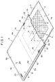
- a printing sheet 1 is a substantially rectangular sheet of about 200 microns in thickness made of a thermoplastic resin such as polyethylene resin.
- Image data 2 is formed with high precision in the form of relief of the order of submicrons in a substantially rectangular region, shown with diagonal hatching in Fig. 1, of the surface 1a of the printing sheet 1.
- a row of sprocket holes 3 is formed along each side, the left side and the right side, of the printing sheet 1; the two rows are parallel and the sprocket holes 3 are spaced at a fixed pitch.
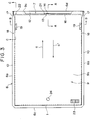
- a printing sheet jacket 6 is substantially rectangular and has the form of a flat bag with three sides 6a, 6b and 6c closed in a substantial C-shape and a printing sheet removal/insertion opening 7 provided at the fourth side 6d.
- This printing sheet jacket 6 can be simply manufactured by horizontally superposing a substantially rectangular base sheet 8 and cover sheet 9 of thickness approximately 200 microns made of a thermoplastic resin such as polyethylene resin or the like or PET resin sheet having its surface coated with about 5 to 40 ⁇ m of a readily thermally decomposing material (for example a nitrocellulose compound) and thermally sealing three of the sides 6a, 6b and 6c in a substantial C-shape of a predetermined width (thermally fusing together the base sheet 8 and the cover sheet 9 by heating them while pressing them together).
- a readily thermally decomposing material for example a nitrocellulose compound
- the left and right side edges of the printing sheet jacket 6 are formed as a left/right parallel pair of belt-shaped roller press portions 10 of a predetermined width.
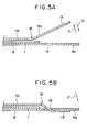
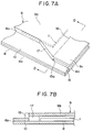
- the cover sheet 9 of the printing sheet jacket 6 has a horizontal ceiling portion 9b formed integrally atop a substantially C-shaped vertical portion 9a which projects vertically upward along the inside of the three edges 6a, 6b and 6c thermally sealed in a substantial C-shape, and a flat printing sheet accommodating space 11 of a height H 1 greater than the thickness T 1 of the printing sheet 1 is formed between the ceiling portion 9b of the cover sheet 9 and the base sheet 8.
- the printing sheet 1 is accommodated in the printing sheet accommodating space 11 with its front surface 1a facing upward and can be removed from and reinserted into the printing sheet accommodating space 11 through the printing sheet removal/insertion opening 7 in the direction of the arrows (a), a'.
- a cutaway 12 is formed from the central portion to the left and right side portions of the opening end 9c, which is the end portion of the cover sheet 9 at the printing sheet removal/insertion opening 7 end, and an opening/closing flap 13 is formed integrally with the cover sheet 9 in the central portion of the cutaway 12.
- this opening/closing flap 13 is passed through a slot-shaped opening/closing flap lock hole 14 formed in the central portion of the opening end 8a of the base sheet 8, and this blocks the printing sheet removal/insertion opening 7 of the printing sheet jacket 6 and locks in the printing sheet 1 (prevents the printing sheet 1 from coming out of the printing sheet jacket 6) sheathed inside the printing sheet jacket 6.
- a left/right parallel pair of slits 15 cut out of the opening end 9c of the cover sheet 9 are formed in the cover sheet 9 at the left and right sides of the printing sheet removal/insertion opening 7, and the opening end 9c of the cover sheet 9 can open and close easily across its entire width in the direction of the arrows b, b' along a crease 16 connecting the deepest portions 15a of the left/right slits 15.
- a left/right pair of taper portions 17 tapering off in the printing sheet insertion direction (the direction of the arrow a') for guiding printing sheet insertion are formed integrally at the left and right sides of the printing sheet removal/insertion opening 7 from the deepest portions 15a of the left/right slits 15 to the left/right sides of the vertical portion 9a.
- a left/right pair of jacket holding holes 18 passing vertically through the base sheet 8 and the cover sheet 9 are formed in the left/right pair of roller press portions 10 in locations in the vicinity of the printing sheet removal/insertion opening 7 of the printing sheet jacket 6.
- Misloading (mis-insertion) detection holes 21, 22 constituting objects of detection of misloading detecting means for detecting misloading (mis-insertion) of the printing sheet jacket 6 into a printing sheet making machine and a printing machine to be discussed hereinafter are formed in the vicinity of the printing sheet removal/insertion opening 7 of the printing sheet jacket 6 in left/right positions asymmetrical with respect to the left-right direction center of the printing sheet jacket 6.
- the misloading detection hole 21 is formed to one side of the opening/closing flap 13 and the misloading detection hole 22 is disposed above the centerline of one of the rows of sprocket holes 3 in the printing sheet 1.
- a bar code label 23 for identifying the type of the printing sheet 1 sheathed inside the printing sheet jacket 6 (identifying its type in terms of whether or not it is a new printing sheet and what image data 2 is engraved on it in what colors, etc) is affixed to the upper side of the cover sheet 9 of the printing sheet jacket 6.
- an observation hole 24 for identifying the above-mentioned type of the printing sheet 1 visually is provided in the cover sheet 9 of the printing sheet jacket 6.
- image data 2 such as a photograph or the like is engraved in the form of relief in the front surfaces 1a of 1 to 4 printing sheets 1.
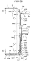
- the printing sheet making machine 27 is fitted with a jacket loading table 28 and a printing sheet feed and eject device 29 disposed thereon.
- a printing cylinder 30 Inside the printing sheet making machine 27 there are disposed a printing cylinder 30 and a laser block 34 which shines a laser beam CB emitted by a semiconductor laser 31 through a collimator lens 32 and an objective lens 33 onto the surface 1a of a printing sheet wound on the periphery of the cylinder 30.
- the laser block 34 is reciprocated in the axial direction of the cylinder 30 [perpendicular to the plane of the drawing of Fig. 8(B)].
- the printing machine 37 is provided with 1 to 4 jacket loading tables 38 and 1 to 4 printing sheet feed and eject devices 39 for loading, feeding and ejecting 1 to 4 printing sheet jackets 6, and inside the printing machine 37 there are disposed the same number of printing cylinders 40, pressure rollers 41 and ink units 45 comprising ink pans 42, ink rollers 43, and doctor blades 44, etc.
- Four colors of water-type ink 46 such as cyan, magenta, yellow and black are supplied color by color to the 4 ink pans 42.
- the printing machine 37 is provided with a cut paper tray 48 on which is stacked cut paper 47, the matter to be printed, and inside the printing machine 37 is mounted a cut paper circulating apparatus (not shown in the drawings) for circulating the cut paper 47 to the 1 to 4 pressure rollers 41 one after another.
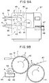
- Fig. 9(A) shows a printing machine provided with two jacket loading tables 38, two printing sheet feed and eject devices 39, two cylinders 40, two pressure rollers 41 and two ink units 45.
- a printing sheet jacket 6 in which an unengraved printing sheet 1 is sheathed is loaded horizontally in the direction of the arrow (a) onto the jacket loading table 28 of the printing sheet making machine 27.
- the printing sheet feed and eject device 29 automatically pulls the printing sheet 1 out from inside the printing sheet jacket 6 in the direction of the arrow (a) and winds the printing sheet 1 onto the periphery of the cylinder 30 inside the printing sheet making machine 27, as shown in Fig. 8(B).
- so-called direct engraving wherein the printing sheet 1 is rapidly rotated in the direction of the arrow c by the cylinder 30 while the semiconductor laser 31 shines a laser beam LB onto the surface 1a of the printing sheet 1 while the laser block 34 is reciprocated in the axial direction of the cylinder 30 and color by color image data 2 of a photograph or the like is thereby engraved directly with high precision in the form of relief of the order of submicrons in the surface 1a of the printing sheet 1, is carried out on 1 to 4 printing sheets 1 one after another.
- digital information representing an image such as a photograph is taken from a multimedia source such as a photograph scanner or a digital VTR and electronically edited in an image processing computer or the like, and digital information for each of four colors such as cyan, magenta, yellow and black is obtained.
- the 1 to 4 printing sheets 1 are then put through the printing sheet making machine one after another and based on this color by color four-color digital information color by color image data 2 for each of the four colors is then separately engraved on the 1 to 4 printing sheets 1.
- Each engraved printing sheet 1 is automatically removed from the periphery of the cylinder 30 in the direction of the arrow a' and reinserted into its printing sheet jacket 6 by the printing sheet feed and eject device 29, whereby the engraving step is finished.
- the printing sheet jacket 6 is then removed from the jacket loading table 28 in the direction of the arrow a' and loaded into the printing machine 37.
- the 1 to 4 printing sheet jackets 6 containing the engraved printing sheets 1 of the different colors engraved color by color in the engraving step are severally loaded horizontally in the direction of the arrow (a) onto the 1 to 4 jacket loading tables 38 of the printing machine 37.
- the printing sheet feed and eject devices 39 automatically pull the printing sheets 1 out of their printing sheet jackets 6 in the direction of the arrow (a) and automatically wind them onto the peripheries of the 1 to 4 cylinders 40 inside the printing machine 37, as shown in Fig. 9(B).
- Cut paper 47 from the cut paper tray 48 shown in Fig. 9(A) is circulated around the 1 to 4 pressure rollers 41 and printing of the kind illustrated in Fig. 9(B) is carried out.
- the pressure rollers 41 which rotate at high speed in the direction of the arrow f in synchrony with the cylinders 40, feed the cut paper 47 past the cylinders 40 at high speed while pressing it against the surfaces 1a of the printing sheets 1, and the color by color image data 2 of a photograph or the like on the printing sheets 1 prints a sequentially colored image 4 on the cut paper 47 at high speed.
- jacket loading tables 28 and 38, the printing sheet feed and eject devices 29 and 39, and the cylinders 30 and 40 of the printing sheet making machine 27 and the printing machine 37 are of identical construction.
- the jacket loading table 28, the printing sheet feed and eject device 29 and the cylinder 30 of the printing sheet making machine 27 will now be described with reference to Figs. 10 to 29.
- a table cover 51 is horizontally mounted on a horizontal jacket loading table 28 and a printing sheet jacket 6 is horizontally loaded into a horizontal jacket loading space 52 formed between these two onto the jacket loading table 28 in the direction of the arrow (a) with its printing sheet removal/insertion opening 7 end at the front.
- Left/right side guides 53 for horizontally guiding the left and right sides of the printing sheet jacket 6 are formed integrally with the table cover 51 at the left and right sides thereof.
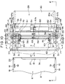
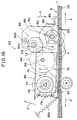
- the printing sheet feed and eject device 29 is mounted above the table cover 51 of the jacket loading table 28; this printing sheet feed and eject device 29 comprises left/right symmetrical pairs of jacket and printing sheet pulling in devices 55 and jacket holding devices 56, and is also provided with jacket central and side flap opening devices 57a and 57b.
- a drive shaft 58, a camshaft 59 and a sprocket shaft 60 are disposed horizontally crossing over the table cover 51 in the left-right direction and are mounted on a left/right pair of brackets 61.
- a motor 62 and a gear train 63 for reversibly rotationally driving the drive shaft 58 and a motor 64 and a gear train 65 for reversibly rotationally driving the camshaft 59 are mounted above the table cover 51.
- Three left/right pairs of cam mechanisms 66, 67 and 68, six cam mechanisms in total, are mounted at the left and right ends of the camshaft 59, and a cam mechanism 69 is mounted at the central portion of the camshaft 59.
- the left/right pairs of jacket and printing sheet pulling in devices 55 and jacket holding devices 56 and the jacket central and side flap opening devices 57a and 57b are driven by the motors 62 and 64, the gear trains 63 and 65, the drive shaft 58, the camshaft 59 and the cam mechanisms 66, 67, 68 and 69 in the manner described hereinafter.
- a number of sensors S 1 to S 8 constituting a controller for controlling the jacket and printing sheet pulling in devices 55, the jacket holding devices 56 and the jacket central and side flap opening devices 57a and 57b so that they operate sequentially based on predetermined sequences are provided.
- the sensors S 1 to S 6 each consist of a light emitting device LD and a light receiving device PD disposed so as to perform light detection vertically through the jacket loading table 28 and the table cover 51.
- the sensors S 7 and S 8 comprise photocouplers which perform detection on a pair of slit discs 70 mounted on the left and right ends of the camshaft 59.
- a left/right pair of jacket stoppers 71 are mounted on the left and right sides of the arrow (a) direction end of the jacket loading table 28.
- the left/right jacket and printing sheet pulling in devices 55 are constructed left/right symmetrically and are provided with a left/right pair of seesaw-style pivoting arms 76 each made up of first and second arms 73 and 74 mounted pivotally in the direction of the arrows h, h' on the left and right end portions of the drive shaft 58, which doubles as a supporting shaft for them, and limiter springs 75 consisting of tension springs or the like which pull the first and second arms 73 and 74 toward each other.
- a left/right pair of drive rollers 77 which are jacket pulling in means, are rotatably mounted via a left/right pair of horizontal roller shafts 78 on the left/right pair of second arms 74 on the arrow a' direction side of the drive shaft 58.
- the left/right pair of drive rollers 77 comprise high friction rollers such as rubber rollers and a left/right pair of torque limiters 77a are incorporated therein.
- a left/right pair of pinch rollers 79 are rotatably mounted via a horizontal roller shaft 80 on the underside of the jacket loading table 28 directly below and facing the pair of drive rollers 77.
- a left/right pair of long holes 81 are formed in the table cover 51 and in the jacket loading table 28 to allow the left/right pairs of drive rollers 77 and pinch rollers 79 to project therethrough.
- the left and right ends of the sprocket shaft 60 are rotatably attached to the left/right pair of first arms 73 on the direction (a) side of the drive shaft 58.
- a left/right pair of sprockets 82 which are printing sheet pulling in means, are mounted on the left and right ends of the sprocket shaft 60.
- a left/right pair of long holes 83 are formed in the table cover 81 and the jacket loading table 28 to allow the left/right pair of sprockets 82 to project therethrough.
- a left/right pair of cam mechanisms 66 which are control mechanisms, mounted on the left/right end portions of the camshaft 59, each comprise a cam 66a mounted on the camshaft 59, a driven roller 66b, which is a cam follower, rotatably mounted on the first arm 73, and a cam spring 66c, consisting of a tension spring or the like, which rotationally urges the first arm 73 in the direction of the arrow h and presses the driven roller 66b onto the upper portion of the periphery of the cam 66a.
- the first and second arms 73 and 74 are urged toward each other in the direction of the arrows h, h' by the limiter spring 75 and have their positions with respect to each other restricted by a stopper 87 disposed between them.
- the first arm 73 rotationally urged by the cam spring 66c in the direction of the arrow h about the camshaft 58, has its position restricted by being caused by a rubber cushion 88 to abut with the top of a stopper 89 mounted on the table cover 51.
- the rotational drive of the drive shaft 58 is transmitted to the roller shaft 78 and the sprockets 82 via the drive mechanism made up of the drive gears 84 and the driven gears 85 and 86, and the left right pairs of drive rollers 77 and sprockets 82 are thereby forward/reverse rotationally driven simultaneously.
- the cam angle 0° and 180° positions of the cam 66a are detected by the sensor S 7 .
- the drive rollers 77 and the sprockets 82 are simultaneously forward/reverse rotationally driven by the single drive shaft 58 via the drive mechanism made up of the drive gears 84 and the driven gears 85 and 86, the two types of actuator that are the drive rollers 77 and the sprockets 82 can be simultaneously forward/reverse rotationally driven by the single motor 62.
- a left/right pair of jacket holding devices 56 are of left/right symmetrical construction and comprise a left/right pair of vertical slider mounting plates 92 mounted on the table cover 51 and a left/right pair of sliders 95 mounted on side surfaces of these slider mounting plates 92 by way of a plurality of guide holes 93 and guide pins 94 in such a way that they can move vertically in the direction of the arrows i, i'.
- a left/right pair of holding pins 96 which are jacket holding means, are fixed to the undersides of the left/right pair of sliders 95 and project perpendicularly downward therefrom.
- a left/right pair of cam mechanisms 67 which are drive mechanisms for raising and lowering the left/right pair of holding pins 96 in the direction of the arrows i, i', are each made up of a cam 67a mounted on the camshaft 59, a cam driven roller 67b, which is a cam follower, rotatably mounted on the slider 95, and a cam spring 67c, consisting of a tension spring or the like, which urges the slider 95 upward in the arrow i direction and presses the cam driven roller 67b against the underside of the periphery of the cam 67a.
- a taper 96a is formed on the lower end of each of the left/right pair of holding pins 96. Holes 97 are formed in the table cover 51 and the jacket loading table 28 to allow the left/right pair of holding pins 96 to pass therethrough.
- the left/right cam mechanisms 67 cause the left/right pairs 96 of the left/right jacket holding devices 56 to ascend or descend in the direction of the arrows i, i'.
- the tapers 96a are provided on the lower ends of the left/right pair of holding pins 96, even if the printing sheet jacket 6 is slightly out of the above-mentioned fixed position, the guiding action of the tapers 96a serves to automatically bring the printing sheet jacket 6 into the fixed position as the holding pins 96 descend.
- This jacket central flap opening device 57a is a device for opening the flap of the central part of the opening end 9c of the cover sheet 9 of the printing sheet jacket 6.
- This jacket central flap opening device 57a has a vertical flap opening arm mounting plate 100 mounted on the central portion of the table cover 51, a flap opening arm 102 and a cam driven arm 103 mounted pivotally in the direction of the arrows j, j' on a side surface of the flap opening arm mounting plate 100 via a horizontal supporting shaft 101, and a central flap opening suction pad 104, which is central flap opening means, and a central pushing pin 105, which is central pushing means, mounted on the underside of the end portion of the flap opening arm 102 and projecting perpendicularly therefrom.
- the central cam mechanism 69 which is a control mechanism, mounted at the center of the camshaft 59, is made up of a cam 69a mounted on the camshaft 59, a cam driven roller 69b, which is a cam follower, rotatably mounted on the cam driven arm 103, and a cam spring 69c, consisting of a tension spring or the like, which at all times pushes the cam driven roller 69b against the periphery of the cam 69a.
- the flap opening arm 102 is mounted on the support shaft 101 in such a way that it can pivot in the direction of the arrows j, j', and the cam driven arm 103 is mounted on this flap opening arm 102 via a plurality of adjustment screws 106 in such a way that its length in the direction of the arrows k, k' is adjustable.
- Two holding suction pads 107 and 108 which are central holding means, are vertically mounted under the jacket loading table 28 in positions directly below the central flap opening suction pad 104 and the central pushing pin 105 respectively.
- the central flap opening suction pad 104 and the central holding suction pads 107 and 108 are constructed as vacuum suction-gripping means connected to a vacuum pump (not shown in the drawings).
- the flap opening arm 102 is caused to pivot up and down in the direction of the arrows b, b' by the cam driven roller 69b which is at all times pushed against the periphery of the cam 69c by the cam spring 69c and rolls along the periphery of the cam 69a.
- the central flap opening suction pad 104 and the central holding suction pads 107 and 108 are caused by suction from the vacuum pump to suction-grip the central portions of the upper side of the cover sheet 9 and the underside of the base sheet 8 respectively.
- the opening/closing flap 13 is reliably and easily pulled in the arrow b direction out of the opening/closing flap lock hole 14.
- the flap opening arm 102 returns a little in the arrow b' direction and returns the opening end 9c of the cover sheet 9 suction-gripped by the central flap opening suction pad 104 in the arrow b' direction a little to a predetermined opening stroke ⁇ 2 wherein the cover sheet 9 is unstressed, and the printing sheet removal/insertion opening 7 is held open to a predetermined extent.
- This jacket side flap opening device 57b is a device for opening the left and right side portions of the opening end 9c of the cover sheet 9 of the printing sheet jacket 6 and is of left/right symmetrical construction.
- the jacket side flap opening device 57b comprises a left/right pair of vertical flap opening arm mounting plates 111, a left/right pair of circular arcuate holes 112 formed in the left/right pair of flap opening arm mounting plates 111, a left/right pair of flap opening arms 114 mounted via left/right pairs of rollers 113 on side surfaces of the left/right pair of flap opening arm mounting plates 111 in such a way that they can move circularly along the left/right pair of circular arcuate holes 112 in the direction of the arrows n, n', a left/right pair of drive arms 116 mounted on the opposite side surfaces of the left/right pair of flap opening arm mounting plates 111 from the left/right pair of flap opening arms 114 at their upper ends via a left/right pair of support shafts 115 in such a way that they can pivot in the direction of the arrows o, o', and a left/right pair of side flap opening suction pads 117, which are side flap opening means, mounted perpendicularly on the underside
- the left/right pair of circular arcuate holes 112 are formed in circular arcs of radius of curvature R with the crease line 16 of the opening end 9c of the cover sheet 9 as a virtual center. Therefore, the left/right pair of flap opening arms 114, engaged with these circular arcuate holes 112 via the pairs of rollers 113, move circularly along these circular arcuate holes 112 in the direction of the arrows n, n' with the crease line of the opening end 9c of the cover sheet 9 of the printing sheet jacket 6 as a virtual center.
- a left/right pair of side cam mechanisms 68 which are control mechanisms, mounted at the left and right end portions of the camshaft 59, each comprise a cam 68a mounted on the camshaft 59, a cam driven roller 68b, which is a cam follower, rotatably mounted on the drive arm 116, and a cam spring 68c, consisting of a tension spring or the like, which at all times pushes the cam driven roller 68b against the periphery of the cam 68a.
- the lower ends of the left/right pair of drive arms 116 are linked to the left/right pair of flap opening arms 114 via link pins 119 mounted on the drive arms 116 and passing through openings 118 in the left/right pair of opening arm mounting plates 111 into linking holes 120 formed in the flap opening arms 114.
- a left/right pair of side holding suction pads 121 which are side holding means, are perpendicularly mounted underneath the jacket loading table 28 and directly below the left/right pair of side flap opening suction pads 117.
- the left/right pairs of side flap opening suction pads 117 and side holding suction pads 121 are constructed as vacuum suction-gripping means connected to a vacuum pump.
- each cam mechanism 68 when the cam 68a of each cam mechanism 68 is rotated in the direction of the arrow by the camshaft 59 from the cam angle 180° shown in Fig. 26 toward the cam angle 0°, the flap opening arm 114 is caused to reciprocate in the direction of the arrows n, n' via the drive arm 116 by the cam driven roller 68b which is at all times pressed against the periphery of the cam 68a by the cam spring 68c and rolls around the periphery of the cam 68a.
- the pair of rollers 113 of the opening arm 114 move circularly in the circular arcuate holes 112 in the direction of the arrows n, n' and the side flap opening suction pads 117 consequently move circularly in the direction of the arrows n, n' with the hereinafter discussed crease 16 of the cover sheet 9 of the printing sheet jacket 6 as a virtual center.
- the left/right pair of side flap opening suction pads 117 are pressed down in the arrow b' direction by the flap opening arms 114 onto the left and right side portions of the opening end 9c of the cover sheet 9 of the printing sheet jacket 6 loaded in the above-mentioned fixed position on the jacket loading table 28, and also the left/right side portions of the opening end 8a of the base sheet 8 of the printing sheet jacket 6 are pushed by the left/right pair of side flap opening suction pads 117 down onto the left/right pair of side holding suction pads 121.
- the left/right pair of side flap opening suction pads 117 and the left/right pair of side holding suction pads 121 are caused by the suction force of the vacuum pump to suction-grip the left and right side portions of the cover sheet 9 and the base sheet 8.
- the cams 66a to 69a of the cam mechanisms 66 to 69 are set to be at cam angle 0° before the start of printing sheet feeding.
- the motor 62 is driven to rotate forward and, a shown in Fig. 15, the rotation of the left/right pair of drive rollers 77 in the direction of the arrow automatically pulls the printing sheet jacket 6 into the jacket loading space 52 in the arrow (a) direction.
- the sensor S 5 detects the presence or otherwise of the misloading detection hole 21 formed in a left/right asymmetrical position in the printing sheet jacket 6, and top/bottom and front/rear misloading (mis-insertion) of the printing sheet jacket 6 can thereby be detected.
- the left/right pair of drive rollers 77 are immediately driven to rotate in reverse and automatically eject the printing sheet 6 in the arrow a' direction, or the fact that the printing sheet jacket 6 has been incorrectly loaded is made known to the operator by some kind of display or the like.
- the vacuum pump is activated and the motor 64 is driven to rotate in reverse to change the cam angle of the cams 66a to 69a of the cam mechanisms 66 to 69 from 180° to 0°.
- the opening end 9c of the cover sheet 9 is unforcedly and smoothly opened across its entire width about the crease 16, and the printing sheet removal/insertion opening 7 is opened across its entire width.
- the left/right pair of drive rollers 77 are withdrawn to above the printing sheet jacket 6.
- the left/right pair of holding pins 96 are inserted into the left/right pair of jacket holding holes 18 in the printing sheet jacket 6 and the printing sheet jacket 6 is thereby held in the above-mentioned fixed position.
- the left/right pair of sprockets 82 engage with the sprocket holes 3 in the left and right sides of the printing sheet 1 inside the printing sheet jacket 6.
- the motor 62 is again driven to rotate and, as shown in Fig. 16, the rotational force of the left/right pair of sprockets 82 in the direction of the arrow drives the sprocket holes 3 in the direction of the arrow and the printing sheet 1 is automatically pulled out from inside the printing sheet jacket 6 in the direction of the arrow (a).
- the sensor S 6 counts the number of sprocket holes 3 and the extent to which the printing sheet 1 has been pulled out in the arrow (a) direction is thereby detected. This sensor S 6 can also detect the misloading detection hole 22 in the printing sheet jacket 6.
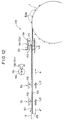
- the cylinder 30 When the printing sheet 1 has been pulled out of the printing sheet jacket 6 in the arrow (a) direction as far as a predetermined position, as shown in Figs. 11 and 12, the cylinder 30 is driven to rotate in the direction of the arrow and sprocket pins 30a provided around the peripheries of both ends of the cylinder 30 engage with the sprocket holes 3 in the left and right sides of the printing sheet 1 and, as shown by dotted lines in Figs. 11 and 12, the printing sheet 1 is automatically wound onto the periphery of the cylinder 30.
- the printing sheet 1 ends up completely out from inside the printing sheet jacket 6 and wound around the cylinder 30, as shown in Figs. 8(B) and 9(B).
- the cover sheet 9 is opened using the suction force of a vacuum pump connected to the central and side flap opening suction pads 104 and 117; by detecting the degree of vacuum created by the vacuum pump in the central and side flap opening suction pad 104 and 117 system with a pressure sensor, indirect detection of whether or not the cover sheet 9 has opened is carried out.
- the vacuum pump When the printing sheet 1 is to be ejected, the vacuum pump is operating, the cams 66a to 69a are set to cam angle 66a to 69a, the cover sheet 9 of the printing sheet jacket 6 held in the jacket loading space 52 is open, and the printing sheet removal/insertion opening 7 is standing by still open across its entire width.
- the printing sheet 1 is then automatically returned from the cylinder 30 into the printing sheet jacket 6 through the printing sheet removal/insertion opening 7 in the arrow a' direction.
- the motor 62 is driven to rotate in reverse and the left/right pair of sprockets 82 are thereby driven to rotate in reverse, the left/right pair of sprockets 82 drive the sprocket holes 3 in the left and right sides of the printing sheet 1, and the printing sheet 1 is automatically returned in the arrow a' direction into the printing sheet jacket 6.
- the speed of rotation of the left/right pair of sprockets 82 is made slightly higher than the speed at which the cylinder 30 reels out the printing sheet 1; this difference in speed is absorbed by the torque limiters 82a of the sprocket shaft 60, and thereby the printing sheet 1 can be returned in the arrow a' direction into the printing sheet jacket 6 without any slackness.
- the sensor S 5 detects this and the motor 62 is automatically stopped.
- the motor 64 is then driven to rotate forward and the cams 66a and 69a are set to the cam angle 180° whereby the left/right pair of drive rollers 77 are pushed down onto the printing sheet jacket 6 and the left/right pair of holding pins 96 and the sprockets 82 are withdrawn to above the printing sheet jacket 6.
- the motor 62 is then driven to rotate in reverse, and the printing sheet jacket 6 is automatically ejected from inside the jacket loading space 52 by a certain fixed amount in the arrow a' direction.
- the completion of the ejection of the printing sheet jacket 6 in the direction a' is detected by the sensor S 2 , and the motor 62 is automatically stopped.
- the motor 64 again sets the cams 66a to 69a to the cam angle 0° and thereby returns the apparatus to the initial printing sheet feeding state.
- the apparatus goes into a standby state, and even if the printing sheet jacket 6 is manually inserted in the arrow (a) direction again automatic printing sheet feeding will not be carried out.
- this electronic gravure printing system because the system can be operated without the operator touching the printing sheet 1 at all, the adhesion of dust and the like and the occurrence of scratching on the surface 1a of the printing sheet 1 on which the image data 2 is formed can be completely prevented and stable printed matter can be obtained. Also, by developing this system, an electronic gravure printing system which can be run unmanned can easily be realized.
- the devices for winding the printing sheet 1 onto the cylinders 30 and 40 of the printing sheet making machine 27 and the printing machine 37 discussed above are of identical construction.
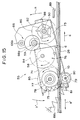
- the printing sheet winding device 251 of the printing sheet making machine 27 will now be described, with reference to Figs. 30 to 68.
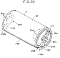
- a left/right pair of cylinder support frames 253 are perpendicularly mounted apart from each other on a chassis 252, and a cylinder 30 is disposed horizontally between these cylinder support frames 253.
- the axial direction (the left-right direction) ends of a horizontal shaft 30b fixed at the center of the cylinder 30 are rotatably mounted on the left/right pair of cylinder support frames 253 via a left/right pair of bearings (not shown in the drawings).
- the above-mentioned jacket loading table 28 is mounted horizontally between the left/right pair of cylinder support frames 253, and the forward end of the jacket loading table 28 in the arrow (a) direction is in the vicinity of the upper part of the cylinder 30.
- the cylinder drive mechanism 229 consists of a drive motor 230, which is cylinder rotational drive means, mounted on the chassis 252 and linked by a belt transmission mechanism 231 to one end of the shaft 30b.
- a rotary encoder 232 which is cylinder position detecting means, is directly coupled to the other end of the shaft 30b and is mounted on a side surface of one of the cylinder support frames 253.
- the arrangement is such that the cylinder 30 is freely forward/reverse rotationally driven in the direction of the arrows c, c' by the drive motor 230, detection of the position of the cylinder 30 in the direction of the arrows c, c' is performed by the rotary encoder 232, and the cylinder 30 can be stopped at designated positions.
- a row of sprocket pins 30a is provided at each end of the periphery of the cylinder 30; the sprocket pins 30a of both rows are spaced at the same pitch and are located in identical positions around the periphery of the cylinder 30.
- a printing sheet winding device 251 which will be further discussed hereinafter is mounted between the left/right pair of cylinder support frames 253.
- a printing sheet 1 automatically pulled out of a printing sheet jacket 6 loaded onto the jacket loading table 28 in the arrow (a) direction by the printing sheet feed and eject device 29 discussed above is automatically wound in the arrow c direction onto the periphery of the cylinder 30 by the two rows of sprocket pins 30a on the cylinder 30, as shown in Fig. 68, in a manner discussed hereinafter.
- a laser block transport mechanism 223 moves a laser block transport plate 224 on which the laser block 34 is mounted in the direction of the arrows s, s' by means of a feed screw 227 forward/reverse rotationally driven by a drive motor 226 mounted at one end of the feed screw 227 while guiding the laser block transport plate 224 between a pair of slide guides 225 parallel with the axis of the cylinder 30.
- a rotary encoder 228 which detects the position in the direction of the arrows s, s' of the laser block 34 is directly coupled to the other end of the feed screw.
- the printing sheet 1 is automatically unwound from the periphery of the cylinder 30 in the arrow c' direction and is automatically conveyed in the arrow a' direction into the printing sheet jacket 6.
- the printing sheet winding device 251 will now be described in detail.
- the two rows of sprocket pins 30a provided at a fixed pitch around the ends of the periphery of the cylinder 30 each consist of for example 12 sprocket pins 30a spaced at 30°.
- the arrangement is such that sprockets 30a of the two rows of sprockets 30a enter every third sprocket hole 3 of the two rows of sprocket holes 3 formed along the left and right sides of the printing sheet 1, and the printing sheet 1 is wound around the periphery of the cylinder 30 through an angle of 360° plus ⁇ .
- the pitch P 1 in the circumferential direction of the cylinder and the span P 2 in the axial direction of the cylinder of the two rows of sprocket pins 30a on the periphery of the cylinder 30 are made slightly larger (about 0.01 to 0.03mm) than the distance between every third sprocket hole 3 and the span between the two rows of sprocket holes 3, i.e. than the engaging pitch P 3 and the engaging span P 4 .
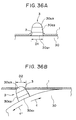
- each of the sprocket pins 30a has a cylindrical surface 30a 1 formed at its base portion, a tapered surface 30a 2 formed above the cylindrical surface 30a, and an R surface 30a 3 formed atop the cylindrical surface 30a 2 .
- the sprocket holes 3 are press fitted over the cylindrical surfaces 30a 1 of the sprocket pins 30a.
- the width through which the sprocket holes 3 along the side of the printing sheet 1 corresponding to the sprockets 30a disposed along a reference position P 5 at one end of the cylinder 30 are press fitted over those sprockets 30a is made large, and the width through which the sprocket holes 3 along the other side of the printing sheet 1 corresponding to the sprockets 30a disposed along a non-reference position P 6 at the other end of the cylinder 30 is made small.
- the jacket loading table 28 is disposed on a horizontal tangent of the top of the periphery of the cylinder 30, and the vertical position line connecting the axis of rotation of the cylinder 30 and the intersection of this tangent and the top of the cylinder 30 is set to be the press fitting position P 11 of the sprocket holes 3 with respect to the sprocket pins 30a.
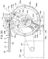
- a position approximately 15° behind this press fitting position P 11 in the arrow c' direction is set to be a reference position P 12 of the circumferential direction of the cylinder 30, and a position about 30° in front of the press fitting position P 11 in the arrow c' direction is set to be a printing sheet clamping position P 13 .
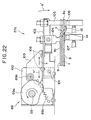
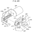
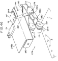
- a left/right pair of printing sheet pressing plates 256 which serve as both printing sheet lifting-off means and printing sheet pressing means, a left/right pair of printing sheet press fitting rollers 257 constituting printing sheet press fitting means, a printing sheet clamper 258, a left/right pair of locking pins 259 which constitute clamper control means, a magnet 260 for attracting the printing sheet clamper 258, and a printing sheet guide 261.
- the left/right pair of printing sheet pressing plates 256 are disposed left/right symmetrically at the inner sides of the left/right pair of cylinder support frames 253 in positions at the reference position P 12 over the two rows of sprocket pins 30a of the cylinder 30.
- a left/right pair of printing sheet pressing plate drive devices 264 which drive this left/right pair of printing sheet pressing plates 256 are mounted left/right symmetrically on the outer sides of the left/right pair of cylinder support frames 253.
- the printing sheet pressing plates 256 are made of plastic and each have an elastic twin-pronged arm 256a and a slot 256b open in the arrow (a) direction formed in their central portion. Base portions of the printing sheet pressing plates 256 pass through long holes 265 formed diagonally in the cylinder support frames 253 and project to the outer sides of the cylinder support frames 253 and are fixed to support plates 266 disposed on the outer sides of the cylinder support frames 253.
- the support plates 266 are each guided by a total of four guide rollers 267 mounted on the outer side of the respective cylinder support frame 253 so that the printing sheet pressing plates 256 move in the direction of the arrows c, c', which is diagonally up and down with respect to the position P 12 .
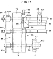
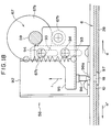
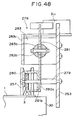
- the printing sheet pressing plate drive devices 264 each comprise a worm 270 linked by a coupling 269 to a drive motor 268 mounted on a bracket 268a, a worm wheel 271 meshing with the worm 270, a pinion 273 linked via an intermediate gear 272 to the worm wheel 271, a rack 274 fixed to the supporting plate 266 and meshing with the pinion 273, a shutter plate 275 fixed to the side surface of the rack 274, and a pair of sensors S 9 , S 10 , comprising photocouplers, which are switched ON and OFF by the shutter plate 275.
- the printing sheet pressing plates 256 are moved integrally with the supporting plates 266 by the drive motor 268 via the worms 270, the worm wheels 271, the intermediate gears, the pinions 273 and the racks 274 to the operating positions shown by solid lines in Figs. 30 and 44; the sensors S 9 detect the movement of the shutter plate 275, and the drive motor 268 is automatically stopped.
- the left/right pair of printing sheet press fitting rollers 257 are made of plastic, and each has a central circular groove 257a formed around the central portion of its periphery. These left/right pair of printing sheet press fitting rollers 257 are disposed left/right symmetrically inside the left/right pair of cylinder support frames 253 in positions at the press fitting position P 11 over the two rows of sprocket pins 30a of the cylinder 30.
- the left/right pair of printing sheet press fitting roller drive devices 278 which drive these left/right pair of printing sheet press fitting rollers 257 are mounted left/right symmetrically on the inner sides of the left/right pair of cylinder support frames 253.
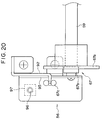
- Each printing sheet press fitting roller drive device 278 comprises a supporting shaft 279 horizontally mounted on the respective cylinder support frame 253; a supporting arm 280 rotatably mounted on the supporting shaft 279 and having the printing sheet press fitting roller 257 rotatably mounted on its end; a drive arm 281 pivotally mounted on the same supporting shaft 279; a limiter spring 282, consisting of a tension spring, fitted between the supporting arm 280 and the drive arm 281; a plunger solenoid 283, which is means for driving the drive cam 281 by means of a plunger 283a, mounted on the cylinder support frame 253; a stopper 285 of the drive arm 281; a return spring 284 of the plunger 283a, consisting of a tension spring; and a microswitch S 11 turned ON and OFF by the drive arm 281.
- the plunger 283a and the drive arm 281 are linked by a pin 283a, and the stopper 285 is formed integrally with the bracket 283c of the plunger solenoid
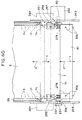
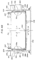
- the printing sheet clamper 258 is a belt-shaped plate made of a strongly magnetic material such as steel plate, and the overall length of this printing sheet clamper 258 is slightly greater than the overall length of the cylinder. Also, this printing sheet clamper 258 is curved in a circular arc along the periphery of the cylinder in a direction normal to its length direction. This printing sheet clamper 258 is pressed against and separated from the periphery of the cylinder while being held parallel with the axis of the cylinder by a left/right pair of printing sheet clamper support mechanisms 288.
- the left/right pair of printing sheet clamper support mechanisms 288 are left/right symmetrically mounted on the ends of the cylinder.
- the printing sheet clamper support mechanisms 288 each comprise a rotary support table 290 rotatably mounted via a bearing 289 on the left/right ends of the shaft 30b of the cylinder and a clamper support plate 293 mounted on the side of the rotary support table 290 slidably with respect to the rotary support table 290 in the direction of the arrows c 4 , c 4 ', which is a direction orthogonal to the axial direction of the cylinder, via a pair of screws/guide pins 291 and a pair of long holes 292.
- a left/right pair of bent pieces 258a are each bent into a right angle toward the center of the cylinder at the ends of the printing sheet clamper 258.
- a left/right pair of support pin mating holes 294 are formed in the ends of the left/right pair of bent pieces 258a in positions biased to one side in the circumferential direction of the cylinder from the center P 14 of the printing sheet clamper 258 in the circumferential direction of the cylinder.
- a left/right pair of support pin mating holes 295 formed in positions slightly biased in one direction from the above-mentioned center P 14 in the ends of the left/right symmetrical left/right pair of clamper support plates 293 and the left/right pair of support pin mating holes 294 in the printing sheet clamper 258 are pivotally linked to each other by a left/right pair of support pins 296.
- the ends of the printing sheet clamper 258 are supported by the left/right pair of clamper support plates 293 and this printing sheet clamper 258 is movable in the direction of the arrows c 4 , c 4 ', which is a direction orthogonal to the axial direction of the cylinder, while being held parallel to the cylinder, and this printing sheet clamper 258 can pivot with respect to the left/right pair of clamper support plates 293 about the left/right pair of support pins 296 in the direction of the arrows c 5 , c 5 ' shown in Figs. 57 and 58.
- a left/right pair of spring attachment plates 297 are left/right symmetrically fixed by fixing screws 298 to the side surfaces of the left/right pair of rotary support plates 290 in positions peripheral to the bearings 289 so as to lie across the left/right pair of clamper support plates 293.
- Left/right pairs of pressure springs 301 and 302, consisting of tension springs, four springs in total, are fitted between spring anchorages 299a and 299b formed on the left/right pair of spring attachment plates 297 and spring anchorages 300a and 300b formed respectively on the opposite end portions of the bent pieces 258 from the support pin mating holes 294 and side portions of the left/right pair of clamper support plates 293.
- the printing sheet clamper 258 is pivotally urged in the arrow c 5 direction with respect to the left/right pair of clamper support plates 293 about the left/right pair of support pins 296 by the left/right pair of pressure springs 301, and the printing sheet clamper 258 and the left/right pair of clamper support plates 293 are together strongly urged in the direction c 4 with respect to the left/right pair of rotary support plates 290 by the left/right pairs, four springs in total, of pressure springs 301 and 302.
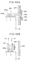
- a cam mechanism 305 constituting part of a clamper control mechanism for effecting clamping and unclamping of the printing sheet clamper 258 will be described.
- This cam mechanism 305 is made up of a left/right pair of concentric circular cams 306 fixed with screws to the ends of the cylinder around the vicinity of the periphery thereof, and left/right pairs of cam follower rollers 307, 308, consisting of bearings, rotatably mounted on the inner sides of the left/right pair of bent pieces 258 of the printing sheet clamper 258 in positions on opposite sides of the center P 14 in the circumferential direction of the cylinder.
- the left/right pairs of cam follower rollers 307 and 308 are pressed in the arrow c 4 direction against circular peripheral surfaces 306a, concentric with the cylinder, of the left/right pair of cams 306 by the left/right pairs of springs 301 and 302.
- a left/right pair of concave portions 306b into which the left/right pairs of cam follower rollers 307, 308 can descend simultaneously are formed in parts of the peripheral surfaces 306a of the left/right pair of cams 306.
- a fixed position lock mechanism 311 constituting another part of the printing sheet clamper control mechanism, for locking and unlocking the left/right pair of printing sheet clamper support mechanisms 288 in the printing sheet clamping position P 13 shown in Figs. 30 to 33, will be described.
- This fixed position lock mechanism 311 is made up of a left/right pair of slots 312 formed in the opposite ends of the left/right pair of rotary support plates 290 from the printing sheet clamper 258 and a left/right pair of locking pins 259 free to enter and exit this left/right pair of slots 312 in the direction of the arrows c 6 , c 6 ', parallel to the axis of the cylinder.
- Each lock pin drive mechanism 315 is mounted left/right symmetrically on the printing sheet clamping position P 13 on the outer sides of the left/right pair of cylinder support frames 253.
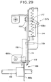
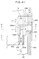
- Each lock pin drive mechanism 315 is made up of a locking pin guide 317 which guides the respective locking pin 259 in and out through a through hole 316 formed in the respective cylinder support frame 253 in the direction of the arrows c 6 , c 6 '; a feed screw 318 disposed coaxially with the lock pin 259 at the opposite end of the lock pin 259 from the cylinder; a drive motor 320, mounted on a bracket 319, which moves the feed screw 318 in the direction of the arrows c 6 , c 6 '; a return spring 321, consisting of a compression spring, which at all times pushes the lock pin 259 against the end of the feed screw 318 in the arrow c 6 ' direction; a shutter plate 323, fitted on the feed screw 318 side end portion of the lock pin 259 and guided by a
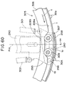
- a magnet 260 is recessed in the periphery of the cylinder in a roughly central position P 15 in the axial direction of the cylinder, whereby the roughly central portion in the length direction of the printing sheet clamper 258 pressed against the periphery of the cylinder in the printing sheet clamping position P 13 is pulled against the periphery of the cylinder by magnetic attraction.
- the printing sheet guide 261 is mounted on the chassis 252 in parallel with the cylinder and is below the arrow c' direction side vicinity of the printing sheet clamper 258 when the printing sheet clamper 258 is in position in the printing sheet clamping position P 13 .
- a printing sheet jacket 6 is loaded onto the jacket loading table 28 of the printing sheet feed and eject device 29 shown in Figs. 10 to 12, and when the sensor S 2 detects the printing sheet jacket 6 the automatic winding of the printing sheet 1 onto the periphery of the cylinder begins.
- the cylinder is driven in the direction of the arrow c by the cylinder drive mechanism 229, and, based on detection of the position of the cylinder by the rotary encoder 232, the left/right pair of printing sheet clamper support mechanisms 288 are stopped in the printing sheet clamping position P 13 .
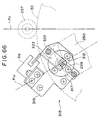
- the left/right pair of lock pins 259 are driven in the direction of the arrow c 6 by the left/right pair of lock pin drive mechanisms 315 shown in Figs. 63 to 66, and, as shown in Figs. 55 and 56, the left/right pair of lock pins 259 are inserted in the arrow c 6 direction into the left/right pair of slots 312 in the left/right pair of rotary support plates 290.
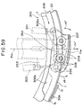
- the left/right pairs of cam follower rollers 307, 308 of the left/right pair of cam mechanisms 305 are pushed up from the concave portions 306b of the left/right pair of cams 306 onto the outer peripheral surfaces 306a, and, as shown in Figs. 30 and 59 with broken lines, the printing sheet clamper 258 is separated from the periphery of the cylinder in the arrow c 4 ' direction against the resistance of the left/right pairs of pressure springs 301, 302 while remaining parallel to the cylinder, and the printing sheet clamper 258 is thereby unclamped.
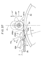
- first pins 30A which are a left/right pair of reference pins among the two rows of sprocket pins 30a on the periphery of the cylinder 30, are brought into the reference position P 12 , as shown in Fig. 37 with broken lines, and the cylinder is stopped.
- the automatic pulling in of the printing sheet jacket 6 in the direction of the arrow (a) to the above-mentioned fixed position and the automatic pulling out of the printing sheet 1 in the direction of the arrow (a) from inside the printing sheet jacket 6 are started by the printing sheet feed and eject device 29, shown in Figs. 10 to 12, and, as shown in Figs. 30 and 37, the leading end of the printing sheet 1 is fed roughly tangentially to the cylinder in the direction of the arrow (a) to the press fitting position P 11 of the cylinder.
- the sensor S 6 of the printing sheet feed and eject device 29 counts the sprocket holes 3 of the printing sheet 1 being fed in the direction of the arrow (a) and thereby detects the extent to which the printing sheet 1 has been pulled out in the direction of the arrow (a).
- the left/right pair of first pins 30A of the cylinder start to move from the reference position P 12 toward the press fitting position P 11 .
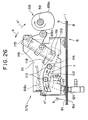
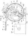
- the left/right pair of printing sheet pressing plate drive devices 264 and the left/right pair of printing sheet press fitting roller drive devices 278 shown in Figs. 43 to 45 and 46 to 48 lower the left/right pair of printing sheet pressing plates 256 and the left/right pair of printing sheet press fitting rollers 257 respectively from the non-operating positions and non-pressing positions shown with broken lines in Fig. 37 into the operating positions and pressing positions shown with solid lines in Fig. 37 in the direction of the arrow c 1 and the direction of the arrow c 3 .
- the twin-pronged arms 256a of the left/right pair of printing sheet pressing plates 256 having the slots 256b in their central portions, press the leading end of the printing sheet 1 down elastically in the direction of the arrow c 1 onto the periphery of the cylinder 30 on both sides of each of the left/right pair of first pins 30A.
- the left/right pair of printing sheet press fitting rollers 257 having the circular grooves 257a around their central portions, elastically press the leading end of the printing sheet 1 in the direction of the arrow c 3 onto the periphery of the cylinder 30 on both sides of the locuses of movement of the two rows of sprocket pins 30a on the cylinder.
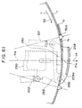
- the cylinder continues to rotate at low speed, and by being pulled in the direction of the arrow c by the left/right pair of first pins 30A the printing sheet 1 is automatically pulled out of the printing sheet jacket 6, the sprocket pins 30a disposed in two rows on the cylinder are inserted two by two into the sprocket holes 3 formed in two rows in the printing sheet 1, the two rows of sprocket holes 3 are firmly press fitted by the left/right pair of printing sheet press fitting rollers 257 onto the two rows of sprocket pins 30a down to the cylindrical surfaces 30a 1 at the bases thereof shown in Fig. 36(A), and the printing sheet 1 is thereby automatically wound onto the periphery of the cylinder 30.
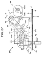
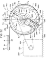
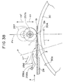
- the end 1b of the printing sheet 1 is guided by the printing sheet guide 261 so that it smoothly passes through the gap between the printing sheet clamper 258 and the periphery of the cylinder 30.
- the printing sheet clamper 258 strongly presses the trailing end 1c of the printing sheet 1 onto the leading end 1b and onto the periphery of the cylinder 30 in the direction of the arrow c 4 , and the leading end 1b and the trailing end 1c of the printing sheet 1 are thereby simultaneously clamped strongly onto the periphery of the cylinder 30.
- the positions of the concave portions 306b of the cams 306 are set so that this action occurs before the leading end of the printing sheet 1 wound in the direction of the arrow c on the periphery of the cylinder 30 reaches the printing sheet clamper 258.
- the magnet 260 recessed in the periphery of the cylinder 30 attracts and strongly holds the roughly central portion, in the length direction, of the printing sheet clamper 258.
- the left/right pair of printing sheet press fitting rollers 257 are raised in the direction of the arrow c 3 ' to their non-operating positions and, as shown in Fig. 56 by broken lines, the left/right pair of lock pins 259 are withdrawn in the direction of the arrow c 5 ' from the left/right pair of slots 312 in the left/right pair of rotary support plates 290 and the rotary support plates 290 are thereby unlocked from their fixed positions.
- the engraving step described hereinbefore is begun: the cylinder is rotated at high speed in the direction of the arrow c, and engraving of image data 2 of a photograph or the like onto the surface 1a of the printing sheet 1 is carried out.
- the printing sheet clamper 258 is rotated at high speed integrally with the cylinder while still clamping the printing sheet 1, and a phenomenon occurs wherein centrifugal force created by the high speed rotation causes the roughly central portion in the length direction of the printing sheet clamper 258 to float up from the periphery of the cylinder 30 in the direction of the arrow c 4 ' into a circular arc shape and the clamping force on the printing sheet 1 decreases.
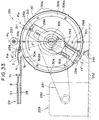
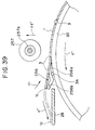
- the left/right pair of printing sheet pressing plates 256 are lowered in the direction of the arrow c 1 to their operating positions, and these printing sheet pressing plates 256 push the printing sheet 1 elastically onto the periphery of the cylinder 30 from above.
- the cylinder is rotated reversely in the direction of the arrow c' and the printing sheet 1 is automatically unwound from the cylinder starting from its trailing end 1c by the left/right pair of printing sheet pressing plates 256.
- the printing sheet 1 is lifted up from the bases of the sprocket pins 30a on the cylinder by the twin-pronged arms 256a of the left/right pair of printing sheet pressing plates 256, and the sprocket holes 3 of the printing sheet 1 are sequentially automatically wound off the two rows of sprocket pins 30a on the cylinder.
- the printing sheet 1 is guided by the left/right pair of printing sheet pressing plates 256 and automatically inserted in the direction of the arrow a' into the printing sheet jacket 6 on the jacket loading table 28.
- the pitch P 1 and the span P 2 of the two rows of sprocket pins 30a on the periphery of the cylinder 30 are approximately 0.01 to 0.03mm larger than the engaging pitch P 3 and the engaging span P 4 of the two rows of sprocket holes 3 in the printing sheet 1, when the two rows of sprocket holes 3 in the printing sheet 1 are press fitted onto the two rows of sprocket pins 30a on the cylinder and the printing sheet 1 is wound on the periphery of the cylinder 30, as shown in Fig.
- the printing sheet 1 automatically wound onto the periphery of the cylinder 30 can be positioned with high accuracy in both the circumferential direction of the cylinder referenced by the reference position P 12 and the axial direction of the cylinder referenced by the reference position P 12 .
- the printing sheet 1 automatically wound onto the periphery of the cylinder 30 is given tensions between the sprocket pins 30a in the X and Y directions that are the axial and circumferential directions of the cylinder, absolutely no slippage or wrinkling of the printing sheet 1 occurs.
- each sprocket pin 3a is formed with a cylindrical surface 30a 1 at the base, a taper surface 30a 2 above that and an R surface 30a 3 above that, as shown in Fig. 36(A) the press fitted sprocket holes 3 of the printing sheet 1 can be positioned stably and with high accuracy and yet as shown in Fig.
- the printing sheet feed and eject device of the printing sheet making and printing system of the present invention described above provides the following kinds of benefits:
- the invention facilitates development toward a completely automatic electronic gravure printing system which can be run unmanned.
- the chain of operations following the loading of the printing sheet jacket onto the jacket loading table consisting of the automatic pulling in of the printing sheet jacket, the automatic opening of the printing sheet jacket and the automatic pulling out of the printing sheet from inside the printing sheet jacket, can be systematically carried out in correct sequence.
- the jacket pulling in means is provided with a left/right pair of roller press portions formed at the left and right sides of the printing sheet jacket and a left/right pair of drive rollers which are pressed onto these roller press portions, by forward and reverse rotation of the left/right pair of drive rollers pressed onto the left/right pair of roller press portions the automatic pulling in and automatic ejection of the printing sheet jacket on the jacket loading table can be carried out accurately and easily.
- the flap opening means is provided with suction-gripping means for suction-gripping and opening the printing sheet removal/insertion opening end of the printing sheet jacket, the printing sheet removal/insertion opening end of the printing sheet jacket can be suction-gripped and accurately and easily opened by this suction-gripping means.
- the printing sheet pulling out means is provided with sprocket holes spaced at a fixed pitch along the left and right sides of the printing sheet and a left/right pair of sprockets which are engaged with the sprocket holes through a left/right pair of sprocket access holes formed in the printing sheet jacket, by forward and reverse rotation of the left/right pair of sprockets engaged with the sprocket holes in the left and right sides of the printing sheet through the left/right pair of sprocket access holes in the printing sheet jacket automatic pulling out of the printing sheet from the printing sheet jacket and automatic reinsertion of the printing sheet into the printing sheet jacket can be carried out accurately and easily.
- the structure is simple and the operation is reliable, and the operations of winding and unwinding the printing sheet onto and off the cylinder can be carried out stably.
- detecting means for detecting the extent to which the printing sheet has been pulled out of the printing sheet jacket by counting the sprocket holes in the printing sheet and cylinder rotational drive means and cylinder position detecting means for setting the sprocket pins of the sprocket printing sheet on the cylinder to a reference position and based on a signal from the detecting means rotating the cylinder and thereby inserting the sprocket pins into the first sprocket holes of the sprocket holes and on completion of the winding of the printing sheet which accompanies the rotation of the cylinder through a predetermined angle stopping the cylinder in a printing sheet clamping position, the chain of operations comprising the automatic winding and clamping of the printing sheet onto the cylinder can at all times by performed accurately and reliably.
- the two rows of sprocket holes are press fitted onto the two rows of sprocket pins as far as the base portions thereof; at this time, because the pitch in the circumferential direction of the cylinder and the span in the axial direction of the cylinder of the two rows of sprocket pins are made slightly greater than the engaging pitch and the engaging span of the two rows of sprocket holes with respect to the sprocket pins, positioning of the printing sheet on the cylinder can be performed with high accuracy so that no slippage or wrinkling of the printing sheet occurs whatsoever.
- the width through which the sprocket holes along the side of the printing sheet corresponding to the sprocket pins disposed along an axial reference position at one end of the cylinder are press fitted onto those sprocket pins is made large and the width through which the sprocket holes on the other side of the printing sheet corresponding to the sprocket pins disposed along a non-reference position at the other end of the cylinder are press fitted onto those sprocket pins is made small, the printing sheet wound on the cylinder can be positioned with high accuracy with respect to the axial direction reference position on the cylinder and the interchangeability of the printing sheet with respect to the cylinder is further raised.
- each of the sprocket pins on the cylinder has a cylindrical surface formed at its base, a tapered surface formed above that and an R surface formed atop the tapered surface, notwithstanding that the printing sheet can be positioned with high accuracy with respect to the cylinder, the insertion and removal of the sprocket pins on the cylinder into and out of the sprocket holes in the printing sheet can be performed smoothly.
- the left/right pair of printing sheet pressing means consist of printing sheet press fitting rollers, having central circular grooves, which push the printing sheet onto the periphery of the cylinder on the left and right sides of the sprocket pins, the two rows of sprocket holes of the printing sheet can be smoothly press fitted onto the two rows of sprocket pins on the cylinder as far as the bases thereof.
- the two rows of sprocket pins on the ends of the periphery of the cylinder are made to enter the two rows of sprocket holes formed in the printing sheet two by two and the printing sheet is thereby automatically pulled out of the printing sheet jacket and wound onto the periphery of the cylinder.
- At least the trailing end of the printing sheet wound on the cylinder is clamped onto a portion of the periphery of the cylinder by a printing sheet clamper mounted parallel with the axial direction of the cylinder.
- the printing sheet When the printing sheet is automatically wound onto the periphery of the cylinder, because after the printing sheet is wound onto the periphery of the cylinder by the two rows of sprocket pins on the cylinder being sequentially inserted into the two rows of sprocket holes in the printing sheet at least the trailing end of the printing sheet is clamped by the printing sheet clamper, the printing sheet can be wound onto the cylinder while being positioned thereon with high accuracy, and slippage and wrinkling of the printing sheet does not occur.
- pressure springs mounted in the left/right pair of printing sheet clamper support mechanisms which urge the printing sheet clamper against the periphery of the cylinder, a cam mechanism disposed around the peripheries of the ends of the cylinder which separates the printing sheet clamper from the periphery of the cylinder against the resistance of the pressure springs, and a fixed position lock mechanism which locks and unlocks the left/right pair of printing sheet clamper support mechanisms in a fixed position, clamping and unclamping of the printing sheet can be carried out simply and reliably.
- the left/right pair of printing sheet clamper support mechanisms are provided with a left/right pair of rotary support plates rotatably mounted on the periphery of the shaft of the cylinder at the ends of the cylinder which are locked and unlocked by the fixed position lock mechanism and a left/right pair of clamper support plates which support the ends of the printing sheet clamper and are supported slidably in a direction normal to the axial direction of the cylinder by the left/right pair of rotary support plates and are urged to slide in one direction by the pressure springs, when the printing sheet clamper is being clamped and unclamped the left/right pair of clamper support plates which slide with respect to the left/right pair of rotary support plates in a direction normal to the axial direction of the cylinder enable the printing sheet clamper to move in parallel with the cylinder. As a result, especially during clamping, the printing sheet clamper does not cause any slippage or wrinkling of the printing sheet.
- a printing sheet guide which guides the leading end of the printing sheet between the cylinder and the printing sheet clamper during winding of the printing sheet onto the periphery of the cylinder, the leading end of the printing sheet can be reliably guided between the printing sheet clamper and the cylinder during winding of the printing sheet onto the periphery of the cylinder and winding of the printing sheet and clamping of the wound printing sheet can be carried out smoothly.
- the two rows of sprocket pins on the ends of the periphery of the cylinder are made to enter the two rows of sprocket holes formed in the printing sheet two by two and the printing sheet is thereby automatically pulled out of the printing sheet jacket and wound onto the periphery of the cylinder.
- At least the trailing end of the printing sheet wound on the cylinder is clamped onto a portion of the periphery of the cylinder by a printing sheet clamper mounted parallel with the axial direction of the cylinder; because the roughly central portion, in the length direction, of the printing sheet clamper is attracted and held by a magnet recessed in the periphery of the cylinder, the printing sheet wound on the periphery of the cylinder can be clamped onto the periphery of the cylinder with good stability.
- the roughly central portion, in the length direction, of the printing sheet clamper is attracted and held by a magnet recessed in the periphery of the cylinder, the roughly central portion in the length direction of the printing sheet clamper floating off the periphery of the cylinder due to centrifugal force during high speed rotation of the cylinder during engraving or printing, and consequent reduction in the clamping force on the printing sheet, can be completely prevented from being a problem. As a result, high precision engraving and printing can be carried out stably.
- a cam mechanism which during unclamping of the printing sheet clamper causes the printing sheet clamper to undergo a pivoting motion wherein the ends of the printing sheet clamper in the cylinder circumferential direction pull away from the periphery of the cylinder alternately, even though when clamped the printing sheet clamper has its roughly central portion held against the periphery of the cylinder by the magnet, during unclamping the levering action of the pivoting motion of the printing sheet clamper enables the printing sheet clamper to easily separate from the magnet and unclamping of the printing sheet clamper can consequently be performed easily.
- the left/right pair of printing sheet clamper support mechanisms are provided with a left/right pair of rotary support plates rotatably mounted on the shaft of the cylinder at the ends of the cylinder, a left/right pair of clamper support plates mounted on these left/right pair of rotary support plates slidably in a direction normal to the axial direction of the cylinder, a left/right pair of support pins which at both ends of the printing sheet clamper pivotally support one side of the printing sheet clamper on the left/right pair of clamper support plates, pressure springs which pivotally urge the printing sheet clamper about the left/right pair of support pins and press the printing sheet clamper against the periphery of the cylinder, and pressure springs which urge and press the whole printing sheet clamper against the periphery of the cylinder by urging the left/right pair of clamper support plates to slide with respect to the left/right pair of rotary support plates, and because the cam mechanism is provided with cams formed on the ends of the cylinder and left/right pairs of cam follower rollers,
- the printing sheet jacket of the invention constructed as described above provides the following kinds of benefits:
- a printing sheet is removably sheathed in a substantially rectangular printing sheet jacket having three sides closed and a printing sheet removal/insertion opening provided at the fourth side and all the handling of the printing sheet involved in the feeding and ejection of the printing sheet to and from the cylinder of a printing sheet making machine and the feeding and ejection of the printing sheet to and from the cylinder of a printing machine, from start to finish, can be done with the printing sheet sheathed in the printing sheet jacket, the adhesion of dust and the like and the occurrence of scratching on the surface of the printing sheet can be completely prevented. As a result, the printing sheet can be handled safely and easily, and stable printed matter with no color blurring or scumming or the like can be obtained.
- the printing sheet can be handled sheathed inside a printing sheet jacket, a completely automated electronic gravure printing system or the like which can be run unmanned can easily be developed.
- a printing sheet accommodating space having a height greater than the thickness of the printing sheet is formed between the base sheet and the cover sheet by the cover sheet being provided with a vertical portion formed along the inner sides of the three closed sides of the printing sheet jacket, removal and reinsertion of the printing sheet from and into the printing sheet accommodating space inside the printing sheet jacket can be carried out smoothly.
- the printing sheet removal/insertion opening is provided with an opening/closing flap, the printing sheet will not readily accidentally fall out of the printing sheet jacket while the printing sheet jacket is being handled.
- the opening/closing flap is formed integrally with the opening end of the cover sheet and an opening/closing flap lock hole through which the opening/closing flap is passed to lock it is formed in the base sheet, the opening/closing flap can be reliably locked and the printing sheet is completely prevented from accidentally flying out of the printing sheet jacket while the printing sheet jacket is being handled.
- the opening end of the cover sheet can be easily opened and closed across its entire width and the printing sheet can be easily removed and inserted through the printing sheet removal/insertion opening.
- taper portions tapering off in the printing sheet insertion direction for guiding printing sheet insertion are formed in the vertical portion of the cover sheet at the left and right sides of the printing sheet removal/insertion opening, when the printing sheet is being inserted into the printing sheet jacket the taper portions guide the printing sheet and the printing sheet can be inserted smoothly.
- sprocket holes spaced at a fixed pitch are formed along the left and right sides of the printing sheet and a left/right pair of sprocket access holes which expose some of the sprocket holes are formed at the left and right sides of the printing sheet jacket, feeding and ejection of the printing sheet to and from a printing sheet making machine or a printing machine can be carried out automatically by sprockets.
- misloading of the printing sheet jacket into a printing sheet making machine or a printing machine can be prevented, and the printing sheet can be easily loaded to the cylinders of these machines.
Description
Claims (35)
- A printing sheet making apparatus for making an engraved printing sheet (1), comprising:a cylinder (30) for receiving a printing sheet (1) made of resin;engraving means (34) for engraving relief onto the printing sheet (1) on the cylinder (30) with a laser beam; characterised in that:the printing sheet (1) is sheathed in a jacket (6) and the apparatus further comprises:pulling out means (39) for pulling the printing sheet (1) out of the jacket (6); andwinding means for winding the printing sheet pulled out of the jacket (6) onto the cylinder (30).
- A printing apparatus for printing an image from an engraved printing sheet (1) onto matter to be printed, comprising:a cylinder (40) for receiving an engraved resin printing sheet (1);printing means (41,43) for carrying out printing by rotationally driving the cylinder (40) and applying ink to the printing sheet (1) wound on the cylinder (40); characterised in thatthe printing sheet (1) is sheathed in a jacket (6) and the apparatus further comprises:pulling out means (39) for pulling the engraved resin printing sheet (1) out of the jacket (6); andwinding means for winding the printing sheet (1) pulled out of the jacket (6) onto the cylinder (40).
- Apparatus according to claim 1 or 2, further comprising:peeling means for peeling the engraved printing sheet off the cylinder; andinserting means for inserting the peeled printing sheet into the jacket.
- Apparatus according to claim 1, 2 or 3,further comprising a jacket loading table (28) onto which the jacket is loaded,
wherein the pulling out means comprises:jacket moving means for moving the jacket from the loaded position to a predetermined position;flap opening means for opening a flap (13) provided on the jacket (6) moved to the predetermined position; andprinting sheet removing means for removing the printing sheet (1) from the jacket (6) whose flap (13) has been opened. - Apparatus according to claim 4, wherein the jacket moving means comprises:a roller press portion disposed on the jacket along the travelling path thereof; anda drive roller (77) which is pressed onto the roller press portion.
- Apparatus according to claim 4 or 5, wherein the printing sheet removing means comprises:a sprocket (82) which is engaged through a sprocket access hole (19,20) formed in the jacket (6) with sprocket holes (3) provided in the printing sheet (1).
- Apparatus according to claim 4, 5 or 6, wherein:the flap opening means (104) comprises suction-gripping means (104) for suction-gripping and opening the flap (13).
- Apparatus according to any one of the preceding claims, wherein:sprocket holes (3) are provided in the printing sheet (1), spaced at a predetermined pitch along the direction in which the printing sheet (1) is conveyed; andthe winding means comprises a plurality of sprocket pins (30a) disposed on the cylinder (30) which engage with the sprocket holes (3) and uses these sprocket pins (30a) to wind the printing sheet (1) onto the cylinder (30).
- Apparatus according to claim 8, wherein:the pitch of the sprocket pins (30a) is slightly greater than the pitch of the sprocket holes (3) provided in the printing sheet (1).
- Apparatus according to claim 8 or 9, wherein:the sprocket holes (3) are provided in the vicinities of one side and another side of the printing sheet (1), spaced at a fixed pitch along the direction in which the printing sheet (1) is conveyed; andthe winding means uses two rows of the sprocket pins (30a) which severally engage with two rows of the sprocket holes (3) to wind the printing sheet (1) onto the cylinder (30).
- Apparatus according to claim 10, wherein:the span of the two rows of sprocket pins (30a) is slightly greater than the span of the two rows of sprocket holes (3) provided in the printing sheet (1).
- Apparatus according to claim 8, 9, 10 or 11, further comprising:press fitting means for press fitting the printing sheet (1) onto the sprocket pins (30a) as far as the bases thereof by pressing the printing sheet (1) in the vicinity of the sprocket holes (3) onto the periphery of the cylinder (30) during winding of the printing sheet (1) onto the periphery of the cylinder (30).
- Apparatus according to claim 12, wherein:the press fitting means is a printing sheet press fitting roller (257) having a groove portion to accommodate the sprocket pins (30a) and a pressing portion which presses on the printing sheet (1) on both sides of the sprocket pins (30a).
- Apparatus according to any one of claims 8 to 13, wherein:the sprocket pins (30a) each comprise a cylindrical portion, a taper portion formed atop the cylindrical portion, and a spherical portion formed atop the taper portion.
- Apparatus according to any one of claims 8 to 14, further comprising:a printing sheet clamper (258) for clamping at least the trailing end portion of the printing sheet (1) wound on the cylinder (30) onto the periphery of the cylinder (30).
- Apparatus according to claim 15, further comprising:a printing sheet clamper support mechanism (288) mounted on the cylinder (30) rotatably about the axis thereof for supporting the printing sheet clamper (258) rotatably about the axis of the cylinder (30); anda printing sheet clamper control mechanism for controlling the clamping and unclamping of the printing sheet clamper (258) with respect to the periphery of the cylinder (30) by the cylinder (30) being rotated with the printing sheet clamper support mechanism (288) locked in a predetermined angular position with respect to the cylinder (30).
- Apparatus according to claim 16, wherein the printing sheet clamper control mechanism comprises:a spring (301) attached to the printing sheet clamper support mechanism (288) for urging the printing sheet clamper (258) to press against the periphery of the cylinder (30);a cam mechanism (305) for separating the printing sheet clamper (258) from the periphery of the cylinder (30) against the resistance of the spring; anda fixed position locking mechanism (311) for locking the printing sheet clamper support mechanism (288) in a predetermined angular position with respect to the cylinder (30).
- Apparatus according to claim 17, wherein the printing sheet clamper support mechanism comprises:a rotary support plate, mounted on the cylinder (30) rotatably with respect thereto about the axis thereof, which is locked and unlocked by the fixed position locking mechanism (311); anda clamper support plate mounted on the rotary support plate slidably in a direction normal to the axis of the cylinder (30) and urged by the spring in one direction normal to the axis of the cylinder (30).
- Apparatus according to claim 15, 16, 17 or 18, further comprising:a printing sheet guide which guides the leading end portion of the printing sheet between the cylinder (30) and the printing sheet clamper (258) when the printing sheet is being wound onto the periphery of the cylinder (30).
- Apparatus according to any one of claims 15 to 19, further comprising:detecting means for detecting the extent to which the printing sheet has been pulled out of the jacket (6) by counting the number of sprocket holes (3) in the printing sheet (1) pulled out of the jacket (6); andcylinder rotational drive means for with one of the sprocket pins (30a) as a reference pin rotating the cylinder (30) based on an output signal from the detecting means and inserting the reference pin into a first sprocket hole (3) in the printing sheet (1) and rotating the cylinder (30) through a predetermined angle and winding the printing sheet (1) onto the cylinder (30) and thereafter stopping the cylinder (30) in a position wherein clamping by the printing sheet clamper (258) is possible.
- Apparatus according to any one of claims 15 to 20, further comprising:a magnet (260) mounted in an axially central portion of the cylinder (30) for attracting the printing sheet clamper (258).
- Apparatus according to claim 21, wherein:the printing sheet clamper (258) is of circular arcuate shape; andthe apparatus further comprises a cam mechanism (301,302,306) which causes the printing sheet clamper (258) to undergo a pivoting movement so that the ends of the printing sheet clamper (258) in the circumferential direction of the cylinder (30) alternately pull away from the periphery of the cylinder (30).
- Apparatus according to claim 22, wherein the printing sheet clamper support mechanism comprises:a rotary support plate (290) rotatably mounted on an end surface of the cylinder (30);a clamper support plate (293) mounted on the rotary support plate slidably in a direction normal to the axis of the cylinder (30);a support pin (296) by which the printing sheet clamper (258) is pivotally supported on the clamper support plate (293);a first spring (301) for pivotally urging the printing sheet clamper (258) about the support pin (296) and pressing the printing sheet clamper (258) onto the periphery of the cylinder (30); anda second spring (302) for pressing the printing sheet clamper (258) onto the periphery of the cylinder (30) by urging the clamper support plate (293) to slide with respect to the rotary support plate (290).
- Apparatus according to claim 23, when dependent from claim 17 or 18, or any claim dependent therefrom, wherein the cam mechanism comprises:a cam (306) formed on an end portion of the cylinder (30); anda cam follower roller (307,308) mounted on the printing sheet clamper (258) and pressed onto the periphery of the cam (306) by the first (301) and second (302) springs.
- An engraving method for engraving relief on a resin printing sheet with a laser beam, comprising the steps of:mounting the printing sheet (1) onto a cylinder (30);engraving relief on the printing sheet (1) on the cylinder (30) by applying a laser beam (34) to the printing sheet (1); characterised byremoving the printing sheet (1) from a jacket (6) in which it is sheathed and winding the printing sheet (1) onto the cylinder (30);peeling the engraved printing sheet (1) from the cylinder (30); andinserting the peeled printing sheet (1) into the jacket (6).
- A printing method for printing using a printing sheet with relief engraved on it comprising the steps of:mounting the printing sheet (1) onto a cylinder (40);performing printing by applying ink to the printing sheet (1) on the cylinder (40); characterised byremoving the engraved printing sheet (1) from a jacket (6) in which it is sheathed and then winding the printing sheet (1) onto the cylinder (40);peeling the printed printing sheet (1) off the cylinder (40); andinserting the printing sheet (1) into the jacket (6).
- A printing sheet jacket (6) into which an engraved or unengraved resin printing sheet (1) is inserted, substantially rectangular in shape and of baglike form having three sides (6a,6b,6c) closed and a printing sheet removal/insertion opening (7) formed at the fourth side through which printing sheet removal/insertion opening (7) the printing sheet (1) is automatically transferred between a cylinder (30,40) of an engraving apparatus or a printing apparatus and the inside of the jacket (6) by a printing sheet transfer mechanism of the engraving apparatus or of the printing apparatus.
- The printing sheet jacket according to claim 27, wherein the printing sheet jacket (6) is made by superposing a substantially rectangular base sheet (8) and cover sheet (9) made of thermoplastic resin and heat sealing three of their sides.
- The printing sheet jacket according to claim 28, wherein a space of a height greater than the thickness of the printing sheet is formed between the base sheet (8) and the cover sheet (9) by the cover sheet being provided with a vertical portion along the inner sides of the three heat sealed sides.
- The printing sheet jacket according to claim 27, 28 or 29, wherein the removal/insertion opening is provided with an opening/closing flap (13).
- The printing sheet jacket according to claim 30, wherein the opening/closing flap (13) is formed integrally with an end portion of the cover sheet (9) at the open end of the jacket (6) and an opening/closing flap lock hole (14) into which the opening/closing flap is passed to lock it is formed in the base sheet (8).
- The printing sheet jacket according to claim 28, or any claim dependent therefrom, wherein a slit (15) cut into the end portion of the cover sheet (9) at the open end of the jacket (6) is provided at side of the removal/insertion opening.
- The printing sheet jacket according to claim 29, or any claim dependent therefrom, wherein at both sides of the removal/insertion opening the vertical portion of the cover sheet (9) is provided with a taper portion (17) tapering off with progress in the printing sheet insertion direction.
- The printing sheet jacket according to any one of claims 27 to 33, wherein the jacket (6) is provided with sprocket access holes (19,20) which expose sprocket holes (3) formed in the printing sheet (1).
- The printing sheet jacket according to any one of claims 27 to 34, wherein a plurality of sprocket holes (3) are formed along one side and another side of the printing sheet (1) and the plurality of sprocket holes (3) formed along one side are larger than the plurality of sprocket holes (3) formed along the other side.
Applications Claiming Priority (4)
| Application Number | Priority Date | Filing Date | Title |
|---|---|---|---|
| JP229589/93 | 1993-08-24 | ||
| JP22958993A JP3230350B2 (en) | 1993-08-24 | 1993-08-24 | Plate making and printing systems |
| JP280732/93 | 1993-10-15 | ||
| JP28073293A JPH07108672A (en) | 1993-10-15 | 1993-10-15 | Device for winding plate material around plate cylinder of plate making/printing apparatus |
Publications (3)
| Publication Number | Publication Date |
|---|---|
| EP0640475A2 EP0640475A2 (en) | 1995-03-01 |
| EP0640475A3 EP0640475A3 (en) | 1995-12-13 |
| EP0640475B1 true EP0640475B1 (en) | 1998-10-21 |
Family
ID=26528893
Family Applications (1)
| Application Number | Title | Priority Date | Filing Date |
|---|---|---|---|
| EP94306244A Expired - Lifetime EP0640475B1 (en) | 1993-08-24 | 1994-08-24 | Printing sheet making and printing apparatus |
Country Status (3)
| Country | Link |
|---|---|
| US (2) | US5456175A (en) |
| EP (1) | EP0640475B1 (en) |
| DE (1) | DE69414055T2 (en) |
Families Citing this family (13)
| Publication number | Priority date | Publication date | Assignee | Title |
|---|---|---|---|---|
| US5534964A (en) * | 1995-05-04 | 1996-07-09 | Xerox Corporation | Film loading pins and method for external drum scanners |
| US6113346A (en) | 1996-07-31 | 2000-09-05 | Agfa Corporation | Method for loading and unloading a supply of plates in an automated plate handler |
| US5655452A (en) * | 1996-08-07 | 1997-08-12 | Agfa Division, Bayer Corp. | Method and apparatus for an automated plate handler with slip sheet removal mechanism |
| EP1577092A3 (en) * | 1997-03-24 | 2011-03-30 | Toray Industries, Inc. | Imaging, method printing apparatus, imaging apparatus, printing system and printing method |
| US6318262B1 (en) * | 2000-02-25 | 2001-11-20 | Agfa Corporation | External drum imaging system |
| US6295929B1 (en) * | 2000-02-25 | 2001-10-02 | Agfa Corporation | External drum imaging system |
| DE10112761A1 (en) * | 2000-04-13 | 2001-10-18 | Heidelberger Druckmasch Ag | Method for using a printing plate for illustrating and flexographic printing involves securing printing plate by magnetic cylinder in illustrating machine and then undertaking printing using illustrated plate |
| US7082873B2 (en) * | 2002-02-25 | 2006-08-01 | Printing Research, Inc. | Inexpensive, wash-free integrated cover for printing press transfer cylinders |
| JP2004098559A (en) * | 2002-09-11 | 2004-04-02 | Fuji Photo Film Co Ltd | Image recording method and image recorder |
| US7424853B2 (en) * | 2002-09-23 | 2008-09-16 | Kodak Graphic Communications Canada Company | Imaging system with media carrier storage position |
| KR20120061424A (en) * | 2010-12-03 | 2012-06-13 | 한국전자통신연구원 | Intaglio Printing Plate Including Supplementary Pattern And Method For Fabricating The Same |
| US11006288B1 (en) | 2018-03-16 | 2021-05-11 | Christos Tsironis | Method for experimental optimization of RF matching networks |
| CN111731022A (en) * | 2020-06-17 | 2020-10-02 | 滁州新彩家用玻璃有限公司 | Laser engraving method |
Family Cites Families (22)
| Publication number | Priority date | Publication date | Assignee | Title |
|---|---|---|---|---|
| DE419150C (en) * | 1924-10-11 | 1925-09-28 | Emil Gerasch G M B H | Method and device for attaching the rubber blanket to the transfer cylinder of rubber printing machines |
| US2049917A (en) * | 1932-03-03 | 1936-08-04 | Bell Telephone Labor Inc | Electrooptical system |
| GB900691A (en) * | 1958-11-20 | 1962-07-11 | Creed & Co Ltd | Improvements in or relating to facsimile apparatus |
| US4803523A (en) * | 1973-09-24 | 1989-02-07 | T. W. Secrest | Means and method for color separation and for reproduction |
| US4845529A (en) * | 1987-12-18 | 1989-07-04 | Thomas W. Secrest | Storage apparatus comprising a plurality of layers |
| US5239338A (en) * | 1973-09-24 | 1993-08-24 | Pearson Robert E | Storage apparatus comprising a plurality of layers |
| JPS55108665A (en) * | 1979-02-14 | 1980-08-21 | Asahi Chem Ind Co Ltd | Production of seamless printing plate and producing apparatus thereof |
| JPS5661255A (en) * | 1979-10-24 | 1981-05-26 | Ricoh Co Ltd | Winder of paper web |
| DE3047178A1 (en) * | 1980-12-15 | 1982-07-22 | Hoechst Ag, 6000 Frankfurt | DEVICE FOR TRANSPORTING AND POSITIONING PRINTING FORMS |
| US4676586A (en) * | 1982-12-20 | 1987-06-30 | General Electric Company | Apparatus and method for performing laser material processing through a fiber optic |
| DE3725878A1 (en) * | 1987-08-05 | 1989-02-16 | Stiegler Maschf Gmbh | CARRYING BAGS FROM THERMOPLASTIC PLASTIC FILM AND METHOD FOR PRODUCING CARRYING BAGS |
| EP0350259A3 (en) * | 1988-07-05 | 1991-01-16 | Seiko Instruments Inc. | Container for image-recording sheets |
| JPH02139238A (en) * | 1988-09-13 | 1990-05-29 | Sony Corp | Form cylinder device of intaglio |
| DE3940795A1 (en) * | 1989-12-09 | 1991-06-13 | Koenig & Bauer Ag | METHOD AND DEVICE FOR AUTOMATIC FEEDING OR REMOVING A PRINT PLATE |
| DE4003445A1 (en) * | 1990-02-06 | 1991-08-08 | Roland Man Druckmasch | AUTOMATIC PLATE FEEDING AND CYLINDER FEEDING SYSTEM |
| US5023121A (en) * | 1990-04-12 | 1991-06-11 | W. R. Grace & Co.-Conn. | Coextruded film with peelable sealant |
| US5247883A (en) * | 1990-07-09 | 1993-09-28 | Sony Corporation | Apparatus for making a printing plate and a printing plate thereof |
| JP2570485Y2 (en) * | 1991-06-24 | 1998-05-06 | 株式会社小森コーポレーション | Plate changing device for printing press |
| DE4129022A1 (en) * | 1991-08-31 | 1993-03-11 | Heidelberger Druckmasch Ag | MAGAZINE FOR AUTOMATIC CHANGE OF PRINTING PLATES |
| DE4138730C1 (en) * | 1991-09-25 | 1992-12-24 | Sulzer-Escher Wyss Ag, Zuerich, Ch | |
| DE4219870C2 (en) * | 1992-06-17 | 2002-07-18 | Heidelberger Druckmasch Ag | Automatic plate change procedure |
| US5370052A (en) * | 1993-03-15 | 1994-12-06 | Man Roland Druckmaschinen Ag | Method of controlling the quantity of printing ink and reconditioning used anilox rollers |
-
1994
- 1994-08-22 US US08/291,043 patent/US5456175A/en not_active Expired - Lifetime
- 1994-08-24 EP EP94306244A patent/EP0640475B1/en not_active Expired - Lifetime
- 1994-08-24 DE DE69414055T patent/DE69414055T2/en not_active Expired - Fee Related
-
1995
- 1995-03-10 US US08/402,186 patent/US5469789A/en not_active Expired - Lifetime
Also Published As
| Publication number | Publication date |
|---|---|
| US5456175A (en) | 1995-10-10 |
| EP0640475A2 (en) | 1995-03-01 |
| DE69414055D1 (en) | 1998-11-26 |
| US5469789A (en) | 1995-11-28 |
| DE69414055T2 (en) | 1999-04-15 |
| EP0640475A3 (en) | 1995-12-13 |
Similar Documents
| Publication | Publication Date | Title |
|---|---|---|
| EP0640475B1 (en) | Printing sheet making and printing apparatus | |
| US4917513A (en) | Thermal imprint recording apparatus | |
| JP2905074B2 (en) | Graphic product creation method and apparatus using sheet material | |
| US4616236A (en) | Image forming apparatus with color transfer material | |
| US5480242A (en) | Transfer materials supplier | |
| US5547183A (en) | Imaging device | |
| EP0521521B1 (en) | Method and apparatus for thermal transfer recording and ink paper cassette therefor | |
| EP0193063A1 (en) | Thermal transfer printer | |
| JP3154611B2 (en) | Printing method and apparatus for sheet material | |
| JPH0760943A (en) | Plate material feed and discharge device of plate making and printing system | |
| JP3230350B2 (en) | Plate making and printing systems | |
| KR0144971B1 (en) | Printer | |
| JP3620188B2 (en) | Plate making and printing system feeding and discharging plate equipment | |
| JP3291862B2 (en) | Plate jacket | |
| JPH0760946A (en) | Plate material feed and discharge device of plate making and printing system | |
| JPH0760945A (en) | Plate material feed and discharge device of plate making and printing system | |
| JPH0760942A (en) | Plate material feed and discharge device of plate making and printing system | |
| JPH03286880A (en) | Color printer | |
| JPH0760944A (en) | Plate material feed and discharge device of plate making and printing system | |
| JPH07108674A (en) | Device for winding plate material around plate cylinder of plate making/printing apparatus | |
| JPH07108672A (en) | Device for winding plate material around plate cylinder of plate making/printing apparatus | |
| JPH07108675A (en) | Device for winding plate material around plate cylinder of plate making/printing apparatus | |
| JPH0725186B2 (en) | Thermal transfer printer | |
| JPH02100034A (en) | Image recorder | |
| EP0679523A1 (en) | Method for making prints by means of a thermal printer |
Legal Events
| Date | Code | Title | Description |
|---|---|---|---|
| PUAI | Public reference made under article 153(3) epc to a published international application that has entered the european phase |
Free format text: ORIGINAL CODE: 0009012 |
|
| AK | Designated contracting states |
Kind code of ref document: A2 Designated state(s): DE FR GB |
|
| PUAL | Search report despatched |
Free format text: ORIGINAL CODE: 0009013 |
|
| AK | Designated contracting states |
Kind code of ref document: A3 Designated state(s): DE FR GB |
|
| 17P | Request for examination filed |
Effective date: 19960517 |
|
| 17Q | First examination report despatched |
Effective date: 19970701 |
|
| GRAG | Despatch of communication of intention to grant |
Free format text: ORIGINAL CODE: EPIDOS AGRA |
|
| GRAG | Despatch of communication of intention to grant |
Free format text: ORIGINAL CODE: EPIDOS AGRA |
|
| GRAH | Despatch of communication of intention to grant a patent |
Free format text: ORIGINAL CODE: EPIDOS IGRA |
|
| GRAH | Despatch of communication of intention to grant a patent |
Free format text: ORIGINAL CODE: EPIDOS IGRA |
|
| GRAA | (expected) grant |
Free format text: ORIGINAL CODE: 0009210 |
|
| AK | Designated contracting states |
Kind code of ref document: B1 Designated state(s): DE FR GB |
|
| REF | Corresponds to: |
Ref document number: 69414055 Country of ref document: DE Date of ref document: 19981126 |
|
| ET | Fr: translation filed | ||
| PLBE | No opposition filed within time limit |
Free format text: ORIGINAL CODE: 0009261 |
|
| STAA | Information on the status of an ep patent application or granted ep patent |
Free format text: STATUS: NO OPPOSITION FILED WITHIN TIME LIMIT |
|
| 26N | No opposition filed | ||
| REG | Reference to a national code |
Ref country code: GB Ref legal event code: IF02 |
|
| PGFP | Annual fee paid to national office [announced via postgrant information from national office to epo] |
Ref country code: DE Payment date: 20080905 Year of fee payment: 15 |
|
| PGFP | Annual fee paid to national office [announced via postgrant information from national office to epo] |
Ref country code: FR Payment date: 20080818 Year of fee payment: 15 |
|
| PGFP | Annual fee paid to national office [announced via postgrant information from national office to epo] |
Ref country code: GB Payment date: 20080903 Year of fee payment: 15 |
|
| GBPC | Gb: european patent ceased through non-payment of renewal fee |
Effective date: 20090824 |
|
| REG | Reference to a national code |
Ref country code: FR Ref legal event code: ST Effective date: 20100430 |
|
| PG25 | Lapsed in a contracting state [announced via postgrant information from national office to epo] |
Ref country code: FR Free format text: LAPSE BECAUSE OF NON-PAYMENT OF DUE FEES Effective date: 20090831 Ref country code: DE Free format text: LAPSE BECAUSE OF NON-PAYMENT OF DUE FEES Effective date: 20100302 |
|
| PG25 | Lapsed in a contracting state [announced via postgrant information from national office to epo] |
Ref country code: GB Free format text: LAPSE BECAUSE OF NON-PAYMENT OF DUE FEES Effective date: 20090824 |