EP0640973A2 - Cassette eject mechanism, battery loading mechanism and mechanical chassis supporting mechanism - Google Patents
Cassette eject mechanism, battery loading mechanism and mechanical chassis supporting mechanism Download PDFInfo
- Publication number
- EP0640973A2 EP0640973A2 EP94306101A EP94306101A EP0640973A2 EP 0640973 A2 EP0640973 A2 EP 0640973A2 EP 94306101 A EP94306101 A EP 94306101A EP 94306101 A EP94306101 A EP 94306101A EP 0640973 A2 EP0640973 A2 EP 0640973A2
- Authority
- EP
- European Patent Office
- Prior art keywords
- supporting
- mechanical chassis
- recording
- reproducing apparatus
- lid portion
- Prior art date
- Legal status (The legal status is an assumption and is not a legal conclusion. Google has not performed a legal analysis and makes no representation as to the accuracy of the status listed.)
- Granted
Links
Images


Classifications
-
- G—PHYSICS
- G11—INFORMATION STORAGE
- G11B—INFORMATION STORAGE BASED ON RELATIVE MOVEMENT BETWEEN RECORD CARRIER AND TRANSDUCER
- G11B33/00—Constructional parts, details or accessories not provided for in the other groups of this subclass
- G11B33/02—Cabinets; Cases; Stands; Disposition of apparatus therein or thereon
-
- G—PHYSICS
- G11—INFORMATION STORAGE
- G11B—INFORMATION STORAGE BASED ON RELATIVE MOVEMENT BETWEEN RECORD CARRIER AND TRANSDUCER
- G11B33/00—Constructional parts, details or accessories not provided for in the other groups of this subclass
- G11B33/12—Disposition of constructional parts in the apparatus, e.g. of power supply, of modules
- G11B33/121—Disposition of constructional parts in the apparatus, e.g. of power supply, of modules the apparatus comprising a single recording/reproducing device
-
- G—PHYSICS
- G11—INFORMATION STORAGE
- G11B—INFORMATION STORAGE BASED ON RELATIVE MOVEMENT BETWEEN RECORD CARRIER AND TRANSDUCER
- G11B15/00—Driving, starting or stopping record carriers of filamentary or web form; Driving both such record carriers and heads; Guiding such record carriers or containers therefor; Control thereof; Control of operating function
- G11B15/675—Guiding containers, e.g. loading, ejecting cassettes
- G11B15/67581—Guiding containers, e.g. loading, ejecting cassettes with pivoting movement of the cassette holder
-
- G—PHYSICS
- G11—INFORMATION STORAGE
- G11B—INFORMATION STORAGE BASED ON RELATIVE MOVEMENT BETWEEN RECORD CARRIER AND TRANSDUCER
- G11B31/00—Arrangements for the associated working of recording or reproducing apparatus with related apparatus
- G11B31/006—Arrangements for the associated working of recording or reproducing apparatus with related apparatus with video camera or receiver
-
- G—PHYSICS
- G11—INFORMATION STORAGE
- G11B—INFORMATION STORAGE BASED ON RELATIVE MOVEMENT BETWEEN RECORD CARRIER AND TRANSDUCER
- G11B33/00—Constructional parts, details or accessories not provided for in the other groups of this subclass
- G11B33/02—Cabinets; Cases; Stands; Disposition of apparatus therein or thereon
- G11B33/08—Insulation or absorption of undesired vibrations or sounds
-
- H—ELECTRICITY
- H04—ELECTRIC COMMUNICATION TECHNIQUE
- H04N—PICTORIAL COMMUNICATION, e.g. TELEVISION
- H04N23/00—Cameras or camera modules comprising electronic image sensors; Control thereof
- H04N23/50—Constructional details
- H04N23/51—Housings
Landscapes
- Engineering & Computer Science (AREA)
- Multimedia (AREA)
- Signal Processing (AREA)
- Studio Devices (AREA)
- Casings For Electric Apparatus (AREA)
- Battery Mounting, Suspending (AREA)
Abstract
Description
- The invention relates to recording or reproducing apparatus, for example a so-called single unit video camera-recorder having a camera function and a recording or reproducing function and particularly to a cassette eject mechanism, a battery loading mechanism (also usable in other electronic equipment, such as a liquid crystal television receiver) and a mechanical chassis supporting mechanism therefor.
- Single-unit video camera-recorders are now commercially available. A single unit video camera-recorder needs various operations buttons provided on the housing to take a picture and various operation switch buttons to record a video signal or to reproduce a recorded video signal. Of the above-mentioned operation switch buttons, the single-unit video camera-recorder needs cassette eject buttons disposed on the housing to perform the recording or reproduction.
- Since the single-unit video camera-recorder has many operation switches disposed on its housing as described above, the user may operate the wrong switch button unintentionally. Therefore, the single-unit video camera-recorder has an image that it is not so easy for the user to handle.
- Of the various operation switch buttons, if the user operates the cassette eject button inadvertently, there is then the problem that a tape cassette is ejected from the single-unit video camera-recorder to interrupt the recording or reproducing operation during the recording or reproduction. Therefore, when the single-unit video camera-recorder is used outdoors, from a portability standpoint, the single-unit video camera-recorder has various mechanical restrictions, such as where to dispose a cassette eject button and how to provide a cassette eject button locking mechanism.
- Electronic equipment generally includes a rechargeable battery accommodating mechanism portion provided on a housing thereof. The rechargeable battery accommodating mechanism portion generally comprises a battery accommodating portion for accommodating a rechargeable battery, a lid cover supported to the battery accommodating portion so as to become freely openable and closable and a locking mechanism for positioning the rechargeable battery accommodated in the battery accommodating portion.
- The battery accommodating mechanism portion has, however, encountered the problems that it is difficult to load the rechargeable battery into the battery accommodating portion and that the loading of the rechargeable battery is hard to understand. Further, since the locking mechanism for positioning the battery in the battery accommodating portion is complicated in structure, the number of assembly parts is unavoidably increased. There is then the problem that the assembling of the battery mechanism portion is troublesome for the user. Furthermore, since the battery mechanism portion is disposed on the electronic equipment at a very restricted place, the battery mechanism portion tends to be restricted from a plan or design standpoint. Therefore, it is unavoidable that the electronic equipment is deteriorated in outer face.
- A recent trend of a recording apparatus is that the recording apparatus is more and more miniaturized and reduced in weight. In accordance with this trend, a mechanical chassis on which important mechanism portions of the recording apparatus are mounted or a cabinet forming an outer housing of the recording apparatus is reduced in thickness in order to reduce the weight thereof.
- While the mechanical chassis or the cabinet can be reduced in weight when it is reduced in thickness, a rigidity (strength) thereof is lowered unavoidably. For this reason, the mechanical chassis or cabinet tends to be deformed by an external stress, such as a twisting force or the like. An important problem caused when the mechanical chassis or cabinet is deformed by the twisting force or the like is that an accurate tape path cannot be formed on a drum by a very small displacement produced between tape path mechanisms provided on the mechanical chassis.
- According to one aspect of the invention there is provided a cassette eject mechanism for a recording or reproducing apparatus, comprising:
a main body portion having a cassette compartment disposed therein;
a lid portion supported on the main body portion by means of a hinge portion so as to become openable and closable about the hinge portion; and
a pair of guide arms supported on the lid portion to assist the lid portion to be opened and closed relative to the main body portion, wherein a cassette eject switch is operated in a ganged relation to an opening operation of the lid portion. - Thus a cassette eject button can be removed from a housing and a cassette eject operation can reliably be carried out only when a tape cassette should be loaded or unloaded.
- According to another aspect of the invention there is provided a battery loading mechanism for an electronic equipment comprising:
a battery accommodating concave portion provided on a housing of the electronic equipment;
a lid portion provided on the housing so as to become openable and closable about a hinge portion relative to the battery accommodating concave portion; and
positioning means for positioning a battery to a loading position of the battery accommodating concave portion in a ganged relation to a closing operation of the lid portion. - Thus a rechargeable battery can be loaded with ease onto electronic equipment, the battery loading mechanism can be easy to handle and a locking mechanism of a battery loading mechanism can be simplified in structure and the number of assembly parts can be reduced considerably.
- According to a further aspect of the invention there is provided a mechanical chassis supporting mechanism in a recording or reproducing apparatus comprising:
a mechanical chassis having a cassette compartment mounted thereon;
supporting members respectively supported on the mechanical chassis on its drum side and on its opposite side of the drum side in the rear surface of the mechanical chassis;
an outer housing for supporting the mechanical chassis through said two supporting members; and
supporting means in which the supporting member on the drum side is supported to the mechanical chassis by a single screw in a one-point supporting fashion and the supporting member on the opposite side of the drum side is supported to the mechanical chassis by two screws in a two-point fashion. - Thus in a mechanical chassis supporting mechanism for a recording apparatus external stress can be prevented from being applied to a thin mechanical chassis or a cabinet as a twisting deformation force.
- The invention is diagrammatically illustrated by way of example in the accompanying drawings, in which:
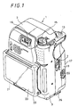
- FIG. 1 is a perspective view showing a single-unit video camera-recorder according to a first embodiment of the present invention from the rear surface thereof;
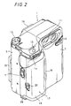
- FIG. 2 is a perspective view showing the single-unit video camera-recorder according to the first embodiment of the present invention from the front surface thereof;
- FIG. 3 is a perspective view of the single-unit video camera-recorder according to the embodiment of the present invention under the condition that a lid portion thereof is opened;
- FIG. 4 is a bottom view of the single-unit video camera-recorder according to the first embodiment of the present invention;
- FIG. 5 is a side view of the single-unit video camera recorder according to the first embodiment of the present invention;
- FIG. 6 is a plan view of a cassette eject mechanism used in the single-unit video camera-recorder according to the present invention;
- FIG. 7 is a diagram showing the operated state of the cassette eject mechanism of the single-unit video camera-recorder according to the first embodiment of the present invention;
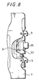
- FIG. 8 is a front view of a lid pop-up mechanism according to the present invention;
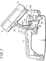
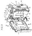
- FIG. 9 is a perspective view of the single-unit video camera-recorder under the condition that a lid portion is opened;
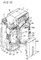
- FIG. 10 is a perspective view showing a battery mechanism portion with a battery lid portion being opened according to a second embodiment of the present invention;
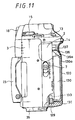
- FIG. 11 is a longitudinal cross-sectional view of a single-unit video camera-recorder according to the second embodiment of the present invention under the condition that a battery thereof is attached;
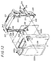
- FIG. 12 is an exploded perspective view of a mechanical chassis supporting mechanism according to a third embodiment of the present invention; and
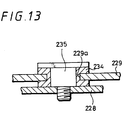
- FIG. 13 is an enlarged cross-sectional view of a damper means used in the third embodiment according to the present invention.
- A cassette eject mechanism of a recording or reproducing apparatus according to a first embodiment of the present invention will be described with reference to the drawings, in which case the cassette eject mechanism according to the present invention is applied to a single-unit video camera-recorder.
- FIG. 1 of the accompanying drawings is a perspective view showing an outer face of a single-unit video camera-recorder according to a first embodiment of the present invention from the rear surface thereof. FIG. 2 is a perspective view showing an outer face of the same single-unit video camera-recorder from the front surface thereof. FIG. 3 is a perspective view showing the same single-unit video camera-recorder with its lid portion opened. FIG. 4 is a bottom view of the same single-unit video camera-recorder. FIG. 5 is a side view of the same single-unit video camera-recorder presented when in use. FIG. 6 is a plan view showing the cassette eject mechanism used in the single-unit video camera-recorder.
- As illustrated, a single-unit video camera-recorder is generally depicted by
reference numeral 1. Initially, main portions of the single-unit video camera-recorder 1 will be described below. As illustrated, a casing or housing of the single-unit video camera-recorder 1 comprises amain body portion 2 and alid portion 3. Thelid portion 3 is openably and closably supported to themain body portion 2 by ahinge portion 4. Thelid portion 3 is closed when levers 5, 5 provided on open end of the other side portion are locked into engagement holes 6, 6 bored through the end portion of themain body portion 2. Thelid portion 3 can be released from the locked state by sliding a lid lock releasingslide bar 7 and can be opened. - The
lid portion 3 that can be rotated about thehinge portion 4 relative to themain body portion 2 includes a pair of upper andlower guide arms 8, 9 of arcuate configuration rotatable about thehinge portion 4 fixed thereto byscrews guide arms 8, 9 includesguide slots main body portion 2 side are engaged, thereby assisting thelid portion 3 to be opened and closed. - As shown in FIG. 2, a
lens window 11 of a camera portion is provided on the upper portion of the front wall of themain body portion 2. Asound collecting portion 12 is provided near thelens window 11. Themain body portion 2 includes a camera mode start/stop button 13 provided on the upper one side thereof. A switchinglever 14 is provided near the start/stop button 14 to switch a wide angle mode and a telephoto mode of the camera portion. A camera mode and video modeswitching operation dial 15 is provided on the upper portion of another one side of themain body portion 2. As shown in FIG. 1, aviewfinder 16 is provided on the upper rear surface portion of themain body portion 2. - The
main body portion 2 includes abattery accommodating portion 17 formed on one side portion of the front wall thereof. Thebattery accommodating portion 17 comprises an accommodating concave portion (not shown) formed on themain body portion 2 and alid portion 19 supported openable and closable to themain body portion 2 by means of ahinge portion 18. Thelid portion 19 can be opened by sliding a lock releasingslide button 20. - The
lid portion 3 includes on its rear wall a liquidcrystal display portion 21 which can display a picture to be monitored as shown in FIG. 1. As shown in FIG. 1, the liquidcrystal display portion 21 is held by aframe 22 and theframe 22 includes an openable andclosable hood 23 of a foldable type. The user can watch the liquidcrystal display portion 21 by spreading thehood 23 as shown in FIG. 5. - The
frame 22 is pivotally supported at its upper end portion to thelid portion 3 by means of ahinge metal fitting 24. An angle of theframe 22 can be changed by anancillary arm 25 as shown in FIG. 5. Therefore, the cameraman can take a picture while watching the liquidcrystal display portion 21 under the condition that the liquidcrystal display portion 21 is set at a desired angle by rotating theframe 22 in adjustment. - The
main body portion 2 includes on its bottom wall provided a supportingplate 26 which can electrically connect the single-unit video camera-recorder 1 to a station (not shown) as shown in FIG. 4. The supportingplate 26 is composed of an openable andclosable shutter 26a and aterminal block 26b disposed on the inside of theshutter 26a. The above-mentioned station is a connection apparatus that enables information recorded by the single-unit video camera-recorder to be recorded and reproduced by a television receiver or to be dubbed by another VTR. - The
main body portion 2 includes acassette compartment 27 of a recording or reproducing apparatus provided therein. Thelid portion 3 can serve as a cassette lid of thecassette compartment 27. Thecassette compartment 27 can eject the tape cassette in a so-called linear skate fashion. - A cassette eject mechanism of the
cassette compartment 27 will be described below with reference to FIGS. 6 and 7. FIG. 7 shows the operated state of the cassette eject mechanism. Of the pair ofguide arms 8, 9 which assist thelid portion 3 to open and close, thelower guide arm 9 includes anoperation member 28 projected on its tip end portion. An eject switch 30 is disposed on thebase plate 29 provided on themain body portion 2 side in response to theoperation member 28. The eject switch 30 is electrically connected to a motor (not shown) for the eject operation of thecassette compartment 27. - The
guide arm 9 includes an inclined steppedlock portion 31 formed on the opposite side of the side in which theoperation member 28 is provided. Thelock portion 31 faces aspring portion 32 supported to thebase plate 29 and constructs the locking mechanism. - When the
lid portion 3 is opened, theoperation member 28 of theguide arm 9 that moves together with the opening of thelid portion 3 pushes the projectedmember 30a of theeject switch 30 and switches theeject switch 30. Therefore, the eject operation motor (not shown) of thecassette compartment 27 is driven and thecassette compartment 27 is operated in a linear skating fashion so that the tape cassette can be loaded onto and/or unloaded from thecassette compartment 27. - At the same time when the eject operation of the
cassette compartment 27 is carried out by operating theeject switch 30 in synchronism with the close operation of thelid portion 3, thelock portion 31 of theguide arm 9 comes in engagement with aspring member 32, whereby thelid portion 3 is locked under the condition that it is opened at maximum. Therefore, thelid portion 3 maintains the maximum opened state and thelid portion 3 can be prevented from being closed recklessly so long as a large closing force is not applied thereto. - The
lid portion 3 can be released from the locked state when thelock member 31 of theguide arm 9 passes thespring member 32 by a force in the closing direction. Simultaneously, theoperation member 28 of theguide arm 9 is released from the projectedmember 30a of theeject switch 30 and theeject switch 30 is disabled so that thecassette compartment 27 is moved at the loading position in a ganged relation to theeject switch 30. Thereafter, thelevers lid portion 3 are locked into the engagement holes 6, 6 bored through themain body portion 2 side, thereby thelid portion 3 being placed in the closed state. - On the other hand, the
lid portion 3 includes a lid pop-up mechanism independently of the cassette eject mechanism. As shown in FIG. 8, this lid pop-up mechanism is composed of aframe 33 supported to the rear surface of thelid portion 3 at the intermediate position of thelevers member 35 held to thelid portion 3 by aspring member 34 in the projected direction. - Specifically, under the condition that the
lid portion 3 is in the closed state, the pop-upmember 35 is urged against the end portion of themain body portion 2 against the spring force of thespring member 34. When thelid portion 3 is released from the locked state by operating the lid lock releasingslide switch 7, thelid portion 3 can be popped up under the spring force of thespring member 34 urged against the pop-upmember 35. - As another action of the lid pop-up mechanism, it is possible to confirm that the
lid portion 3 is not closed completely because thelid portion 3 is popped up by the pop-upmember 35 if thelid portion 3 is not reliably locked when thelid portion 3 is being closed. - The
lid portion 3 can be rotated about thehinge portion 4 in the opening direction by removing thescrews lid portion 3, as shown in FIG. 9. Therefore, it is possible to repair and inspect thedrum head 27a, such as cleaning of thedrum head 27a or exchange theworn drum head 27a or to repair and inspect the tape path mechanism portion, such as cleaning of thetape guide system 27a of the tape path mechanism portion and a tape path adjustment with ease without disassembling themain body portion 2 and thelid portion 3. - Since the eject operation of the
cassette compartment 27 is carried out by operating theeject switch 30 in a ganged relation with the opening operation of thelid portion 3 as described above, it becomes unnecessary to dispose a cassette eject button on the surface of the housing unlike the prior art. As a consequence, it is possible to reliably prevent the tape cassette from being ejected inadvertently during the single-unit video camera-recorder is being operated. - Since the
lid portion 3 is locked under the condition that it is opened at maximum, thelid portion 3 can be prevented from being closed so long as thelid portion 3 is not closed by a recklessly large force. Therefore, the tape cassette can reliably be loaded to and/or unloaded from the cassette compartment which is placed under the eject state. - Since the recording or reproducing apparatus includes the lid pop-up mechanism, the
lid portion 2 is set in the popped-up state so long as thelid portion 3 is not closed completely. Therefore, it is possible to prevent the recording or reproducing apparatus from being used under the condition that thelid portion 3 remains opened. - Further, since the
lid portion 3 is rotated about thehinge portion 4 in the opening direction by a large amount, it is possible to easily perform the repair and inspection, such as cleaning of the head drum and exchanging of the worn head drum or to perform repair and inspection, such as the tape path adjustment or the like without disassembling themain body portion 2 and thelid portion 3. As a consequence, it becomes possible to reduce the repair processes of the mechanical deck considerably. - While the lid pop-up mechanism is shown disposed on the
lid portion 3 side as described above, the lid pop-up mechanism could be disposed on themain body portion 2 side. - While the cassette eject mechanism is shown applied to a single-unit video camera-recorder as described above, it could be applied to a variety of recording and reproducing apparatus.
- As described above, in the cassette eject mechanism of recording or reproducing apparatus comprising a main body portion in which a cassette compartment is incorporated and a lid portion supported to the main body portion so as to become openable and closable about a hinge portion, since the lid portion includes a pair of guide arms which assist the lid portion to be opened and closed relative to the main body portion in which a cassette eject switch is opened in a ganged relation with the opening operation of the lid portion, the cassette eject button need not be disposed on the surface of the housing of the recording or reproducing apparatus. As a consequence, it becomes possible to reliably prevent the tape cassette from being ejected during the single-unit video camera recorder is being operated.
- Furthermore, since the cassette eject button is reduced, it is possible to make the recording or reproducing apparatus easy to handle.
- A battery loading mechanism will be described below with reference to FIGS. 10 and 11. In FIGS. 10 and 11, like parts corresponding to those of the first embodiment are marked with the same references and therefore need not be described in detail.
- The battery accommodating
concave portion 118 is formed by forming themain body portion 2 in a concave by molding. A pair ofelectrode terminals concave portion 118. Theelectrode terminals shutter member 131 which can be elevated and lowered under the spring force of a spring member (not shown) when thebattery 130 is not accommodated into the battery accommodatingconcave portion 118. The battery accommodatingconcave portion 118 includes on its bottom surface marked anindication mark 132 to indicate the direction in which thebattery 130 is accommodated into the battery accommodatingconcave portion 118. - In this embodiment, the
battery 130 may be a battery pack-type battery formed of a lithium battery and therefore thebattery 130 includes a pair ofelectrodes 133 provided on side end portions thereof. - The
lid cover 120 that is supported to themain body portion 2 by means of thehinge portion 119 includes at its open end portions provided a pair of lock levers 134 (only onelock lever 134 is illustrated in FIG. 10) to become slidable by the operation of the lock releasingslide switch 21. When the lock levers 134, 134 are engaged into lockingapertures concave portion 118, the lock levers 134, 134 are locked thereto under the condition that thelid cover 120 is in the opened state. - The
lid cover 120 includes on its upper rear surface portion provided a pair ofparallel ribs battery 130 to a proper position at which thebattery 130 is loaded into the battery accommodatingconcave portion 118. The tworibs frame 137 provided on thelid cover 120 by molding. A front surface portion of each of theribs inclined surface 136a of substantially 45°. Furthermore, theribs hinge portion 119 of thelid cover 120. - Operation of the battery loading mechanism according to the second embodiment will be described with reference to FIG. 11 also.
- Initially, the
battery 130 is accommodated into the battery accommodatingconcave portion 118 in accordance with theindication mark 132, and then thelid cover 120 is closed. When thelid cover 120 is being closed, theinclined surfaces ribs lid cover 120 are brought in contact with anupper corner portion 130a of thebattery 130. When thelid cover 120 is further rotated in the closing direction under this condition, thebattery 130 is lowered toward theelectrode terminals inclined surfaces battery 130 is translated in the lower direction, whereby theshutter 131 is lowered against a spring force of a spring member (not shown). Consequently, at the same time when thelid cover 120 is closed and locked, theelectrode terminals electrodes battery 130 to make thebattery 130 and the single-unit video camera-recorder become electrically conductive. Then, the loading state of thebattery 130 is completed. - As described above, since the
battery 130 can be locked at the loading position while thebattery 130 can be maintained electrically conductive only by closing and locking thelid cover 120 under the condition that thebattery 130 is accommodated within the battery accommodatingconcave portion 118, thebattery 130 can be loaded reliably with ease. Therefore, the single-unit video camera-recorder becomes easy to handle considerably. - Since the battery loading mechanism itself can extremely be simplified in structure, the number of assembly parts can considerably be reduced with the result that the assembling cost of the single-unit video camera-recorder can be reduced and that the single-unit video camera-recorder can be made inexpensive.
- Since the
ribs hinge portion 119 which becomes a supporting point at which thelid cover 120 is opened and closed, there is then the advantage that a pushing force for pushing thebattery 130 by theribs lid cover 120 is being closed. - Further, since the
upper corner portion 130a of thebattery 130 is constantly urged against theinclined surfaces ribs lid cover 120 when thelid cover 120 is closed and locked under the condition that thebattery 130 is loaded into the battery accommodatingconcave portion 118, thebattery 130 can be prevented from being loosely fitted into the battery accommodatingconcave portion 118. Thus, thebattery 130 can be loaded into the battery accommodatingconcave portion 118 stably. - While the two
parallel ribs ribs battery 130. - Furthermore, while the battery loading mechanism according to this embodiment is applied to the single-unit video camera-recorder as described above, it could be applied to a wide variety of battery loading mechanisms of electronic equipments, such as a recording and reproducing apparatus, a liquid crystal television receiver or the like.
- As set out above, the battery loading mechanism of the electronic equipment includes the battery accommodating concave portion provided within the housing of the electronic equipment and the lid portion provided in the housing so as to become openable and closable to the battery accommodating concave portion about the hinge portion wherein the battery is positioned at the loading position of the battery accommodating concave portion in a ganged relation with the closing operation of the lid portion, the battery loading operation becomes reliable and easy. Thus, the battery loading mechanism becomes easy to handle considerably.
- Moreover, the battery loading mechanism itself become extremely simple in structure and the number of assembly parts can considerably be reduced. Therefore, the assembling cost can be reduced and the apparatus can be made inexpensive.
- A mechanical chassis supporting mechanism according to a third embodiment will be described with reference to FIGS. 12 and 13. In FIGS. 12 and 13, elements and parts identical to those of the first and second embodiments are marked with the same references and therefore need not be described in detail.
- As shown in FIG. 12, the
mechanical chassis 228 includesframes cassette compartment 227 is mounted. Theframe 229 on the drum side is secured to themechanical chassis 228 by means of asingle screw 231 and theframe 230 on the opposite side of the drum side is secured to themechanical chassis 228 by means of twoscrews - The
frame 229 on the drum side is supported to themechanical chassis 228 through a damper means 233 serving as a stress absorption member provided independently of thescrew 231. The damper means 233 will be described below with reference to FIG. 13. As shown in FIG. 13, the damper means 233 is formed of asilicon damper rubber 234. Thesilicon damper rubber 234 is fitted into and supported in ahole 229a bored through theframe 229. Thedamper rubber 234 is fixed at its center to themechanical chassis 228 by way of a steppedscrew 235. Thus, theframe 229 is supported to themechanical chassis 228 via thedamper rubber 234. - Referring back to FIG. 12, the
frame 229 on the drum side includes a supportingmember 236 having aresilient structure 236a distant from the fixed position of thescrew 231 in the front and back direction but it is substantially coaxial therewith. Theframe 230 on the opposite side of the drum side includes supportingportions frame 230 is fixed to themechanical chassis 228 by the twoscrews - Although the
mechanical chassis 228 is secured to themain body portion 2 via theframes dot chain line 238 in FIG. 12 is secured to the rear surface of themechanical chassis 228. Aboss 222a formed on themain body portion 2 is secured to the supportingportion 236 of theframe 229 of the drum side by ascrew 239. Bosses 222b, 222b formed on themain body portion 2 are respectively secured to the supportingportions frame 230 of the opposite side of the drum side by means ofscrews - According to the thus arranged mechanical chassis supporting mechanism, since the
frame 229 of the drum side is supported to themechanical chassis 228 by thescrew 231 in a one-point supporting fashion and themain body portion 2 is supported to the supportingportion 236 of theframe 229 by thescrew 239 in a one-point supporting fashion, even when an external stress, such as a twisting force or the like is applied to theframe 229 from themain body portion 2 or thelid portion 3, not shown, theframe 229 is swingably moved about the supportingpoint 236 at which themain body portion 2 or thelid portion 3 is supported in a one-point supporting fashion. Therefore, the external stress based on the twisting force can be prevented from being applied to themechanical chassis 228 portion of the drum side. As a result, a very small displacement can be prevented from being produced between the tape path mechanisms formed on themechanical chassis 228 so that the tape path can be produced accurately relative to the drum. - Since the
frame 229 on the drum side is fixed to themechanical chassis 228 by means of the damper means 233 provided independently of thescrew 231, theframe 229 is stably supported to themechanical chassis 228 and the external stress, such as the twisting force or the like applied to theframe 229 can be absorbed by the damper means 233. Thus, the external stress can be prevented from being transmitted to themechanical chassis 228. - Further, since the
frame 229 includes thescrew 231 secured to themechanical chassis 28 and the supportingportion 236 for supporting themain body portion 2 and thescrew 231 and the supportingportion 236 are disposed substantially coaxially, even when theframe 229 is applied with the external stress, such as the twisting force or the like from themain body portion 2, theframe 229 can swingably be moved effectively. - Furthermore, since the supporting
portion 236 that supports themain body portion 2 in a one-point supporting fashion is formed as theresilient structure 236a, the external stress applied to theframe 229 from themain body portion 2 can be absorbed by theresilient structure 236a to some extent and the swing operation of theframe 229 can be suppressed to the minimum. - While the described mechanical chassis supporting mechanism according to the third embodiment is applied to the single-unit video camera-recorder by way of example, the mechanical chassis supporting mechanism could be applied to a wide variety of recording and/or reproducing apparatus and reproducing apparatus.
- As set out above, since the mechanical chassis supporting mechanism for a recording apparatus comprises the mechanical chassis on which the cassette compartment is mounted, the supporting members respectively supported to the drum side and the opposite side of the drum side of the mechanical chassis and the outer housing for supporting the mechanical chassis by means of the two supporting members, the supporting member on the drum side is supported to the mechanical chassis by one screw member in a one-point supporting fashion and the supporting member on the opposite side of the drum side is supported to the mechanical chassis by the two screws in a two-point supporting fashion. Therefore, the external stress, such as the twisting force or the like can be prevented from being transmitted to the mechanical chassis on the drum side and the very small displacement can be prevented from being produced between the tape path mechanisms and the accurate tape path can be produced on the drum. Therefore, the mechanical chassis supporting mechanism is suitable for the recording apparatus whose mechanical chassis or outer housing can be reduced in thickness in order to be miniaturized and made light in weight.
Claims (20)
- A cassette eject mechanism for a recording or reproducing apparatus, comprising:
a main body portion (2) having a cassette compartment (27) disposed therein;
a lid portion (3) supported on the main body portion by means of a hinge portion (4) so as to become openable and closable about the hinge portion (4); and
a pair of guide arms (8, 9) supported on the lid portion (3) to assist the lid portion (3) to be opened and closed relative to the main body portion (2), wherein a cassette eject switch (30) is operated in a ganged relation to an opening operation of the lid portion (3). - A cassette eject mechanism for a recording or reproducing apparatus according to claim 1, wherein the cassette eject switch is energized by one of the pair of guide arms.
- A cassette eject mechanism for a recording or reproducing apparatus according to claim 1, wherein the guide arm includes a lock mechanism to lock the lid portion when the lid portion is in the opened state.
- A cassette eject mechanism for a recording or reproducing apparatus according to claim 1, wherein either of the lid portion and the main body portion includes a lid pop-up mechanism.
- A cassette eject mechanism for a recording or reproducing apparatus according to claim 1, wherein when the pair of guide arms are detached from the lid portion, the lid portion is opened wide to expose a drum portion of the recording or reproducing apparatus.
- A cassette eject mechanism for a recording or reproducing apparatus according to claim 2, wherein the guide arm includes a lock mechanism to lock the lid portion when the lid portion is in the opened state.
- A cassette eject mechanism for a recording or reproducing apparatus according to claim 6, wherein either of the lid portion and the main body portion includes a lid pop-up mechanism.
- A cassette eject mechanism for a recording or reproducing apparatus according to claim 7, wherein when the pair of guide arms are detached from the lid portion, the lid portion is opened wide to expose a drum portion of the recording or reproducing apparatus.
- A battery loading mechanism for an electronic equipment comprising:
a battery accommodating concave portion (118) provided on a housing (2) of the electronic equipment;
a lid portion (120) provided on the housing (2) so as to become openable and closable about a hinge portion (119) relative to the battery accommodating concave portion (118); and
positioning means (136, 136) for positioning a battery (130) to a loading position of the battery accommodating concave portion (118) in a ganged relation to a closing operation of the lid portion (120). - A battery loading mechanism for an electronic equipment according to claim 9, wherein the lid portion includes at its part a pushing member for urging the battery against the loading position of the battery accommodating concave portion.
- A battery loading mechanism for an electronic equipment according to claim 10, wherein the pushing member is formed by a rib having an inclined surface.
- A battery loading mechanism for an electronic equipment according to claim 10, wherein the pushing member is disposed at the position distant from a supporting point at which the lid portion of the battery is rotated.
- A mechanical chassis supporting mechanism in a recording or reproducing apparatus comprising:
a mechanical chassis (228) having a cassette compartment (227) mounted thereon;
supporting members (229, 230) respectively supported on the mechanical chassis (228) on its drum side and on its opposite side of the drum side in the rear surface of the mechanical chassis (228);
an outer housing for supporting the mechanical chassis through the two supporting members (229, 230); and
supporting means in which the supporting member (229) on the drum side is supported to the mechanical chassis (228) by a single screw (231) in a one-point supporting fashion and the supporting member (230) on the opposite side of the drum side is supported to the mechanical chassis (228) by two screws (232, 232) in a two-point fashion. - A mechanical chassis supporting mechanism in a recording or reproducing apparatus according to claim 13, wherein the supporting member on the drum side is supported to the mechanical chassis through a stress absorption member independently of the screw member.
- A mechanical chassis supporting mechanism in a recording or reproducing apparatus according to claim 13, wherein the supporting member on the drum side is supported to the outer housing by a one screw member in a one-point supporting fashion and the supporting member on the opposite side of the drum side is supported to the outer housing by two screw members in a two-point supporting fashion.
- A mechanical chassis supporting mechanism in a recording or reproducing apparatus according to claim 13, wherein the screw member of the supporting member supported to the mechanical chassis on the drum side and the screw member of the supporting member supported to the drum side of the outer housing are disposed close to each other in a coaxial state.
- A mechanical chassis supporting mechanism in a recording or reproducing apparatus according to claim 13, wherein a supporting portion of the supporting member of the drum side supported to the outer housing has a resilient structure.
- A mechanical chassis supporting mechanism in a recording or reproducing apparatus according to claim 15, wherein the supporting member on the drum side is supported to the outer housing by a single screw member in a one-point supporting fashion and the supporting member on the opposite side of the drum side is supported to the outer housing by two screw members in a two-point supporting fashion.
- A mechanical chassis supporting mechanism in a recording or reproducing apparatus according to claim 18, wherein the screw member of the supporting member supported to the mechanical chassis on the drum side and the screw member of the supporting member supported to the drum side of the outer housing are disposed close to each other in a coaxial state.
- A mechanical chassis supporting mechanism in a recording or reproducing apparatus according to claim 19, wherein a supporting portion of the supporting member of the drum side supported to the outer housing has a resilient structure.
Priority Applications (2)
| Application Number | Priority Date | Filing Date | Title |
|---|---|---|---|
| EP98203900A EP0903745B1 (en) | 1993-08-24 | 1994-08-18 | Battery loading mechanism |
| EP98203902A EP0910085B1 (en) | 1993-08-24 | 1994-08-18 | Mechanical chassis supporting mechanism |
Applications Claiming Priority (9)
| Application Number | Priority Date | Filing Date | Title |
|---|---|---|---|
| JP20962493A JP3240767B2 (en) | 1993-08-24 | 1993-08-24 | Cassette attaching / detaching mechanism of recording and / or reproducing apparatus and recording and / or reproducing apparatus |
| JP20962693A JP3318630B2 (en) | 1993-08-24 | 1993-08-24 | Holding mechanism of mechanical chassis in video recorder |
| JP209625/93 | 1993-08-24 | ||
| JP20962493 | 1993-08-24 | ||
| JP20962593 | 1993-08-24 | ||
| JP5209625A JPH0767007A (en) | 1993-08-24 | 1993-08-24 | Battery loading mechanism for electronic equipment device |
| JP209626/93 | 1993-08-24 | ||
| JP209624/93 | 1993-08-24 | ||
| JP20962693 | 1993-08-24 |
Related Child Applications (2)
| Application Number | Title | Priority Date | Filing Date |
|---|---|---|---|
| EP98203902A Division EP0910085B1 (en) | 1993-08-24 | 1994-08-18 | Mechanical chassis supporting mechanism |
| EP98203900A Division EP0903745B1 (en) | 1993-08-24 | 1994-08-18 | Battery loading mechanism |
Publications (3)
| Publication Number | Publication Date |
|---|---|
| EP0640973A2 true EP0640973A2 (en) | 1995-03-01 |
| EP0640973A3 EP0640973A3 (en) | 1996-12-11 |
| EP0640973B1 EP0640973B1 (en) | 2001-10-31 |
Family
ID=27329027
Family Applications (3)
| Application Number | Title | Priority Date | Filing Date |
|---|---|---|---|
| EP98203902A Expired - Lifetime EP0910085B1 (en) | 1993-08-24 | 1994-08-18 | Mechanical chassis supporting mechanism |
| EP94306101A Expired - Lifetime EP0640973B1 (en) | 1993-08-24 | 1994-08-18 | Cassette eject mechanism, battery loading mechanism and mechanical chassis supporting mechanism |
| EP98203900A Expired - Lifetime EP0903745B1 (en) | 1993-08-24 | 1994-08-18 | Battery loading mechanism |
Family Applications Before (1)
| Application Number | Title | Priority Date | Filing Date |
|---|---|---|---|
| EP98203902A Expired - Lifetime EP0910085B1 (en) | 1993-08-24 | 1994-08-18 | Mechanical chassis supporting mechanism |
Family Applications After (1)
| Application Number | Title | Priority Date | Filing Date |
|---|---|---|---|
| EP98203900A Expired - Lifetime EP0903745B1 (en) | 1993-08-24 | 1994-08-18 | Battery loading mechanism |
Country Status (6)
| Country | Link |
|---|---|
| US (3) | US5539463A (en) |
| EP (3) | EP0910085B1 (en) |
| KR (1) | KR100327459B1 (en) |
| CA (1) | CA2130011C (en) |
| DE (3) | DE69432371T2 (en) |
| TW (3) | TW293120B (en) |
Cited By (1)
| Publication number | Priority date | Publication date | Assignee | Title |
|---|---|---|---|---|
| EP0825768A2 (en) * | 1996-08-22 | 1998-02-25 | Matsushita Electric Industrial Co., Ltd. | Video camera with electronic monitor |
Families Citing this family (21)
| Publication number | Priority date | Publication date | Assignee | Title |
|---|---|---|---|---|
| DE69513224T2 (en) * | 1994-05-12 | 2000-07-13 | Matsushita Electric Ind Co Ltd | Video camera |
| JP3496207B2 (en) * | 1994-06-22 | 2004-02-09 | ソニー株式会社 | Video camera |
| JPH08125890A (en) * | 1994-10-21 | 1996-05-17 | Sony Corp | Video camera |
| JP3612801B2 (en) * | 1995-07-03 | 2005-01-19 | ソニー株式会社 | Electronics |
| US7092030B1 (en) * | 1997-09-03 | 2006-08-15 | Canon Kabushiki Kaisha | Image pickup apparatus with prism optical system |
| JPH11271592A (en) * | 1998-03-24 | 1999-10-08 | Fuji Photo Optical Co Ltd | Operating device for television lens |
| US6462780B1 (en) * | 1998-07-10 | 2002-10-08 | Eastman Kodak Company | Power and signal interconnection scheme for a personal electronic product |
| FI20002897A (en) * | 2000-12-29 | 2002-06-30 | Nokia Corp | Electronic device and means to insure a detachable unit in a functional position |
| TW460006U (en) * | 2000-12-30 | 2001-10-11 | Inventec Multimedia & Telecom | Portable expanding-type apparatus for digital camera |
| TW495130U (en) | 2001-02-09 | 2002-07-11 | Acer Inc | Flat display device and the rotatory structure thereof |
| KR20050088002A (en) * | 2004-02-28 | 2005-09-01 | 삼성전자주식회사 | Inage photograping apparatus and a method assembling the same |
| KR20050090821A (en) * | 2004-03-10 | 2005-09-14 | 삼성전자주식회사 | Housing cover for image photographing appratus |
| KR20050090820A (en) * | 2004-03-10 | 2005-09-14 | 삼성전자주식회사 | Image photographing appratus |
| KR20050090783A (en) * | 2004-03-10 | 2005-09-14 | 삼성전자주식회사 | Deck chassis structure for magnetic recording/reading apparatus |
| US20060092319A1 (en) * | 2004-10-18 | 2006-05-04 | Matsushita Electric Industrial Co., Ltd. | Image pickup apparatus |
| JP2007157238A (en) * | 2005-12-05 | 2007-06-21 | Sony Corp | Electronic equipment and imaging device |
| US7896564B2 (en) * | 2006-11-16 | 2011-03-01 | Datamax-O'neil Corporation | Portable printer |
| CN101662007B (en) * | 2008-08-29 | 2013-03-13 | 深圳富泰宏精密工业有限公司 | Structure of battery cover |
| JP1573871S (en) * | 2016-07-06 | 2017-04-10 | ||
| JP1573659S (en) * | 2016-07-06 | 2017-04-10 | ||
| JP6612925B2 (en) * | 2017-09-29 | 2019-11-27 | 本田技研工業株式会社 | Magazine type charger |
Citations (14)
| Publication number | Priority date | Publication date | Assignee | Title |
|---|---|---|---|---|
| GB2011156A (en) * | 1977-12-22 | 1979-07-04 | Philips Nv | Battery holder |
| US4468439A (en) * | 1981-10-15 | 1984-08-28 | Canon Kabushiki Kaisha | Battery loading device |
| JPS62105579A (en) * | 1985-11-01 | 1987-05-16 | Sony Corp | Video camera |
| US4853302A (en) * | 1985-10-21 | 1989-08-01 | Minolta Camera Kabushiki Kaisha | Battery compartment |
| EP0393647A2 (en) * | 1989-04-19 | 1990-10-24 | Sony Corporation | Portable recording and/or reproducing apparatus |
| EP0401475A2 (en) * | 1989-06-07 | 1990-12-12 | Pioneer Electronic Corporation | Recording medium player apparatus |
| GB2241371A (en) * | 1989-11-30 | 1991-08-28 | Samsung Electronics Co Ltd | Video cameras |
| US5121268A (en) * | 1989-07-25 | 1992-06-09 | Teac Corporation | Apparatus for recording and/or reproducing information with a lid for protecting the recording medium and a recording medium loading/ejecting mechanism |
| JPH04365270A (en) * | 1991-06-13 | 1992-12-17 | Canon Inc | Video camera |
| EP0519456A1 (en) * | 1991-06-18 | 1992-12-23 | Canon Kabushiki Kaisha | Video camera |
| EP0522330A2 (en) * | 1991-06-18 | 1993-01-13 | Canon Kabushiki Kaisha | Camera-integrated video recorder apparatus |
| EP0528420A2 (en) * | 1991-08-20 | 1993-02-24 | Sony Corporation | Disk loading system |
| WO1993006589A1 (en) * | 1991-09-13 | 1993-04-01 | Seiko Epson Corporation | Portable sound reproducing and amplifying apparatus |
| EP0541449A2 (en) * | 1991-11-08 | 1993-05-12 | Sony Corporation | Miniaturized video camera |
Family Cites Families (13)
| Publication number | Priority date | Publication date | Assignee | Title |
|---|---|---|---|---|
| US4371594A (en) * | 1980-10-03 | 1983-02-01 | Canon Kabushiki Kaisha | Battery accommodating device |
| US4391883A (en) * | 1981-09-28 | 1983-07-05 | Motorola, Inc. | Housing arrangement with breakaway battery access door |
| US4829984A (en) * | 1983-12-15 | 1989-05-16 | Gordon Robert T | Method for the improvement of transplantation techniques and for the preservation of tissue |
| JPS6272280A (en) * | 1985-09-25 | 1987-04-02 | Canon Inc | Electronic camera |
| JPS63193773A (en) * | 1987-02-06 | 1988-08-11 | Hitachi Ltd | Vtr unified camera equipped with reproducing function |
| US4847170A (en) * | 1988-09-09 | 1989-07-11 | Pulse Electronics, Inc. | Battery container and adapter |
| JPH0295085A (en) * | 1988-09-30 | 1990-04-05 | Sony Corp | Video camera |
| JPH0516779Y2 (en) * | 1988-10-04 | 1993-05-06 | ||
| JPH02289961A (en) * | 1989-04-28 | 1990-11-29 | Sony Corp | Portable recording and reproducing device |
| JP3035784B2 (en) * | 1990-01-09 | 2000-04-24 | コニカ株式会社 | Image recording device |
| JP2832097B2 (en) * | 1991-06-18 | 1998-12-02 | キヤノン株式会社 | Camera-integrated video recorder |
| JP2994846B2 (en) * | 1992-03-10 | 1999-12-27 | キヤノン株式会社 | camera |
| JPH06225193A (en) * | 1993-01-21 | 1994-08-12 | Konica Corp | Digital electronic still camera |
-
1994
- 1994-08-12 CA CA002130011A patent/CA2130011C/en not_active Expired - Fee Related
- 1994-08-13 TW TW083107423A patent/TW293120B/zh active
- 1994-08-13 TW TW084112050A patent/TW290684B/zh active
- 1994-08-13 TW TW085210558U patent/TW296101U/en unknown
- 1994-08-18 DE DE69432371T patent/DE69432371T2/en not_active Expired - Fee Related
- 1994-08-18 DE DE69431682T patent/DE69431682T2/en not_active Expired - Fee Related
- 1994-08-18 EP EP98203902A patent/EP0910085B1/en not_active Expired - Lifetime
- 1994-08-18 DE DE69428851T patent/DE69428851T2/en not_active Expired - Fee Related
- 1994-08-18 EP EP94306101A patent/EP0640973B1/en not_active Expired - Lifetime
- 1994-08-18 EP EP98203900A patent/EP0903745B1/en not_active Expired - Lifetime
- 1994-08-22 US US08/293,919 patent/US5539463A/en not_active Expired - Lifetime
- 1994-08-23 KR KR1019940020744A patent/KR100327459B1/en not_active IP Right Cessation
-
1995
- 1995-02-23 US US08/393,455 patent/US5822001A/en not_active Expired - Fee Related
- 1995-02-23 US US08/393,454 patent/US5530476A/en not_active Expired - Lifetime
Patent Citations (14)
| Publication number | Priority date | Publication date | Assignee | Title |
|---|---|---|---|---|
| GB2011156A (en) * | 1977-12-22 | 1979-07-04 | Philips Nv | Battery holder |
| US4468439A (en) * | 1981-10-15 | 1984-08-28 | Canon Kabushiki Kaisha | Battery loading device |
| US4853302A (en) * | 1985-10-21 | 1989-08-01 | Minolta Camera Kabushiki Kaisha | Battery compartment |
| JPS62105579A (en) * | 1985-11-01 | 1987-05-16 | Sony Corp | Video camera |
| EP0393647A2 (en) * | 1989-04-19 | 1990-10-24 | Sony Corporation | Portable recording and/or reproducing apparatus |
| EP0401475A2 (en) * | 1989-06-07 | 1990-12-12 | Pioneer Electronic Corporation | Recording medium player apparatus |
| US5121268A (en) * | 1989-07-25 | 1992-06-09 | Teac Corporation | Apparatus for recording and/or reproducing information with a lid for protecting the recording medium and a recording medium loading/ejecting mechanism |
| GB2241371A (en) * | 1989-11-30 | 1991-08-28 | Samsung Electronics Co Ltd | Video cameras |
| JPH04365270A (en) * | 1991-06-13 | 1992-12-17 | Canon Inc | Video camera |
| EP0519456A1 (en) * | 1991-06-18 | 1992-12-23 | Canon Kabushiki Kaisha | Video camera |
| EP0522330A2 (en) * | 1991-06-18 | 1993-01-13 | Canon Kabushiki Kaisha | Camera-integrated video recorder apparatus |
| EP0528420A2 (en) * | 1991-08-20 | 1993-02-24 | Sony Corporation | Disk loading system |
| WO1993006589A1 (en) * | 1991-09-13 | 1993-04-01 | Seiko Epson Corporation | Portable sound reproducing and amplifying apparatus |
| EP0541449A2 (en) * | 1991-11-08 | 1993-05-12 | Sony Corporation | Miniaturized video camera |
Non-Patent Citations (2)
| Title |
|---|
| PATENT ABSTRACTS OF JAPAN vol. 11, no. 312 (E-548), 12 October 1987 & JP-A-62 105579 (SONY CORP.), 16 May 1987, * |
| PATENT ABSTRACTS OF JAPAN vol. 17, no. 238 (E-1363), 13 May 1993 & JP-A-04 365270 (CANON INC.), 17 December 1992, * |
Cited By (3)
| Publication number | Priority date | Publication date | Assignee | Title |
|---|---|---|---|---|
| EP0825768A2 (en) * | 1996-08-22 | 1998-02-25 | Matsushita Electric Industrial Co., Ltd. | Video camera with electronic monitor |
| EP0825768A3 (en) * | 1996-08-22 | 1999-12-29 | Matsushita Electric Industrial Co., Ltd. | Video camera with electronic monitor |
| US6115069A (en) * | 1996-08-22 | 2000-09-05 | Matsushita Electric Industrial Co., Ltd. | Video camera with swingable electronic monitor mounted on the same side of the camera as the cassette holder |
Also Published As
| Publication number | Publication date |
|---|---|
| EP0910085B1 (en) | 2002-11-06 |
| US5530476A (en) | 1996-06-25 |
| EP0903745B1 (en) | 2003-03-26 |
| TW290684B (en) | 1996-11-11 |
| KR950006844A (en) | 1995-03-21 |
| TW296101U (en) | 1997-01-11 |
| DE69432371D1 (en) | 2003-04-30 |
| DE69432371T2 (en) | 2004-03-04 |
| TW293120B (en) | 1996-12-11 |
| DE69428851T2 (en) | 2002-06-27 |
| DE69431682D1 (en) | 2002-12-12 |
| DE69431682T2 (en) | 2003-09-18 |
| US5539463A (en) | 1996-07-23 |
| EP0903745A3 (en) | 1999-05-12 |
| EP0910085A3 (en) | 1999-05-12 |
| KR100327459B1 (en) | 2002-11-20 |
| US5822001A (en) | 1998-10-13 |
| EP0903745A2 (en) | 1999-03-24 |
| CA2130011C (en) | 2004-03-30 |
| EP0910085A2 (en) | 1999-04-21 |
| EP0640973B1 (en) | 2001-10-31 |
| DE69428851D1 (en) | 2001-12-06 |
| EP0640973A3 (en) | 1996-12-11 |
| CA2130011A1 (en) | 1995-02-25 |
Similar Documents
| Publication | Publication Date | Title |
|---|---|---|
| EP0910085B1 (en) | Mechanical chassis supporting mechanism | |
| US6307743B1 (en) | Electronic apparatus and apparatus for recording and/or playback on recording medium | |
| US5541809A (en) | Electronic equipments chassis made from bent sheet metal | |
| JP2007174584A (en) | Electronic apparatus | |
| JPH0922585A (en) | Electronic equipment | |
| JPH1188818A (en) | Electronic image pickup device | |
| US7275253B2 (en) | Electronic apparatus and apparatus for recording and/or playback on recording medium | |
| JP4228478B2 (en) | Imaging device | |
| JP4300640B2 (en) | Imaging device | |
| JPH0918159A (en) | Electronic apparatus | |
| JPH0698216A (en) | Open/close mechanism for camera lens cover | |
| JP2832098B2 (en) | Camera-integrated video recorder | |
| JP3644040B2 (en) | Portable electronic devices | |
| JP2003101843A (en) | Image recorder | |
| JP4158215B2 (en) | Recording medium recording and / or reproducing apparatus | |
| JPH09163204A (en) | Opening/closing device for battery cover | |
| KR100208005B1 (en) | Lense door on-off apparatus for camcorder | |
| JPH0767007A (en) | Battery loading mechanism for electronic equipment device | |
| JP3918261B2 (en) | Electronics | |
| JP3205973B2 (en) | Camera adapter | |
| JP2004079543A (en) | Electronic apparatus | |
| JP2001053993A (en) | Video camera | |
| JP2000270246A (en) | Video image pickup device | |
| JPH0323554A (en) | Electronic camera | |
| JP2001024918A (en) | Recorder with integrated camera with monitor |
Legal Events
| Date | Code | Title | Description |
|---|---|---|---|
| PUAI | Public reference made under article 153(3) epc to a published international application that has entered the european phase |
Free format text: ORIGINAL CODE: 0009012 |
|
| AK | Designated contracting states |
Kind code of ref document: A2 Designated state(s): DE FR GB IT |
|
| PUAL | Search report despatched |
Free format text: ORIGINAL CODE: 0009013 |
|
| AK | Designated contracting states |
Kind code of ref document: A3 Designated state(s): DE FR GB IT |
|
| 17P | Request for examination filed |
Effective date: 19970422 |
|
| 17Q | First examination report despatched |
Effective date: 19980904 |
|
| GRAG | Despatch of communication of intention to grant |
Free format text: ORIGINAL CODE: EPIDOS AGRA |
|
| GRAG | Despatch of communication of intention to grant |
Free format text: ORIGINAL CODE: EPIDOS AGRA |
|
| GRAH | Despatch of communication of intention to grant a patent |
Free format text: ORIGINAL CODE: EPIDOS IGRA |
|
| GRAH | Despatch of communication of intention to grant a patent |
Free format text: ORIGINAL CODE: EPIDOS IGRA |
|
| GRAA | (expected) grant |
Free format text: ORIGINAL CODE: 0009210 |
|
| AK | Designated contracting states |
Kind code of ref document: B1 Designated state(s): DE FR GB IT |
|
| REF | Corresponds to: |
Ref document number: 69428851 Country of ref document: DE Date of ref document: 20011206 |
|
| REG | Reference to a national code |
Ref country code: GB Ref legal event code: IF02 |
|
| ET | Fr: translation filed | ||
| PLBE | No opposition filed within time limit |
Free format text: ORIGINAL CODE: 0009261 |
|
| STAA | Information on the status of an ep patent application or granted ep patent |
Free format text: STATUS: NO OPPOSITION FILED WITHIN TIME LIMIT |
|
| 26N | No opposition filed | ||
| PGFP | Annual fee paid to national office [announced via postgrant information from national office to epo] |
Ref country code: DE Payment date: 20080829 Year of fee payment: 15 |
|
| PGFP | Annual fee paid to national office [announced via postgrant information from national office to epo] |
Ref country code: IT Payment date: 20080827 Year of fee payment: 15 Ref country code: FR Payment date: 20080818 Year of fee payment: 15 |
|
| PGFP | Annual fee paid to national office [announced via postgrant information from national office to epo] |
Ref country code: GB Payment date: 20080827 Year of fee payment: 15 |
|
| GBPC | Gb: european patent ceased through non-payment of renewal fee |
Effective date: 20090818 |
|
| REG | Reference to a national code |
Ref country code: FR Ref legal event code: ST Effective date: 20100430 |
|
| PG25 | Lapsed in a contracting state [announced via postgrant information from national office to epo] |
Ref country code: FR Free format text: LAPSE BECAUSE OF NON-PAYMENT OF DUE FEES Effective date: 20090831 Ref country code: DE Free format text: LAPSE BECAUSE OF NON-PAYMENT OF DUE FEES Effective date: 20100302 |
|
| PG25 | Lapsed in a contracting state [announced via postgrant information from national office to epo] |
Ref country code: GB Free format text: LAPSE BECAUSE OF NON-PAYMENT OF DUE FEES Effective date: 20090818 |
|
| PG25 | Lapsed in a contracting state [announced via postgrant information from national office to epo] |
Ref country code: IT Free format text: LAPSE BECAUSE OF NON-PAYMENT OF DUE FEES Effective date: 20090818 |