EP0643392A1 - Recording and/or reproducing apparatus for recording medium and damper mechanism employed in such appartus - Google Patents
Recording and/or reproducing apparatus for recording medium and damper mechanism employed in such appartus Download PDFInfo
- Publication number
- EP0643392A1 EP0643392A1 EP94113397A EP94113397A EP0643392A1 EP 0643392 A1 EP0643392 A1 EP 0643392A1 EP 94113397 A EP94113397 A EP 94113397A EP 94113397 A EP94113397 A EP 94113397A EP 0643392 A1 EP0643392 A1 EP 0643392A1
- Authority
- EP
- European Patent Office
- Prior art keywords
- recording
- reproducing unit
- engagement
- cartridge
- reproducing
- Prior art date
- Legal status (The legal status is an assumption and is not a legal conclusion. Google has not performed a legal analysis and makes no representation as to the accuracy of the status listed.)
- Granted
Links
Images


Classifications
-
- G—PHYSICS
- G11—INFORMATION STORAGE
- G11B—INFORMATION STORAGE BASED ON RELATIVE MOVEMENT BETWEEN RECORD CARRIER AND TRANSDUCER
- G11B17/00—Guiding record carriers not specifically of filamentary or web form, or of supports therefor
- G11B17/02—Details
- G11B17/04—Feeding or guiding single record carrier to or from transducer unit
- G11B17/041—Feeding or guiding single record carrier to or from transducer unit specially adapted for discs contained within cartridges
- G11B17/044—Indirect insertion, i.e. with external loading means
- G11B17/046—Indirect insertion, i.e. with external loading means with pivoting loading means
- G11B17/0466—Indirect insertion, i.e. with external loading means with pivoting loading means with opening mechanism of the cartridge shutter
-
- G—PHYSICS
- G11—INFORMATION STORAGE
- G11B—INFORMATION STORAGE BASED ON RELATIVE MOVEMENT BETWEEN RECORD CARRIER AND TRANSDUCER
- G11B17/00—Guiding record carriers not specifically of filamentary or web form, or of supports therefor
- G11B17/02—Details
- G11B17/04—Feeding or guiding single record carrier to or from transducer unit
- G11B17/0401—Details
- G11B17/0405—Closing mechanism, e.g. door
-
- G—PHYSICS
- G11—INFORMATION STORAGE
- G11B—INFORMATION STORAGE BASED ON RELATIVE MOVEMENT BETWEEN RECORD CARRIER AND TRANSDUCER
- G11B25/00—Apparatus characterised by the shape of record carrier employed but not specific to the method of recording or reproducing, e.g. dictating apparatus; Combinations of such apparatus
- G11B25/04—Apparatus characterised by the shape of record carrier employed but not specific to the method of recording or reproducing, e.g. dictating apparatus; Combinations of such apparatus using flat record carriers, e.g. disc, card
- G11B25/043—Apparatus characterised by the shape of record carrier employed but not specific to the method of recording or reproducing, e.g. dictating apparatus; Combinations of such apparatus using flat record carriers, e.g. disc, card using rotating discs
-
- G—PHYSICS
- G11—INFORMATION STORAGE
- G11B—INFORMATION STORAGE BASED ON RELATIVE MOVEMENT BETWEEN RECORD CARRIER AND TRANSDUCER
- G11B33/00—Constructional parts, details or accessories not provided for in the other groups of this subclass
- G11B33/02—Cabinets; Cases; Stands; Disposition of apparatus therein or thereon
- G11B33/08—Insulation or absorption of undesired vibrations or sounds
Definitions
- This invention relates to a recording and/or reproducing apparatus employing a disc such as a magneto-optical disc or an optical disc as a recording medium for information signals. More particularly, it relates to such apparatus in which its recording and/or reproducing unit is supported within a main body of the apparatus in a floating state via a plurality of damper units and elastic members.
- a recording and/or reproducing apparatus employing a recording medium such as a magneto-optical disc or an optical disc for information signals.
- the magneto-optical disc or the optical disc, employed as a recording medium for such recording and/or reproducing apparatus is contained in a main cartridge body to form a disc cartridge and loaded in such state in the recording and/or reproducing apparatus.
- the recording and/or reproducing apparatus has an optical pickup and a magnetic head as means for writing and/or reading information signals on or from the magnetic recording medium.
- the optical pickup and the magnetic head are mounted on a chassis provided in the main body of the apparatus to constitute a recording and/or reproducing unit.
- the disc cartridge having a disc cartridge having the magneto-optical disc or the optical disc therein as a recording medium is loaded at a cartridge loading position in the recording and/or reproducing apparatus so as to be positioned relative to the recording and/or reproducing unit provided in the recording and/or reproducing apparatus.
- information signals are recorded on the magneto-optical disc, with the aid of the optical pickup and a magnetic head, or the information signals recorded on the magneto-optical disc or the optical disc are reproduced.
- the table-of-contents information indicates addresses or the like, indicating the write position of the information signals recorded on the magneto-optical disc, and represents the information indispensable in reading out the recorded information.
- the information signals, for which associated table-of-contents information has not been recorded cannot be subsequently read out. Consequently, should track skip of the light beam scanning a recording track deviated from the pre-set recording track due to vibrations be produced in the course of recording of the information signals, or when the recording of the information signals has been completed but the recording of the associated table-of-contents information has not been completed, it becomes impossible to read out the recorded information signals.
- the recording and/or reproducing unit is supported in a floating state in the main body of the apparatus via plural damper units.
- damper unit is made up of an elastic tubular section formed of a visco-elastic material, such as rubber, as a vibration absorbent member, fitted on a pivot set on a frame of the main body of the apparatus, and a compression coil spring, as an elastic member, fitted on the outer side of the elastic tubular member.
- a supporting piece formed on a chassis constituting the recording and/or reproducing unit mounting the optical pickup is supported in a floating manner on the frame constituting the main body of the apparatus by means of the damper units.
- any impacts or vibrations applied to the main body of the apparatus may be absorbed by the damper units, so that information signals may be recorded and/or reproduced without being affected by the impacts or vibrations.
- the damper unit supporting the recording and/or reproducing unit has not only the function for absorbing impacts or vibrations applied to the main body of the apparatus, but also the function of supporting the recording and/or reproducing unit with respect to the main body of the apparatus.
- the damper unit it is necessary for the damper unit to exhibit resiliency high enough to support the recording and/or reproducing unit, such that it is difficult to lower the resonant frequency of the damper unit and thus the vibrations cannot be absorbed sufficiently.
- the elastic tubular member constituting the damper unit is put under a large weight of the recording and/or reproducing unit and hence in a state of being perpetually elastically deformed, while it is elastically deformed on application of vibrations under the weight of the recording and/or reproducing unit, so that it is deformed beyond the elastic limit.
- the elastic tubular section is susceptible to creepage and formation of crevices, such that sufficient durability cannot be maintained.
- the recording and/or reproducing unit, supported by the above-described damper unit cannot be maintained at the correct supporting position relative to the main body of the apparatus due to chronological changes of the elastic tubular section, thus leading to deviation in the relative supporting position of the recording/reproducing unit with respect to the main body of the apparatus. For example, there is produced a deviation between the holder for the disc cartridge provided on the main body of the apparatus and the cartridge loading position on the reproducing unit, thus occasionally rendering it impossible to load the disc cartridge in position.
- the damper units supporting the recording and/or reproducing unit in a floating manner relative to the main body of the apparatus, are elastically deformed on application of impacts or vibrations to the main body of the apparatus, for absorbing the impacts or vibrations. If the damper units are elastically deformed, the recording and/or reproducing unit, supported by these damper units, is shifted or deviated relative to a frame constituting the main body of the apparatus. If the damper units, thus elastically deformed under impacts or vibrations applied to the main body of the apparatus, are collided against the frame of the recording and/or reproducing unit, the impacts or vibrations applied to the main body of the apparatus are directly transmitted to the recording and/or reproducing unit. Thus it becomes impossible for the light beam to follow the recording track formed on the recording medium and hence to record and/or reproduce information signals with optimum recording/reproducing characteristics.
- the recording and/or reproducing unit In the recording and/or reproducing apparatus in which the recording and/or reproducing unit is supported in a floating manner with respect to the main body of the apparatus, there is provided a gap between the recording and/or reproducing unit and the frame which is large enough to permit the damper units to be moved without being collided against the recording and/or reproducing unit when the damper units undergo elastic deformation.
- a gap between the main body of the apparatus and the recording and/or reproducing unit it becomes difficult to achieve size reduction of the recording and/or reproducing apparatus.
- the recording and/or reproducing apparatus includes a recording and/or reproducing unit mounted on a base member via plural damper units and a closure member rotatably mounted on the base member for covering the recording and/or reproducing unit for covering the recording and/or reproducing unit.
- a plate spring biasing the recording and/or reproducing unit towards the base member is provided between the closure member and the recording and/or reproducing unit.
- Each damper unit supporting the recording and/or reproducing unit on the base member comprises a vibration absorbing member and a further elastic member fitted on the outer side of the vibration absorbing member.
- the recording and/or reproducing apparatus further includes a supporting member on which the recording and/or reproducing unit is arranged.
- a further elastic member constituting the damper unit is provided between the base member and the supporting member for biasing the recording and/or reproducing unit towards the closure member against the force of the plate spring.
- Each damper unit has a mounting member passed through a vibration absorbing member.
- the mounting member has its one end mounted on the supporting member and includes a pair of rests carrying both ends of the vibration absorbing member.
- the vibration absorbing member of the damper unit has an engagement recess engaged with the base member carrying the recording and/or reproducing unit, a substantially cylindrical first portion provided on one side of the engagement recess and fitted with the further elastic member and a substantially conical second portion provided on the opposite side of the engagement recess. The second portion is larger in diameter than the first portion.
- the vibration absorbing member is unitarily formed by the engagement recess and the first and second portions.
- the recording and/or reproducing apparatus includes a recording and/or reproducing unit finely movably mounted within a main body of the apparatus via plural damper units.
- the recording and/or reproducing unit has a holder for the disc cartridge rotatably mounted thereon for holding and loading or unloading the disc cartridge on or from the recording and/or reproducing unit.
- a rotary member is rotatably mounted on the main body of the apparatus for covering the recording and/or reproducing unit.
- An engagement member is mounted on the inner surface of the rotary member for engaging with the holder for rotating the holder in a direction of loading or unloading the recording medium by an opening movement of the rotary member.
- the engagement member is movably mounted on the rotary member.
- the apparatus also includes a biasing member for perpetually biasing the engagement member in a direction of being engaged with the holder.
- Fig.1 is a perspective view showing a recording and/or reproducing apparatus according to the present invention.
- Fig.2 is a plan view of the recording and/or reproducing apparatus shown in Fig.1.
- Fig.3 is a front view of the recording and/or reproducing apparatus shown in Fig.1.
- Fig.4 is a left-hand side view of the recording and/or reproducing apparatus shown in Fig.1.
- Fig.5 is a back view of the recording and/or reproducing apparatus shown in Fig.1.
- Fig.6 is a right-hand side view of the recording and/or reproducing apparatus shown in Fig.1.
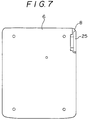
- Fig.7 is a bottom view of the recording and/or reproducing apparatus shown in Fig.1.
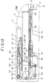
- Fig.8 is an exploded perspective view of the recording and/or reproducing apparatus shown in Fig.1.
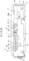
- Fig.9 is a right-hand side view showing a casing constituting of the main body of the recording and/or reproducing apparatus according to the present invention.
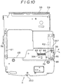
- Fig.10 is a bottom view showing a cover support plate constituting the recording and/or reproducing apparatus according to the present invention.
- Fig.11 is a left-hand side view of the cover support plate shown in Fig.10.
- Fig.12 is a left-hand side view showing an inner construction of the recording and/or reproducing apparatus in the ejecting state.
- Fig.13 is a left-hand side view showing an inner construction of the recording and/or reproducing apparatus in the stop state.
- Fig.14 is a left-hand side view showing an inner construction of the recording and/or reproducing apparatus in the stop state.
- Fig.15 is a plan view showing an inner construction of a mechanical chassis with the recording and/or reproducing apparatus in the stop mode.
- Fig.16 is a plan view showing an inner construction of the mechanical chassis with the recording and/or reproducing apparatus in the playback mode.
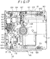
- Fig.17 is a plan view showing an inner construction of a mechanical chassis with the recording and/or reproducing apparatus in the recording mode.
- Fig.18 is a plan view showing a cartridge holder with the recording and/or reproducing apparatus in the stop mode and in the playback mode.
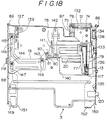
- Fig.19 is a plan view showing a cartridge holder with the recording and/or reproducing apparatus in the recording mode.
- Fig.20 is an enlarged exploded perspective view showing essential portions of an arrangement for retaining an upper lid of the recording and/or reproducing apparatus.
- Fig.21 is a front view showing a construction for retaining an upper lid of the recording and/or reproducing apparatus.
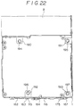
- Fig.22 is a plan view showing a main frame of the recording and/or reproducing apparatus.
- Fig.23 is a plan view showing an outer cover of the recording and/or reproducing apparatus.
- Fig.24 is a front view showing the outer cover of the recording and/or reproducing apparatus.
- Fig.25 is a front view showing the state of an upper lid being closed.
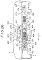
- Fig.26 is a front view showing the state of the upper lid which has been closed.
- Fig.27 is a front view showing the state in which retention of the upper cover has been released.
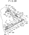
- Fig.28 is an enlarged perspective view showing a cartridge ejection mechanism.
- Fig.29 is right-hand side view showing the mounting stat between the mechanical chassis and the cartridge holder.
- Fig.30 is a right-hand side view schematically showing the state in which the cartridge holder is being rotated towards the mechanical chassis.
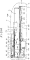
- Fig.31 is a longitudinal cross-sectional view showing a supporting structure of the mechanical chassis.
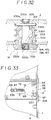
- Fig.32 is a longitudinal cross-sectional view showing a damper unit employed in the recording and/or reproducing apparatus according to the present invention.
- Fig.33 is a schematic enlarged plan view showing a member for suspending a cartridge holder.
- Fig.34 is a schematic enlarged plan view showing the member for suspending a cartridge holder.
- Fig.35 is a schematic enlarged side view showing the member for suspending a cartridge holder.
- Fig.36 is a block circuit diagram showing a controlling section of the. recording and/or reproducing apparatus according to the present invention.
- Fig.37 is a flow chart showing an operating procedure of the recording and/or reproducing apparatus according to the present invention.
- Fig.38 is a perspective view, as seen from an upper side, showing a disc cartridge enabling re-recording of information signals employed in the recording and/or reproducing apparatus according to the present invention.
- Fig.39 is a perspective view, as seen from an upper side, showing a replay-only disc cartridge employed in the recording and/or reproducing apparatus according to the present invention.
- Fig.40 is a perspective view, as seen from below, the disc cartridge shown in Fig.38.
- Fig.41 is a perspective view, as seen from below, the disc cartridge shown in Fig.39.
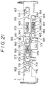
- Fig.42 is a longitudinal cross-sectional view showing a damper unit employed in the recording and/or reproducing apparatus according to the present invention.
- Fig.43 is a plan view showing a set screw constituting the damper unit.
- Fig.44 is aside view showing the set screw shown in fig.43.
- Fig.45 is a side view showing a shaft constituting the damper unit shown in Fig.43, with a portion thereof being broken away.
- the disc recording and/or reproducing apparatus includes a frame 1 constituting a main body of the apparatus and a base member 2 supported by the frame 1 in the floating state by plural damper units 14, as shown in Fig.8.
- a battery casing 8, an upper cover 5 and a lower cover 6 are mounted on the frame 1.
- a lid 700 having an upper cover 5 and a cover support plate 4 is rotatably mounted on the battery casing 8.
- the lid 700 is rotatably mounted on a main body of the apparatus made up of the frame 1, battery casing 8, outer cover 5 and the lower cover 6.
- the lid 700 opens or closes the upper side of the main body of the apparatus, as shown in Figs.9 and 12.
- a cartridge holder 3 is rotatably mounted on the upper surface of the base member 2.
- the key input unit 15 has a play button 28, a forward track jump button 31, a reverse tack jump button 30, a pause button 32, a stop button 29 and output sound volume adjustment buttons 33, 34, as shown in Fig.1.
- the display section 16 is constituted by a planar display device, such as a liquid crystal display device. On the display section 16 is displayed a variety of information data depending on the operating modes of the disc recording and/or reproducing apparatus.
- Another pushbutton switch 27, constituting the key input unit 15, is covered by a slide cover 26, mounted on the upper cover 7 slid towards the front side of the main body of the apparatus as indicated by arrow A in Fig.1.
- a CPU 338 as a control circuit is mounted, as shown in Fig.36.
- the key input unit 15 is electrically connected to the CPU 338.
- the CPU 338 is responsive to the input signals to effect driving control of a disc driving mechanism of the recording and/or reproducing unit provided on the base member 2.
- the magneto-optical disc 200 is comprised of a disc substrate formed of light-transmitting transparent synthetic resin material, such as polycarbonate, having a diameter of approximately 64 mm, and a signal recording layer of a magnetic material deposited thereon.
- the signal recording layer is locally heated to a temperature higher than the Curie temperature by a light beam radiated from a light source, such as a semiconductor laser, and converged on the recording layer.
- the information signals thus recorded may be read out by radiating a linear polarized light beam, such as a laser beam, on the signal recording layer, and detecting the return light from the magneto-optical disc 200.
- An optical disc 201 used for reproducing information signals, is comprised of a disc substrate, similar to that of the magneto-optical disc enabling re-recording of information signals, and a reflective layer of a metal material, such as aluminum, deposited thereon.
- the information signals recorded on the optical disc 200 may be read out by radiating a light beam on the pit string and detecting the return light from the optical disc by a photodetector, not shown.
- the magneto-optical disc 200 and the optical disc 201 are rotatably accommodated in main cartridge bodies 205, 216, respectively, for constituting disc cartridges, as shown in Figs.38 to 41.
- the cartridge main body 205 of the disc cartridge 220, housing the magneto-optical disc 200 for enabling both recording and playback of information signals, is formed substantially as a square having each side equal in length to the diameter of the magneto-optical disc 200.
- the cartridge main body 205 has an aperture 223 for the magnetic head on its upper major surface for partially exposing the signal recording surface of the magneto-optical disc 200 to outside across its inner and outer rims, as shown in Fig.38.
- the cartridge main body 205 has an aperture 222 for the optical pickup in a portion on its lower major surface facing the aperture 223, as shown in Fig.40. At a mid portion on the lower major surface is formed a chuck aperture 213.
- the aperture 223 for the magnetic head and the aperture 222 for the optical pickup, formed in the main cartridge body 205, are opened or closed by a shutter member 206 movably mounted on the main cartridge body 205.
- the shutter member 206 molded from a synthetic resin or bent from a metallic sheet, has a pair of shutter plate portions large enough to close the apertures 222, 223 and a connecting web portion interconnecting these shutter plate portions, and is substantially U-shaped in cross-section.
- the shutter member 206 is carried for movement along a lateral side of the main cartridge body 205 by having its connecting web portion engaged in a support groove 207 formed in the main cartridge body 205. That is, the shutter member 206 opens or closes the apertures 223, 222 by being moved along a lateral side of the main cartridge body 205.
- the main cartridge body 216 for the disc cartridge 220, housing the replay-only optical disc 201 is formed as a square having the length of each side substantially equal to the diameter of the optical disc 201 housed therein.
- the main cartridge body 216 has a substantially planar upper surface, that is an upper surface devoid of an aperture, as shown in Fig.39. It is in the lower surface of the main cartridge body 216 that the aperture 222 for the optical pickup 222 and the chuck aperture 213 are formed, as shown in Fig.41.
- the aperture 222 for the optical pickup formed in the cartridge main body 216 is opened or closed by a shutter member 217 movably mounted on the main cartridge body 216.
- the shutter member 217 molded from a synthetic resin or bent from a metallic sheet, has a pair of shutter plate portions large enough to close the aperture 222 for the optical pickup and a supporting portion interconnecting these shutter plate portions, and is substantially U-shaped in cross-section.
- the shutter member 206 is carried for movement along a lateral side of the main cartridge body 205 by having its supporting portion engaged in a support groove 207 formed in the main cartridge body 216. That is, the shutter member 217 opens or closes the aperture for the optical pickup 222 by being moved along a lateral side of the main cartridge body 205.
- Each of the shutter members 206, 217, provided respectively in the recording/reproducing disc cartridge 221 and the replay-only disc cartridge 220, is formed at a mid portion of the connecting web portion or the support portion with a shutter-closing opening 208 adapted for being engaged by a shutter-closing operating member provided on the disc recording/reproducing apparatus.
- each of the recording/reproducing disc cartridge 221 and the replay-only disc cartridge 220 is formed a circular chuck opening 204 for the magneto-optical disc 200 ad the optical disc 201, respectively.
- Each of the magneto-optical disc 200 ad the optical disc 201 has a chuck plate 202 mounted thereon for closing the chuck aperture 204.
- the chuck plate 202 is formed of a magnetic metal material, such as iron or stainless steel, as a disc large enough to close the chuck aperture 204.
- the chuck aperture 204 and the chuck plate 202 are exposed to outside of the cartridge main bodies 205, 216 via the chuck aperture 213.
- the positioning opening 209 is formed near the corner towards the aperture 222 for the optical pickup and is formed as an oblong hole having its longer axis extending in the fore and aft direction.
- the other positioning opening 210 is located near the other corner towards the aperture 222 for the optical pickup and is formed as a circular hole.
- Plural discriminating openings 224 are formed on the lateral sides of the lower surfaces of the cartridge main bodies 205, 216 to opposite to the shutter members 206, 217. These discriminating openings 224 are used for discriminating the type or the state of the disc accommodated in the cartridge main bodies 205, 216, that is whether or not the information signals can be recorded thereon.
- a mistaken recording inhibiting member 214 is provided in the cartridge main body 205 of the recording/reproducing disc cartridge 220 so as to be partially exposed to the above-mentioned opposite lateral side, as shown in Fig.38.
- the mistaken recording inhibiting member 214 is movable for opening and closing the discriminating openings 224 for changing over the recordable/unrecordable discriminating state.
- the lower lateral sides of each of the cartridge main bodies 205, 216 are formed with engagement recess 212 engaged by a portion of a loading mechanism during loading of the disc cartridges 220, 221, as shown in Figs.40 and 41.
- a magneto-optical disc discriminating recess 211 In the lateral surface perpendicular to the lateral surface of the cartridge main body 205 of the recording/reproducing disc cartridge 220 mounting the shutter member 206, there is formed a magneto-optical disc discriminating recess 211, as shown in Fig.40. In the lateral surface perpendicular to the lateral surface of the cartridge main body 216 of the replay-only disc cartridge 221 mounting the shutter member 217, there is formed a optical disc discriminating recess 218, as shown in Fig.41.
- the magneto-optical disc discriminating recess 211 and the optical disc discriminating recess 218 are of different depths and hence the magneto-optical disc 200 may be discriminated from the optical disc 200 based upon such difference in depth.
- the above described disc cartridges 220, 221 are inserted into and taken out from the disc recording/reproducing apparatus with the direction parallel to the direction of movement of the shutter members 206, 217, as indicated by arrow E in Figs.38 and 39, as the introducing direction.
- the frame 1 of the recording and/or reproducing apparatus is formed as a framework delimiting the peripheral wall of a casing constituting the main body of the apparatus, as shown in Figs.21 and 22.
- the battery casing 8 is formed of a synthetic material to a size capable of holding a battery 225 therein, and is screwed to the rear side of the frame 1.
- the battery casing 8 is formed in its lateral surface with an opening/closing lid 25 for opening or closing a battery inserting/removing opening, as shown in Fig.8.
- the battery 225 is introduced into or removed from the battery inserting/removing opening.
- the battery 25 may be a rechargeable secondary battery, such as a lithium ion battery, a lithium hydrogen battery or a nickel-cadmium (Ni-Cd) battery, enclosed in a container casing. Positive and negative terminals are provided on the outer surface of the container casing. In the interior of the battery casing 8, there is mounted a power source terminal contacted by each electrode terminal of the battery 225.
- the outer cover 5, constituting the casing along with the frame 1, is formed of, for example, synthetic material, and is substantially frame-shaped, as shown in Figs.23 and 34.
- the outer cover 5 is mounted on the frame 1 for sheathing the outer peripheral part of the frame 1 on the front surface of the outer cover 5, there are movably mounted an ejection knob 17 engaged with an engagement lug 175 provided on one end of the ejection lever 116 and a recording knob 18 engaged by an abutment lug 341 provided on the opposite side of the recording lever 186.
- the ejection knob 17 when slid causes a sliding of the ejection lever 116.
- the recording knob 18 when slid causes a sliding of the recording lever 186.
- the recording knob 18 forms a part of the key input section 15 and thrusts a recording start switch, not shown, connected to the CPU 338, via the recording lever 186.
- the lower cover 6, constituting the casing along with the frame 1, is formed of metal as a substantially planar plate, as shown in Figs.3 to 7.
- the lower cover is screwed to the lower lateral side of the frame 1 and constitutes the lower surface of the outer casing of the main body of the apparatus.
- connection jacks 36 to 40 for input/output of information signals, as shown in Figs.3 and 4. These connection jacks 36 to 40 are connected to an electronic circuit formed on an electronic circuit substrate.
- the base member 2 is formed of metal or the like material substantially as a planar plate, as shown in Figs.15 to 17.
- a disc driving unit 339 On the base member 2 is formed a disc driving unit 339.
- a spindle motor 89 At a mid portion on the lower surface of the base member 2 is mounted a spindle motor 89 with its driving shaft directed upwards.
- the driving shaft of the spindle motor 89 is projected above the base member 2 via a through-hole formed at a mid portion of the base member 2.
- a disc table 11 is mounted on the driving shaft of the spindle motor 89.
- the disc table 11 is formed substantially as a disc on the upper surface of which is formed a frusto-conical centering member engaged in a chuck hole of the magneto-optical disc 200 or the optical disc 201.
- the centering member On the upper surface of the disc table 11 provided with the centering member, there is provided a magnet for attracting a chuck plate 202.
- the centering member When the mid portion of the magneto-optical disc 200 or the optical disc 201, inclusive of the chuck hole 204, is set on the disc table 11, the centering member is fitted in the chuck hole 204, at the same time as the chuck plate 202 is attracted by the magnet for holding the magneto-optical disc 200 or the optical disc 201 in position.
- the magneto-optical disc 200 or the optical disc 201 is positioned with the center of the chuck hole 204 aligned with the center axis of the driving shaft of the spindle motor 89.
- the spindle motor 89 produces the rotation of the magneto-optical disc 200 or the optical disc 201 along with the disc table 11.
- the optical pickup 10 is mounted on the base member 10 having an optical block within which there are enclosed a semiconductor laser as a light source, a light receiving element such as a phototransistor, various optical devices for guiding a light beam outgoing from the semiconductor laser or an objective lens 130.
- the optical pickup 10 converges the light beam emanated from the semiconductor laser via the optical devices and the objective lens 130 on the signal recording layer of the magneto-optical disc 200 or the optical disc 201.
- the optical pickup 10 also guides the return light of the light beam radiated on the magneto-optical disc 200 or the optical disc 201 to the light receiving element via the objective lens 130 and the optical devices for detection by the light receiving element.
- the optical pickup 10 detects the light volume and the angle of rotation of the polarized light from the return light of the magneto-optical disc 200 or the optical disc 201 in order to read information signals recorded on the magneto-optical disc 200 or the optical disc 201.
- the optical pickup 10 is positioned on one side of the spindle motor 89 and movably mounted via a pair of guide shafts 122, 123 parallel to each other on the lower surface of the base member 2, as shown in Figs.15 to 17.
- the optical pickup 10 is guided by these guide shafts 122, 123 so as to be moved towards and away from the spindle motor 89.
- the optical pickup 10 has the objective lens 130 exposed to above the base member 2 via a through-hole formed in the base member 2.
- the objective lens 130 faces the signal recording surface of the magneto-optical disc 200 or the optical disc 201. That is, the optical pickup 10 takes charge of radiation of the light beam for recording the information signals on the magneto-optical disc 200 held by and rotated on the disc table 11 and the readout of information signals recorded on the magneto-optical disc 200 or the optical disc 201.
- an optical pickup feed motor 124 for feeding the optical pickup 10 under guidance by the guides shafts 122, 123, as shown in Figs.15 to 17.
- a driving gear 125 is mounted on a driving shaft of the optical pickup feed motor 124.
- the driving gear 125 meshes with a speed-reducing transmission gear 126 rotatably supported on the lower surface of the base member 2.
- the speed-reducing transmission gear 126 meshes with a follower gear 127 mounted on one end of a screw shaft 121 rotatably mounted on the lower surface of the base member 2 parallel to the guide shafts 122, 123, and causes the screw shaft 121 to be rotated about its axis via the follower gear 127.
- the screw shaft 121 has a male threaded portion on its outer peripheral surface meshing with the optical block of the optical pickup 10. That is, when the pickup feed motor 124 is run in rotation, the screw shaft is run in rotation for moving the optical pickup 10 along the guide shafts 122, 123.
- an inner peripheral position detection switch 128 which is pushed and actuated by the optical block of the optical pickup 10 when the optical pickup 10 is closest to the spindle motor 89 within the range of movement of the optical pickup 10, that is when the optical pickup 10 is at the radially innermost position of the magneto-optical disc 200 or the optical disc 201, as shown in Figs.15 to 17.
- paired positioning pins that is a forward positioning pin 70 and a rear positioning pin 342, at offset positions near the forward and rear edges of the base member 2, as shown in Figs.15 to 17.
- the forward positioning pin 70 is substantially frusto-conical and tapered towards its distal end, as shown in Fig.20.
- the rear positioning pin 342 is similarly substantially frusto-conical in profile.
- a height position setting boss 71 At an offset position near the forward edge of the base member 2, there is formed a height position setting boss 71, as shown in Figs.12 and 20.
- the height position setting boss 71 is formed by extending a part of the base member 2 upwards.
- the height position setting boss 71 is caused to bear against the lower major surface of the cartridge main body 205 or 216 set on the base member 2 for positioning the cartridge main body 205 or 216.
- a cartridge loading detection switch 72 Below the height position setting boss 71 is mounted a cartridge loading detection switch 72.
- the cartridge loading detection switch 72 has a pusher 73 projected above the upper surface of the height position setting boss 71 via a through-hole formed in the height position setting boss 71.
- the cartridge loading detection switch 72 When the lower major surface of the cartridge main body 205 or 216 is caused to bear against the upper surface of the height position setting boss 71, the cartridge loading detection switch 72 has its pusher 73 thrust by the major surface for detecting that one of the disc cartridges 220, 221 has now been loaded.
- discrimination switches 107, 108 for detecting the discrimination holes 224 formed in the disc cartridge 220 or 221. These discrimination switches 107, 108 are thrust when the discrimination holes 224. are of shallow depth and are not thrust if these holes are of deeper depth.
- the cartridge main body 205 or 216 is positioned by the positioning pins 70, 342 and the height position setting boss 71, both in the horizontal direction and in the height direction, while the magneto-optical disc 200 or the optical disc 201 is held in position on the disc table 11.
- the cartridge loading detection switch 72 detects the loading of the disc cartridge 220 or 221, while the discrimination switches 107, 108 detect the state of the discrimination holes 224.
- the cartridge loading detection switch 72 is connected as a switch A to the CPU 338, as shown in Fig.36.
- the magneto-optical disc 200 or the optical disc 201 is enabled to be rotated within the cartridge main body 205 or 216 without being contacted with the inner wall of the cartridge main body 205 or 216.
- a magnetic head 13 On the optical pickup 10 is mounted a magnetic head 13 via a connecting arm 12, a magnetic head supporting plate 132 and a magnetic head supporting arm 77, as shown in Figs.12 to 14, 18 and 19.
- the connecting arm 12 is substantially L-shaped and has its one end mounted on the optical block of the optical pickup 10 by set screws 119, 119, while having its other end directed upwards at the rear end of the optical block, as shown in Fig.13.
- the other end of the connecting arm 12 is located more rearwardly than the rear edge of the base member 2, as shown in Figs.18 and 19, and is moved together with the optical pickup 10 without being abutted against the base member 2.
- the connecting arm 12 has its other end projected above the upper surface of the base member 2. In the vicinity of the other upper end of the connecting arm 12 is rotatably mounted a rear edge portion of the magnetic head supporting plate 132 via a pivot 74.
- the magnetic head supporting plate 132 has its forward side directed forwards, and has the forward edge rotatable in a direction towards and away from the base member 2, as shown in Figs.12 to 14.
- a positioning lug 87 is projected from near the other end of the connecting arm 12. The positioning lug 87 is located above the positioning arm 75 and positioned by having its downward travel inhibited on abutment against the end region of the positioning arm 75, as shown in Figs.12 to 14.
- a magnetic head supporting arm 77 is supported by having its distal end directed forwards and has a portion near its distal end bent in the lateral direction. as shown in Figs.12 to 14.
- a gimbal spring 79 has its proximal end mounted on the magnetic head supporting plate 132.
- the magnetic head 13 is mounted on the distal end of the gimbal spring 79, part of which is bent to form a retention support 117.
- the retention support 117 is engaged with the bent portion in the vicinity of the distal end of the magnetic head supporting arm 77, as shown in Figs.12 to 14.
- the magnetic head 13, thus supported, is located above the objective lens 130 of the optical pickup 10, and faced by the optical pickup 10.
- the magnetic head 13 is also movable in the up-and-down direction for being contacted with or separated from the base member 2, by the magnetic head supporting plate 132 being rotated relative to the connecting arm 12.
- the magnetic head 13 is also positioned in the downward direction by abutment of the positioning lug 87 with the positioning arm 75.
- a torsion coil spring 76 is placed around one end of the pivot 74.
- the torsion coil spring 76 has its coil part interposed between the proximal portion of the positioning arm 75 and the magnetic head supporting plate 132, while having its arm sections retained by the positioning arm 75 and the magnetic head supporting plate 132, as shown in Figs.12 to 14.
- the torsion coil spring thrusts magnetic head supporting plate 132 towards the opposite lateral side of the connecting arm 12 for lateral positioning of the magnetic head supporting plate 132, while rotationally biasing the magnetic head supporting plate 132 relative to the connecting arm 12 in a direction in which the magnetic head 13 is moved downwards.
- the magnetic head 13 is fed with electric current via a flexible printed circuit board 133 extended between the proximal ends of the magnetic head 13 and the magnetic head supporting arm 77.
- the cartridge holder 3 On the upper surface of the base member 2 is mounted a cartridge holder 3 into which is introduced the disc cartridge 220 or 221.
- the cartridge holder 3 has a top plate, left-hand and right-hand sidewall sections 149, 150 depending from both lateral side edges of the top plate and support pieces 151, 152 bent inwards from the lower ends of the sidewall sections, as shown in Figs.12 to 14, 18 and 19.
- the cartridge holder 3 is formed by bending a one-piece metal sheet material.
- the disc cartridge 220 or 221 is introduced from the forward side opening into a space between the lower sidewall sections 149, 150 below the top plate in a direction indicated by arrow in Fig.8 so as to be held and supported at lateral sections of the lower major surface thereof.
- the disc cartridge 200 or 201 has the lower major surface facing downwards, substantially in its entirety, with the chuck aperture 213, aperture for the optical pickup 222, positioning holes 209, 210 and the discriminating holes 224 facing the lower side of the cartridge holder 3.
- a shutter opening piece 136 directed towards the inner side of the cartridge holder 3, as shown in Figs.18 and 19.
- the shutter opening piece 136 is caused to bear against the forward end face of the connecting web portion or supporting portion of the shutter member 206 or 217 for moving the shutter member 206, 217 as the disc cartridge 220 or 221 is introduced into the cartridge holer 3 for opening the apertures 213, 222, 223 formed in the cartridge main body 205 or 216.
- the shutter closure member 135 is engaged in a shutter closure opening 208 of the shutter member 206 or 217 and, when the disc cartridge 220 or 221 is extracted from the cartridge holder 3, shifts the shutter member 206 or 217 in a direction of closing the apertures 213, 222, 223 formed in the cartridge main body 205 or 216.
- a pair of retention springs 134, 137 are mounted on both sides on the rear lateral side of the top plate of the cartridge holder 3.
- Each of the retention springs 134, 137 has its proximal end secured to the upper surface of the top plate while having its proximal end directed towards the rear.
- the foremost parts of these retention springs 134, 137 are projected via through-holes 138, 139 formed in both sides on the rear lateral side of the top plate towards below the top plate, that is into the inside of the cartridge holder 3, as shown in Figs.18 and 19.
- the retention springs 134, 137 thrust and support the upper major surface of the disc cartridge 220 or 221 introduced into the cartridge holder 3.
- left-hand and right-hand side pivots 86, 86 On both rear lateral sides of the cartridge holder 3 are mounted left-hand and right-hand side pivots 86, 86 having their axes running parallel to the rear edge of the cartridge holder 3. These pivots 86, 86 are passed through left-hand and right-hand side bearing members 98, 90 mounted near the rear side of the base member 2, as shown in Figs.15 to 17, so that the cartridge holder 3 is supported for rotation about these pivots 86, 86 as the center of rotation.
- the disc cartridge 220 or 221 When the disc cartridge 220 or 221 is introduced into and held by the cartridge holder 3 which is rotated upwards so as to be spaced apart from the base member 2, as shown in Fig.12, and subsequently the cartridge holder 3 is rotated downwards as shown in Fig.13 so as to be set on the base member 2, the disc cartridge 220 or 221 held by the cartridge holder is loaded in the cartridge loading position on the base member 2.
- the disc cartridge 220 or 221, loaded on the base member 2 is thrust towards and supported by the retention springs 134, 137.
- the magnetic head supporting plate 132 and the magnetic head supporting arm 77 are positioned above the cartridge holder 3.
- thee is bored a through-hole 140 in register with the range of possible movement of the magnetic head supporting arm 77 and the gimbal spring 79 accompanying the movement of the optical pickup 10, as shown in Figs.18 and 19. That is, the magnetic head 13 faces the upper surface of the disc cartridge 220 or 221 held within the cartridge holder 3 via the through-hole 140.
- a first click stop link 24 On a lateral surface, that is an outer surface of the sidewall section 150 of the cartridge holder 3, a first click stop link 24 has its proximal end rotatably mounted via a pivot 318, as shown in Figs.28 to 30.
- the first stop clink link 24 has its distal end directed forwards and is rotatably mounted on a click stop lever 23 movably mounted near a lateral edge on the upper surface of the base member 2.
- the click stop lever 24 has its longitudinal direction as the fore-and-aft direction and has a support pin 322 set on the base member 2 introduced into an oblong hole 323 having its long axis extending in the longitudinal direction so that the click stop lever 24 is slidable in the fore-and-aft direction.
- the click stop lever 23 has a supporting piece 320 bent upwards and the first click stop link 24 has its distal end mounted via a pivot 328 relative to the supporting piece 320. The foremost end of the first stop link 24 beyond the pivot 328 is formed with a click stop protrusion 319, while the supporting piece 320 is formed with a click stop groove 321.
- the click stop lever 23 When the cartridge holder 3 is rotated upwards as indicated by arrow G in Fig.29, the click stop lever 23 is slid rearwards via the first click stop link 24, as indicated by arrow I in Fig.29.
- the click stop boss 319 is then moved from above the supporting piece 320 as indicated by arrow H in Fig.29 to laterally of the supporting piece 320 while elastically deforming the distal end of the first click stop link 24.
- the click stop boss 319 When the cartridge holder 3 is rotated halfway, the click stop boss 319 is engaged in the click stop groove 321.
- the cartridge holder 3 is held at this time at a position spaced apart from the base member 2, as shown in Fig.30.
- the disc cartridge ejection mechanism On the rear side on the upper surface of the base member 2, there is mounted a disc cartridge ejection mechanism for ejecting the disc cartridge 220 or 221 so far held in the cartridge holder 3 in a forward direction.
- the disc cartridge ejection mechanism has a cartridge ejection lever 302 rotatably mounted on the rear side of the base member 2 and an ejection lever lock lever 309. for locking the cartridge ejection lever 302 at the rear position, as shown in Fig.28.
- the cartridge ejection lever 302 has its proximal end projected below the base member 2 via a through-hole 304 formed near the rear edge of the base member 2 and has its proximal end supported via a pivot 303 for rotation relative to the lower surface of the base member 2.
- An engagement lug 307 is formed on the lower edge of a mid portion of the cartridge ejection lever 302 for extending downwards into an arcuate slit 308 formed in the base member 2.
- the cartridge ejection lever 302 has its range of rotation delimited by a slit 308 so that it is rotatable from a position in which its distal end is directed obliquely forwards to a position in which the distal end is directed laterally along the rear edge of the base member 2.
- a tension coil spring 129 is mounted between a spring retainer 305 provided on the proximal end of cartridge ejection lever 302 and a spring retainer lug 306 provided on the lower surface of the base member 2.
- the tension coil spring 129 rotationally biases the distal end of the cartridge ejection lever 302 in a forward direction as indicated by arrow K in Fig.28.
- the ejection lever lock lever 309 is supported laterally slidably by supporting pins 310, 311 implanted on the upper surface of the base member 2, as shown in Fig.28.
- the ejection lever lock lever 309 has its one end facing the rear end of a lock release spring 324 mounted on the click stop lever 23 for being extended rearwards from the click stop lever 23, while having its other end facing the rear end of a slit 308 engaged by the engagement lug 307.
- the lock release spring 324 has its rear end elastically deflectable upwards and has its rear end portion located on the upper surface of the ejection lever lock lever 309.
- the lock release lever 324 has its rear end as a tapered portion 325 inclined towards one lateral side and having a cut-out 326 opened towards one lateral side and an inclined edge 327 provided at the rear edge of the cut-out 326.
- the other end of the ejection lever lock lever 309 is formed with a tapered portion 316 inclined towards the engagement lug 307.
- the ejection lever lock lever 309 is biased towards the opposite lateral side as indicated by arrow M in Fig.28, that is towards the slit 308, by a tension coil spring 315 mounted between a spring retainer 313 and a spring retainer lug 313 provided on the base member 2.
- the cartridge ejection lever 302 In an initial state of the cartridge ejection mechanism, in which the cartridge holder 3 is positioned towards the base member 2, as shown in Fig.28, the cartridge ejection lever 302 is located forwards, while the lock release spring 324 and the clock stop lever 23 are also located forwards.
- the lock release spring 324 When the cartridge holder 3 is rotated upwards as indicated by arrow N in Fig.28, the lock release spring 324 is moved rearwards as indicated by arrow P in Fig.28. At this time, the lock release spring 324 thrusts the lock release pin 317 towards one lateral side by its tapered portion 325 for sliding the ejection lever lock lever 309 towards a lateral side against the bias of the tension coil spring 315.
- the lock release spring 324 shifts the cut-out 326 to a position registering with the lock release pin 317.
- the ejection lever lock lever 309 causes the lock release pin 317 to be intruded into the cut-out 326 so that the initial state is again established.
- the disc cartridge 220 or 221 When the disc cartridge 220 or 221 is introduced into the cartridge holder 3, the disc cartridge 220 or 221 thrusts the foremost part of the cartridge ejection lever 302 for rotating the cartridge ejection lever 302 in a direction opposite to that indicated by arrow K in Fig.28 against the bias of the tension coil spring 129.
- the engagement lug 307 thrusts the tapered portion 316 formed at the opposite end of the ejection lever lock lever 309 for sliding the ejection lever lock lever 309 towards the above-mentioned lateral side.
- the ejection lever lock lever 309 is slid once towards the above-mentioned lateral side as indicated by arrow Q in Fig.28.
- the engagement lug 307 reaches a position further rearward than the opposite lateral side of the ejection lever lock lever 309, so that the initial position is again established.
- the cartridge ejection lever 302 is locked at the rear position.
- the lock release lever 324 When the cartridge holder 3 is rotated towards the base member 2, the lock release lever 324 is moved forwards as it is elastically deformed towards the upper side, with the inclined edge 327 in sliding contact with the upper end of the lock release pin 317, as shown in Fig.30. Consequently, the ejection lever lock lever 309 is not slid. If the cartridge holder 3 holds at this time the disc cartridge 220 or 221, the disc cartridge 220 or 221 is held within the cartridge holder 3 and moved in this state towards the base member 2.
- the ejection lever lock lever 309 When the cartridge holder 3 holding the disc cartridge 220 or 221 is rotated upwards away from the base member 2, the ejection lever lock lever 309 is slid once towards the above-mentioned lateral side during the rotation of the cartridge holder 3 as indicated by arrow Q in Fig.28. When the ejection lever lock lever 309 is slid in this manner towards the above-mentioned lateral side, the ejection lever lock lever 309 is unlocked so that the cartridge ejection lever 302 is rotated forwards as indicated by arrow K in Fig.28, under the bias of the tension coil spring 129, for ejecting the disc cartridge 220 or 221 forwardly of the cartridge holder 3.
- the lifting of the magnetic head 13 is taken charge of by a magnetic head lifting plate 20 mounted on the upper surface of the cartridge holder 3 and a magnetic head lifting lever 94 mounted on the lower surface of the base member 2 for sliding a transmission lever 19.
- the magnetic head lifting plate 20 is mounted below the magnetic head supporting arm 77 and the gimbal spring 79 for closing the rear portion of a cut-out 140, as shown in Figs.12 to 14, 18 and 19.
- the magnetic head lifting plate 20 has its rear edge portion rotatably supported via pivot 78 relative to the top plate of the cartridge holder 3 so that its forward side is movable in the vertical direction.
- the magnetic head lifting plate 20 thrusts the gimbal spring 79 towards the magnetic head supporting arm 77, while rotating the gimbal spring 79 and the magnetic head supporting arm 77 about the pivot 74 as the center of rotation, as shown in Figs.12 an 13.
- the magnetic head lifting plate 20 When rotated downwards, the magnetic head lifting plate 20 has a portion of its forward edge abutted against the top plate of the cartridge holder 3 so as to be positioned substantially in flush with the top plate. At this time, the magnetic head supporting arm 77 is rotated downwards until the positioning lug 87 is caused to bear against the positioning arm 75. On the other hand, the gimbal spring 79 is lowered below the magnetic head supporting arm 77 until an engagement support 117 is hung from the bent distal end of the magnetic head supporting arm 77.
- the distance L1 from the lower surface of the magnetic head 13 as far as the upper surface of the magnetic head supporting arm 77 as shown in Fig.13 is shorter than the distance L1 from the lower surface of the magnetic head 13 as far as the upper surface of the magnetic head supporting arm 77 when the magnetic head lifting plate 20 has been rotated downwards, as shown in Fig.14.
- the magnetic head lifting plate 20 has its proximal end rotationally biased downwards by the foremost part of a plate spring 141 mounted by a mounting pin 142 on the upper surface of the cartridge holder 3. That is, the plate spring 141 has its foremost part set on the magnetic head lifting plate 20, as shown in Fig.13.
- the transmission lever 19 is mounted on the opposite lateral side on the upper surface of the cartridge holder 3 for sliding in the fore-and-aft direction, as shown in Figs.13 and 14.
- the transmission lever 19 has parallel support grooves 146, 147 engaged by support pins 143, 144, projected on the upper surface of the cartridge holder 3, respectively.
- the transmission lever 19 has a lifting lug 80 at its lateral side, that is a portion thereof located at a mid part of the cartridge holder 3 for facing the opposite lateral side of the magnetic head lifting plate 20.
- the forward end of the lifting lug 80 is a tapered portion 81 inclined upwards.
- the lower surface on the opposite lateral side of the magnetic head lifting plate 20 is formed with an inclined surface 82 registering with the lifting lug 80.
- the inclined surface 82 is formed as a rearwardly inclined tapered portion by having a portion of the magnetic head lifting plate 20 segmented and bent in the upward direction.
- the transmission lever 19 When shifted towards the front side from the rear side, the transmission lever 19 causes the lifting lug 80 to be intruded into a space between the magnetic head lifting plate 20 and the upper surface of the cartridge holder 3 as the tapered portion 81 has a sliding contact with the inclined surface 82 of the magnetic head lifting plate 20.
- the magnetic head lifting plate 20 is rotated upwards against the bias of the plate spring 141, as shown in Fig.13.
- the transmission lever 19 causes the lifting lug 80 to be receded rearwards via a space between the magnetic head lifting plate 20 and the upper surface of the cartridge holder 3 as the tapered portion 81 has a sliding contact with the inclined surface 82 of the magnetic head lifting plate 20.
- the transmission lever 19 has a connecting arm 83 at its opposite lateral side for depending towards the base member 2, as shown in Figs.12 to 14.
- the connecting arm 83 is protruded below the base member 2 via a through-hole 84 formed near the opposite lateral side of the base member 2.
- a magnetic head lifting lever 94 is mounted on the opposite lateral side on the lower surface of the base member 2 for sliding in the fore-and-aft direction, as shown in Figs.15 to 17.
- the magnetic head lifting lever 94 has parallel support grooves 98, 99 engaged by support pins 96, 97 set upright on the lower surface of the mechanical chassis 2, respectively.
- the magnetic head lifting lever 94 is moved in the fore-and-aft direction, responsive to the operating mode of the recording and/or reproducing apparatus by a stepping motor 85 controlled by the CPU 338.
- the stepping motor 85 is mounted at a rear portion on the lower surface of the base member 2.
- a driving gear 91 is mounted on a driving shaft of the stepping motor 85.
- the driving gear 91 meshes with a first transmission gear 92 rotatably supported on the lower surface of the base member 2.
- the first transmission gear 92 meshes with a worm wheel of a second transmission gear 93 rotatably mounted on the lower surface of the base member 2.
- the second transmission gear 93 has a pinion gear meshing with a rack gear 131 provided on the magnetic head lifting lever 94.
- the magnetic head lifting lever 94 is moved in the fore-and-aft direction under the driving force of the stepping motor 85 which is driven by being fed with driving pulses from the CPU 338 and thereby run in rotation an angle corresponding to the number of supplied pulses.
- the rear end of the magnetic head lifting lever 94 has an engagement opening 114 in register with the through-hole 84. In the engagement opening 114 is engaged the connecting arm 83 of the transmission lever 19 via the through-hole 84.
- the transmission lever 94 is slid in the fore-and-aft direction, the transmission lever 19 is moved in the fore-and-aft direction on the cartridge holder 3. Since the magnetic head lifting plate 20 is additionally rotated, the magnetic head 13 is lifted in an up-and-down direction.
- the connecting arm 83 is formed substantially arcuately about the pivot 86 of the cartridge holder 3 as the center of the arc, such that the connecting arm 83 is perpetually engaged in the engagement opening 114 even when the cartridge holder 3 is rotated about the pivot 86 as the center of rotation.
- a forwardly directed planar switch actuating piece 110 On the lower surface of the base member 2, there is mounted, in register with the switch actuating piece 110, a detection switch 109 for detecting the initial position of the magnetic head lifting lever 94.
- the initial position detection switch 109 is thrust by the switch actuating piece 110 when the magnetic head lifting lever 94 is moved to the forward initial position, and transmits to the CPU 338 a detection signal indicating that the lever 94 is in its initial position.
- the transmission lever 19 has been shifted to its initial position, so that the magnetic head 13 is held at its upper position.
- the position of the magnetic head lifting lever 94 may be found by counting the number of pulses supplied to the stepping motor 85 after outputting of the detection signals from the initial position detection switch 109.
- the opposite lateral side of the magnetic head lifting lever 94 is formed with a retention protrusion 111 which is extended towards a lateral guide portion, as shown in Figs.15 to 17.
- the retention protrusion 111 faces the upper side via a through-hole 112 formed near the opposite lateral side of the base member 2.
- a retention pawl 88 is formed at the lower edge of the sidewall section 149 of the cartridge holder 3, as shown in Figs.18 and 19.
- the retention pawl 88 is hook-shaped, that is, its lower end projected towards the lower side is bent inwards, so that, when the cartridge holder 3 is rotated downwards and set on the base member 2, the retention pawl 88 is projected below the base member 2 via the through-hole 112.
- the retention pawl 88 When protruded into the through-hole 112, the retention pawl 88 is positioned at back of the retention protrusion 111 should the magnetic head lifting lever 94 be at its initial position. When the retention pawl 88 is protruded into the through-hole 112 and the magnetic head lifting lever 94 is moved rearwards, the retention pawl 88 is retained by the retention protrusion 111, as shown in Fig.14, so that extrication from the through-hole 112 and upward movement of the retention pawl 88 is inhibited. That is, when the magnetic head lifting lever 94 is slid rearwards after rotation towards the base member 2, the retention pawl 88 is retained by the retention protrusion 111 for inhibiting the separating movement from the base member 2.
- the base member 2 is supported in a floating fashion relative to the frame 1, as mentioned hereinabove. That is, the base member 2 is supported by a damper unit 14 by each of four support pieces 190 to 193 projected towards the inner side of the frame 1, as shown in Fig.22.
- the damper unit 14 has a shaft 330 set for depending from the lower surface of the base member 2, as shown in Fig.32.
- the shaft 330 has a first flange 331 at its upper proximal end in Fig.32 towards the base member 2, and also has a second flange 332 at its distal end shown at a lower mid portion in Fig.32.
- the shaft 330 has its proximal end portion as a mounting portion 330a for mounting on the base member 2.
- the mounting portion 330a has a caulking recess 330c formed axially from its proximal end.
- the mounting portion 330a is introduced into a mounting opening in the base member 2 and subsequently mounted on the base member 2 by a caulking consisting in deforming the periphery of the caulking recess 330c outwards.
- a first flange 331 is caused to bear against the base member 2.
- the portion of the shaft 330 beyond the first flange 331 is a columnar-shaped pivot 330b.
- the distal end of the pivot 330b is formed with a female thread along its axis.
- a second flange 332a is formed as a head of a set screw 332 having a center threaded portion 332a and is mounted on the distal end of the pivot 330b by the threaded portion 332c being engaged with the threaded portion 332a of the shaft 330.
- a cross-shaped slot 332b engaged by a screwdriver is formed on the side of the head 332a opposite to the side having the threaded portion.
- the damper 334 is substantially cylindrically-shaped and formed of a viscoelastic material, such as butyl rubber.
- the damper has a center hole passed through by the pivot 330b of the shaft 330 and has upper and lower ends abutted against the first flange 331 and the second flange 332a.
- the damper 334 has an engagement groove encircling the damper 334 engaged by the inner periphery of supporting holes 194 to 197 bored in the supporting lugs 190 to 193 formed in the frame 1.
- the damper 334 absorbs vibrations transmitted from the frame 1 and prevents the vibrations from being transmitted to the base member 2.
- the damper unit 14 has a compression coil spring 333 which is fitted on the outer side of the damper 334 in order to function as a first elastic member interposed between the lower surface of the base member 2 and the upper surfaces of the supporting pieces 190 to 193 of the frame 1.
- the compression coil spring 333 thrusts the base member 2 upwards by its resiliency.
- the end of the compression coil spring 333 towards the base member 2 is fitted on the outer side of the first flange 331.
- the pivot 330b has a reduced-diameter portion 330f in register with the frame 1 on the outer periphery for assuring the range of possible movement relative to the shaft 330 of the frame 1 in a direction perpendicular to the axis of the shaft 330 accompanying the deformation of the damper 334.
- the outer periphery of he first flange 331 is conically-shaped so as to be reduced in diameter towards the base member 2 in order to prevent detachment of the coil spring 333.
- the cover support plate 4 constituting the lid 700 On the lower surface of the cover support plate 4 constituting the lid 700 are mounted the proximal ends of a pair of spring plates 61, 62, as second elastic members, with the distal ends directed downwards, as shown in Fig.31.
- the cover support member 4 is secured to the frame 1 in the closed state of the lid, as described subsequently, the base member 2 and the cartridge holder 3 are supported by being clamped by the four damper units 14 and the spring plates 61, 61 from the up-and-down direction indicated by arrows S1, S2 shown in Fig.31.
- the height position of the base member 2 is a counterbalanced position in which the coiling force of the compression coil spring 333 of each damper unit 14, the recoiling force of the spring plates 61, 62 and the weight of the base member 2 counterbalance one another.
- the present disc recording and/or reproducing apparatus it becomes possible to reduce the resonant frequency f0 of the vibrating system including the base member 2 and the cartridge holder 3 and hence to achieve sufficient absorption of the vibrations by the damper units 14.
- the damper 334 undergoes less deformation caused by its supporting the base member 2, so that it is less susceptible to cracking and hence improved durability may be achieved.
- the base member 2 and the cartridge holder 3 are supported as they are clamped between the damper units 14 and the spring plates 61, 62, it becomes possible to maintain the neutral position (the position in the stationary state) and the relative position with respect to the frame 1.
- the thrusting force of the disc cartridge 220 or 221 may be on the order of 200 gf.
- the foremost parts of the spring plates 61, 62 may be fitted with vibration absorbing members of, for example, rubber, interposed between the spring plates 61, 62 and the upper surface of the cartridge holder 3.
- the inner side of the outer cover 5 is formed with an abutting piece 198, as shown in Fig.23.
- the abutment piece 198 is intruded into the inside of the frame 1.
- the abutment piece 198 is positioned above the base member 2 for restricting the range of upward movement of the base member 2. Consequently, when lid 700 is rotated upwards for opening the upper surface of the main body of the apparatus, the base member 2 is biased upwards under the bias of the compression coil spring 333 of each of the damper units 14, and is positioned by being caused to bear at its lateral edge portions against the abutment piece 198.
- Fig.42 shows a modification of the damper unit 14 adapted for supporting the base member 2 by the frame 1 in a floating manner.
- the damper unit 14 has a shaft 330 set in a depending fashion on the lower surface of the base member 2.
- the shaft 330 has a first flange 331 on the proximal portion disposed at an upper side in Fig.42 and a second flange 332a on the lower distal end in Fig.42.
- the shaft 330 has its proximal end portion as a mounting portion 330a for mounting on the base member 2, as shown in Figs.42 and 45.
- the mounting portion 330a has a caulking recess 330c formed axially from its proximal end.
- the mounting portion 330a is introduced into a mounting opening in the base member 2 and subsequently mounted on the base member 2 by a caulking consisting in deforming the periphery of the caulking recess 330c outwards.
- a first flange 331 is caused to bear against the base member 2.
- the portion of the shaft 330 beyond the first flange 331 is a columnar-shaped pivot 330b.
- the distal end of the pivot 330b is formed with a female thread 330d along its axis.
- the opening edge portion of the female thread 330d is chamfered to forma a tapered portion 330e.
- a second flange 332a is formed as a head of a set screw 332 having a center threaded portion 332d and is mounted on the distal end of the pivot 330b by the threaded portion 332c being engaged with the threaded portion 332a of the shaft 330, as shown in Figs.42 to 44.
- a cross-shaped slot 332b engaged by a screwdriver is formed on the side of the head 332a opposite to the side having the threaded portion.
- the proximal end portion of the threaded portion 332d contiguous to the second flange 332a is not formed with a screw thread but is formed as a substantially conically-shaped enlarged diameter portion 332c which is enlarged in diameter at the second flange 332a.
- the surface shape of the enlarged diameter portion 332c is tapered in which the cross-sectional shape of the threaded portion 332d along its axis is linear or has an arcuate cross-section, as shown in Fig.44.
- the distal end of the threaded portion 332d is coaxially formed with a cylindrically-shaped guide portion 332e which is lesser in diameter than the valley of the threaded portion 332d.
- the guide portion 332e has a substantially spherically-shaped foremost portion.
- the damper 334 formed of a visco-elastic material, such as butyl rubber, is substantially cylindrical in shape, and has a central bore passed through by the pivot 330b, while having its upper and lower ends abutted against the first and second flanges 331 and 332a, respectively.
- the damper 334 is held between the first flange 331 and the second flange 332a by being fitted over the outer side of the pivot 330b of the shaft 330 and subsequently by screwing the set screw 332 on the shaft 330.
- the damper 334 has an engagement groove on its outer periphery surrounding the damper 334. This engagement groove is engaged by the inner peripheral edge of supporting openings 194 to 197 bored in the supporting pieces 190 to 193, respectively.
- the function of the damper 334 is to absorb vibrations transmitted via the frame 1 to prevent the vibrations from being transmitted to the base member 2.
- the damper unit 14 has a compression coil spring 333 as a first elastic member fitted over the outer side of the damper 334 and interposed between the lower surface of the base member 2 and the upper surfaces of the supporting pieces 190 to 193 of the frame 1.
- the compression coil spring 333 thrusts and supports the base member 2 upwards under its resiliency.
- the end of the compression coil spring 333 towards the base member 2 is fitted over the outer side of the first flange 331.
- the guide portion 332e For screwing the set screw 332 on the shaft 330, the guide portion 332e is first intruded into the female thread 330d.
- the guide portion 332e is lesser in diameter than the female thread 330d, and has a spherically-shaped distal end, so that it can be easily fitted into the female thread 330d.
- the outer periphery of the first flange 331 is conically-shaped, with a diminishing diameter towards the base member 2, for preventing detachment of the compression coil spring 333.
- the lid 700 of the recording and/or reproducing apparatus is made up of the cover support plate 4 and the upper cover 7, as shown in Fig.9.
- the cover support plate 4 is formed as a metal sheet material and is made up of a main plate portion and an attachment plate portion 58 rotatably mounted on the rear edge of the main plate portion via a pivot 59.
- the attachment plate portion 58 is screwed to the rear surface of the battery casing 8 by so-called co-tightening along with the lower cover 6.
- the major surface plate of the cover support plate 4 is supported above the base member 2 for covering the upper surface of the cartridge holder 3.
- the major surface plate of the cover support plate 4 is rotatable in a direction towards and away from the upper surface of the cartridge holder 3.
- the upper cover 7 is mounted on the upper surface of the major surface plate of the cover support plate 4 for covering the major surface plate.
- a link mounting plate 53 is mounted depending from a lateral surface of the major surface plate of the cover support plate 4, as shown in Fig.9.
- a second click stop link 45 has its rear edge portion rotatably mounted via a pivot 46 on the link mounting plate 53.
- the second link stop link 45 has its forward end portion engaged in an engagement opening 51 of a clink stop piece 50 mounted upright on the upper edge of the flange 1.
- the engagement opening 51 is oblong with its long axis along the fore-and-aft direction and carries the forward end of the second click stop link 45 in such a manner as to allow for longitudinal movement and rotation of the second click stop link 45.
- a click stop lug 49 is formed near the forward end of the second click stop link 45.
- the click stop piece 50 has a click stop opening 52 ahead of the engagement opening 51.
- the click stop lug 49 is positioned ahead of the click stop opening 52, as shown in Fig.9.
- the lid 700 is rotated in the direction shown at B in Fig.9, the forward end portion of the second click stop link 45 is moved rearwards along the engagement opening 51, at the same time as it is rotated about the pivot 48, as shown in Fig.9, for engaging the click stop lug 49 with the click stop opening 52.
- the lid 700 is held at this time in an open position shown in Fig.12.
- a retention member 301 is projectedly mounted on the inner side near the forward edge of the upper cover 7, as shown in Figs.25 to 27.
- the retention member 301 is retained by a lock lever 115 mounted on the front surface of the main frame 1 for maintaining the lid 700 in the state of having closed the upper surface of the main body of the apparatus, as shown in Fig.25.
- the lock lever 115 has longitudinal support slits 177, 178, in which supporting pins 163, 164 implanted on the front surface of the frame 1 are introduced so that the lock lever 115 is slidable in a sideways direction relative to the frame 1, as shown in Fig.25.
- the upper end of the lock piece 181 is hook-shaped, that is it has its end bent towards the opposite side, and has a downwardly directed retention portion 182.
- the lock lever 115 engages the retention portion 182 with the upper edge of the retention member 301 for suppressing the opening of the lid 700, as shown in Fig.26.
- the lock lever 115 has a spring mounting opening 179 between supporting slits 177 and 178.
- the lock lever 115 is biased by a compression coil spring 168 mounted within the spring mounting opening 179 in a direction indicated by arrow T1 shown in Fig.20 and is positioned at a position capable of retaining the retention member 301.
- the compression coil spring 168 has its one end engaged in a spring engagement piece 180 at an edge of the spring mounting opening 179, while having its other end engaged with a spring retention piece 157 at an edge of the spring mounting opening 256 formed in the front surface of the frame 1.
- the lock piece 181 has the opposite side portion of its upper end tapered so as to be inclined upwards and, when the lid 700 is at a position of closing the upper surface of the main body of the apparatus, as shown in Fig.25, the lock piece 181 has its tapered portion thrust by the retention member 301 for shifting the lock lever 115 in a direction shown by arrow X in Fig.25.
- the lock piece 181 is raised in its position to above the retention member 301, so that the lock piece 181 is returned to the initial position indicated by arrow Y in Fig.26, under the bias of the compression coil spring 168, thereby retaining the retention member 301.
- An ejection lever 116 has supporting slits 170, 174 extending in the longitudinal direction and is supported for sliding laterally of the frame 1 by supporting pins 162, 167 set on the front surface of the frame 1 passed through these supporting slits 170, 174.
- the ejection lever 116 has an opening 171 at a mid portion in register with the lock lever 115 so as not to be abutted against the lock lever 115.
- the opposite side edge of the opening 171 has an abutment portion 176 facing the opposite end of the lock lever 115.
- the ejection lever 116 has a spring mounting opening 172 between the opening 171 and the supporting slit 174.
- the ejection lever is biased by a compression coil spring 169 mounted in the spring mounting opening 172 in a direction indicated by arrow T1 and is positioned at a location capable of forming a gap between the abutment portion 176 and the opposite end of the lock lever 115.
- the compression coil spring 169 has its one end engaged with a spring engagement piece 173 at an edge of the spring mounting opening 172 and its other end engaged with a spring engagement piece 160 at an edge of a spring mounting opening 159 formed in the front surface of the frame 1.
- a detection pin 183 is mounted upright on the rear surface of the foremost part of the lock piece 181, as shown in Fig.25.
- a transmission arm 64 and a lid lock detection switch 60 are mounted near the forward edge of the upper surface of the cover support plate 4.
- the lid lock detection switch 60 has a pusher mounted on its one end.
- the transmission arm 64 has a thrust portion 200 on its one end located above the retention member 301 and has a thrusting portion 199 at its other end facing the pusher of the lid lock detection switch 160.
- the detection pin 183 thrusts the thrust portion 200 of the transmission arm 64, which thrusts the pusher of the lid lock detection switch 160 by the thrusting portion 199.
- the lid lock detection switch 160 When the lid 700 is not fully closing the upper surface of the main body of the apparatus, as shown in Fig.25, or when the lid 700 is positioned at the closure position but the lock lever 115 is slid against the bias of the compression coil spring 168, as shown in Fig.27, the lid lock detection switch 160 is not actuated. That is, the closure of the lid 700 and retention of the retention member 301 by the lock lever 115 may be detected by detecting the thrust state of the lid lock detection switch 160.
- the lid lock detection switch 160 is electrically connected as a switch B as shown in Fig.36.
- An ejection transmission member 95 is mounted on the forward end of the magnetic head lifting lever 94, as shown in Figs.15 to 17.
- the ejection transmission member 95 has forward and rear mounting openings 103, 102 and is mounted on the magnetic head lifting lever 94 by these mounting openings 103, 102 being passed through by forward and rear supporting pins 101, 100 set upright on the magnetic head lifting lever 94.
- the forward mounting opening 103 is larger in diameter than the forward supporting pin 101 insofar as the fore-and-aft direction and the transverse direction are concerned.
- the rear mounting opening 102 is an oblong hole having the fore-and-aft direction as the longitudinal direction, and substantially corresponds in diameter to the rear supporting pin 100 insofar as the transverse direction is concerned.
- the ejection transmission member 95 is rotatable with respect to the magnetic head lifting lever 94 about the rear end as the center of rotation, as indicated by arrow in Fig.15, while being slidable in he fore-and-aft direction as indicated by arrow V in Fig.15.
- the ejection transmission member 95 is positioned at an initial position by a tension coil sprig 105 mounted between a spring retainer 106 set upright on its forward side and a spring retainer 194 set upright on a forward side of the magnetic head lifting lever 94.
- the initial position of the ejection transmission member 95 is such position in which it is moved forwards relative to the magnetic head lifting lever 94 and it has its forward end rotated towards the opposite lateral side, that is in a direction opposite to arrow U in Fig.15.
- An ejection transmission piece 113 is set upright on the forward end of the ejection transmission member 95.
- the magnetic head lifting lever 94 is slid towards the forward side and the magnetic head 13 is thereby held at its upper position, the ejection transmission piece 113 is protruded beyond the front surface of the frame 1 via a through-hole formed in the forward edge of the base member 2 and a through-hole 154 formed in the front surface of the frame 1.
- the ejection transmission piece 113 is intruded between the opposite end of the lock lever 115 and the abutment portion 176 of the ejection lever 116, as shown in Fig.15.
- the ejection knob 17 is actuated and the ejection lever 116 is slid towards a lateral side against the bias of the compression coil spring 169 in a direction indicated by arrow C in Fig.15, the ejection transmission piece 113 is rotated in a direction indicated by arrow U in Fig.15, at the same time as the lock lever 115 is slid towards the above-mentioned lateral side as indicated by arrow C in Fig.15 for releasing the retention of the lock lever 115 with respect to the retention member 301.
- the ejection transmission piece 113 is receded rearwards via a space between the opposite end of the lock lever 115 and the abutment portion 176 of the ejection lever 116.
- the abutment portion 176 is not abutted against the ejection transmission piece 113, so that the ejection transmission piece 113 is not rotated.
- the lock lever 115 is not slid and hence its retention with respect to the retention member 301 is not released.
- the magnetic head lifting lever 94 In the playback mode, the magnetic head lifting lever 94 is at a first position in which the ejection transmission piece 113 is receded from a space between the lock lever 115 and the abutment portion 176 but in which the magnetic head 13 is maintained at its upper position, as shown in Fig.16. In the recording mode, the magnetic head lifting lever 94 is at a second position in which the ejection transmission piece 113 is receded form the space between the lock lever 115 and the abutment portion 176 and in which the magnetic head 13 is rotated downwards, as shown in Fig.17.
- the ejection transmission piece 113 ia caused to bear on the ejection lever 116.
- the ejection transmission member 95 is maintained in a position in which, even if the magnetic head lifting lever 94 is shifted forwards, the ejection transmission piece 113 is caused to bear on the ejection lever 116 under deflection of the tension coil spring 105.
- the ejection transmission member 95 causes the ejection transmission piece 113 to be intruded into a space between the opposite end of the lock lever 115 and the abutment portion 176 of the ejection lever 116 for returning the magnetic head lifting lever 94 to its initial position.
- cartridge suspending engagement pieces 55, 56 for depending downwards, as shown in Fig.11.
- the cartridge suspension engagement piece 56 is formed as one with the cover support plate 4 and is hook-shaped so as to be bent rearwards.
- the upper edge of the hook-shaped bend of the engagement piece 56 for cartridge suspension is designed as a suspension portion 58.
- the cartridge suspending engagement piece 55 has its proximal portion 66 mounted rotatably on the cover support plate 4, while having its distal end bent rearwards in the form of a hook, as shown in Fig.10.
- the upper edge of the hook-shaped bend of the engagement piece 55 for cartridge suspension is designed as a suspension portion 57.
- suspension portions 57, 58 of these suspension engagement pieces 55, 56 are engaged with engagement portions 118, 120 protuberantly mounted on both lateral sides of the cartridge holder 3.
- these suspension engagement pieces 55, 56 suspend the cartridge holder 3 and rotate it to above the base member 2, as shown in Fig.12.
- the cartridge holder 3 is spaced apart at this time from the upper surface of the base member 2 and has its forward portion facing forwards at a position below the forward edge of the upper cover 7.
- the cover support plate 4 and the cartridge holder 3 are maintained at their rotated positions by the click stop links 24, 45.
- the suspension engagement piece 55 has its proximal portion 66 bent to follow the lower surface of the cover support plate 4, and has the proximal portion 66 mounted rotatably on the cover support plate 4 via a pivot 65, as shown in Figs.10 and 33 to 35.
- the pivot 65 is perpendicular to the major surface of the cover support plate 4 and is located at the forward edge of the suspension engagement piece 55.
- the suspension engagement piece 55 is rotationally biased in a direction indicated by arrow D in Fig.33 by a tension coil spring 67 mounted between a spring retainer 68 provided on the proximal portion 66 of the suspension engagement piece 55 extending along the cover support plate 4 and a spring retainer 69 mounted on the cover support plate 4.
- the suspension engagement piece 55 is positioned at its initial position by the proximal portion 66 abutted against an abutment 70 provided on the cover support plate 4.
- the proximal portion 66 of the suspension engagement piece 55 is sector-shaped about the pivot 65 and has its rear edge slidably supported by a support piece 337.
- the apparatus may be diminished in size while maintaining a sufficient range of movement for shock absorption by elastic deformation of the damper unit 14 for the cartridge holder 3 and the base member 2. That is, if it is desired to procure a range of possible movement of the cartridge holder 3 equal to 0.8 mm, and if the suspension engagement piece 55 is secured to the cover support plate 4, it is necessary to provide a gap of 0.8 mm between the lateral surface of the cartridge holder 3 and the suspension engagement piece 55, while it is also necessary to provide a gap of 0.8 mm between the distal end of the engagement portion 118 engaged with the suspension engagement piece 55 and the inner wall of the upper cover 7, so that it becomes necessary to provide a gap equal to at least 1.6 mm plus the thickness of the suspension engagement piece 55 between the lateral surface of the cartridge holder 3 and the inner wall of the upper cover 7.
- the range of possible movement of the cartridge holder 3 is 0.8 mm, and a gap on the order of 0.4 mm is provided between the lateral surface of the cartridge holder 3 and the suspension engagement piece 55, a distance between the lateral surface of the cartridge holder 3 and the inner wall of the cover support plate 7 equal to substantially 0.8 mm plus the thickness of the suspension engagement piece 55 suffices.
- suspension engagement pieces 55 and 56 are rotatable relative to the cover support plate 4 only on one side, the same constitution may be used on both sides so that each of the suspension engagement pieces 55 and 56 may be rotatable relative to the cover support plate 4.
- the magnetic head lifting lever 94 is at the forward initial position as shown in Fig.15. If the ejection knob 17 is actuated at this time, the lock lever 115 is slid so that retention of the lock piece 181 by the retention member 301 for the lid 700 is released.
- the disc driving unit 339 is not driven by the CPU 338 even if the key input section 15 is actuated.
- the CPU 338 decides at a step st2 whether or not an input has been made on the key input unit 15. If there is no input at the key input unit 15, processing transfers to a step st6 for returning.
- the step st3 it is checked whether or not the cartridge loading detection switch (switch A) 72 has been actuated. If the cartridge loading detection switch 72 has been actuated, processing transfers to a step st4 and, if the cartridge loading detection switch 72 has not been actuated, processing transfers to the step st6 for returning.
- processing traverses to a step st5 and, if otherwise, processing traverses to the step st6 for returning.
- the CPU 338 is responsive to actuation at the key input unit 15 for driving controlling the disc driving unit 339.
- the ejection knob 17 is actuated as described above, after which the lid 700 is rotated upwards to a position above the main body of the apparatus, as shown in Fig.12.
- the disc cartridge 220 or 221 is introduced into the cartridge holder 3 from the front side. If any one of the disc cartridges 220 or 221 is introduced into the cartridge holder 3, the shutter member 206, 217 mounted on the cartridge main body 205 or 216 is moved for opening the apertures 222, 223 formed in the cartridge main body 205 or 216.
- the lid 700 If the lid 700 is rotated downwards for closing the main body of the apparatus, the disc cartridge 220 or 221 is loaded in position on the base member 2, as shown in Fig.13.
- the cartridge loading detection switch 72 is thrust at this time by the loaded disc cartridges 220 or 221 for detecting that one of the disc cartridges 220 or 221 has been loaded.
- the lid lock detection switch 160 By the lid 700 being retained by the lock lever 115, the lid lock detection switch 160 is thrust for detecting that the main body of the apparatus has been closed by the lid 700. If in this state there is any input on the key input unit 15, the CPU 339 is enabled to control the driving of the disc driving unit 339.
- the CPU 338 runs the stepping motor 85 in rotation and shifts the magnetic head lifting lever 94 rearwards as indicated by arrow Z in Fig.16 for positioning the ejection transmission piece 113 back of the lock lever 115 for setting the magnetic head 13 at a first upper position, as shown in Fig.16.
- the magneto-optical disc 200 or the optical disc 201 is rotated by the spindle motor 89, and the optical pickup 10 is moved radially of the magneto-optical disc 200 or the optical disc 201, the information signals recorded on the magneto-optical disc 200 or the optical disc 201 are reproduced.
- track jump buttons 30, 31 or the pause button 32 is actuated, track jump towards the inner or outer rim of the magneto-optical disc 200 or the optical disc 201 or pause is executed.
- the ejection lever 116 is slid temporarily, the ejection transmission piece 113 is receded so that the lock lever 115 is not slid and hence retention of the lid 700 is not released.
- a stop button 29 is actuated for setting the stop mode, the magnetic head lifting lever 94 is reset to the forward initial position for enabling unlocking of the lid 700 by the lock lever 116 by the operation of the ejection lever 116.
- the recording/playback disc cartridge 220 In selecting the recording mode of recording information signals, the recording/playback disc cartridge 220 is loaded. If, after the disc cartridge 220 has been loaded, and the lid lock detection switch 160 has detected that the main body of the apparatus has been closed by the lid 700, a command signal for starting the recording mode is entered at the key input unit 15, the CPU 338 runs the stepping motor 338 in rotation for shifting the magnetic head lifting lever 94 rearwards as indicated by arrow Z in Fig.17. Thus the ejection transmission piece 113 is moved to a second position in which the ejection transmission piece 113 is at back of the lock lever 115 and the magnetic head 13 is shifted toga lower position, as shown in Fig.17.
- the magneto-optical disc 200 is rotated by the spindle motor 89, and the optical pickup 10 and the magnetic head 13 are moved in unison along the radius of the magneto-optical disc 200 for recording information signals on the magneto-optical disc 200.
- the magnetic head 13 is moved across the inner and outer rims of the magneto-optical disc 200 in a state in which it is approached to or in sliding contact with the magneto-optical disc 200.
- track jump buttons 30, 31 or the pause button 32 By actuating the track jump buttons 30, 31 or the pause button 32 at this time, track jump towards the inner or outer rim of the magneto-optical disc 200 or pause is executed.
- the ejection lever 116 is slid temporarily, the ejection transmission piece 113 is receded so that the lock lever 115 is not slid and hence retention of the lid 700 is not released.
- the stop button 29 is actuated for setting the stop mode, the TOC information indicating addresses as discrimination signals for the information signals which have so far been written is written.
- the magnetic head lifting lever 94 is reset to its forward side initial position.
- the replay-only disc cartridge 221 or the recording/playback disc cartridge 220 If the replay-only disc cartridge 221 or the recording/playback disc cartridge 220, the writing of information signals on which has been inhibited by the actuation of the mistaken recording inhibiting mechanism 214, is loaded, the disc cartridge 220 or 221 now loaded is detected to be unrecordable by a detection output which has detected the discrimination openings 224 formed in the disc cartridges 220 or 221, even although a command for starting the recording mode is entered by the key input unit 15. Thus the recording mode is not set by the CPU 338.
- the disc cartridges 220 or 221 loaded on the disc recording and/or reproducing apparatus is enabled to be ejected.
- the ejection knob 17 is actuated for sliding the ejection lever 116 towards one lateral side, the locking of the lid 700 by the lock lever 115 is released and the lid 700 is enabled to be rotated upwardly of the main body of the apparatus. If the lid 700 is unlocked, and the lid 700 is rotated upwardly of the main body of the apparatus, the cartridge holder 3 is rotated upwards as shown in Fig.12 to follow up with the lid 700 so as to be separated from the base member 2.
- the disc cartridges 220 or 221, held on the cartridge holder 3, is lifted above the base member 2, and is pushed forwardly of the cartridge holder 3 by the cartridge ejection lever 302, so that the disc cartridges 220 or 221 may be taken out of the cartridge holder 3.
- the shutter member 206 or 217 is thrust and biased by the shutter closure spring 135 for closing the apertures 222 or 223 of the cartridge main body 205 or 216.
Abstract
Description
- This invention relates to a recording and/or reproducing apparatus employing a disc such as a magneto-optical disc or an optical disc as a recording medium for information signals. More particularly, it relates to such apparatus in which its recording and/or reproducing unit is supported within a main body of the apparatus in a floating state via a plurality of damper units and elastic members.
- Up to now, a recording and/or reproducing apparatus employing a recording medium such as a magneto-optical disc or an optical disc for information signals has been proposed. The magneto-optical disc or the optical disc, employed as a recording medium for such recording and/or reproducing apparatus, is contained in a main cartridge body to form a disc cartridge and loaded in such state in the recording and/or reproducing apparatus.
- The recording and/or reproducing apparatus has an optical pickup and a magnetic head as means for writing and/or reading information signals on or from the magnetic recording medium. The optical pickup and the magnetic head are mounted on a chassis provided in the main body of the apparatus to constitute a recording and/or reproducing unit. On the other hand, the disc cartridge having a disc cartridge having the magneto-optical disc or the optical disc therein as a recording medium, is loaded at a cartridge loading position in the recording and/or reproducing apparatus so as to be positioned relative to the recording and/or reproducing unit provided in the recording and/or reproducing apparatus. By the disc cartridge loaded at the cartridge loading position, information signals are recorded on the magneto-optical disc, with the aid of the optical pickup and a magnetic head, or the information signals recorded on the magneto-optical disc or the optical disc are reproduced.
- It is noted that, if impacts are applied to the main body of the apparatus to produce vibrations in the recording and/or reproducing unit, it becomes impossible to record or reproduce information signals on or from the recording medium. That is, if the recording and/or reproducing unit is subjected to vibrations, the optical pickup is deviated in its position relative to the recording medium, such that it becomes impossible for the light beam radiated by the optical pickup to follow the recording track formed on the recording medium, thus rendering it impossible to record/reproduce information signals. Above all, when writing information signals on the magneto-optical disc, the information signals and table-of-contents data concerning the information signals are written in this order. The table-of-contents information indicates addresses or the like, indicating the write position of the information signals recorded on the magneto-optical disc, and represents the information indispensable in reading out the recorded information. The information signals, for which associated table-of-contents information has not been recorded, cannot be subsequently read out. Consequently, should track skip of the light beam scanning a recording track deviated from the pre-set recording track due to vibrations be produced in the course of recording of the information signals, or when the recording of the information signals has been completed but the recording of the associated table-of-contents information has not been completed, it becomes impossible to read out the recorded information signals.
- With certain versions of this type of the recording and/or reproducing apparatus, especially of the portable type, the recording and/or reproducing unit is supported in a floating state in the main body of the apparatus via plural damper units. Such damper unit is made up of an elastic tubular section formed of a visco-elastic material, such as rubber, as a vibration absorbent member, fitted on a pivot set on a frame of the main body of the apparatus, and a compression coil spring, as an elastic member, fitted on the outer side of the elastic tubular member. On this elastic tubular section of the damper unit is supported a supporting piece formed on a chassis constituting the recording and/or reproducing unit mounting the optical pickup. Thus the recording and/or reproducing unit is supported in a floating manner on the frame constituting the main body of the apparatus by means of the damper units.
- With the recording and/or reproducing unit thus supported on the main body of the apparatus by means of the damper units, any impacts or vibrations applied to the main body of the apparatus may be absorbed by the damper units, so that information signals may be recorded and/or reproduced without being affected by the impacts or vibrations.
- Meanwhile, the damper unit supporting the recording and/or reproducing unit has not only the function for absorbing impacts or vibrations applied to the main body of the apparatus, but also the function of supporting the recording and/or reproducing unit with respect to the main body of the apparatus. Thus it is necessary for the damper unit to exhibit resiliency high enough to support the recording and/or reproducing unit, such that it is difficult to lower the resonant frequency of the damper unit and thus the vibrations cannot be absorbed sufficiently. In addition, the elastic tubular member constituting the damper unit is put under a large weight of the recording and/or reproducing unit and hence in a state of being perpetually elastically deformed, while it is elastically deformed on application of vibrations under the weight of the recording and/or reproducing unit, so that it is deformed beyond the elastic limit. Thus the elastic tubular section is susceptible to creepage and formation of crevices, such that sufficient durability cannot be maintained. Besides, the recording and/or reproducing unit, supported by the above-described damper unit, cannot be maintained at the correct supporting position relative to the main body of the apparatus due to chronological changes of the elastic tubular section, thus leading to deviation in the relative supporting position of the recording/reproducing unit with respect to the main body of the apparatus. For example, there is produced a deviation between the holder for the disc cartridge provided on the main body of the apparatus and the cartridge loading position on the reproducing unit, thus occasionally rendering it impossible to load the disc cartridge in position.
- On the other hand, the damper units, supporting the recording and/or reproducing unit in a floating manner relative to the main body of the apparatus, are elastically deformed on application of impacts or vibrations to the main body of the apparatus, for absorbing the impacts or vibrations. If the damper units are elastically deformed, the recording and/or reproducing unit, supported by these damper units, is shifted or deviated relative to a frame constituting the main body of the apparatus. If the damper units, thus elastically deformed under impacts or vibrations applied to the main body of the apparatus, are collided against the frame of the recording and/or reproducing unit, the impacts or vibrations applied to the main body of the apparatus are directly transmitted to the recording and/or reproducing unit. Thus it becomes impossible for the light beam to follow the recording track formed on the recording medium and hence to record and/or reproduce information signals with optimum recording/reproducing characteristics.
- In the recording and/or reproducing apparatus in which the recording and/or reproducing unit is supported in a floating manner with respect to the main body of the apparatus, there is provided a gap between the recording and/or reproducing unit and the frame which is large enough to permit the damper units to be moved without being collided against the recording and/or reproducing unit when the damper units undergo elastic deformation. By provision of such gap between the main body of the apparatus and the recording and/or reproducing unit, it becomes difficult to achieve size reduction of the recording and/or reproducing apparatus.
- It is an object of the present invention to provide a novel recording and/or reproducing apparatus wherein impacts or vibrations applied to the main body of the apparatus may be positively absorbed and prevented from being transmitted to the recording and/or reproducing unit provided within the main body of the apparatus.
- It is another object of the present invention to provide a novel recording and/or reproducing apparatus wherein vibrations applied to the main body of the apparatus may be reliably interrupted and the recording and/or reproducing unit provided within the main body of the apparatus may be perpetually supported at a pre-set position so that information signals may be recorded and/or reproduced with optimum recording/reproducing characteristics on a recording disc as a signal recording medium, such as the magneto-optical disc.
- It is a further object of the present invention to provide a novel recording and/or reproducing apparatus wherein the recording and/or reproducing unit may be supported at a pre-set position by the damper units with respect to the main body of the apparatus.
- It is a further object of the present invention to provide a damper unit which can be easily assembled and easily mounted on the recording and/or reproducing apparatus.
- The recording and/or reproducing apparatus according to the present invention includes a recording and/or reproducing unit mounted on a base member via plural damper units and a closure member rotatably mounted on the base member for covering the recording and/or reproducing unit for covering the recording and/or reproducing unit. A plate spring biasing the recording and/or reproducing unit towards the base member is provided between the closure member and the recording and/or reproducing unit. When the closure member is at a position of covering the recording and/or reproducing unit, the recording and/or reproducing unit is maintained at a position counterbalancing the weight of the recording and/or reproducing unit, the elastic force of the damper units and the elastic force of the plate spring.
- Each damper unit supporting the recording and/or reproducing unit on the base member comprises a vibration absorbing member and a further elastic member fitted on the outer side of the vibration absorbing member.
- The recording and/or reproducing apparatus according to the present invention further includes a supporting member on which the recording and/or reproducing unit is arranged. A further elastic member constituting the damper unit is provided between the base member and the supporting member for biasing the recording and/or reproducing unit towards the closure member against the force of the plate spring.
- Each damper unit has a mounting member passed through a vibration absorbing member. The mounting member has its one end mounted on the supporting member and includes a pair of rests carrying both ends of the vibration absorbing member. The vibration absorbing member of the damper unit has an engagement recess engaged with the base member carrying the recording and/or reproducing unit, a substantially cylindrical first portion provided on one side of the engagement recess and fitted with the further elastic member and a substantially conical second portion provided on the opposite side of the engagement recess. The second portion is larger in diameter than the first portion. The vibration absorbing member is unitarily formed by the engagement recess and the first and second portions.
- The recording and/or reproducing apparatus according to the present invention includes a recording and/or reproducing unit finely movably mounted within a main body of the apparatus via plural damper units. The recording and/or reproducing unit has a holder for the disc cartridge rotatably mounted thereon for holding and loading or unloading the disc cartridge on or from the recording and/or reproducing unit. A rotary member is rotatably mounted on the main body of the apparatus for covering the recording and/or reproducing unit. An engagement member is mounted on the inner surface of the rotary member for engaging with the holder for rotating the holder in a direction of loading or unloading the recording medium by an opening movement of the rotary member. The engagement member is movably mounted on the rotary member. When the rotary member covers the recording and/or reproducing unit, and the recording and/or reproducing unit is moved finely within the main body of the apparatus, so that the recording and/or reproducing unit is contacted with the engagement member, the engagement member is moved so as to follow up with the fine movement of the rotary member. The apparatus also includes a biasing member for perpetually biasing the engagement member in a direction of being engaged with the holder.
- Other objects, advantages and construction of the present invention will become more apparent from the following description of the embodiments and the claims.
- Fig.1 is a perspective view showing a recording and/or reproducing apparatus according to the present invention.
- Fig.2 is a plan view of the recording and/or reproducing apparatus shown in Fig.1.
- Fig.3 is a front view of the recording and/or reproducing apparatus shown in Fig.1.
- Fig.4 is a left-hand side view of the recording and/or reproducing apparatus shown in Fig.1.
- Fig.5 is a back view of the recording and/or reproducing apparatus shown in Fig.1.
- Fig.6 is a right-hand side view of the recording and/or reproducing apparatus shown in Fig.1.
- Fig.7 is a bottom view of the recording and/or reproducing apparatus shown in Fig.1.
- Fig.8 is an exploded perspective view of the recording and/or reproducing apparatus shown in Fig.1.
- Fig.9 is a right-hand side view showing a casing constituting of the main body of the recording and/or reproducing apparatus according to the present invention.
- Fig.10 is a bottom view showing a cover support plate constituting the recording and/or reproducing apparatus according to the present invention.
- Fig.11 is a left-hand side view of the cover support plate shown in Fig.10.
- Fig.12 is a left-hand side view showing an inner construction of the recording and/or reproducing apparatus in the ejecting state.
- Fig.13 is a left-hand side view showing an inner construction of the recording and/or reproducing apparatus in the stop state.
- Fig.14 is a left-hand side view showing an inner construction of the recording and/or reproducing apparatus in the stop state.
- Fig.15 is a plan view showing an inner construction of a mechanical chassis with the recording and/or reproducing apparatus in the stop mode.
- Fig.16 is a plan view showing an inner construction of the mechanical chassis with the recording and/or reproducing apparatus in the playback mode.
- Fig.17 is a plan view showing an inner construction of a mechanical chassis with the recording and/or reproducing apparatus in the recording mode.
- Fig.18 is a plan view showing a cartridge holder with the recording and/or reproducing apparatus in the stop mode and in the playback mode.
- Fig.19 is a plan view showing a cartridge holder with the recording and/or reproducing apparatus in the recording mode.
- Fig.20 is an enlarged exploded perspective view showing essential portions of an arrangement for retaining an upper lid of the recording and/or reproducing apparatus.
- Fig.21 is a front view showing a construction for retaining an upper lid of the recording and/or reproducing apparatus.
- Fig.22 is a plan view showing a main frame of the recording and/or reproducing apparatus.
- Fig.23 is a plan view showing an outer cover of the recording and/or reproducing apparatus.
- Fig.24 is a front view showing the outer cover of the recording and/or reproducing apparatus.
- Fig.25 is a front view showing the state of an upper lid being closed.
- Fig.26 is a front view showing the state of the upper lid which has been closed.
- Fig.27 is a front view showing the state in which retention of the upper cover has been released.
- Fig.28 is an enlarged perspective view showing a cartridge ejection mechanism.
- Fig.29 is right-hand side view showing the mounting stat between the mechanical chassis and the cartridge holder.
- Fig.30 is a right-hand side view schematically showing the state in which the cartridge holder is being rotated towards the mechanical chassis.
- Fig.31 is a longitudinal cross-sectional view showing a supporting structure of the mechanical chassis.
- Fig.32 is a longitudinal cross-sectional view showing a damper unit employed in the recording and/or reproducing apparatus according to the present invention.
- Fig.33 is a schematic enlarged plan view showing a member for suspending a cartridge holder.
- Fig.34 is a schematic enlarged plan view showing the member for suspending a cartridge holder.
- Fig.35 is a schematic enlarged side view showing the member for suspending a cartridge holder.
- Fig.36 is a block circuit diagram showing a controlling section of the. recording and/or reproducing apparatus according to the present invention.
- Fig.37 is a flow chart showing an operating procedure of the recording and/or reproducing apparatus according to the present invention.
- Fig.38 is a perspective view, as seen from an upper side, showing a disc cartridge enabling re-recording of information signals employed in the recording and/or reproducing apparatus according to the present invention.
- Fig.39 is a perspective view, as seen from an upper side, showing a replay-only disc cartridge employed in the recording and/or reproducing apparatus according to the present invention.
- Fig.40 is a perspective view, as seen from below, the disc cartridge shown in Fig.38.
- Fig.41 is a perspective view, as seen from below, the disc cartridge shown in Fig.39.
- Fig.42 is a longitudinal cross-sectional view showing a damper unit employed in the recording and/or reproducing apparatus according to the present invention.
- Fig.43 is a plan view showing a set screw constituting the damper unit.
- Fig.44 is aside view showing the set screw shown in fig.43.
- Fig.45 is a side view showing a shaft constituting the damper unit shown in Fig.43, with a portion thereof being broken away.
- Referring to the drawings, preferred embodiments of the present invention will be explained in detail. These embodiments are directed to the disc recording and/or reproducing apparatus employing, as the recording medium, the magneto-optical disc enabling re-recording of information signals or an optical disc employed only for reproducing information signals.
- The disc recording and/or reproducing apparatus according to the present invention includes a
frame 1 constituting a main body of the apparatus and abase member 2 supported by theframe 1 in the floating state byplural damper units 14, as shown in Fig.8. Abattery casing 8, anupper cover 5 and alower cover 6 are mounted on theframe 1. Alid 700 having anupper cover 5 and acover support plate 4 is rotatably mounted on thebattery casing 8. With the present disc recording and/or reproducing apparatus, thelid 700 is rotatably mounted on a main body of the apparatus made up of theframe 1,battery casing 8,outer cover 5 and thelower cover 6. Thelid 700 opens or closes the upper side of the main body of the apparatus, as shown in Figs.9 and 12. Acartridge holder 3 is rotatably mounted on the upper surface of thebase member 2. - Between the
upper cover 7 and thecover support plate 4, making up thelid 700, there is enclosed an electronic circuit board, not shown, electrically connected to akey input unit 15 and adisplay section 16 provided on the upper surface of theupper cover 7. Thekey input unit 15 has aplay button 28, a forwardtrack jump button 31, a reversetack jump button 30, apause button 32, astop button 29 and output soundvolume adjustment buttons display section 16 is constituted by a planar display device, such as a liquid crystal display device. On thedisplay section 16 is displayed a variety of information data depending on the operating modes of the disc recording and/or reproducing apparatus. Anotherpushbutton switch 27, constituting thekey input unit 15, is covered by aslide cover 26, mounted on theupper cover 7 slid towards the front side of the main body of the apparatus as indicated by arrow A in Fig.1. - Within the main body of the apparatus, there is accommodated another electronic circuit board, not shown, on which a
CPU 338 as a control circuit is mounted, as shown in Fig.36. Thekey input unit 15 is electrically connected to theCPU 338. TheCPU 338 is responsive to the input signals to effect driving control of a disc driving mechanism of the recording and/or reproducing unit provided on thebase member 2. - A magneto-
optical disc 200, employed as a recording medium for information signals for the recording and/or reproducing apparatus according to the present invention, is now explained. The magneto-optical disc 200 is comprised of a disc substrate formed of light-transmitting transparent synthetic resin material, such as polycarbonate, having a diameter of approximately 64 mm, and a signal recording layer of a magnetic material deposited thereon. The signal recording layer is locally heated to a temperature higher than the Curie temperature by a light beam radiated from a light source, such as a semiconductor laser, and converged on the recording layer. The information signals thus recorded may be read out by radiating a linear polarized light beam, such as a laser beam, on the signal recording layer, and detecting the return light from the magneto-optical disc 200. - An
optical disc 201, used for reproducing information signals, is comprised of a disc substrate, similar to that of the magneto-optical disc enabling re-recording of information signals, and a reflective layer of a metal material, such as aluminum, deposited thereon. A string of small-sized pits, corresponding to the information signals, are formed on the disc substrate of the optical disc by injection molding or the like means. The information signals recorded on theoptical disc 200 may be read out by radiating a light beam on the pit string and detecting the return light from the optical disc by a photodetector, not shown. - The magneto-
optical disc 200 and theoptical disc 201 are rotatably accommodated inmain cartridge bodies main body 205 of thedisc cartridge 220, housing the magneto-optical disc 200 for enabling both recording and playback of information signals, is formed substantially as a square having each side equal in length to the diameter of the magneto-optical disc 200. The cartridgemain body 205 has anaperture 223 for the magnetic head on its upper major surface for partially exposing the signal recording surface of the magneto-optical disc 200 to outside across its inner and outer rims, as shown in Fig.38. The cartridgemain body 205 has anaperture 222 for the optical pickup in a portion on its lower major surface facing theaperture 223, as shown in Fig.40. At a mid portion on the lower major surface is formed achuck aperture 213. - The
aperture 223 for the magnetic head and theaperture 222 for the optical pickup, formed in themain cartridge body 205, are opened or closed by ashutter member 206 movably mounted on themain cartridge body 205. Theshutter member 206, molded from a synthetic resin or bent from a metallic sheet, has a pair of shutter plate portions large enough to close theapertures shutter member 206 is carried for movement along a lateral side of themain cartridge body 205 by having its connecting web portion engaged in asupport groove 207 formed in themain cartridge body 205. That is, theshutter member 206 opens or closes theapertures main cartridge body 205. - The
main cartridge body 216 for thedisc cartridge 220, housing the replay-onlyoptical disc 201, is formed as a square having the length of each side substantially equal to the diameter of theoptical disc 201 housed therein. In distinction from the above-described recording/ reproducingdisc cartridge 220, themain cartridge body 216 has a substantially planar upper surface, that is an upper surface devoid of an aperture, as shown in Fig.39. It is in the lower surface of themain cartridge body 216 that theaperture 222 for theoptical pickup 222 and thechuck aperture 213 are formed, as shown in Fig.41. Theaperture 222 for the optical pickup formed in the cartridgemain body 216 is opened or closed by ashutter member 217 movably mounted on themain cartridge body 216. Theshutter member 217, molded from a synthetic resin or bent from a metallic sheet, has a pair of shutter plate portions large enough to close theaperture 222 for the optical pickup and a supporting portion interconnecting these shutter plate portions, and is substantially U-shaped in cross-section. Theshutter member 206 is carried for movement along a lateral side of themain cartridge body 205 by having its supporting portion engaged in asupport groove 207 formed in themain cartridge body 216. That is, theshutter member 217 opens or closes the aperture for theoptical pickup 222 by being moved along a lateral side of themain cartridge body 205. - Each of the
shutter members disc cartridge 221 and the replay-onlydisc cartridge 220, is formed at a mid portion of the connecting web portion or the support portion with a shutter-closing opening 208 adapted for being engaged by a shutter-closing operating member provided on the disc recording/reproducing apparatus. - At a mid portion of each of the recording/reproducing
disc cartridge 221 and the replay-onlydisc cartridge 220 is formed a circular chuck opening 204 for the magneto-optical disc 200 ad theoptical disc 201, respectively. Each of the magneto-optical disc 200 ad theoptical disc 201 has achuck plate 202 mounted thereon for closing thechuck aperture 204. Thechuck plate 202 is formed of a magnetic metal material, such as iron or stainless steel, as a disc large enough to close thechuck aperture 204. Thechuck aperture 204 and thechuck plate 202 are exposed to outside of the cartridgemain bodies chuck aperture 213. - In the lower surfaces of the cartridge
main bodies side positioning openings positioning opening 209 is formed near the corner towards theaperture 222 for the optical pickup and is formed as an oblong hole having its longer axis extending in the fore and aft direction. Theother positioning opening 210 is located near the other corner towards theaperture 222 for the optical pickup and is formed as a circular hole. - Plural discriminating
openings 224 are formed on the lateral sides of the lower surfaces of the cartridgemain bodies shutter members openings 224 are used for discriminating the type or the state of the disc accommodated in the cartridgemain bodies recording inhibiting member 214 is provided in the cartridgemain body 205 of the recording/reproducingdisc cartridge 220 so as to be partially exposed to the above-mentioned opposite lateral side, as shown in Fig.38. The mistakenrecording inhibiting member 214 is movable for opening and closing the discriminatingopenings 224 for changing over the recordable/unrecordable discriminating state. The lower lateral sides of each of the cartridgemain bodies engagement recess 212 engaged by a portion of a loading mechanism during loading of thedisc cartridges - In the lateral surface perpendicular to the lateral surface of the cartridge
main body 205 of the recording/reproducingdisc cartridge 220 mounting theshutter member 206, there is formed a magneto-opticaldisc discriminating recess 211, as shown in Fig.40. In the lateral surface perpendicular to the lateral surface of the cartridgemain body 216 of the replay-onlydisc cartridge 221 mounting theshutter member 217, there is formed a opticaldisc discriminating recess 218, as shown in Fig.41. The magneto-opticaldisc discriminating recess 211 and the opticaldisc discriminating recess 218 are of different depths and hence the magneto-optical disc 200 may be discriminated from theoptical disc 200 based upon such difference in depth. - The above described
disc cartridges shutter members - The
frame 1 of the recording and/or reproducing apparatus is formed as a framework delimiting the peripheral wall of a casing constituting the main body of the apparatus, as shown in Figs.21 and 22. On the front surface of theframe 1, there are movably mounted anejection lever 116, alock lever 115 and a recording lever 186, as later explained, as shown in Figs.21 and 22. Thebattery casing 8 is formed of a synthetic material to a size capable of holding abattery 225 therein, and is screwed to the rear side of theframe 1. Thebattery casing 8 is formed in its lateral surface with an opening/closinglid 25 for opening or closing a battery inserting/removing opening, as shown in Fig.8. Thebattery 225 is introduced into or removed from the battery inserting/removing opening. Thebattery 25 may be a rechargeable secondary battery, such as a lithium ion battery, a lithium hydrogen battery or a nickel-cadmium (Ni-Cd) battery, enclosed in a container casing. Positive and negative terminals are provided on the outer surface of the container casing. In the interior of thebattery casing 8, there is mounted a power source terminal contacted by each electrode terminal of thebattery 225. - The
outer cover 5, constituting the casing along with theframe 1, is formed of, for example, synthetic material, and is substantially frame-shaped, as shown in Figs.23 and 34. Theouter cover 5 is mounted on theframe 1 for sheathing the outer peripheral part of theframe 1 on the front surface of theouter cover 5, there are movably mounted anejection knob 17 engaged with anengagement lug 175 provided on one end of theejection lever 116 and arecording knob 18 engaged by an abutment lug 341 provided on the opposite side of the recording lever 186. Theejection knob 17 when slid causes a sliding of theejection lever 116. Therecording knob 18 when slid causes a sliding of the recording lever 186. Therecording knob 18 forms a part of thekey input section 15 and thrusts a recording start switch, not shown, connected to theCPU 338, via the recording lever 186. - The
lower cover 6, constituting the casing along with theframe 1, is formed of metal as a substantially planar plate, as shown in Figs.3 to 7. The lower cover is screwed to the lower lateral side of theframe 1 and constitutes the lower surface of the outer casing of the main body of the apparatus. - The casing constituting the main body of the apparatus has connection jacks 36 to 40 for input/output of information signals, as shown in Figs.3 and 4. These connection jacks 36 to 40 are connected to an electronic circuit formed on an electronic circuit substrate.
- The
base member 2 is formed of metal or the like material substantially as a planar plate, as shown in Figs.15 to 17. On thebase member 2 is formed adisc driving unit 339. At a mid portion on the lower surface of thebase member 2 is mounted aspindle motor 89 with its driving shaft directed upwards. The driving shaft of thespindle motor 89 is projected above thebase member 2 via a through-hole formed at a mid portion of thebase member 2. A disc table 11 is mounted on the driving shaft of thespindle motor 89. The disc table 11 is formed substantially as a disc on the upper surface of which is formed a frusto-conical centering member engaged in a chuck hole of the magneto-optical disc 200 or theoptical disc 201. On the upper surface of the disc table 11 provided with the centering member, there is provided a magnet for attracting achuck plate 202. When the mid portion of the magneto-optical disc 200 or theoptical disc 201, inclusive of thechuck hole 204, is set on the disc table 11, the centering member is fitted in thechuck hole 204, at the same time as thechuck plate 202 is attracted by the magnet for holding the magneto-optical disc 200 or theoptical disc 201 in position. At this time, the magneto-optical disc 200 or theoptical disc 201 is positioned with the center of thechuck hole 204 aligned with the center axis of the driving shaft of thespindle motor 89. Thespindle motor 89 produces the rotation of the magneto-optical disc 200 or theoptical disc 201 along with the disc table 11. - The
optical pickup 10 is mounted on thebase member 10 having an optical block within which there are enclosed a semiconductor laser as a light source, a light receiving element such as a phototransistor, various optical devices for guiding a light beam outgoing from the semiconductor laser or anobjective lens 130. Theoptical pickup 10 converges the light beam emanated from the semiconductor laser via the optical devices and theobjective lens 130 on the signal recording layer of the magneto-optical disc 200 or theoptical disc 201. Theoptical pickup 10 also guides the return light of the light beam radiated on the magneto-optical disc 200 or theoptical disc 201 to the light receiving element via theobjective lens 130 and the optical devices for detection by the light receiving element. Theoptical pickup 10 detects the light volume and the angle of rotation of the polarized light from the return light of the magneto-optical disc 200 or theoptical disc 201 in order to read information signals recorded on the magneto-optical disc 200 or theoptical disc 201. - The
optical pickup 10 is positioned on one side of thespindle motor 89 and movably mounted via a pair ofguide shafts base member 2, as shown in Figs.15 to 17. Theoptical pickup 10 is guided by theseguide shafts spindle motor 89. Theoptical pickup 10 has theobjective lens 130 exposed to above thebase member 2 via a through-hole formed in thebase member 2. Theobjective lens 130 faces the signal recording surface of the magneto-optical disc 200 or theoptical disc 201. That is, theoptical pickup 10 takes charge of radiation of the light beam for recording the information signals on the magneto-optical disc 200 held by and rotated on the disc table 11 and the readout of information signals recorded on the magneto-optical disc 200 or theoptical disc 201. - On the lower surface of the
base member 2, there is mounted an opticalpickup feed motor 124 for feeding theoptical pickup 10 under guidance by theguides shafts driving gear 125 is mounted on a driving shaft of the opticalpickup feed motor 124. Thedriving gear 125 meshes with a speed-reducingtransmission gear 126 rotatably supported on the lower surface of thebase member 2. The speed-reducingtransmission gear 126 meshes with afollower gear 127 mounted on one end of ascrew shaft 121 rotatably mounted on the lower surface of thebase member 2 parallel to theguide shafts screw shaft 121 to be rotated about its axis via thefollower gear 127. Thescrew shaft 121 has a male threaded portion on its outer peripheral surface meshing with the optical block of theoptical pickup 10. That is, when thepickup feed motor 124 is run in rotation, the screw shaft is run in rotation for moving theoptical pickup 10 along theguide shafts - In the vicinity of the
spindle motor 89, there is mounted an inner peripheralposition detection switch 128 which is pushed and actuated by the optical block of theoptical pickup 10 when theoptical pickup 10 is closest to thespindle motor 89 within the range of movement of theoptical pickup 10, that is when theoptical pickup 10 is at the radially innermost position of the magneto-optical disc 200 or theoptical disc 201, as shown in Figs.15 to 17. - On the upper surface of the
base member 2, there are implanted paired positioning pins, that is aforward positioning pin 70 and arear positioning pin 342, at offset positions near the forward and rear edges of thebase member 2, as shown in Figs.15 to 17. Theforward positioning pin 70 is substantially frusto-conical and tapered towards its distal end, as shown in Fig.20. Therear positioning pin 342 is similarly substantially frusto-conical in profile. When the recording/reproducingdisc cartridge 220 or the replay-onlydisc cartridge 221 is set on the loading unit on the cartridgemain body positioning holes main body disc cartridge base member 2. At an offset position near the forward edge of thebase member 2, there is formed a heightposition setting boss 71, as shown in Figs.12 and 20. The heightposition setting boss 71 is formed by extending a part of thebase member 2 upwards. The heightposition setting boss 71 is caused to bear against the lower major surface of the cartridgemain body base member 2 for positioning the cartridgemain body position setting boss 71 is mounted a cartridgeloading detection switch 72. The cartridgeloading detection switch 72 has apusher 73 projected above the upper surface of the heightposition setting boss 71 via a through-hole formed in the heightposition setting boss 71. When the lower major surface of the cartridgemain body position setting boss 71, the cartridgeloading detection switch 72 has itspusher 73 thrust by the major surface for detecting that one of thedisc cartridges - In the vicinity of the cartridge
loading detection switch 72 provided on thebase member 2, there are mounted plural discrimination switches 107, 108 for detecting the discrimination holes 224 formed in thedisc cartridge - On the
base member 2, when thedisc cartridge main body position setting boss 71, both in the horizontal direction and in the height direction, while the magneto-optical disc 200 or theoptical disc 201 is held in position on the disc table 11. At this time, the cartridgeloading detection switch 72 detects the loading of thedisc cartridge loading detection switch 72 is connected as a switch A to theCPU 338, as shown in Fig.36. - When the
disc cartridge optical disc 200 or theoptical disc 201 is enabled to be rotated within the cartridgemain body main body - On the
optical pickup 10 is mounted amagnetic head 13 via a connectingarm 12, a magnetichead supporting plate 132 and a magnetichead supporting arm 77, as shown in Figs.12 to 14, 18 and 19. - The connecting
arm 12 is substantially L-shaped and has its one end mounted on the optical block of theoptical pickup 10 byset screws arm 12 is located more rearwardly than the rear edge of thebase member 2, as shown in Figs.18 and 19, and is moved together with theoptical pickup 10 without being abutted against thebase member 2. The connectingarm 12 has its other end projected above the upper surface of thebase member 2. In the vicinity of the other upper end of the connectingarm 12 is rotatably mounted a rear edge portion of the magnetichead supporting plate 132 via apivot 74. The magnetichead supporting plate 132 has its forward side directed forwards, and has the forward edge rotatable in a direction towards and away from thebase member 2, as shown in Figs.12 to 14. Apositioning lug 87 is projected from near the other end of the connectingarm 12. Thepositioning lug 87 is located above thepositioning arm 75 and positioned by having its downward travel inhibited on abutment against the end region of thepositioning arm 75, as shown in Figs.12 to 14. A magnetichead supporting arm 77 is supported by having its distal end directed forwards and has a portion near its distal end bent in the lateral direction. as shown in Figs.12 to 14. Agimbal spring 79 has its proximal end mounted on the magnetichead supporting plate 132. Themagnetic head 13 is mounted on the distal end of thegimbal spring 79, part of which is bent to form aretention support 117. Theretention support 117 is engaged with the bent portion in the vicinity of the distal end of the magnetichead supporting arm 77, as shown in Figs.12 to 14. - The
magnetic head 13, thus supported, is located above theobjective lens 130 of theoptical pickup 10, and faced by theoptical pickup 10. Themagnetic head 13 is also movable in the up-and-down direction for being contacted with or separated from thebase member 2, by the magnetichead supporting plate 132 being rotated relative to the connectingarm 12. Themagnetic head 13 is also positioned in the downward direction by abutment of thepositioning lug 87 with thepositioning arm 75. Atorsion coil spring 76 is placed around one end of thepivot 74. Thetorsion coil spring 76 has its coil part interposed between the proximal portion of thepositioning arm 75 and the magnetichead supporting plate 132, while having its arm sections retained by thepositioning arm 75 and the magnetichead supporting plate 132, as shown in Figs.12 to 14. Thus the torsion coil spring thrusts magnetichead supporting plate 132 towards the opposite lateral side of the connectingarm 12 for lateral positioning of the magnetichead supporting plate 132, while rotationally biasing the magnetichead supporting plate 132 relative to the connectingarm 12 in a direction in which themagnetic head 13 is moved downwards. Themagnetic head 13 is fed with electric current via a flexible printedcircuit board 133 extended between the proximal ends of themagnetic head 13 and the magnetichead supporting arm 77. - On the upper surface of the
base member 2 is mounted acartridge holder 3 into which is introduced thedisc cartridge disc cartridge disc cartridge cartridge holder 3 has a top plate, left-hand and right-hand sidewall sections support pieces cartridge holder 3 is formed by bending a one-piece metal sheet material. With thecartridge holder 3, thedisc cartridge lower sidewall sections disc cartridge chuck aperture 213, aperture for theoptical pickup 222, positioning holes 209, 210 and the discriminatingholes 224 facing the lower side of thecartridge holder 3. - At a mid portion of one of the
sidewall section 150 of thecartridge holder 3, there is protuberantly mounted ashutter opening piece 136, directed towards the inner side of thecartridge holder 3, as shown in Figs.18 and 19. When thedisc cartridge cartridge holder 3, theshutter opening piece 136 is caused to bear against the forward end face of the connecting web portion or supporting portion of theshutter member shutter member disc cartridge cartridge holer 3 for opening theapertures main body sidewall section 150 of thecartridge holder 3, there is provided ashutter closure member 135 of an elastic material, such as plate spring, for extending towards the inside of thecartridge holder 3, as shown in Figs. 18 and 19. When thedisc cartridge cartridge holder 3, theshutter closure member 135 is engaged in a shutter closure opening 208 of theshutter member disc cartridge cartridge holder 3, shifts theshutter member apertures main body - A pair of retention springs 134, 137 are mounted on both sides on the rear lateral side of the top plate of the
cartridge holder 3. Each of the retention springs 134, 137 has its proximal end secured to the upper surface of the top plate while having its proximal end directed towards the rear. The foremost parts of these retention springs 134, 137 are projected via through-holes cartridge holder 3, as shown in Figs.18 and 19. Thus the retention springs 134, 137 thrust and support the upper major surface of thedisc cartridge cartridge holder 3. - On both rear lateral sides of the
cartridge holder 3 are mounted left-hand and right-hand side pivots 86, 86 having their axes running parallel to the rear edge of thecartridge holder 3. Thesepivots side bearing members base member 2, as shown in Figs.15 to 17, so that thecartridge holder 3 is supported for rotation about thesepivots disc cartridge cartridge holder 3 which is rotated upwards so as to be spaced apart from thebase member 2, as shown in Fig.12, and subsequently thecartridge holder 3 is rotated downwards as shown in Fig.13 so as to be set on thebase member 2, thedisc cartridge base member 2. Thus thedisc cartridge base member 2, is thrust towards and supported by the retention springs 134, 137. - The magnetic
head supporting plate 132 and the magnetichead supporting arm 77 are positioned above thecartridge holder 3. In the top plate of thecartridge holder 3, thee is bored a through-hole 140 in register with the range of possible movement of the magnetichead supporting arm 77 and thegimbal spring 79 accompanying the movement of theoptical pickup 10, as shown in Figs.18 and 19. That is, themagnetic head 13 faces the upper surface of thedisc cartridge cartridge holder 3 via the through-hole 140. - On a lateral surface, that is an outer surface of the
sidewall section 150 of thecartridge holder 3, a firstclick stop link 24 has its proximal end rotatably mounted via apivot 318, as shown in Figs.28 to 30. The firststop clink link 24 has its distal end directed forwards and is rotatably mounted on aclick stop lever 23 movably mounted near a lateral edge on the upper surface of thebase member 2. That is, theclick stop lever 24 has its longitudinal direction as the fore-and-aft direction and has asupport pin 322 set on thebase member 2 introduced into anoblong hole 323 having its long axis extending in the longitudinal direction so that theclick stop lever 24 is slidable in the fore-and-aft direction. Theclick stop lever 23 has a supportingpiece 320 bent upwards and the firstclick stop link 24 has its distal end mounted via apivot 328 relative to the supportingpiece 320. The foremost end of thefirst stop link 24 beyond thepivot 328 is formed with aclick stop protrusion 319, while the supportingpiece 320 is formed with aclick stop groove 321. - When the
cartridge holder 3 is rotated upwards as indicated by arrow G in Fig.29, theclick stop lever 23 is slid rearwards via the firstclick stop link 24, as indicated by arrow I in Fig.29. Theclick stop boss 319 is then moved from above the supportingpiece 320 as indicated by arrow H in Fig.29 to laterally of the supportingpiece 320 while elastically deforming the distal end of the firstclick stop link 24. When thecartridge holder 3 is rotated halfway, theclick stop boss 319 is engaged in theclick stop groove 321. Thecartridge holder 3 is held at this time at a position spaced apart from thebase member 2, as shown in Fig.30. When thecartridge holder 3 is rotated towards the mechanical chassis in a direction opposite to that shown by arrow G in Fig.29, theclick stop boss 319 is disengaged from theclick stop groove 321 so that theclick stop lever 23 is slid in a forward direction indicated by arrow J in Fig.29 and thus restored to its initial position. - On the rear side on the upper surface of the
base member 2, there is mounted a disc cartridge ejection mechanism for ejecting thedisc cartridge cartridge holder 3 in a forward direction. The disc cartridge ejection mechanism has acartridge ejection lever 302 rotatably mounted on the rear side of thebase member 2 and an ejectionlever lock lever 309. for locking thecartridge ejection lever 302 at the rear position, as shown in Fig.28. - The
cartridge ejection lever 302 has its proximal end projected below thebase member 2 via a through-hole 304 formed near the rear edge of thebase member 2 and has its proximal end supported via apivot 303 for rotation relative to the lower surface of thebase member 2. Anengagement lug 307 is formed on the lower edge of a mid portion of thecartridge ejection lever 302 for extending downwards into anarcuate slit 308 formed in thebase member 2. Thecartridge ejection lever 302 has its range of rotation delimited by aslit 308 so that it is rotatable from a position in which its distal end is directed obliquely forwards to a position in which the distal end is directed laterally along the rear edge of thebase member 2. Atension coil spring 129 is mounted between aspring retainer 305 provided on the proximal end ofcartridge ejection lever 302 and aspring retainer lug 306 provided on the lower surface of thebase member 2. Thetension coil spring 129 rotationally biases the distal end of thecartridge ejection lever 302 in a forward direction as indicated by arrow K in Fig.28. - The ejection
lever lock lever 309 is supported laterally slidably by supportingpins base member 2, as shown in Fig.28. The ejectionlever lock lever 309 has its one end facing the rear end of alock release spring 324 mounted on theclick stop lever 23 for being extended rearwards from theclick stop lever 23, while having its other end facing the rear end of aslit 308 engaged by theengagement lug 307. Thelock release spring 324 has its rear end elastically deflectable upwards and has its rear end portion located on the upper surface of the ejectionlever lock lever 309. Thelock release lever 324 has its rear end as atapered portion 325 inclined towards one lateral side and having a cut-out 326 opened towards one lateral side and aninclined edge 327 provided at the rear edge of the cut-out 326. The other end of the ejectionlever lock lever 309 is formed with a taperedportion 316 inclined towards theengagement lug 307. The ejectionlever lock lever 309 is biased towards the opposite lateral side as indicated by arrow M in Fig.28, that is towards theslit 308, by atension coil spring 315 mounted between aspring retainer 313 and aspring retainer lug 313 provided on thebase member 2. - In an initial state of the cartridge ejection mechanism, in which the
cartridge holder 3 is positioned towards thebase member 2, as shown in Fig.28, thecartridge ejection lever 302 is located forwards, while thelock release spring 324 and theclock stop lever 23 are also located forwards. When thecartridge holder 3 is rotated upwards as indicated by arrow N in Fig.28, thelock release spring 324 is moved rearwards as indicated by arrow P in Fig.28. At this time, thelock release spring 324 thrusts thelock release pin 317 towards one lateral side by its taperedportion 325 for sliding the ejectionlever lock lever 309 towards a lateral side against the bias of thetension coil spring 315. When thecartridge holder 3 is rotated a pre-set angle, thelock release spring 324 shifts the cut-out 326 to a position registering with thelock release pin 317. The ejectionlever lock lever 309 causes thelock release pin 317 to be intruded into the cut-out 326 so that the initial state is again established. - When the
disc cartridge cartridge holder 3, thedisc cartridge cartridge ejection lever 302 for rotating thecartridge ejection lever 302 in a direction opposite to that indicated by arrow K in Fig.28 against the bias of thetension coil spring 129. When thecartridge ejection lever 302 is rotated rearwards, theengagement lug 307 thrusts the taperedportion 316 formed at the opposite end of the ejectionlever lock lever 309 for sliding the ejectionlever lock lever 309 towards the above-mentioned lateral side. The ejectionlever lock lever 309 is slid once towards the above-mentioned lateral side as indicated by arrow Q in Fig.28. However, when thedisc cartridge cartridge holder 3, and thecartridge ejection lever 302 reaches the rear position, theengagement lug 307 reaches a position further rearward than the opposite lateral side of the ejectionlever lock lever 309, so that the initial position is again established. Thecartridge ejection lever 302 is locked at the rear position. - When the
cartridge holder 3 is rotated towards thebase member 2, thelock release lever 324 is moved forwards as it is elastically deformed towards the upper side, with theinclined edge 327 in sliding contact with the upper end of thelock release pin 317, as shown in Fig.30. Consequently, the ejectionlever lock lever 309 is not slid. If thecartridge holder 3 holds at this time thedisc cartridge disc cartridge cartridge holder 3 and moved in this state towards thebase member 2. - When the
cartridge holder 3 holding thedisc cartridge base member 2, the ejectionlever lock lever 309 is slid once towards the above-mentioned lateral side during the rotation of thecartridge holder 3 as indicated by arrow Q in Fig.28. When the ejectionlever lock lever 309 is slid in this manner towards the above-mentioned lateral side, the ejectionlever lock lever 309 is unlocked so that thecartridge ejection lever 302 is rotated forwards as indicated by arrow K in Fig.28, under the bias of thetension coil spring 129, for ejecting thedisc cartridge cartridge holder 3. - With the present recording and/or reproducing apparatus, the lifting of the
magnetic head 13 is taken charge of by a magnetichead lifting plate 20 mounted on the upper surface of thecartridge holder 3 and a magnetichead lifting lever 94 mounted on the lower surface of thebase member 2 for sliding atransmission lever 19. - The magnetic
head lifting plate 20 is mounted below the magnetichead supporting arm 77 and thegimbal spring 79 for closing the rear portion of a cut-out 140, as shown in Figs.12 to 14, 18 and 19. The magnetichead lifting plate 20 has its rear edge portion rotatably supported viapivot 78 relative to the top plate of thecartridge holder 3 so that its forward side is movable in the vertical direction. When rotated upwards, the magnetichead lifting plate 20 thrusts thegimbal spring 79 towards the magnetichead supporting arm 77, while rotating thegimbal spring 79 and the magnetichead supporting arm 77 about thepivot 74 as the center of rotation, as shown in Figs.12 an 13. When rotated downwards, the magnetichead lifting plate 20 has a portion of its forward edge abutted against the top plate of thecartridge holder 3 so as to be positioned substantially in flush with the top plate. At this time, the magnetichead supporting arm 77 is rotated downwards until thepositioning lug 87 is caused to bear against thepositioning arm 75. On the other hand, thegimbal spring 79 is lowered below the magnetichead supporting arm 77 until anengagement support 117 is hung from the bent distal end of the magnetichead supporting arm 77. Thus the distance L₁ from the lower surface of themagnetic head 13 as far as the upper surface of the magnetichead supporting arm 77 as shown in Fig.13 is shorter than the distance L₁ from the lower surface of themagnetic head 13 as far as the upper surface of the magnetichead supporting arm 77 when the magnetichead lifting plate 20 has been rotated downwards, as shown in Fig.14. The magnetichead lifting plate 20 has its proximal end rotationally biased downwards by the foremost part of aplate spring 141 mounted by a mountingpin 142 on the upper surface of thecartridge holder 3. That is, theplate spring 141 has its foremost part set on the magnetichead lifting plate 20, as shown in Fig.13. - The
transmission lever 19 is mounted on the opposite lateral side on the upper surface of thecartridge holder 3 for sliding in the fore-and-aft direction, as shown in Figs.13 and 14. Thetransmission lever 19 hasparallel support grooves support pins cartridge holder 3, respectively. Thetransmission lever 19 has a liftinglug 80 at its lateral side, that is a portion thereof located at a mid part of thecartridge holder 3 for facing the opposite lateral side of the magnetichead lifting plate 20. The forward end of the liftinglug 80 is a taperedportion 81 inclined upwards. The lower surface on the opposite lateral side of the magnetichead lifting plate 20 is formed with aninclined surface 82 registering with the liftinglug 80. Theinclined surface 82 is formed as a rearwardly inclined tapered portion by having a portion of the magnetichead lifting plate 20 segmented and bent in the upward direction. - When shifted towards the front side from the rear side, the
transmission lever 19 causes the liftinglug 80 to be intruded into a space between the magnetichead lifting plate 20 and the upper surface of thecartridge holder 3 as the taperedportion 81 has a sliding contact with theinclined surface 82 of the magnetichead lifting plate 20. The magnetichead lifting plate 20 is rotated upwards against the bias of theplate spring 141, as shown in Fig.13. When moved from the front side towards the rear side, thetransmission lever 19 causes the liftinglug 80 to be receded rearwards via a space between the magnetichead lifting plate 20 and the upper surface of thecartridge holder 3 as the taperedportion 81 has a sliding contact with theinclined surface 82 of the magnetichead lifting plate 20. This rotates the magnetichead lifting plate 20 downwards under the bias of theplate spring 141 for re-establishing the initial position. Thetransmission lever 19 has a connectingarm 83 at its opposite lateral side for depending towards thebase member 2, as shown in Figs.12 to 14. The connectingarm 83 is protruded below thebase member 2 via a through-hole 84 formed near the opposite lateral side of thebase member 2. - A magnetic
head lifting lever 94 is mounted on the opposite lateral side on the lower surface of thebase member 2 for sliding in the fore-and-aft direction, as shown in Figs.15 to 17. The magnetichead lifting lever 94 hasparallel support grooves mechanical chassis 2, respectively. The magnetichead lifting lever 94 is moved in the fore-and-aft direction, responsive to the operating mode of the recording and/or reproducing apparatus by a steppingmotor 85 controlled by theCPU 338. The steppingmotor 85 is mounted at a rear portion on the lower surface of thebase member 2. Adriving gear 91 is mounted on a driving shaft of the steppingmotor 85. Thedriving gear 91 meshes with afirst transmission gear 92 rotatably supported on the lower surface of thebase member 2. Thefirst transmission gear 92 meshes with a worm wheel of asecond transmission gear 93 rotatably mounted on the lower surface of thebase member 2. Thesecond transmission gear 93 has a pinion gear meshing with arack gear 131 provided on the magnetichead lifting lever 94. - The magnetic
head lifting lever 94 is moved in the fore-and-aft direction under the driving force of the steppingmotor 85 which is driven by being fed with driving pulses from theCPU 338 and thereby run in rotation an angle corresponding to the number of supplied pulses. - The rear end of the magnetic
head lifting lever 94 has anengagement opening 114 in register with the through-hole 84. In theengagement opening 114 is engaged the connectingarm 83 of thetransmission lever 19 via the through-hole 84. When thetransmission lever 94 is slid in the fore-and-aft direction, thetransmission lever 19 is moved in the fore-and-aft direction on thecartridge holder 3. Since the magnetichead lifting plate 20 is additionally rotated, themagnetic head 13 is lifted in an up-and-down direction. The connectingarm 83 is formed substantially arcuately about thepivot 86 of thecartridge holder 3 as the center of the arc, such that the connectingarm 83 is perpetually engaged in theengagement opening 114 even when thecartridge holder 3 is rotated about thepivot 86 as the center of rotation. - At a mid portion of the magnetic
head lifting lever 94, there is provided a forwardly directed planarswitch actuating piece 110. On the lower surface of thebase member 2, there is mounted, in register with theswitch actuating piece 110, adetection switch 109 for detecting the initial position of the magnetichead lifting lever 94. The initialposition detection switch 109 is thrust by theswitch actuating piece 110 when the magnetichead lifting lever 94 is moved to the forward initial position, and transmits to the CPU 338 a detection signal indicating that thelever 94 is in its initial position. When the magnetichead lifting lever 194 is at the initial position, thetransmission lever 19 has been shifted to its initial position, so that themagnetic head 13 is held at its upper position. The position of the magnetichead lifting lever 94 may be found by counting the number of pulses supplied to the steppingmotor 85 after outputting of the detection signals from the initialposition detection switch 109. - The opposite lateral side of the magnetic
head lifting lever 94 is formed with aretention protrusion 111 which is extended towards a lateral guide portion, as shown in Figs.15 to 17. Theretention protrusion 111 faces the upper side via a through-hole 112 formed near the opposite lateral side of thebase member 2. Aretention pawl 88 is formed at the lower edge of thesidewall section 149 of thecartridge holder 3, as shown in Figs.18 and 19. Theretention pawl 88 is hook-shaped, that is, its lower end projected towards the lower side is bent inwards, so that, when thecartridge holder 3 is rotated downwards and set on thebase member 2, theretention pawl 88 is projected below thebase member 2 via the through-hole 112. When protruded into the through-hole 112, theretention pawl 88 is positioned at back of theretention protrusion 111 should the magnetichead lifting lever 94 be at its initial position. When theretention pawl 88 is protruded into the through-hole 112 and the magnetichead lifting lever 94 is moved rearwards, theretention pawl 88 is retained by theretention protrusion 111, as shown in Fig.14, so that extrication from the through-hole 112 and upward movement of theretention pawl 88 is inhibited. That is, when the magnetichead lifting lever 94 is slid rearwards after rotation towards thebase member 2, theretention pawl 88 is retained by theretention protrusion 111 for inhibiting the separating movement from thebase member 2. - The
base member 2 is supported in a floating fashion relative to theframe 1, as mentioned hereinabove. That is, thebase member 2 is supported by adamper unit 14 by each of foursupport pieces 190 to 193 projected towards the inner side of theframe 1, as shown in Fig.22. - The
damper unit 14 has ashaft 330 set for depending from the lower surface of thebase member 2, as shown in Fig.32. Theshaft 330 has afirst flange 331 at its upper proximal end in Fig.32 towards thebase member 2, and also has asecond flange 332 at its distal end shown at a lower mid portion in Fig.32. - The
shaft 330 has its proximal end portion as a mountingportion 330a for mounting on thebase member 2. The mountingportion 330a has acaulking recess 330c formed axially from its proximal end. The mountingportion 330a is introduced into a mounting opening in thebase member 2 and subsequently mounted on thebase member 2 by a caulking consisting in deforming the periphery of thecaulking recess 330c outwards. When the mountingportion 330a is mounted on thebase member 2, afirst flange 331 is caused to bear against thebase member 2. The portion of theshaft 330 beyond thefirst flange 331 is a columnar-shapedpivot 330b. The distal end of thepivot 330b is formed with a female thread along its axis. - A
second flange 332a is formed as a head of aset screw 332 having a center threadedportion 332a and is mounted on the distal end of thepivot 330b by the threadedportion 332c being engaged with the threadedportion 332a of theshaft 330. Across-shaped slot 332b engaged by a screwdriver is formed on the side of thehead 332a opposite to the side having the threaded portion. - Between the
first flange 331 and asecond flange 332a is interposed adamper 334 as a vibration absorbing member. Thedamper 334 is substantially cylindrically-shaped and formed of a viscoelastic material, such as butyl rubber. The damper has a center hole passed through by thepivot 330b of theshaft 330 and has upper and lower ends abutted against thefirst flange 331 and thesecond flange 332a. Thedamper 334 has an engagement groove encircling thedamper 334 engaged by the inner periphery of supportingholes 194 to 197 bored in the supportinglugs 190 to 193 formed in theframe 1. Thedamper 334 absorbs vibrations transmitted from theframe 1 and prevents the vibrations from being transmitted to thebase member 2. Thedamper unit 14 has acompression coil spring 333 which is fitted on the outer side of thedamper 334 in order to function as a first elastic member interposed between the lower surface of thebase member 2 and the upper surfaces of the supportingpieces 190 to 193 of theframe 1. Thecompression coil spring 333 thrusts thebase member 2 upwards by its resiliency. The end of thecompression coil spring 333 towards thebase member 2 is fitted on the outer side of thefirst flange 331. - The
pivot 330b has a reduced-diameter portion 330f in register with theframe 1 on the outer periphery for assuring the range of possible movement relative to theshaft 330 of theframe 1 in a direction perpendicular to the axis of theshaft 330 accompanying the deformation of thedamper 334. The outer periphery of he first flange 331 is conically-shaped so as to be reduced in diameter towards thebase member 2 in order to prevent detachment of thecoil spring 333. - On the lower surface of the
cover support plate 4 constituting thelid 700 are mounted the proximal ends of a pair ofspring plates cover support member 4 is secured to theframe 1 in the closed state of the lid, as described subsequently, thebase member 2 and thecartridge holder 3 are supported by being clamped by the fourdamper units 14 and thespring plates base member 2 is a counterbalanced position in which the coiling force of thecompression coil spring 333 of eachdamper unit 14, the recoiling force of thespring plates base member 2 counterbalance one another. - Consequently, with the present disc recording and/or reproducing apparatus, it becomes possible to reduce the resonant frequency f₀ of the vibrating system including the
base member 2 and thecartridge holder 3 and hence to achieve sufficient absorption of the vibrations by thedamper units 14. In addition, thedamper 334 undergoes less deformation caused by its supporting thebase member 2, so that it is less susceptible to cracking and hence improved durability may be achieved. In addition, since thebase member 2 and thecartridge holder 3 are supported as they are clamped between thedamper units 14 and thespring plates frame 1. Besides, since thecartridge holder 3 is thrust against the upper surface of thebase member 2 by thespring plates disc cartridges base member 2. The thrusting force of thedisc cartridge - The foremost parts of the
spring plates spring plates cartridge holder 3. - The inner side of the
outer cover 5 is formed with anabutting piece 198, as shown in Fig.23. When theouter cover 5 is mounted on theframe 1, theabutment piece 198 is intruded into the inside of theframe 1. Theabutment piece 198 is positioned above thebase member 2 for restricting the range of upward movement of thebase member 2. Consequently, whenlid 700 is rotated upwards for opening the upper surface of the main body of the apparatus, thebase member 2 is biased upwards under the bias of thecompression coil spring 333 of each of thedamper units 14, and is positioned by being caused to bear at its lateral edge portions against theabutment piece 198. - Fig.42 shows a modification of the
damper unit 14 adapted for supporting thebase member 2 by theframe 1 in a floating manner. - Referring to Fig.42, the
damper unit 14 has ashaft 330 set in a depending fashion on the lower surface of thebase member 2. Theshaft 330 has afirst flange 331 on the proximal portion disposed at an upper side in Fig.42 and asecond flange 332a on the lower distal end in Fig.42. - The
shaft 330 has its proximal end portion as a mountingportion 330a for mounting on thebase member 2, as shown in Figs.42 and 45. The mountingportion 330a has acaulking recess 330c formed axially from its proximal end. The mountingportion 330a is introduced into a mounting opening in thebase member 2 and subsequently mounted on thebase member 2 by a caulking consisting in deforming the periphery of thecaulking recess 330c outwards. When the mountingportion 330a is mounted on thebase member 2, afirst flange 331 is caused to bear against thebase member 2. The portion of theshaft 330 beyond thefirst flange 331 is a columnar-shapedpivot 330b. The distal end of thepivot 330b is formed with afemale thread 330d along its axis. The opening edge portion of thefemale thread 330d is chamfered to forma a taperedportion 330e. - A
second flange 332a is formed as a head of aset screw 332 having a center threadedportion 332d and is mounted on the distal end of thepivot 330b by the threadedportion 332c being engaged with the threadedportion 332a of theshaft 330, as shown in Figs.42 to 44. Across-shaped slot 332b engaged by a screwdriver is formed on the side of thehead 332a opposite to the side having the threaded portion. - The proximal end portion of the threaded
portion 332d contiguous to thesecond flange 332a is not formed with a screw thread but is formed as a substantially conically-shapedenlarged diameter portion 332c which is enlarged in diameter at thesecond flange 332a. The surface shape of theenlarged diameter portion 332c is tapered in which the cross-sectional shape of the threadedportion 332d along its axis is linear or has an arcuate cross-section, as shown in Fig.44. - The distal end of the threaded
portion 332d is coaxially formed with a cylindrically-shapedguide portion 332e which is lesser in diameter than the valley of the threadedportion 332d. Theguide portion 332e has a substantially spherically-shaped foremost portion. - Between the
first flange 331 and thesecond flange 332a is interposed adamper 334 as a vibration absorbing member. Thedamper 334, formed of a visco-elastic material, such as butyl rubber, is substantially cylindrical in shape, and has a central bore passed through by thepivot 330b, while having its upper and lower ends abutted against the first andsecond flanges damper 334 is held between thefirst flange 331 and thesecond flange 332a by being fitted over the outer side of thepivot 330b of theshaft 330 and subsequently by screwing theset screw 332 on theshaft 330. Thedamper 334 has an engagement groove on its outer periphery surrounding thedamper 334. This engagement groove is engaged by the inner peripheral edge of supportingopenings 194 to 197 bored in the supportingpieces 190 to 193, respectively. The function of thedamper 334 is to absorb vibrations transmitted via theframe 1 to prevent the vibrations from being transmitted to thebase member 2. - The
damper unit 14 has acompression coil spring 333 as a first elastic member fitted over the outer side of thedamper 334 and interposed between the lower surface of thebase member 2 and the upper surfaces of the supportingpieces 190 to 193 of theframe 1. Thecompression coil spring 333 thrusts and supports thebase member 2 upwards under its resiliency. The end of thecompression coil spring 333 towards thebase member 2 is fitted over the outer side of thefirst flange 331. - When the
set screw 332 is mounted on theshaft 330, itsenlarged diameter portion 332c is intruded into the taperedportion 330e, and the threadedportion 332d is screwed in thefemale thread 330d of theshaft 330 with a pre-set torque until thesecond flange 332a is caused to bear against the distal end of thepivot 330b of theshaft 330. Theenlarged diameter portion 332c thrusts the taperedportion 330e outwards at this time for deforming the distal end of thepivot 330b outwards. Such deformation of the distal end of thepivot 330b is effective to hold theenlarged diameter portion 332c for preventing the enlarged diameter portion from being extracted from theshaft 330. - For screwing the
set screw 332 on theshaft 330, theguide portion 332e is first intruded into thefemale thread 330d. Theguide portion 332e is lesser in diameter than thefemale thread 330d, and has a spherically-shaped distal end, so that it can be easily fitted into thefemale thread 330d. By rotating theset screw 332 after theguide portion 332e is introduced into thefemale thread 330d, the center threadedportion 332d can be easily threaded with thefemale thread 330d. - The outer periphery of the
first flange 331 is conically-shaped, with a diminishing diameter towards thebase member 2, for preventing detachment of thecompression coil spring 333. - The
lid 700 of the recording and/or reproducing apparatus according to the present invention is made up of thecover support plate 4 and theupper cover 7, as shown in Fig.9. Thecover support plate 4 is formed as a metal sheet material and is made up of a main plate portion and anattachment plate portion 58 rotatably mounted on the rear edge of the main plate portion via apivot 59. Theattachment plate portion 58 is screwed to the rear surface of thebattery casing 8 by so-called co-tightening along with thelower cover 6. The major surface plate of thecover support plate 4 is supported above thebase member 2 for covering the upper surface of thecartridge holder 3. The major surface plate of thecover support plate 4 is rotatable in a direction towards and away from the upper surface of thecartridge holder 3. Theupper cover 7 is mounted on the upper surface of the major surface plate of thecover support plate 4 for covering the major surface plate. - A
link mounting plate 53 is mounted depending from a lateral surface of the major surface plate of thecover support plate 4, as shown in Fig.9. A secondclick stop link 45 has its rear edge portion rotatably mounted via apivot 46 on thelink mounting plate 53. The secondlink stop link 45 has its forward end portion engaged in anengagement opening 51 of aclink stop piece 50 mounted upright on the upper edge of theflange 1. Theengagement opening 51 is oblong with its long axis along the fore-and-aft direction and carries the forward end of the secondclick stop link 45 in such a manner as to allow for longitudinal movement and rotation of the secondclick stop link 45. Aclick stop lug 49 is formed near the forward end of the secondclick stop link 45. Theclick stop piece 50 has a click stop opening 52 ahead of theengagement opening 51. When thelid 700 closes the upper end portion of thebase member 2, theclick stop lug 49 is positioned ahead of the click stop opening 52, as shown in Fig.9. When thelid 700 is rotated in the direction shown at B in Fig.9, the forward end portion of the secondclick stop link 45 is moved rearwards along theengagement opening 51, at the same time as it is rotated about thepivot 48, as shown in Fig.9, for engaging theclick stop lug 49 with theclick stop opening 52. Thelid 700 is held at this time in an open position shown in Fig.12. - A
retention member 301 is projectedly mounted on the inner side near the forward edge of theupper cover 7, as shown in Figs.25 to 27. Theretention member 301 is retained by alock lever 115 mounted on the front surface of themain frame 1 for maintaining thelid 700 in the state of having closed the upper surface of the main body of the apparatus, as shown in Fig.25. - The
lock lever 115 has longitudinal support slits 177, 178, in which supportingpins frame 1 are introduced so that thelock lever 115 is slidable in a sideways direction relative to theframe 1, as shown in Fig.25. The upper end of thelock piece 181 is hook-shaped, that is it has its end bent towards the opposite side, and has a downwardly directedretention portion 182. When thelid 700 is at the position of closing the main body of the apparatus, thelock lever 115 engages theretention portion 182 with the upper edge of theretention member 301 for suppressing the opening of thelid 700, as shown in Fig.26. Thelock lever 115 has aspring mounting opening 179 between supportingslits lock lever 115 is biased by acompression coil spring 168 mounted within thespring mounting opening 179 in a direction indicated by arrow T₁ shown in Fig.20 and is positioned at a position capable of retaining theretention member 301. Thecompression coil spring 168 has its one end engaged in a spring engagement piece 180 at an edge of thespring mounting opening 179, while having its other end engaged with aspring retention piece 157 at an edge of the spring mounting opening 256 formed in the front surface of theframe 1. - The
lock piece 181 has the opposite side portion of its upper end tapered so as to be inclined upwards and, when thelid 700 is at a position of closing the upper surface of the main body of the apparatus, as shown in Fig.25, thelock piece 181 has its tapered portion thrust by theretention member 301 for shifting thelock lever 115 in a direction shown by arrow X in Fig.25. When thelid 700 closes the upper surface of the main body of the apparatus, thelock piece 181 is raised in its position to above theretention member 301, so that thelock piece 181 is returned to the initial position indicated by arrow Y in Fig.26, under the bias of thecompression coil spring 168, thereby retaining theretention member 301. - An
ejection lever 116 has supportingslits frame 1 by supportingpins frame 1 passed through these supportingslits ejection lever 116 has anopening 171 at a mid portion in register with thelock lever 115 so as not to be abutted against thelock lever 115. The opposite side edge of theopening 171 has anabutment portion 176 facing the opposite end of thelock lever 115. Theejection lever 116 has aspring mounting opening 172 between theopening 171 and the supportingslit 174. The ejection lever is biased by acompression coil spring 169 mounted in thespring mounting opening 172 in a direction indicated by arrow T₁ and is positioned at a location capable of forming a gap between theabutment portion 176 and the opposite end of thelock lever 115. Thecompression coil spring 169 has its one end engaged with aspring engagement piece 173 at an edge of thespring mounting opening 172 and its other end engaged with aspring engagement piece 160 at an edge of aspring mounting opening 159 formed in the front surface of theframe 1. - A
detection pin 183 is mounted upright on the rear surface of the foremost part of thelock piece 181, as shown in Fig.25. Atransmission arm 64 and a lidlock detection switch 60 are mounted near the forward edge of the upper surface of thecover support plate 4. The lidlock detection switch 60 has a pusher mounted on its one end. Thetransmission arm 64 has athrust portion 200 on its one end located above theretention member 301 and has a thrustingportion 199 at its other end facing the pusher of the lidlock detection switch 160. When thelock piece 181 retains theretention member 301, thedetection pin 183 thrusts thethrust portion 200 of thetransmission arm 64, which thrusts the pusher of the lidlock detection switch 160 by the thrustingportion 199. When thelid 700 is not fully closing the upper surface of the main body of the apparatus, as shown in Fig.25, or when thelid 700 is positioned at the closure position but thelock lever 115 is slid against the bias of thecompression coil spring 168, as shown in Fig.27, the lidlock detection switch 160 is not actuated. That is, the closure of thelid 700 and retention of theretention member 301 by thelock lever 115 may be detected by detecting the thrust state of the lidlock detection switch 160. The lidlock detection switch 160 is electrically connected as a switch B as shown in Fig.36. - An
ejection transmission member 95 is mounted on the forward end of the magnetichead lifting lever 94, as shown in Figs.15 to 17. Theejection transmission member 95 has forward and rear mountingopenings head lifting lever 94 by these mountingopenings pins head lifting lever 94. The forward mounting opening 103 is larger in diameter than the forward supportingpin 101 insofar as the fore-and-aft direction and the transverse direction are concerned. Therear mounting opening 102 is an oblong hole having the fore-and-aft direction as the longitudinal direction, and substantially corresponds in diameter to therear supporting pin 100 insofar as the transverse direction is concerned. That is, theejection transmission member 95 is rotatable with respect to the magnetichead lifting lever 94 about the rear end as the center of rotation, as indicated by arrow in Fig.15, while being slidable in he fore-and-aft direction as indicated by arrow V in Fig.15. Theejection transmission member 95 is positioned at an initial position by atension coil sprig 105 mounted between aspring retainer 106 set upright on its forward side and aspring retainer 194 set upright on a forward side of the magnetichead lifting lever 94. The initial position of theejection transmission member 95 is such position in which it is moved forwards relative to the magnetichead lifting lever 94 and it has its forward end rotated towards the opposite lateral side, that is in a direction opposite to arrow U in Fig.15. - An
ejection transmission piece 113 is set upright on the forward end of theejection transmission member 95. When the magnetichead lifting lever 94 is slid towards the forward side and themagnetic head 13 is thereby held at its upper position, theejection transmission piece 113 is protruded beyond the front surface of theframe 1 via a through-hole formed in the forward edge of thebase member 2 and a through-hole 154 formed in the front surface of theframe 1. At this time, theejection transmission piece 113 is intruded between the opposite end of thelock lever 115 and theabutment portion 176 of theejection lever 116, as shown in Fig.15. If at this time theejection knob 17 is actuated and theejection lever 116 is slid towards a lateral side against the bias of thecompression coil spring 169 in a direction indicated by arrow C in Fig.15, theejection transmission piece 113 is rotated in a direction indicated by arrow U in Fig.15, at the same time as thelock lever 115 is slid towards the above-mentioned lateral side as indicated by arrow C in Fig.15 for releasing the retention of thelock lever 115 with respect to theretention member 301. - When the magnetic
head lifting lever 94 is slid rearwards as shown in Figs.16 and 17, theejection transmission piece 113 is receded rearwards via a space between the opposite end of thelock lever 115 and theabutment portion 176 of theejection lever 116. In such case, when theejection knob 17 is actuated and theejection lever 116 is slid towards the above-mentioned lateral side, theabutment portion 176 is not abutted against theejection transmission piece 113, so that theejection transmission piece 113 is not rotated. Thus thelock lever 115 is not slid and hence its retention with respect to theretention member 301 is not released. - In the playback mode, the magnetic
head lifting lever 94 is at a first position in which theejection transmission piece 113 is receded from a space between thelock lever 115 and theabutment portion 176 but in which themagnetic head 13 is maintained at its upper position, as shown in Fig.16. In the recording mode, the magnetichead lifting lever 94 is at a second position in which theejection transmission piece 113 is receded form the space between thelock lever 115 and theabutment portion 176 and in which themagnetic head 13 is rotated downwards, as shown in Fig.17. - If, while the magnetic
head lifting lever 94 is moved towards the rear, theejection lever 116 is slid and the magnetichead lifting lever 94 is moved forwards in this state, theejection transmission piece 113 ia caused to bear on theejection lever 116. In this case, theejection transmission member 95 is maintained in a position in which, even if the magnetichead lifting lever 94 is shifted forwards, theejection transmission piece 113 is caused to bear on theejection lever 116 under deflection of thetension coil spring 105. When theejection lever 116 is returned to its initial position, theejection transmission member 95 causes theejection transmission piece 113 to be intruded into a space between the opposite end of thelock lever 115 and theabutment portion 176 of theejection lever 116 for returning the magnetichead lifting lever 94 to its initial position. - On both lateral side edges of the
cover support plate 4, there are formed cartridge suspendingengagement pieces suspension engagement piece 56 is formed as one with thecover support plate 4 and is hook-shaped so as to be bent rearwards. The upper edge of the hook-shaped bend of theengagement piece 56 for cartridge suspension is designed as asuspension portion 58. The cartridge suspendingengagement piece 55 has itsproximal portion 66 mounted rotatably on thecover support plate 4, while having its distal end bent rearwards in the form of a hook, as shown in Fig.10. The upper edge of the hook-shaped bend of theengagement piece 55 for cartridge suspension is designed as asuspension portion 57. Thesuspension portions suspension engagement pieces engagement portions cartridge holder 3. When thelid 700 has closed the upper surface of the main body of the apparatus, thesesuspension engagement pieces cartridge holder 3 and rotate it to above thebase member 2, as shown in Fig.12. Thecartridge holder 3 is spaced apart at this time from the upper surface of thebase member 2 and has its forward portion facing forwards at a position below the forward edge of theupper cover 7. Thecover support plate 4 and thecartridge holder 3 are maintained at their rotated positions by the click stop links 24, 45. - The
suspension engagement piece 55 has itsproximal portion 66 bent to follow the lower surface of thecover support plate 4, and has theproximal portion 66 mounted rotatably on thecover support plate 4 via apivot 65, as shown in Figs.10 and 33 to 35. Thepivot 65 is perpendicular to the major surface of thecover support plate 4 and is located at the forward edge of thesuspension engagement piece 55. Thus thesuspension engagement piece 55 is rotatable so that its rear edge shown by arrow F in Figs.10 and 33 is moved outwards. Thesuspension engagement piece 55 is rotationally biased in a direction indicated by arrow D in Fig.33 by atension coil spring 67 mounted between aspring retainer 68 provided on theproximal portion 66 of thesuspension engagement piece 55 extending along thecover support plate 4 and aspring retainer 69 mounted on thecover support plate 4. Thesuspension engagement piece 55 is positioned at its initial position by theproximal portion 66 abutted against anabutment 70 provided on thecover support plate 4. Theproximal portion 66 of thesuspension engagement piece 55 is sector-shaped about thepivot 65 and has its rear edge slidably supported by asupport piece 337. - When the
damper unit 14 is elastically deformed under vibrations or impacts applied to the main body of the apparatus and hence thebase member 2 and thecartridge holder 3 are moved relative to theframe 1, thesuspension engagement piece 55 thus supported for rotation is caused to bear against thecartridge holder 3 and thereby elastically rotated outwards. Thus thecartridge holder 3 is not prevented from being moved under vibrations even if thesuspension engagement piece 55 approaches to or is contacted with thecartridge holder 3. The opposite side of theframe 1 has abend 336 which is extended outwards for procuring the range of rotation of thesuspension engagement piece 55. - Since the
suspension engagement piece 55 in the present disc recording and/or reproducing apparatus is rotatable, the apparatus may be diminished in size while maintaining a sufficient range of movement for shock absorption by elastic deformation of thedamper unit 14 for thecartridge holder 3 and thebase member 2. That is, if it is desired to procure a range of possible movement of thecartridge holder 3 equal to 0.8 mm, and if thesuspension engagement piece 55 is secured to thecover support plate 4, it is necessary to provide a gap of 0.8 mm between the lateral surface of thecartridge holder 3 and thesuspension engagement piece 55, while it is also necessary to provide a gap of 0.8 mm between the distal end of theengagement portion 118 engaged with thesuspension engagement piece 55 and the inner wall of theupper cover 7, so that it becomes necessary to provide a gap equal to at least 1.6 mm plus the thickness of thesuspension engagement piece 55 between the lateral surface of thecartridge holder 3 and the inner wall of theupper cover 7. With the present disc recording and/or reproducing apparatus, if it is desired to procure the range of possible movement of 0.8 mm for thecartridge holder 3, since thesuspension engagement piece 55 is movable relative to thecover support plate 4, a gap of 0.8 mm is required between the distal end of theengagement portion 118 engaged with thesuspension engagement piece 55 and the inner wall of thecover support plate 7, as shown in Fig.34. However, there is required substantially no gap between the lateral surface of thecartridge holder 3 and the inner wall of thecover support plate 7, such that a distance substantially equal to 0.8 mm plus the thickness of thesuspension engagement piece 55 between the lateral surface of thecartridge holder 3 and the inner wall of thecover support plate 7 suffices. However, in the present disc recording and/or reproducing apparatus, since the range of possible movement of thecartridge holder 3 is 0.8 mm, and a gap on the order of 0.4 mm is provided between the lateral surface of thecartridge holder 3 and thesuspension engagement piece 55, a distance between the lateral surface of thecartridge holder 3 and the inner wall of thecover support plate 7 equal to substantially 0.8 mm plus the thickness of thesuspension engagement piece 55 suffices. - Although the
suspension engagement pieces cover support plate 4 only on one side, the same constitution may be used on both sides so that each of thesuspension engagement pieces cover support plate 4. - If the above-described present disc recording and/or reproducing apparatus according to the present invention is in the stop mode, and none of the
disc cartridges head lifting lever 94 is at the forward initial position as shown in Fig.15. If theejection knob 17 is actuated at this time, thelock lever 115 is slid so that retention of thelock piece 181 by theretention member 301 for thelid 700 is released. - Since the cartridge
loading detection switch 72 is not thrust, thedisc driving unit 339 is not driven by theCPU 338 even if thekey input section 15 is actuated. - Referring to the flow chart of Fig.37, if the flow chart is started on power up at a step st1, the
CPU 338 decides at a step st2 whether or not an input has been made on thekey input unit 15. If there is no input at thekey input unit 15, processing transfers to a step st6 for returning. At the step st3, it is checked whether or not the cartridge loading detection switch (switch A) 72 has been actuated. If the cartridgeloading detection switch 72 has been actuated, processing transfers to a step st4 and, if the cartridgeloading detection switch 72 has not been actuated, processing transfers to the step st6 for returning. At the step st4, it is checked whether or not the lid lock detection switch (switch B) 160. has been actuated. If the lidlock detection switch 160 has been actuated, processing traverses to a step st5 and, if otherwise, processing traverses to the step st6 for returning. At the step st5, theCPU 338 is responsive to actuation at thekey input unit 15 for driving controlling thedisc driving unit 339. - For loading the
disc cartridges ejection knob 17 is actuated as described above, after which thelid 700 is rotated upwards to a position above the main body of the apparatus, as shown in Fig.12. Thedisc cartridge cartridge holder 3 from the front side. If any one of thedisc cartridges cartridge holder 3, theshutter member main body apertures main body lid 700 is rotated downwards for closing the main body of the apparatus, thedisc cartridge base member 2, as shown in Fig.13. The cartridgeloading detection switch 72 is thrust at this time by the loadeddisc cartridges disc cartridges lid 700 being retained by thelock lever 115, the lidlock detection switch 160 is thrust for detecting that the main body of the apparatus has been closed by thelid 700. If in this state there is any input on thekey input unit 15, theCPU 339 is enabled to control the driving of thedisc driving unit 339. - If, after any of the
disc cartridges lock detection switch 160 has detected that the main body of the apparatus has been closed by thelid 700, a command signal of starting the playback mode is entered at thekey input unit 15, theCPU 338 runs the steppingmotor 85 in rotation and shifts the magnetichead lifting lever 94 rearwards as indicated by arrow Z in Fig.16 for positioning theejection transmission piece 113 back of thelock lever 115 for setting themagnetic head 13 at a first upper position, as shown in Fig.16. If in this state the magneto-optical disc 200 or theoptical disc 201 is rotated by thespindle motor 89, and theoptical pickup 10 is moved radially of the magneto-optical disc 200 or theoptical disc 201, the information signals recorded on the magneto-optical disc 200 or theoptical disc 201 are reproduced. Iftrack jump buttons pause button 32 is actuated, track jump towards the inner or outer rim of the magneto-optical disc 200 or theoptical disc 201 or pause is executed. If, during the playback mode operation, theejection lever 116 is slid temporarily, theejection transmission piece 113 is receded so that thelock lever 115 is not slid and hence retention of thelid 700 is not released. If astop button 29 is actuated for setting the stop mode, the magnetichead lifting lever 94 is reset to the forward initial position for enabling unlocking of thelid 700 by thelock lever 116 by the operation of theejection lever 116. - In selecting the recording mode of recording information signals, the recording/
playback disc cartridge 220 is loaded. If, after thedisc cartridge 220 has been loaded, and the lidlock detection switch 160 has detected that the main body of the apparatus has been closed by thelid 700, a command signal for starting the recording mode is entered at thekey input unit 15, theCPU 338 runs the steppingmotor 338 in rotation for shifting the magnetichead lifting lever 94 rearwards as indicated by arrow Z in Fig.17. Thus theejection transmission piece 113 is moved to a second position in which theejection transmission piece 113 is at back of thelock lever 115 and themagnetic head 13 is shifted toga lower position, as shown in Fig.17. - In this state, the magneto-
optical disc 200 is rotated by thespindle motor 89, and theoptical pickup 10 and themagnetic head 13 are moved in unison along the radius of the magneto-optical disc 200 for recording information signals on the magneto-optical disc 200. During the recording mode, themagnetic head 13 is moved across the inner and outer rims of the magneto-optical disc 200 in a state in which it is approached to or in sliding contact with the magneto-optical disc 200. By actuating thetrack jump buttons pause button 32 at this time, track jump towards the inner or outer rim of the magneto-optical disc 200 or pause is executed. If, during the playback mode operation, theejection lever 116 is slid temporarily, theejection transmission piece 113 is receded so that thelock lever 115 is not slid and hence retention of thelid 700 is not released. If thestop button 29 is actuated for setting the stop mode, the TOC information indicating addresses as discrimination signals for the information signals which have so far been written is written. After the end of writing of the TOC information, the magnetichead lifting lever 94 is reset to its forward side initial position. By such resetting of the magnetichead lifting lever 94, and by actuation of theejection lever 116, locking of thelid 700 by thelock lever 116 is now enabled. - If the replay-only
disc cartridge 221 or the recording/playback disc cartridge 220, the writing of information signals on which has been inhibited by the actuation of the mistakenrecording inhibiting mechanism 214, is loaded, thedisc cartridge discrimination openings 224 formed in thedisc cartridges key input unit 15. Thus the recording mode is not set by theCPU 338. - With the present disc recording and/or reproducing apparatus, if, after the end of reproduction of information signals from the
disc cartridges optical disc 200, the stop mode is set, thedisc cartridges - That is, if, during the stop mode, the
ejection knob 17 is actuated for sliding theejection lever 116 towards one lateral side, the locking of thelid 700 by thelock lever 115 is released and thelid 700 is enabled to be rotated upwardly of the main body of the apparatus. If thelid 700 is unlocked, and thelid 700 is rotated upwardly of the main body of the apparatus, thecartridge holder 3 is rotated upwards as shown in Fig.12 to follow up with thelid 700 so as to be separated from thebase member 2. Thedisc cartridges cartridge holder 3, is lifted above thebase member 2, and is pushed forwardly of thecartridge holder 3 by thecartridge ejection lever 302, so that thedisc cartridges cartridge holder 3. With thedisc cartridges cartridge holder 3, theshutter member shutter closure spring 135 for closing theapertures main body
Claims (18)
- A recording and/or reproducing apparatus for a recording medium (200, 201) comprising
a base member (2)as a main chassis,
a recording and/or reproducing unit mounted on said base (2) member via plural damper units (14),
a closure member (700), as a cover support plate (4), rotatably mounted on said base member (2) for sheathing said recording and/or reproducing unit, and
a plate spring (61, 62), as a first elastic member, mounted between said closure member (700) and said recording and/or reproducing unit for biasing said recording and/or reproducing unit towards said base member (2),
wherein, if said closure member (700) is at a position of sheathing said recording and/or reproducing unit, said recording and/or reproducing unit is maintained at a position in which the weight of the recording and/or reproducing unit, the elastic force of the damper means (14) and the elastic force of said first elastic member (61, 62) counterbalance one another. - The recording and/or reproducing apparatus for a recording medium as claimed in claim 1 wherein said damper means (14) include a vibration absorbing member (334) and a further elastic member (333) arranged outside of said vibration absorbing member (334).
- The recording ad/or reproducing apparatus for a recording medium (200, 201) as claimed in claim 2 further comprising a supporting member (190 - 193) on which the recording and/or reproducing unit is arranged, said further elastic member (333) being arranged between said base member (2) and the supporting member (190 - 193) for biasing the recording and/or reproducing unit towards said closure member (700) against the bias of said first elastic member (61, 62).
- The recording and/or reproducing apparatus for a recording medium (200, 201) as claimed in claim 3 wherein an engagement recess engaged by said base member (2) is formed in said vibration absorbing member (334).
- The recording and/or reproducing apparatus for a recording medium (200, 201) as claimed in claim 2 further comprising a supporting member (190 - 193) on which the recording and/or reproducing unit is arranged, said damper means (14) having a mounting member (330) having its one end mounted on said supporting member (190 - 193) and passed through by said vibration absorbing member (334), said mounting member (330) having a pair of rests supporting both ends of said vibration absorbing member (334).
- The recording and/or reproducing apparatus for a recording medium as claimed in claim 5 wherein said vibration absorbing member (334) has an engagement recess engaged by said base member (2).
- The recording and/or reproducing apparatus for a recording medium (200, 201) as claimed in claim 5 wherein said vibration absorbing member (334) has an engagement recess engaged by said base member (2), a substantially cylindrical first portion which is provided on one side of said engagement recess and on which said further elastic member (333) is fitted, a substantially cylindrical second portion which is provided on the other side of said engagement recess and which is larger in diameter than said first substantially cylindrical portion, said vibration absorbing member (334) being unitarily formed by said engagement recess, and the first and second substantially cylindrical portions.
- A damper mechanism (14) comprising
a shaft-shaped member (330) having its one end secured to a movable portion (2) and having its other end being formed with a flange-shaped first rest portion (194, 195, 196, 197),
a vibration absorbing member (334) having a center through-hole for receiving said shaft-shaped member (330) therein, said vibration absorbing member (334) having a substantially cylindrical first portion provided on one side of said engagement recess along the axis of the shaft-shad member (330) and on which said further elastic member is fitted, and a substantially cylindrical second portion provided on the opposite side of said engagement recess along the axis of the shaft-shaped member (330), said second portion being larger in diameter than said first portion and lesser in diameter than said first rest, said vibration absorbing member (334) being unitarily formed by said engagement recess, and the first and second substantially cylindrical portions. - The damper mechanism as claimed in claim 8 wherein said shaft-shaped member (330) has a further flange-shaped rest abutted against said movable portion (2), said further rest carrying the distal end of said first portion and said first rest carrying the distal end of said second portion.
- The damper mechanism as claimed in claim 9 further comprising an elastic member (333) arranged between said movable portion (2) and a fixed portion (194, 195, 196, 197) for biasing the movable (2) and
fixed (194, 195, 196, 197) portions in a direction away from each other, said elastic member (333) being fitted on the outer side of said vibration absorbing member (334). - A recording and/or reproducing apparatus for a recording medium (200, 201) comprising a recording and/or reproducing unit finely movably mounted with a main body (1) of the apparatus via plural damper units (14) and having a holder (3) rotatably mounted thereon for holding and loading or unloading the recording medium (200, 201) on or from the recording and/or reproducing unit, a rotary member (700) rotatably mounted on the main body (1) of the apparatus for covering said recording and/or reproducing unit, and an engagement member (55) mounted on the inner surface of the rotary member (700) for engaging with said holder (3), said engagement member (55) rotating said holder (3) in a direction of loading or unloading the recording medium (200, 201) by an opening movement of said rotary member (700), said engagement member (55) being movably mounted on said rotary member (700), wherein, when the rotary member (700) covers the recording and/or reproducing unit and the recording and/or reproducing unit is moved finely within the main body (1) of the apparatus so that the recording and/or reproducing unit is contacted with said engagement member (55), the engagement member (55) is moved so as to follow up with the fine movement of said rotary member (700).
- The recording and/or reproducing apparatus for a recording medium as claimed in claim 11 further comprising a biasing member (67) for biasing said engagement member (55) in a direction of being perpetually engaged with said holder (3).
- The recording and/or reproducing apparatus for a recording medium (200, 201) as claimed in claim 12 wherein said engagement member (55) has an engagement portion (57) at a free end thereof protruded towards said holder (3) for engaging with said holder and is rotatably mounted at a proximal end thereof on said rotary member (700) in a state of being biased by said biasing member (67) in the engagement direction.
- A recording and/or reproducing apparatus for a recording medium (200, 201) comprising
a frame (1),
a recording and/or reproducing unit having a chassis and a holder (3) for the recording medium (200, 201) rotatably mounted on said chassis, said recording and/or reproducing unit being supported via a damper member (14) on said frame (1),
a lid (700) rotatably mounted on said frame (1) and covering the holder side of the recording and/or reproducing unit in a closed state,
an engagement member (55) arranged on a side of the lid (700) facing the holder (3) and engaged with said holder (3) on opening of said lid (700) for rotating said holder (3) relative to the chassis in a direction in which said holder (3) is moved away from said chassis, said engagement member (55) being supported for movement relative to said lid (700),
wherein, when the lid (700) is in the closed state, said recording and/or reproducing unit is moved relative to the frame (1) under deformation of the damper member (14), said engagement member (55) being moved so as to follow up with the movement of the recording and/or reproducing unit when said recording and/or reproducing unit is abutted against the engagement member (55). - The recording and/or reproducing apparatus for a recording medium (200, 201) as claimed in claim 14 further comprising an elastic member arranged between the lid (700), said engagement member (55) being elastically biased in one direction by said elastic member (67) and being abutted against a positioning member (68) provided on the lid (700) so as to be positioned at a pre-set relative position relative to the recording and/or reproducing unit which is at a neutral state.
- A recording and/or reproducing apparatus for a recording medium (200, 201) comprising
a frame (1),
a recording and/or reproducing unit supported relative to said frame (1) via a first elastic member (61, 62) and a vibration absorbing member (334),
a lid (700) rotatably supported by said frame (1), said lid (700) when closed covering said recording and/or reproducing unit, and
a second elastic member (67) interposed between said lid (700) and the recording and/or reproducing unit when said lid (700) is in a closed state,
wherein, when the lid is in a closed state, said recording and/or reproducing unit is maintained at a position in which the weight of the recording and/or reproducing unit, the elastic force of the first elastic member (61, 62) and the elastic force of said second elastic member (67) counterbalance one another. - A damper mechanism (14) comprising
a shaft portion (330) having its proximal end mounted on a member (2) and having a threaded opening along a center axis at a distal portion thereof,
a substantially cylindrical vibration absorbing member (334) supported by being fitted on said shaft portion (330) and adapted for supporting another member (194, 195, 196, 197) at an outer periphery thereof, and
a set screw (332) having its threaded portion (332a)engaged with a tapped hole at a distal end of said shaft portion (330), said set screw (332) having a had consecutive to said threaded portion (332a) for preventing said vibration absorbing member (330) from being detached from said shaft portion beyond the distal end thereof,
said set screw (332)having at its proximal end a substantially conically-shaped large diameter portion having the head side enlarged in diameter said large diameter portion when said threaded portion (332a) is engaged in the tapped hole in the shaft portion (330) enlarging the diameter of the distal end of the shaft portion for preventing loosening in said tapped hole. - The damper mechanism as claimed in claim 17 wherein said set screw (332) has a cylindrical guide consecutive to the distal end of the threaded portion, said guide being lesser in diameter than the valley of said threaded portion.
Priority Applications (1)
| Application Number | Priority Date | Filing Date | Title |
|---|---|---|---|
| EP98111140A EP0863511B1 (en) | 1993-08-26 | 1994-08-26 | Recording and/or reproducing apparatus for recording medium and damper mechanism employed in such apparatus |
Applications Claiming Priority (9)
| Application Number | Priority Date | Filing Date | Title |
|---|---|---|---|
| JP234275/93 | 1993-08-26 | ||
| JP234276/93 | 1993-08-26 | ||
| JP23427593 | 1993-08-26 | ||
| JP23427693A JP3435747B2 (en) | 1993-08-26 | 1993-08-26 | Recording and / or reproducing apparatus for recording medium |
| JP23427693 | 1993-08-26 | ||
| JP23427593 | 1993-08-26 | ||
| JP31306393 | 1993-12-14 | ||
| JP313063/93 | 1993-12-14 | ||
| JP5313063A JPH07114789A (en) | 1993-08-26 | 1993-12-14 | Recording and/or reproducing device and damper member |
Related Child Applications (1)
| Application Number | Title | Priority Date | Filing Date |
|---|---|---|---|
| EP98111140A Division EP0863511B1 (en) | 1993-08-26 | 1994-08-26 | Recording and/or reproducing apparatus for recording medium and damper mechanism employed in such apparatus |
Publications (2)
| Publication Number | Publication Date |
|---|---|
| EP0643392A1 true EP0643392A1 (en) | 1995-03-15 |
| EP0643392B1 EP0643392B1 (en) | 2000-01-12 |
Family
ID=27332110
Family Applications (2)
| Application Number | Title | Priority Date | Filing Date |
|---|---|---|---|
| EP98111140A Expired - Lifetime EP0863511B1 (en) | 1993-08-26 | 1994-08-26 | Recording and/or reproducing apparatus for recording medium and damper mechanism employed in such apparatus |
| EP94113397A Expired - Lifetime EP0643392B1 (en) | 1993-08-26 | 1994-08-26 | Recording and/or reproducing apparatus for recording medium and damper mechanism employed in such appartus |
Family Applications Before (1)
| Application Number | Title | Priority Date | Filing Date |
|---|---|---|---|
| EP98111140A Expired - Lifetime EP0863511B1 (en) | 1993-08-26 | 1994-08-26 | Recording and/or reproducing apparatus for recording medium and damper mechanism employed in such apparatus |
Country Status (5)
| Country | Link |
|---|---|
| US (3) | US5668791A (en) |
| EP (2) | EP0863511B1 (en) |
| CA (1) | CA2130688C (en) |
| DE (2) | DE69431852T2 (en) |
| MY (2) | MY112103A (en) |
Cited By (4)
| Publication number | Priority date | Publication date | Assignee | Title |
|---|---|---|---|---|
| EP0734903A1 (en) * | 1995-03-27 | 1996-10-02 | Ford Motor Company | Resilient retainer for vibration senstive components |
| EP0860832A2 (en) * | 1997-02-19 | 1998-08-26 | Kabushiki Kaisha Toshiba | Disc drive |
| EP1033708A2 (en) * | 1999-03-04 | 2000-09-06 | SANYO ELECTRIC Co., Ltd. | Disk recording or playback device |
| CN104266669A (en) * | 2014-08-29 | 2015-01-07 | 北京凌云光技术有限责任公司 | Self-adaptive damping system for encoder |
Families Citing this family (48)
| Publication number | Priority date | Publication date | Assignee | Title |
|---|---|---|---|---|
| MY112103A (en) * | 1993-08-26 | 2001-04-30 | Sony Corp | Recording and / or reproducing apparatus for recording medium and damper mechanism employed in such apparatus. |
| US5917795A (en) * | 1995-04-28 | 1999-06-29 | Mitsumi Electric Co., Ltd. | Disk device having a drive unit and a cam plate which moves up and down relative to a disk holder for providing a thin structure |
| JP3956395B2 (en) * | 1996-06-05 | 2007-08-08 | ソニー株式会社 | Disc cartridge loading device |
| KR100188959B1 (en) * | 1996-07-16 | 1999-06-01 | 윤종용 | Damper absorbing vibration in optical disk player |
| SG65872A1 (en) * | 1996-11-20 | 1999-06-22 | Omni Peripherals Pte Ltd | A floating frame for optical storage device loading mechanism |
| JPH10208359A (en) * | 1997-01-24 | 1998-08-07 | Sony Corp | Electronic apparatus |
| JPH10299829A (en) * | 1997-04-25 | 1998-11-13 | Alps Electric Co Ltd | Vibration isolating mechanism and disc driving device employing the vibration isolating mechanism |
| TW408314B (en) * | 1997-08-22 | 2000-10-11 | Kenwood Corp | Supporting structure of floating chassis of disc apparatus |
| USD416897S (en) * | 1998-03-05 | 1999-11-23 | Sony Corporation | Digital audio disc player |
| KR100267368B1 (en) | 1998-04-11 | 2000-10-16 | 윤종용 | Cover apparatus for hard disk drive |
| DE19824378A1 (en) * | 1998-05-30 | 1999-12-02 | Philips Patentverwaltung | Electronic device with a vibration-sensitive unit |
| USD406264S (en) * | 1998-06-01 | 1999-03-02 | Lenoxx Electronics Corp. | Portable CD-player |
| US6229779B1 (en) * | 1998-06-29 | 2001-05-08 | International Business Machines Corporation | Physical play-in-place audio compact disc jewel case |
| US6292455B1 (en) * | 1998-06-30 | 2001-09-18 | Matsushita Electric Industrial Co., Ltd. | Disk drive apparatus with elastic dampers |
| USD421752S (en) * | 1998-09-02 | 2000-03-21 | Lenoxx Electronics Corp. | Portable CD-player |
| US6125097A (en) * | 1998-11-05 | 2000-09-26 | Behavior Tech Computer Corp. | Shock absorbing device of CD-ROM reading mechanism |
| USD422280S (en) * | 1998-12-18 | 2000-04-04 | Lenoxx Electronics Corp. | Portable compact disc player |
| USD425889S (en) * | 1998-12-28 | 2000-05-30 | Sony Corporation | Disc player |
| JP3829025B2 (en) * | 1999-03-10 | 2006-10-04 | 松下電器産業株式会社 | Elastic support device |
| USD432514S (en) * | 1999-04-09 | 2000-10-24 | Sony Corporation | Disc player |
| CN1270312C (en) * | 1999-10-07 | 2006-08-16 | 索尼株式会社 | Disk loading device used in disk drive |
| USD434404S (en) * | 1999-11-18 | 2000-11-28 | Lenoxx Electronics Corp. | CD player |
| USD435032S (en) * | 1999-11-18 | 2000-12-12 | Lenoxx Electronics Corp. | CD player |
| USD431544S (en) * | 1999-12-08 | 2000-10-03 | Sony Corporation | Disc player |
| USD433672S (en) * | 1999-12-16 | 2000-11-14 | Sony Corporation | Disc player |
| EP1426932A4 (en) * | 2001-09-11 | 2007-03-28 | Matsushita Electric Ind Co Ltd | Optical disk device |
| TW540798U (en) * | 2002-02-22 | 2003-07-01 | Lite On It Corp | Dynamic vibration-damper of CD drive |
| CN2542884Y (en) * | 2002-04-17 | 2003-04-02 | 鸿富锦精密工业(深圳)有限公司 | Damping structure |
| KR100480631B1 (en) * | 2002-11-14 | 2005-03-31 | 삼성전자주식회사 | Pickup unit feeding apparatus and optic disc drive using the same |
| TW200416681A (en) * | 2003-02-17 | 2004-09-01 | Benq Corp | Shock absorber for disc reading device |
| TWI251817B (en) * | 2003-04-30 | 2006-03-21 | Lite On It Corp | Locking member for an optical disk drive |
| JP3969348B2 (en) * | 2003-06-05 | 2007-09-05 | 松下電器産業株式会社 | Recording medium control device |
| TW593906B (en) * | 2003-07-15 | 2004-06-21 | Ind Tech Res Inst | Dynamic shock absorbing system |
| WO2005066950A1 (en) * | 2004-01-09 | 2005-07-21 | Matsushita Electric Industrial Co., Ltd. | Information reproducing device |
| CN2694431Y (en) | 2004-03-19 | 2005-04-20 | 鸿富锦精密工业(深圳)有限公司 | damping device CD driver |
| JP2005302157A (en) * | 2004-04-13 | 2005-10-27 | Fujitsu Ltd | Recording medium drive apparatus, packing member, and cover unit |
| KR20060087012A (en) * | 2005-01-27 | 2006-08-02 | 삼성전자주식회사 | An optical disk drive |
| TWI260482B (en) * | 2005-02-23 | 2006-08-21 | Asustek Comp Inc | Shockproof locking assembly device |
| CN1873822A (en) * | 2005-06-01 | 2006-12-06 | 鸿富锦精密工业(深圳)有限公司 | Optical disk player |
| KR100669287B1 (en) * | 2005-07-26 | 2007-01-16 | 주식회사 현대오토넷 | A device and assembly method for the prevention of a shock in hdd for car |
| CN2886750Y (en) * | 2005-12-23 | 2007-04-04 | 鸿富锦精密工业(深圳)有限公司 | Data memory fixing device |
| JP2008027478A (en) * | 2006-07-18 | 2008-02-07 | Hitachi Global Storage Technologies Netherlands Bv | Magnetic disk device |
| JP5147285B2 (en) * | 2007-05-11 | 2013-02-20 | 株式会社ソニー・コンピュータエンタテインメント | Disk housing and disk device |
| US8833511B2 (en) * | 2010-07-30 | 2014-09-16 | Tokkyokiki Corporation | Insulator for audio and method for evaluating same |
| US8432681B2 (en) * | 2010-12-07 | 2013-04-30 | Giga-Byte Technology Co., Ltd. | Removable vibration-resistant tray |
| JP2013000986A (en) * | 2011-06-17 | 2013-01-07 | Brother Industries Ltd | Inkjet printer |
| KR101927381B1 (en) * | 2017-10-12 | 2018-12-07 | 뉴모텍(주) | Machine Tool System having Compact Air Compressor |
| TWI737346B (en) * | 2020-06-12 | 2021-08-21 | 英業達股份有限公司 | Bearing assembly |
Citations (3)
| Publication number | Priority date | Publication date | Assignee | Title |
|---|---|---|---|---|
| EP0288126A1 (en) * | 1987-04-24 | 1988-10-26 | Koninklijke Philips Electronics N.V. | Device for supporting a sub-frame of a disc record player on frame, and disc record player comprising such a device |
| DE3914303A1 (en) * | 1989-04-29 | 1990-10-31 | Thomson Brandt Gmbh | VIBRATION-SENSITIVE DEVICE |
| EP0583946A1 (en) * | 1992-08-18 | 1994-02-23 | Sony Corporation | Shock absorber device |
Family Cites Families (32)
| Publication number | Priority date | Publication date | Assignee | Title |
|---|---|---|---|---|
| GB640376A (en) * | 1947-07-30 | 1950-07-19 | Walter Miller | An improved means and method of mounting record changer mechanism |
| BE551699A (en) * | 1955-10-13 | |||
| US3556537A (en) * | 1968-08-02 | 1971-01-19 | Poly Choke Co Inc The | Tone arm |
| DE1797242B2 (en) * | 1968-09-03 | 1977-10-20 | Stemme, Walter, 6231 Sulzbach | ACOUSTIC SHOCK AND SOUND FILTER |
| US4005858A (en) * | 1973-08-31 | 1977-02-01 | Kaspar Lochner | Damping member |
| DE3211358C2 (en) * | 1982-03-27 | 1984-01-05 | Philips Patentverwaltung Gmbh, 2000 Hamburg | Device for placing a disc-shaped, rigid information carrier on a turntable |
| JPS58200458A (en) * | 1982-05-19 | 1983-11-22 | Canon Inc | Recording or reproducing device |
| JPS595401A (en) * | 1982-07-02 | 1984-01-12 | Matsushita Electric Ind Co Ltd | Vibration preventing device |
| JPS5933666A (en) * | 1982-08-18 | 1984-02-23 | Canon Inc | Recording or reproducing device |
| US4747000A (en) * | 1982-10-08 | 1988-05-24 | International Business Machines Corporation | Multiple pivoted cartridge receiver |
| JPS60205876A (en) * | 1984-03-29 | 1985-10-17 | Matsushita Electric Ind Co Ltd | Floppy disk device |
| JPS60163592U (en) * | 1984-04-07 | 1985-10-30 | ソニー株式会社 | Vehicle optical disc player |
| JPH0249038Y2 (en) * | 1984-10-11 | 1990-12-21 | ||
| DE3537573A1 (en) * | 1984-10-25 | 1986-04-30 | Mitsubishi Denki K.K., Tokio/Tokyo | ACOUSTIC DEVICE |
| JPS62121959A (en) * | 1985-11-22 | 1987-06-03 | Mitsubishi Electric Corp | Head positioning device in flexible disk device |
| JPH07122982B2 (en) * | 1985-12-20 | 1995-12-25 | 松下電器産業株式会社 | Anti-vibration rubber device |
| JP2718665B2 (en) * | 1986-07-09 | 1998-02-25 | 株式会社日立製作所 | File storage |
| JPH01109566A (en) * | 1987-10-22 | 1989-04-26 | Citizen Watch Co Ltd | Cartridge loading/unloading device for top load type fdd |
| JPH02249192A (en) * | 1989-03-23 | 1990-10-04 | Toshiba Corp | Vibrationproofing device for disk player |
| JPH02267792A (en) * | 1989-04-07 | 1990-11-01 | Canon Inc | Information recording and reproducing device |
| US5347507A (en) * | 1989-04-29 | 1994-09-13 | Deutsche Thomson-Brandt Gmbh | Apparatus with adjustable isolation resilience consumer electronics |
| JP2910114B2 (en) * | 1990-01-20 | 1999-06-23 | ソニー株式会社 | Electronics |
| GB2241370A (en) * | 1990-02-15 | 1991-08-28 | Ibm | Disk file with isolation mount |
| US5247496A (en) * | 1990-04-28 | 1993-09-21 | Sony Corporation | Recording and/or reproducing apparatus for using magneto-optical disc |
| DE4110399A1 (en) * | 1991-03-28 | 1992-10-01 | Siemens Ag | Vibration absorbing supports for magnetic disc drive module - has elastomer insert between drive and main housing of unit |
| JP2855904B2 (en) * | 1991-09-02 | 1999-02-10 | 松下電器産業株式会社 | Anti-vibration device for disc player |
| JPH05166246A (en) * | 1991-12-13 | 1993-07-02 | Canon Inc | Buffer mechanism for magneto-optical disk device |
| JP3198583B2 (en) * | 1992-02-10 | 2001-08-13 | ソニー株式会社 | Disk recording device |
| JP2914822B2 (en) * | 1992-06-18 | 1999-07-05 | 松下電器産業株式会社 | Tape cassette lid device |
| DE69319986T2 (en) * | 1992-10-05 | 1999-03-04 | Samsung Electronics Co Ltd | Magneto-optical recording and playback |
| JPH06131863A (en) * | 1992-10-14 | 1994-05-13 | Matsushita Electric Ind Co Ltd | Vibration preventing member |
| MY112103A (en) * | 1993-08-26 | 2001-04-30 | Sony Corp | Recording and / or reproducing apparatus for recording medium and damper mechanism employed in such apparatus. |
-
1994
- 1994-08-17 MY MYPI94002152A patent/MY112103A/en unknown
- 1994-08-17 MY MYPI20011104A patent/MY123588A/en unknown
- 1994-08-23 CA CA002130688A patent/CA2130688C/en not_active Expired - Fee Related
- 1994-08-26 DE DE69431852T patent/DE69431852T2/en not_active Expired - Fee Related
- 1994-08-26 EP EP98111140A patent/EP0863511B1/en not_active Expired - Lifetime
- 1994-08-26 EP EP94113397A patent/EP0643392B1/en not_active Expired - Lifetime
- 1994-08-26 DE DE69422563T patent/DE69422563T2/en not_active Expired - Fee Related
-
1995
- 1995-09-19 US US08/530,697 patent/US5668791A/en not_active Expired - Fee Related
- 1995-09-19 US US08/530,866 patent/US5642344A/en not_active Expired - Fee Related
-
1997
- 1997-05-07 US US08/852,781 patent/US5864533A/en not_active Expired - Fee Related
Patent Citations (3)
| Publication number | Priority date | Publication date | Assignee | Title |
|---|---|---|---|---|
| EP0288126A1 (en) * | 1987-04-24 | 1988-10-26 | Koninklijke Philips Electronics N.V. | Device for supporting a sub-frame of a disc record player on frame, and disc record player comprising such a device |
| DE3914303A1 (en) * | 1989-04-29 | 1990-10-31 | Thomson Brandt Gmbh | VIBRATION-SENSITIVE DEVICE |
| EP0583946A1 (en) * | 1992-08-18 | 1994-02-23 | Sony Corporation | Shock absorber device |
Cited By (8)
| Publication number | Priority date | Publication date | Assignee | Title |
|---|---|---|---|---|
| EP0734903A1 (en) * | 1995-03-27 | 1996-10-02 | Ford Motor Company | Resilient retainer for vibration senstive components |
| US5595430A (en) * | 1995-03-27 | 1997-01-21 | Ford Motor Company | Resilient retainer for vibration sensitive components |
| EP0860832A2 (en) * | 1997-02-19 | 1998-08-26 | Kabushiki Kaisha Toshiba | Disc drive |
| EP0860832A3 (en) * | 1997-02-19 | 1999-01-27 | Kabushiki Kaisha Toshiba | Disc drive |
| EP1033708A2 (en) * | 1999-03-04 | 2000-09-06 | SANYO ELECTRIC Co., Ltd. | Disk recording or playback device |
| EP1033708A3 (en) * | 1999-03-04 | 2000-12-06 | SANYO ELECTRIC Co., Ltd. | Disk recording or playback device |
| US6407971B1 (en) | 1999-03-04 | 2002-06-18 | Sanyo Electric Co., Ltd. | Disk recording or playback device |
| CN104266669A (en) * | 2014-08-29 | 2015-01-07 | 北京凌云光技术有限责任公司 | Self-adaptive damping system for encoder |
Also Published As
| Publication number | Publication date |
|---|---|
| DE69422563D1 (en) | 2000-02-17 |
| DE69431852T2 (en) | 2003-07-17 |
| EP0643392B1 (en) | 2000-01-12 |
| EP0863511A3 (en) | 1999-04-07 |
| DE69431852D1 (en) | 2003-01-16 |
| EP0863511A2 (en) | 1998-09-09 |
| US5642344A (en) | 1997-06-24 |
| CA2130688C (en) | 2004-02-10 |
| CA2130688A1 (en) | 1995-02-27 |
| EP0863511B1 (en) | 2002-12-04 |
| MY123588A (en) | 2006-05-31 |
| DE69422563T2 (en) | 2000-06-15 |
| MY112103A (en) | 2001-04-30 |
| US5668791A (en) | 1997-09-16 |
| US5864533A (en) | 1999-01-26 |
Similar Documents
| Publication | Publication Date | Title |
|---|---|---|
| US5642344A (en) | Recording and/or reproducing apparatus for recording medium and damper mechanism employed in such apparatus | |
| US5583834A (en) | Mini disc player | |
| EP0475595B1 (en) | Recording and/or reproducing apparatus for optical and magneto-optical discs | |
| EP1150284A2 (en) | Disk drive device | |
| EP0747898B1 (en) | Loading apparatus of memory medium and recording and/or reproduction apparatus | |
| CA2386700C (en) | Damper mechanism for a recording and/or reproducing apparatus | |
| KR100294442B1 (en) | Recording and reproducing apparatus for record carriers and buffers used in the apparatus | |
| CA2365525C (en) | Mini disc player | |
| CA2130710C (en) | Mini disc player | |
| JP3985699B2 (en) | Recording and / or playback device | |
| JP3435747B2 (en) | Recording and / or reproducing apparatus for recording medium | |
| JP3799068B2 (en) | Recording and / or reproducing device for recording disk | |
| JP3743430B2 (en) | Disc recording / playback device | |
| JP2003151256A (en) | Electronic equipment, and recording and/or reproducing apparatus | |
| JP3477867B2 (en) | Recording media driver | |
| JPH07230659A (en) | Disk player device | |
| JPH07182759A (en) | Disk loading device | |
| JPH07182758A (en) | Disk loading device | |
| JPH0679435B2 (en) | Information recording / reproducing device | |
| JPH04370587A (en) | Disk recorder | |
| JPH06223475A (en) | Disk cartridge loading mechanism | |
| JPH08212658A (en) | Recording medium loading device | |
| JPH06223474A (en) | Disk cartridge loading mechanism |
Legal Events
| Date | Code | Title | Description |
|---|---|---|---|
| PUAI | Public reference made under article 153(3) epc to a published international application that has entered the european phase |
Free format text: ORIGINAL CODE: 0009012 |
|
| AK | Designated contracting states |
Kind code of ref document: A1 Designated state(s): DE FR GB |
|
| 17P | Request for examination filed |
Effective date: 19950816 |
|
| 17Q | First examination report despatched |
Effective date: 19971219 |
|
| GRAG | Despatch of communication of intention to grant |
Free format text: ORIGINAL CODE: EPIDOS AGRA |
|
| GRAG | Despatch of communication of intention to grant |
Free format text: ORIGINAL CODE: EPIDOS AGRA |
|
| GRAH | Despatch of communication of intention to grant a patent |
Free format text: ORIGINAL CODE: EPIDOS IGRA |
|
| GRAH | Despatch of communication of intention to grant a patent |
Free format text: ORIGINAL CODE: EPIDOS IGRA |
|
| GRAA | (expected) grant |
Free format text: ORIGINAL CODE: 0009210 |
|
| AK | Designated contracting states |
Kind code of ref document: B1 Designated state(s): DE FR GB |
|
| REF | Corresponds to: |
Ref document number: 69422563 Country of ref document: DE Date of ref document: 20000217 |
|
| ET | Fr: translation filed | ||
| PLBE | No opposition filed within time limit |
Free format text: ORIGINAL CODE: 0009261 |
|
| STAA | Information on the status of an ep patent application or granted ep patent |
Free format text: STATUS: NO OPPOSITION FILED WITHIN TIME LIMIT |
|
| 26N | No opposition filed | ||
| REG | Reference to a national code |
Ref country code: GB Ref legal event code: IF02 |
|
| PGFP | Annual fee paid to national office [announced via postgrant information from national office to epo] |
Ref country code: DE Payment date: 20070823 Year of fee payment: 14 |
|
| PGFP | Annual fee paid to national office [announced via postgrant information from national office to epo] |
Ref country code: GB Payment date: 20070822 Year of fee payment: 14 |
|
| PGFP | Annual fee paid to national office [announced via postgrant information from national office to epo] |
Ref country code: FR Payment date: 20070808 Year of fee payment: 14 |
|
| GBPC | Gb: european patent ceased through non-payment of renewal fee |
Effective date: 20080826 |
|
| REG | Reference to a national code |
Ref country code: FR Ref legal event code: ST Effective date: 20090430 |
|
| PG25 | Lapsed in a contracting state [announced via postgrant information from national office to epo] |
Ref country code: FR Free format text: LAPSE BECAUSE OF NON-PAYMENT OF DUE FEES Effective date: 20080901 Ref country code: DE Free format text: LAPSE BECAUSE OF NON-PAYMENT OF DUE FEES Effective date: 20090303 |
|
| PG25 | Lapsed in a contracting state [announced via postgrant information from national office to epo] |
Ref country code: GB Free format text: LAPSE BECAUSE OF NON-PAYMENT OF DUE FEES Effective date: 20080826 |