EP0646825A1 - Contact lens - Google Patents
Contact lens Download PDFInfo
- Publication number
- EP0646825A1 EP0646825A1 EP93116083A EP93116083A EP0646825A1 EP 0646825 A1 EP0646825 A1 EP 0646825A1 EP 93116083 A EP93116083 A EP 93116083A EP 93116083 A EP93116083 A EP 93116083A EP 0646825 A1 EP0646825 A1 EP 0646825A1
- Authority
- EP
- European Patent Office
- Prior art keywords
- lens
- contact lens
- toric
- slab
- prism
- Prior art date
- Legal status (The legal status is an assumption and is not a legal conclusion. Google has not performed a legal analysis and makes no representation as to the accuracy of the status listed.)
- Granted
Links
Images


Classifications
-
- G—PHYSICS
- G02—OPTICS
- G02C—SPECTACLES; SUNGLASSES OR GOGGLES INSOFAR AS THEY HAVE THE SAME FEATURES AS SPECTACLES; CONTACT LENSES
- G02C7/00—Optical parts
- G02C7/02—Lenses; Lens systems ; Methods of designing lenses
- G02C7/04—Contact lenses for the eyes
-
- G—PHYSICS
- G02—OPTICS
- G02C—SPECTACLES; SUNGLASSES OR GOGGLES INSOFAR AS THEY HAVE THE SAME FEATURES AS SPECTACLES; CONTACT LENSES
- G02C7/00—Optical parts
- G02C7/02—Lenses; Lens systems ; Methods of designing lenses
- G02C7/04—Contact lenses for the eyes
- G02C7/041—Contact lenses for the eyes bifocal; multifocal
-
- G—PHYSICS
- G02—OPTICS
- G02C—SPECTACLES; SUNGLASSES OR GOGGLES INSOFAR AS THEY HAVE THE SAME FEATURES AS SPECTACLES; CONTACT LENSES
- G02C7/00—Optical parts
- G02C7/02—Lenses; Lens systems ; Methods of designing lenses
- G02C7/04—Contact lenses for the eyes
- G02C7/048—Means for stabilising the orientation of lenses in the eye
Definitions
- the present invention relates to a contact lens for correcting astigmatism or presbyopia. More particularly, it relates to a toric contact lens or a multifocal (bifocal) contact lens capable of preventing the rotation of it on the eye during use.
- the astigmatism is a state that parallel beams do not form an image at a point and the presbyopia is a state that a man becomes inability to attain a sharp focus for near vision due to the reduction of elasticity of the crystalline lens.
- glasses or a contact lens is usually used.
- a contact lens to correct the astigmatism there is known a toric contact lens wherein the radius of curvature of the inner (back) and/or the outer (front) surfaces is different from each other in terms of two orthogonally intersecting meridians.
- a multifocal (bifocal) contact lens wherein a plurality of areas of the degree of lens power are formed at the inner (back) and/or outer (front) surfaces in order to see near and distant objects.
- multifocal contact lens there are various kinds of multifocal contact lens to be worn by patients of presbyopia, some kinds of multifocal contact lens have to be worn at a fixed position to human eyes in the same manner as the toric contact lens.
- the multifocal contact lens of the above-mentioned kind is such that the areas of the different degrees of lens power formed in the contact lens are not at the positions of rotation symmetry when the lens is viewed from the front side.
- a frame holding lenses is fitted to the ears or the nose. Accordingly, the correct position of the lenses can be assured.
- a toric contact lens or a certain kind of multifocal contact lens there is no means to fix the lenses, and accordingly, the contact lenses tend to rotate on the eye, whereby it may not obtain proper correction.
- the toric contact lens or the multifocal contact lens there have been proposed various improvements to prevent the rotation of the lens on the eye.
- the proposed improvements can be generally classified into two types.
- the first type is called a ballast type wherein the lower portion of the contact lens is relatively made heavy to thereby prevent the rotation of the lens on the eye (the cornea).
- a bifocal (multifocal) type contact lens 31 which belongs this type, has bee known (for instance, in Japanese Examined Patent Publication No. 18531/1962).
- the second type is such one as to correspond to the shape of the eye of a wearer so that the rotation of the lens on the cornea can be prevented.
- the second type can also be classified into two types: a truncation type and a slab-off type.
- a cut portion (a truncated portion) 33 is formed at a part of the outer periphery of a contact lens ( Figure 6), which is disclosed in, for instance, Japanese Unexamined Utility Model Publication No. 13048/1973).
- a thin portion 35 is formed in a contact lens 34 ( Figure 7) which is disclosed in, for instance, Japanese Unexamined Utility Model Publication No. 133151/1975.
- the ballast type contact lens In the ballast type contact lens, the thickness in a portion of the lens is increased to shift the gravity center to the lower portion. Therefore, the ballast type contact lens has a disadvantage that a wearer may feel a pressure on the eye, discomfort or pain.
- a so-called prism ballast type contact lens is proposed wherein the central axis of the outer surface of the contact lens is deviated from the central axis of the inner surface so that the thickness of the lens is gradually increased downwardly.
- the proposed prism ballast type contact lens has, however, such a disadvantage that when a lens is designed in accordance with the parameters (such as the degree of lens power), there may result a thicker portion in the lens, to which a wearer can not endure. Further, as the thickness of the lens is increased, an amount of oxygen to be transmitted therethrough is reduced, whereby the cornea may be injured.
- the truncation type contact lens is so formed that the peripheral region of the lens in a plane view is not smooth, a wearer may feel discomfort when the lens is worn. In order to improve the feeling of wearing, it is necessary to finish the truncated portion smoothly. However, it requires high skill and technique. Further, even though a truncated portion having a smooth surface is formed, sufficient effect can not be expected depending on the shape of eyelid of a wearer.
- the contact lens In the slab-off type contact lens, there is no problem on the feeling of wearing.
- the contact lens has its gravity center which coincides with geometric center. Accordingly, there is a problem of stability because the lens may rotate on the cornea when the eye blinks.
- a thin wall portion (hereinbelow, referred to as a slab-off portion) is formed at the upper portion of a lens to shift the gravity center downwardly.
- a prism ballast type contact lens which is for stabilizing the rotation of the lens by forming a prism ballast, has been so designed and developed as to how much amount of prism is formed, i.e., depending on a quantity of prism (a degree of prism diopter).
- the inventors of the application have completed the present invention from a new viewpoint. Namely, they have considered that how much amount of a deviation rate or an offset is resulted by the employment of a prism ballast, and have designed and developed the lens so that a suitable effect of ballast can be obtained by making the lens thin as possible.
- a toric or multifocal (bifocal) contact lens having a prism ballast shape and the gravity center deviated downwardly from its geometric center, characterized in that thinner wall regions are formed in at least upper and lower peripheral portions of the lens.
- the toric or multifocal (bifocal) contact lens preferably has the deviation rate of the gravity center from the geometric center in a range from 2.5% to 7.5%.
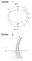
- a toric contact lens 1 has a prism ballast shape as a whole.
- the inner surface (back surface) 2 and the outer surface (front surface) 3 of the lens 1 are respectively formed of a spherical surface and a toric surface wherein the central axis B of the outer surface 3 is determined at a position lower than the central axis A of the inner surface 2, and the both central axis A, B extend in parallel. Accordingly, the thickness of the toric contact lens 1 increases downwardly whereby the gravity center is shifted downwardly ( Figure 2). Further, spherical cut surfaces 6, 7 (surfaces resulted by forming slab-off portions) are formed respectively in upper and lower slab-off portions 4, 5 of the toric contact lens 1.
- Numeral 8 designates the border line between the outer surface 3 and the cut surface 6
- numeral 9 designates the boarder line between the outer surface 3 and the cut surface 7.
- the region 10 surrounded by the border lines 8 and 9 provides an effective optical zone which actually performs function as a contact lens.
- the outer surface 3 is provided with a toric surface which comprises curved surfaces having different radius of curvatures in the directions of two orthogonally intersecting meridians.
- the toric surface corrects astigmatism. Accordingly, it is easy to form the toric surface by a lathe cutting process in comparison with the forming of it in the inner surface 2.
- the same effect of preventing the rotation as the ballast type is obtainable since the toric contact lens is formed to have a prism ballast shape as a whole whereby the gravity center is shifted downwardly. Further, since the upper and lower peripheral portions are shaved or cut, the deviation rate of the lens is smaller than that of the prism ballast type. Accordingly, the largest thickness of the toric contact lens 1 (the thickness of the lowermost portion of the toric lens 1 shown in Figure 2) can be reduced, and at the same time, the thickness in the entire portion of the toric contact lens 1 can be reduced, whereby the feeling of wearing can be improved. Further, an amount of oxygen to be supplied to the cornea can be increased to thereby prevent the cornea from injuring.
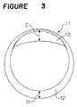
- Figure 3 shows another embodiment of the toric contact lens 11 according to the present invention.
- the lower slab-off portion extends to the upper portion through both side portions. Namely, a lower cut surface 12 is first formed and then, an upper cut surface 13 is formed.
- two-dotted chain line designates the boarder line of the lower cut surface 12 which disappears by the formation of the upper cut surface 13.
- the toric contact lens 11 performs the same function as the toric contact lens 1.
- FIG 4 shows a multifocal contact lens 20 for presbyopia as another embodiment of the present invention.
- the multifocal contact lens 20 has the same prism ballast and slab-off portions (the slab-off portions are indicated by cut surfaces 24) as the toric contact lens, shown in Figure 1.
- An optical zone is formed between the cut surfaces which are provided at upper and lower portions of the lens.
- the optical zone is constituted by a near vision correction zone to see near objects, a far vision correction zone to see distant objects and an intermediate distance correction zone 23 having an intermediate function of correction of those of the near vision correction zone 21 and the far vision correction zone 24, which is formed between those zones 21, 24.
- the near vision correction zone 21 and the intermediate distance correction zone 23 are shifted to the right side (the nose side) so as to be easy to watch near objects in a time of reading a book, for instance.
- Figure 5 shows a multifocal (bifocal) contact lens 25 for presbyopia as another embodiment of the present invention.
- the contact lens 25 has the same prism ballast and slab-off portions (the slab-off portions are indicated by cut surfaces 28, 29) as the toric contact lens 11 shown in Figure 3.
- Numeral 26 designates a near vision correction zone to see near objects formed at the front side of the contact lens 25
- numeral 27 designates a far vision correction zone to see distant objects.
- the contact lens 25 has the near vision correction zone 26 at its lower position so as to be capable of seeing near objects in a time of reading a book, for instance.
- areas having different degree of lens power are not at positions of rotation symmetry in the front view of the lens. They are of a type that it is necessary for a wearer to wear it at a fixed eye position, in the same manner as the toric contact lens.
- the deviation rate of the lens is preferably selected from the range of 2.5% - 7.5% because when the deviation rate exceeds 7.5%, the lens becomes thick by the requirement in the parameters, and on the other hand, when it is less than 2.5%, a sufficient effect of ballast can not be obtained. In order to effectively obtain stability on the rotation of the lens, it is preferable to select the deviation rate in a range of 3.5 - 5.5%.
- the ballast formed in the contact lens of the present invention is of the prism ballast type. Accordingly, the surface of the lens is very smooth unlike the conventional contact lens wherein the lower portion is simply weighed. Accordingly, the feeling of wearing is further improved.
- the deviation rate of the lens is first determined. Then, the deviation quantity of the lens (namely, the distance of the gravity center from the geometric center) is calculated so as to obtain the predetermined deviation rate of the lens. Then, the prism quantity of the lens and the width of slab-off portions are set. It is natural to consider the deviation quantity of the lens due to the toric or multifocal (bifocal) surface in the designing of the contact lens 1, 11, 20 or 25.
- a flowchart in Figure 4 shows preferred steps of the design for the toric contact lens.
- the smallest thickness t min of the toric contact lens 1 by which the necessary strength can be obtained is set.
- the smallest thickness t min varies depending on material used and is set in consideration of various conditions. Further, a desired deviation quantity H for the lens is also set.
- the radius of curvature of the inner surface 2, i.e. the base curve (BC) is set so as to meet the shape of the cornea of a wearer (Step 14).
- the outer surface 3 is so designed as to meet desired parameters of contact lens (e.g. the degree of spherical power, the degree of cylindrical power, the axis of correction for astigmatism and so on) in consideration of the previously set base curve (Step 15).
- desired parameters of contact lens e.g. the degree of spherical power, the degree of cylindrical power, the axis of correction for astigmatism and so on
- the prism quantity (the degree of prism diopter) is optionally set (Step 16).
- the thickness of the lens is measured (Step 17). Since the toric contact lens 1 is formed to have a prism ballast, the geometric center of the inner surface 2 does not coincide with that of the outer surface 3. Accordingly, since the position where the thickness of the lens is the smallest is a position other than the geometric center or the spherical portion of the contact lens, the smallest thickness of the lens is set by examining the thickness of the lens at various positions. As a result, when the smallest value in the thickness t of the lens indicates the smallest thickness portion t min , the next step is taken. Otherwise, the procedure is returned to Step 16 to set the prism quantity (the degree of prism) again.
- the width of the upper and lower slab-off portions is set (Step 18).
- the width of the upper slab-off portion (the width C in Figures 1 and 3) should be maintained to be greater as possible to thereby obtain a large deviation quantity, which can further improve the effect of preventing the rotation. Accordingly, a large value (e.g. 2.5 mm) should be previously set, however, the value may be an optional value.
- the position of gravity center (deviation quantity) is calculated (Step 19).
- the prism quantity the degree of prism diopter
- the width of the slab-off portions which have been obtained in the previous steps are set as formal values.
- the sequential step is returned to Step 18 where the width of the slab-off portions is set again.
- the width C of the upper slab-portion is 2.5 mm
- the width D of the lower slab-off portion ( Figure 1 and Figure 3) is limited to 0.1 mm - 2.5 mm so that the effective width of the optical portion 10 of the toric contact lens 1 can be assured.
- the sequential step is returned to Step 16 where the prism quantity (the degree of prism) is set again.
- the toric contact lens 1 having the smallest thickness is employed in consideration of the thickness at various positions (the thickness at the central portion, the peripheral portions and so on) of the lens.
- a lathe cutting process or a molding process which can render the manufacture easy may be used.
- the multifocal (bifocal) contact lens of the present invention can be designed in the same manner as the toric contact lens described above. Further, it can be manufactured by either process of lathe cutting or molding.
- the following advantages are obtainable.
- the rotation of the lens can be effectively prevented. Excellent feeling of wearing is obtainable. It is safe in use because a sufficient amount of oxygen to the cornea can be assured. Further, the flexibility of the design is obtainable because restriction to the parameter of the lens can be substantially expanded. Further, since the prism quantity (the degree of prism) can be smaller than the conventional technique, and an adverse optical effect such as polarization can be reduced.
Abstract
Description
- The present invention relates to a contact lens for correcting astigmatism or presbyopia. More particularly, it relates to a toric contact lens or a multifocal (bifocal) contact lens capable of preventing the rotation of it on the eye during use.
- The astigmatism is a state that parallel beams do not form an image at a point and the presbyopia is a state that a man becomes inability to attain a sharp focus for near vision due to the reduction of elasticity of the crystalline lens. In order to correct the astigmatism or presbyopia, glasses or a contact lens is usually used.
- As a contact lens to correct the astigmatism, there is known a toric contact lens wherein the radius of curvature of the inner (back) and/or the outer (front) surfaces is different from each other in terms of two orthogonally intersecting meridians.
- As a contact lens to correct the presbyopia, there is known a multifocal (bifocal) contact lens wherein a plurality of areas of the degree of lens power are formed at the inner (back) and/or outer (front) surfaces in order to see near and distant objects.
- For a patient of astigmatism, it is necessary to wear a toric contact lens at a correct position on a human eye.
- There are various kinds of multifocal contact lens to be worn by patients of presbyopia, some kinds of multifocal contact lens have to be worn at a fixed position to human eyes in the same manner as the toric contact lens. The multifocal contact lens of the above-mentioned kind is such that the areas of the different degrees of lens power formed in the contact lens are not at the positions of rotation symmetry when the lens is viewed from the front side. When glasses are used, a frame holding lenses is fitted to the ears or the nose. Accordingly, the correct position of the lenses can be assured. However, when a toric contact lens or a certain kind of multifocal contact lens is used, there is no means to fix the lenses, and accordingly, the contact lenses tend to rotate on the eye, whereby it may not obtain proper correction.
- For the toric contact lens or the multifocal contact lens, there have been proposed various improvements to prevent the rotation of the lens on the eye. The proposed improvements can be generally classified into two types.
- The first type is called a ballast type wherein the lower portion of the contact lens is relatively made heavy to thereby prevent the rotation of the lens on the eye (the cornea). A bifocal (multifocal) type contact lens 31 (Figure 5) which belongs this type, has bee known (for instance, in Japanese Examined Patent Publication No. 18531/1962).
- The second type is such one as to correspond to the shape of the eye of a wearer so that the rotation of the lens on the cornea can be prevented. The second type can also be classified into two types: a truncation type and a slab-off type. In the truncation type, a cut portion (a truncated portion) 33 is formed at a part of the outer periphery of a contact lens (Figure 6), which is disclosed in, for instance, Japanese Unexamined Utility Model Publication No. 13048/1973). In the slab-off type, a
thin portion 35 is formed in a contact lens 34 (Figure 7) which is disclosed in, for instance, Japanese Unexamined Utility Model Publication No. 133151/1975. - In the ballast type contact lens, the thickness in a portion of the lens is increased to shift the gravity center to the lower portion. Therefore, the ballast type contact lens has a disadvantage that a wearer may feel a pressure on the eye, discomfort or pain. In order to improve the discomfort, a so-called prism ballast type contact lens is proposed wherein the central axis of the outer surface of the contact lens is deviated from the central axis of the inner surface so that the thickness of the lens is gradually increased downwardly. The proposed prism ballast type contact lens has, however, such a disadvantage that when a lens is designed in accordance with the parameters (such as the degree of lens power), there may result a thicker portion in the lens, to which a wearer can not endure. Further, as the thickness of the lens is increased, an amount of oxygen to be transmitted therethrough is reduced, whereby the cornea may be injured.
- On the other hand, since the truncation type contact lens is so formed that the peripheral region of the lens in a plane view is not smooth, a wearer may feel discomfort when the lens is worn. In order to improve the feeling of wearing, it is necessary to finish the truncated portion smoothly. However, it requires high skill and technique. Further, even though a truncated portion having a smooth surface is formed, sufficient effect can not be expected depending on the shape of eyelid of a wearer.
- In the slab-off type contact lens, there is no problem on the feeling of wearing. However, the contact lens has its gravity center which coincides with geometric center. Accordingly, there is a problem of stability because the lens may rotate on the cornea when the eye blinks.
- In order to solve the problems of the ballast type, the truncation type and the slab-off type contact lens as described above, a technique in combination of the ballast type and the slab-off type has been proposed as follows.
- Firstly, in U.S.P. 4,324,461, a thin wall portion (hereinbelow, referred to as a slab-off portion) is formed at the upper portion of a lens to shift the gravity center downwardly.
- Secondly, in U.S.P. 5,020,898, slab-off portions are formed at the upper and lower portions of a lens to thereby shift the gravity center downwardly. In these proposals, however, it is difficult to assure a proper deviation of the gravity center necessary for preventing the rotation of the lens on the cornea. Further, excellent and stable eyesight may not be obtained.
- There is another proposal wherein a slab-off portion is formed in the lower portion of the lens and a prism is formed in the lens to make the lower portion of the lens heavy (U.S.P. 4,508,436 and U.S.P. 4,573,774). In the proposal, however, the position of the gravity center is moved upwardly since the slab-off portion is formed in the lower portion of the lens, whereby there is little effect to prevent the rotation of the lens on the eye.
- It is an object of the present invention to eliminate the problems of the above-mentioned techniques and to provide a thin toric or multifocal (bifocal) contact lens for certainly preventing the rotation on the cornea, providing comfort feeling and assuring safe use.
- Conventionally, a prism ballast type contact lens, which is for stabilizing the rotation of the lens by forming a prism ballast, has been so designed and developed as to how much amount of prism is formed, i.e., depending on a quantity of prism (a degree of prism diopter). The inventors of the application have completed the present invention from a new viewpoint. Namely, they have considered that how much amount of a deviation rate or an offset is resulted by the employment of a prism ballast, and have designed and developed the lens so that a suitable effect of ballast can be obtained by making the lens thin as possible.
- The deviation rate or the offset means the percentage of the distance (deviation quantity) between the geometric center of the lens in the front view of the lens and the gravity center. Namely, when the gravity center of the contact lens having a total diameter of 14 mm is offset by 0.6 mm from the geometric center, the deviation rate is 0.6 ÷ 14 × 100 = 4.3 (%). In this case, the deviation quantity is 0.6 mm. As a result, the inventors have found that sufficient stability to the rotation of the lens can be obtained by determining the deviation rate from the geometric center of the lens in a range from 2.5% to 7.5% which is applicable to the parameters for all toric contact lenses.
- In accordance with the present invention, there is provided a toric or multifocal (bifocal) contact lens having a prism ballast shape and the gravity center deviated downwardly from its geometric center, characterized in that thinner wall regions are formed in at least upper and lower peripheral portions of the lens.
- In the present invention, the toric or multifocal (bifocal) contact lens preferably has the deviation rate of the gravity center from the geometric center in a range from 2.5% to 7.5%.
- In drawings:
- Figure 1 is a front view showing a first embodiment of the toric contact lens according to the present invention;
- Figure 2 is a cross-sectional view taken along a line II-II of the toric contact lens in Figure 1;
- Figure 3 is a front view showing another embodiment of the toric contact lens according to the present invention;
- Figure 4 is a front view showing another embodiment on the multifocal (bifocal) contact lens according to the present invention;
- Figure 5 is a front view showing a still another embodiment of the multifocal (bifocal) contact lens according to the present invention;
- Figure 6 is a flowchart showing steps of designing the toric contact lens of the present invention;
- Figure 7 is a cross-sectional view of a conventional contact lens;
- Figure 8 is a front view showing another conventional contact lens; and
- Figure 9 is a cross-sectional view showing another conventional contact lens.
- Preferred embodiments of the contact lens according to the present invention will be described with reference to the drawings.
- As shown in Figures 1 and 2, a toric contact lens 1 has a prism ballast shape as a whole. Namely, the inner surface (back surface) 2 and the outer surface (front surface) 3 of the lens 1 are respectively formed of a spherical surface and a toric surface wherein the central axis B of the
outer surface 3 is determined at a position lower than the central axis A of theinner surface 2, and the both central axis A, B extend in parallel. Accordingly, the thickness of the toric contact lens 1 increases downwardly whereby the gravity center is shifted downwardly (Figure 2). Further, spherical cut surfaces 6, 7 (surfaces resulted by forming slab-off portions) are formed respectively in upper and lower slab-offportions outer surface 3 and thecut surface 6, and numeral 9 designates the boarder line between theouter surface 3 and the cut surface 7. Theregion 10 surrounded by theborder lines 8 and 9 provides an effective optical zone which actually performs function as a contact lens. - The
outer surface 3 is provided with a toric surface which comprises curved surfaces having different radius of curvatures in the directions of two orthogonally intersecting meridians. The toric surface corrects astigmatism. Accordingly, it is easy to form the toric surface by a lathe cutting process in comparison with the forming of it in theinner surface 2. - In the toric contact lens having the above-mentioned construction, the same effect of preventing the rotation as the ballast type is obtainable since the toric contact lens is formed to have a prism ballast shape as a whole whereby the gravity center is shifted downwardly. Further, since the upper and lower peripheral portions are shaved or cut, the deviation rate of the lens is smaller than that of the prism ballast type. Accordingly, the largest thickness of the toric contact lens 1 (the thickness of the lowermost portion of the toric lens 1 shown in Figure 2) can be reduced, and at the same time, the thickness in the entire portion of the toric contact lens 1 can be reduced, whereby the feeling of wearing can be improved. Further, an amount of oxygen to be supplied to the cornea can be increased to thereby prevent the cornea from injuring.
- Figure 3 shows another embodiment of the
toric contact lens 11 according to the present invention. In this embodiment, the lower slab-off portion extends to the upper portion through both side portions. Namely, alower cut surface 12 is first formed and then, anupper cut surface 13 is formed. In Figure 3, two-dotted chain line designates the boarder line of thelower cut surface 12 which disappears by the formation of theupper cut surface 13. Thetoric contact lens 11 performs the same function as the toric contact lens 1. - Figure 4 shows a
multifocal contact lens 20 for presbyopia as another embodiment of the present invention. Themultifocal contact lens 20 has the same prism ballast and slab-off portions (the slab-off portions are indicated by cut surfaces 24) as the toric contact lens, shown in Figure 1. An optical zone is formed between the cut surfaces which are provided at upper and lower portions of the lens. The optical zone is constituted by a near vision correction zone to see near objects, a far vision correction zone to see distant objects and an intermediatedistance correction zone 23 having an intermediate function of correction of those of the nearvision correction zone 21 and the farvision correction zone 24, which is formed between thosezones contact lens 20, the nearvision correction zone 21 and the intermediatedistance correction zone 23 are shifted to the right side (the nose side) so as to be easy to watch near objects in a time of reading a book, for instance. - Figure 5 shows a multifocal (bifocal)
contact lens 25 for presbyopia as another embodiment of the present invention. In this embodiment, thecontact lens 25 has the same prism ballast and slab-off portions (the slab-off portions are indicated by cut surfaces 28, 29) as thetoric contact lens 11 shown in Figure 3.Numeral 26 designates a near vision correction zone to see near objects formed at the front side of thecontact lens 25, and numeral 27 designates a far vision correction zone to see distant objects. As is clear from Figure 5, thecontact lens 25 has the nearvision correction zone 26 at its lower position so as to be capable of seeing near objects in a time of reading a book, for instance. - In either of the multifocal (bifocal) contact lenses shown in Figure 4 and 5, areas having different degree of lens power are not at positions of rotation symmetry in the front view of the lens. They are of a type that it is necessary for a wearer to wear it at a fixed eye position, in the same manner as the toric contact lens.
- The deviation rate of the lens is preferably selected from the range of 2.5% - 7.5% because when the deviation rate exceeds 7.5%, the lens becomes thick by the requirement in the parameters, and on the other hand, when it is less than 2.5%, a sufficient effect of ballast can not be obtained. In order to effectively obtain stability on the rotation of the lens, it is preferable to select the deviation rate in a range of 3.5 - 5.5%.
- The ballast formed in the contact lens of the present invention is of the prism ballast type. Accordingly, the surface of the lens is very smooth unlike the conventional contact lens wherein the lower portion is simply weighed. Accordingly, the feeling of wearing is further improved.
- In designing the
contact lens contact lens - A flowchart in Figure 4 shows preferred steps of the design for the toric contact lens.
- First, the smallest thickness tmin of the toric contact lens 1 by which the necessary strength can be obtained is set. The smallest thickness tmin varies depending on material used and is set in consideration of various conditions. Further, a desired deviation quantity H for the lens is also set.
- Then, the radius of curvature of the
inner surface 2, i.e. the base curve (BC) is set so as to meet the shape of the cornea of a wearer (Step 14). - In the following, the
outer surface 3 is so designed as to meet desired parameters of contact lens (e.g. the degree of spherical power, the degree of cylindrical power, the axis of correction for astigmatism and so on) in consideration of the previously set base curve (Step 15). - Then, the prism quantity (the degree of prism diopter) is optionally set (Step 16).
- Then, the thickness of the lens is measured (Step 17). Since the toric contact lens 1 is formed to have a prism ballast, the geometric center of the
inner surface 2 does not coincide with that of theouter surface 3. Accordingly, since the position where the thickness of the lens is the smallest is a position other than the geometric center or the spherical portion of the contact lens, the smallest thickness of the lens is set by examining the thickness of the lens at various positions. As a result, when the smallest value in the thickness t of the lens indicates the smallest thickness portion tmin, the next step is taken. Otherwise, the procedure is returned toStep 16 to set the prism quantity (the degree of prism) again. - Then, the width of the upper and lower slab-off portions is set (Step 18). In the setting, the width of the upper slab-off portion (the width C in Figures 1 and 3) should be maintained to be greater as possible to thereby obtain a large deviation quantity, which can further improve the effect of preventing the rotation. Accordingly, a large value (e.g. 2.5 mm) should be previously set, however, the value may be an optional value.
- Then, the position of gravity center (deviation quantity) is calculated (Step 19). In the calculation, when the deviation quantity assumes a deviation quantity H, which has been initially set, or higher, the prism quantity (the degree of prism diopter) and the width of the slab-off portions which have been obtained in the previous steps are set as formal values. When the deviation quantity is less than H, the sequential step is returned to
Step 18 where the width of the slab-off portions is set again. In this case, when the width C of the upper slab-portion is 2.5 mm, the width D of the lower slab-off portion (Figure 1 and Figure 3) is limited to 0.1 mm - 2.5 mm so that the effective width of theoptical portion 10 of the toric contact lens 1 can be assured. - In case that a desired deviation quantity can not be obtained even by the operation at
Step 18, the sequential step is returned toStep 16 where the prism quantity (the degree of prism) is set again. - When there is scattering in dimension of the toric contact lens designed by the above-mentioned steps and by using the same parameter, the toric contact lens 1 having the smallest thickness is employed in consideration of the thickness at various positions (the thickness at the central portion, the peripheral portions and so on) of the lens.
- In manufacturing the toric contact lens 1 designed by the above-mentioned steps, a lathe cutting process or a molding process which can render the manufacture easy may be used.
- The multifocal (bifocal) contact lens of the present invention can be designed in the same manner as the toric contact lens described above. Further, it can be manufactured by either process of lathe cutting or molding.
- In the embodiments described above, description has been made as to the contact lens in which the toric or multifocal (bifocal) surface is formed in the outer surface. However, the present invention is not limited to the embodiments, and a toric or multifocal (bifocal) surface may be formed in the inner surface or both surfaces.
- According to the toric or multifocal (bifocal) contact lens of the present invention, the following advantages are obtainable. The rotation of the lens can be effectively prevented. Excellent feeling of wearing is obtainable. It is safe in use because a sufficient amount of oxygen to the cornea can be assured. Further, the flexibility of the design is obtainable because restriction to the parameter of the lens can be substantially expanded. Further, since the prism quantity (the degree of prism) can be smaller than the conventional technique, and an adverse optical effect such as polarization can be reduced.
Claims (2)
- A contact lens for preventing the rotation on an eye in use which has a prism ballast shape and the gravity center deviated downwardly from its geometric center, characterized in that thinner wall regions are formed in at least upper and lower peripheral portions of the lens.
- The contact lens according to Claim 1, wherein the deviation rate of the gravity center of the lens from its geometric center is in a range from 2.5% to 7.5%.
Priority Applications (7)
| Application Number | Priority Date | Filing Date | Title |
|---|---|---|---|
| US08/130,728 US5532768A (en) | 1993-10-04 | 1993-10-04 | Contact lens |
| DE1993624144 DE69324144T2 (en) | 1993-10-05 | 1993-10-05 | Contact lens |
| EP98116593A EP0883014B1 (en) | 1993-10-05 | 1993-10-05 | Contact lens |
| EP93116083A EP0646825B1 (en) | 1993-10-04 | 1993-10-05 | Contact lens |
| ES93116083T ES2130201T3 (en) | 1993-10-05 | 1993-10-05 | CONTACT LENS. |
| ES98116593T ES2190559T3 (en) | 1993-10-05 | 1993-10-05 | CONTACT LENS. |
| DE1993632627 DE69332627T2 (en) | 1993-10-05 | 1993-10-05 | contact lens |
Applications Claiming Priority (2)
| Application Number | Priority Date | Filing Date | Title |
|---|---|---|---|
| US08/130,728 US5532768A (en) | 1993-10-04 | 1993-10-04 | Contact lens |
| EP93116083A EP0646825B1 (en) | 1993-10-04 | 1993-10-05 | Contact lens |
Related Child Applications (1)
| Application Number | Title | Priority Date | Filing Date |
|---|---|---|---|
| EP98116593A Division EP0883014B1 (en) | 1993-10-05 | 1993-10-05 | Contact lens |
Publications (2)
| Publication Number | Publication Date |
|---|---|
| EP0646825A1 true EP0646825A1 (en) | 1995-04-05 |
| EP0646825B1 EP0646825B1 (en) | 1999-03-24 |
Family
ID=26133454
Family Applications (1)
| Application Number | Title | Priority Date | Filing Date |
|---|---|---|---|
| EP93116083A Expired - Lifetime EP0646825B1 (en) | 1993-10-04 | 1993-10-05 | Contact lens |
Country Status (2)
| Country | Link |
|---|---|
| US (1) | US5532768A (en) |
| EP (1) | EP0646825B1 (en) |
Cited By (6)
| Publication number | Priority date | Publication date | Assignee | Title |
|---|---|---|---|---|
| EP0942311A1 (en) * | 1998-03-09 | 1999-09-15 | Menicon Co., Ltd. | Prism ballast type contact lens, method of producing the same, and mold assembly used in producing the lens |
| EP0949529A2 (en) * | 1998-04-10 | 1999-10-13 | Menicon Co., Ltd. | Toric multifocal lens having different astigmatism corrective optical powers in respective vision correction regions, and method of producing the same |
| EP0982618A1 (en) * | 1998-08-26 | 2000-03-01 | Menicon Co., Ltd. | Presbyopia correction contact lens |
| EP1008890A1 (en) * | 1998-12-09 | 2000-06-14 | JOHNSON & JOHNSON VISION PRODUCTS, INC. | Toric contact lenses |
| EP1014156A1 (en) * | 1998-12-21 | 2000-06-28 | JOHNSON & JOHNSON VISION PRODUCTS, INC. | Contact lenses with constant peripheral geometry |
| EP2318880A1 (en) * | 2008-08-28 | 2011-05-11 | Johnson & Johnson Vision Care, Inc. | Toric contact lenses |
Families Citing this family (24)
| Publication number | Priority date | Publication date | Assignee | Title |
|---|---|---|---|---|
| US5980040A (en) * | 1997-06-30 | 1999-11-09 | Wesley Jessen Corporation | Pinhole lens and contact lens |
| AU5545699A (en) | 1998-08-06 | 2000-02-28 | John B. W. Lett | Multifocal aspheric lens |
| US6286956B1 (en) * | 1998-10-19 | 2001-09-11 | Mencion Co., Ltd. | Multifocal ocular lens including intermediate vision correction region between near and distant vision correction regions |
| AU2365300A (en) | 1998-12-16 | 2000-07-03 | Wesley-Jessen Corporation | Multifocal contact lens with aspheric surface |
| CN100510847C (en) * | 2000-03-31 | 2009-07-08 | 库柏维景国际控股公司 | Contact lens |
| US7628485B2 (en) * | 2000-03-31 | 2009-12-08 | Coopervision International Holding Company, Lp | Contact lens having a uniform horizontal thickness profile |
| US6467903B1 (en) | 2000-03-31 | 2002-10-22 | Ocular Sciences, Inc. | Contact lens having a uniform horizontal thickness profile |
| EP1783534A3 (en) * | 2000-03-31 | 2011-05-11 | Coopervision International Holding Company, LP. | Contact lens having a uniform horizontal thickness profile |
| US7152975B2 (en) * | 2000-11-10 | 2006-12-26 | Cooper Vision, Inc. | Junctionless ophthalmic lenses and methods for making same |
| US6923540B2 (en) * | 2002-07-31 | 2005-08-02 | Novartis Ag | Toric multifocal contact lenses |
| JP4485360B2 (en) * | 2002-08-06 | 2010-06-23 | ノバルティス アーゲー | contact lens |
| WO2004104675A2 (en) * | 2003-05-21 | 2004-12-02 | Novartis Ag | Contact lenses |
| US6939005B2 (en) | 2003-08-20 | 2005-09-06 | Johnson & Johnson Vision Care Inc. | Rotationally stabilized contact lenses |
| AU2003275683A1 (en) * | 2003-10-27 | 2005-05-11 | Menicon Co., Ltd. | Contact lens |
| US7036930B2 (en) | 2003-10-27 | 2006-05-02 | Johnson & Johnson Vision Care, Inc. | Methods for reducing corneal staining in contact lens wearers |
| US6988800B2 (en) * | 2004-01-06 | 2006-01-24 | St. Shine Optical Co., Ltd. | Toric contact lens with meniscus-shaped flattened top and bottom zones for dynamic stabilization |
| US7201480B2 (en) * | 2004-05-20 | 2007-04-10 | Johnson & Johnson Vision Care, Inc. | Methods for rotationally stabilizing contact lenses |
| AR062067A1 (en) * | 2006-07-17 | 2008-10-15 | Novartis Ag | TORICAS CONTACT LENSES WITH CONTROLLED OPTICAL POWER PROFILE |
| US8646908B2 (en) * | 2008-03-04 | 2014-02-11 | Johnson & Johnson Vision Care, Inc. | Rotationally stabilized contact lenses and methods for their design |
| CN103782225B (en) * | 2011-09-09 | 2017-09-15 | 伊齐基尔私人有限公司 | The method of casting molding parallel-moving type multifocal contact lens |
| IL303151A (en) | 2015-09-23 | 2023-07-01 | Ohio State Innovation Foundation | Contact lens comprising a lenticular in a superior portion of the contact lens |
| US10191302B2 (en) | 2015-09-23 | 2019-01-29 | Ohio State Innovation Foundation | Contact lens comprising lenticular-like curve |
| US11320673B2 (en) | 2017-09-01 | 2022-05-03 | Ohio State Innovation Foundation | Soft contact lens comprising a lenticular in a superior portion of the contact lens with enhanced tear exchange |
| CN114127621A (en) * | 2019-05-20 | 2022-03-01 | 梁俊忠 | Wavefront treatment method and device for astigmatism, coma and presbyopia of human eyes |
Citations (8)
| Publication number | Priority date | Publication date | Assignee | Title |
|---|---|---|---|---|
| EP0008726A1 (en) * | 1978-09-04 | 1980-03-19 | Hirst Contact Lens Limited | Contact lenses and methods of making the same |
| GB2041557A (en) * | 1978-10-05 | 1980-09-10 | Kwok Chu Fung J | Soft contact lenses |
| DE3003985A1 (en) * | 1980-02-04 | 1981-08-13 | Hecht Contactlinsen GmbH, 7800 Freiburg | CONTACTLINSE |
| EP0062178A1 (en) * | 1981-03-23 | 1982-10-13 | BAUSCH & LOMB INCORPORATED | Stabilizing carrier for toric contact lenses |
| EP0102223A2 (en) * | 1982-08-19 | 1984-03-07 | Vistakon, Inc. | Bifocal soft contact lens |
| US4573774A (en) * | 1981-09-28 | 1986-03-04 | Vistakon, Inc. | Soft toric contact lens |
| US4618229A (en) * | 1983-07-22 | 1986-10-21 | Bausch & Lomb Incorporated | Bifocal contact lens |
| EP0452549A1 (en) * | 1990-04-19 | 1991-10-23 | HEINRICH WÖHLK, INSTITUT FÜR CONTACTLINSEN GmbH & CO. | Contact lens with position stabilisation |
Family Cites Families (9)
| Publication number | Priority date | Publication date | Assignee | Title |
|---|---|---|---|---|
| DE2413845C3 (en) * | 1974-03-22 | 1979-08-02 | Moeller & Neumann Gmbh, 6670 St Ingbert | Accumulation roller table for rolled bars, in particular flat or profile bars, with subsequent transverse conveyance |
| US4095878A (en) * | 1974-03-28 | 1978-06-20 | Titmus Eurocon Kontaktlinsen Gmbh & Co. Kg | Soft contact lens with flattened region for automatic orientation |
| US4324461A (en) * | 1979-11-26 | 1982-04-13 | Salvatori Ophthalmics, Inc. | Contact lens for non-rotational orientation |
| US4508436A (en) * | 1981-09-28 | 1985-04-02 | Frontier Contact Lenses Of Florida, Inc. | Soft toric contact lens |
| DE3222099C2 (en) * | 1982-06-11 | 1984-06-20 | Titmus Eurocon Kontaktlinsen Gmbh & Co Kg, 8750 Aschaffenburg | Bifocal contact lens of the bivisual type |
| US4628229A (en) * | 1983-02-15 | 1986-12-09 | Olympus Optical Company, Ltd | Flashlight emission apparatus |
| CA1265688A (en) * | 1984-10-17 | 1990-02-13 | Alain Rainville | Bi-focal corneal lens and method of making the same |
| US5076683A (en) * | 1988-09-14 | 1991-12-31 | Allergan, Inc. | Spuncast compound contact lens |
| US5020898A (en) * | 1990-01-29 | 1991-06-04 | Schering Corporation | Contact lens for correction of astigmatism |
-
1993
- 1993-10-04 US US08/130,728 patent/US5532768A/en not_active Expired - Lifetime
- 1993-10-05 EP EP93116083A patent/EP0646825B1/en not_active Expired - Lifetime
Patent Citations (8)
| Publication number | Priority date | Publication date | Assignee | Title |
|---|---|---|---|---|
| EP0008726A1 (en) * | 1978-09-04 | 1980-03-19 | Hirst Contact Lens Limited | Contact lenses and methods of making the same |
| GB2041557A (en) * | 1978-10-05 | 1980-09-10 | Kwok Chu Fung J | Soft contact lenses |
| DE3003985A1 (en) * | 1980-02-04 | 1981-08-13 | Hecht Contactlinsen GmbH, 7800 Freiburg | CONTACTLINSE |
| EP0062178A1 (en) * | 1981-03-23 | 1982-10-13 | BAUSCH & LOMB INCORPORATED | Stabilizing carrier for toric contact lenses |
| US4573774A (en) * | 1981-09-28 | 1986-03-04 | Vistakon, Inc. | Soft toric contact lens |
| EP0102223A2 (en) * | 1982-08-19 | 1984-03-07 | Vistakon, Inc. | Bifocal soft contact lens |
| US4618229A (en) * | 1983-07-22 | 1986-10-21 | Bausch & Lomb Incorporated | Bifocal contact lens |
| EP0452549A1 (en) * | 1990-04-19 | 1991-10-23 | HEINRICH WÖHLK, INSTITUT FÜR CONTACTLINSEN GmbH & CO. | Contact lens with position stabilisation |
Cited By (12)
| Publication number | Priority date | Publication date | Assignee | Title |
|---|---|---|---|---|
| EP0942311A1 (en) * | 1998-03-09 | 1999-09-15 | Menicon Co., Ltd. | Prism ballast type contact lens, method of producing the same, and mold assembly used in producing the lens |
| US6158861A (en) * | 1998-03-09 | 2000-12-12 | Menicon Co., Ltd. | Prism ballast type contact lens, method of producing the same, and mold assembly used in producing the lens |
| EP0949529A2 (en) * | 1998-04-10 | 1999-10-13 | Menicon Co., Ltd. | Toric multifocal lens having different astigmatism corrective optical powers in respective vision correction regions, and method of producing the same |
| EP0949529A3 (en) * | 1998-04-10 | 2000-01-12 | Menicon Co., Ltd. | Toric multifocal lens having different astigmatism corrective optical powers in respective vision correction regions, and method of producing the same |
| US6142625A (en) * | 1998-04-10 | 2000-11-07 | Menicon Co., Ltd. | Toric multifocal lens having different astigmatism corrective optical powers in respective vision correction regions, and method of producing the same |
| EP0982618A1 (en) * | 1998-08-26 | 2000-03-01 | Menicon Co., Ltd. | Presbyopia correction contact lens |
| US6199982B1 (en) | 1998-08-26 | 2001-03-13 | Menicon Co., Ltd. | Presbyopia correction contact lens |
| EP1008890A1 (en) * | 1998-12-09 | 2000-06-14 | JOHNSON & JOHNSON VISION PRODUCTS, INC. | Toric contact lenses |
| US6176578B1 (en) | 1998-12-09 | 2001-01-23 | Johnson & Johnson Vision Care, Inc. | Toric contact lenses |
| EP1014156A1 (en) * | 1998-12-21 | 2000-06-28 | JOHNSON & JOHNSON VISION PRODUCTS, INC. | Contact lenses with constant peripheral geometry |
| US6183082B1 (en) | 1998-12-21 | 2001-02-06 | Johnson & Johnson Vision Care, Inc. | Contact lenses with constant peripheral geometry |
| EP2318880A1 (en) * | 2008-08-28 | 2011-05-11 | Johnson & Johnson Vision Care, Inc. | Toric contact lenses |
Also Published As
| Publication number | Publication date |
|---|---|
| US5532768A (en) | 1996-07-02 |
| EP0646825B1 (en) | 1999-03-24 |
Similar Documents
| Publication | Publication Date | Title |
|---|---|---|
| EP0646825B1 (en) | Contact lens | |
| US5020898A (en) | Contact lens for correction of astigmatism | |
| US6773107B2 (en) | Soft translating contact lens for presbyopia | |
| US4898461A (en) | Multifocal ophthalmic lens | |
| US5877839A (en) | Multifocal ophthalmic lens | |
| US4762408A (en) | Progressive multifocal lens and spectacles using same | |
| EP0102223B1 (en) | Bifocal soft contact lens | |
| AU605332B2 (en) | Multifocal ophthalmic lens | |
| US5166711A (en) | Multifocal ophthalmic lens | |
| CA2233062C (en) | Contact lens and process for fitting | |
| US4549794A (en) | Hydrophilic bifocal contact lens | |
| JPH04225314A (en) | Gas transmitting hard contact lens and manufacture thereof | |
| US20030016331A1 (en) | Bifocal contact lens with secondary prism | |
| EP1242845B1 (en) | Soft multifocal contact lens | |
| JP2000517438A (en) | Multifocal corneal contact lens | |
| CN117631322A (en) | Contact lens | |
| GB2041557A (en) | Soft contact lenses | |
| GB2031178A (en) | Contact lens | |
| JP2958189B2 (en) | Toric contact lens, method of manufacturing the lens, and method of designing the lens | |
| EP0883014B1 (en) | Contact lens | |
| EP1476783A1 (en) | Contact lenses with off-center sphere surface | |
| CA2096706A1 (en) | Soft toric lens for correction of astigmatism | |
| WO1998052090A1 (en) | Improved contact lens | |
| CA1244687A (en) | Contact lens |
Legal Events
| Date | Code | Title | Description |
|---|---|---|---|
| PUAI | Public reference made under article 153(3) epc to a published international application that has entered the european phase |
Free format text: ORIGINAL CODE: 0009012 |
|
| AK | Designated contracting states |
Kind code of ref document: A1 Designated state(s): DE ES FR GB |
|
| 17P | Request for examination filed |
Effective date: 19950828 |
|
| 17Q | First examination report despatched |
Effective date: 19970514 |
|
| GRAG | Despatch of communication of intention to grant |
Free format text: ORIGINAL CODE: EPIDOS AGRA |
|
| GRAG | Despatch of communication of intention to grant |
Free format text: ORIGINAL CODE: EPIDOS AGRA |
|
| GRAH | Despatch of communication of intention to grant a patent |
Free format text: ORIGINAL CODE: EPIDOS IGRA |
|
| GRAH | Despatch of communication of intention to grant a patent |
Free format text: ORIGINAL CODE: EPIDOS IGRA |
|
| GRAA | (expected) grant |
Free format text: ORIGINAL CODE: 0009210 |
|
| AK | Designated contracting states |
Kind code of ref document: B1 Designated state(s): DE ES FR GB |
|
| REF | Corresponds to: |
Ref document number: 69324144 Country of ref document: DE Date of ref document: 19990429 |
|
| REG | Reference to a national code |
Ref country code: ES Ref legal event code: FG2A Ref document number: 2130201 Country of ref document: ES Kind code of ref document: T3 |
|
| ET | Fr: translation filed | ||
| PLBE | No opposition filed within time limit |
Free format text: ORIGINAL CODE: 0009261 |
|
| STAA | Information on the status of an ep patent application or granted ep patent |
Free format text: STATUS: NO OPPOSITION FILED WITHIN TIME LIMIT |
|
| 26N | No opposition filed | ||
| REG | Reference to a national code |
Ref country code: GB Ref legal event code: IF02 |
|
| PGFP | Annual fee paid to national office [announced via postgrant information from national office to epo] |
Ref country code: GB Payment date: 20100929 Year of fee payment: 18 |
|
| PGFP | Annual fee paid to national office [announced via postgrant information from national office to epo] |
Ref country code: DE Payment date: 20100929 Year of fee payment: 18 |
|
| PGFP | Annual fee paid to national office [announced via postgrant information from national office to epo] |
Ref country code: FR Payment date: 20111103 Year of fee payment: 19 Ref country code: ES Payment date: 20111115 Year of fee payment: 19 |
|
| GBPC | Gb: european patent ceased through non-payment of renewal fee |
Effective date: 20121005 |
|
| REG | Reference to a national code |
Ref country code: FR Ref legal event code: ST Effective date: 20130628 |
|
| PG25 | Lapsed in a contracting state [announced via postgrant information from national office to epo] |
Ref country code: GB Free format text: LAPSE BECAUSE OF NON-PAYMENT OF DUE FEES Effective date: 20121005 Ref country code: DE Free format text: LAPSE BECAUSE OF NON-PAYMENT OF DUE FEES Effective date: 20130501 |
|
| REG | Reference to a national code |
Ref country code: DE Ref legal event code: R119 Ref document number: 69324144 Country of ref document: DE Effective date: 20130501 |
|
| PG25 | Lapsed in a contracting state [announced via postgrant information from national office to epo] |
Ref country code: FR Free format text: LAPSE BECAUSE OF NON-PAYMENT OF DUE FEES Effective date: 20121031 |
|
| REG | Reference to a national code |
Ref country code: ES Ref legal event code: FD2A Effective date: 20140116 |
|
| PG25 | Lapsed in a contracting state [announced via postgrant information from national office to epo] |
Ref country code: ES Free format text: LAPSE BECAUSE OF NON-PAYMENT OF DUE FEES Effective date: 20121006 |