EP0646874A1 - Multi-channel common-pool distributed data storage and retrieval system - Google Patents
Multi-channel common-pool distributed data storage and retrieval system Download PDFInfo
- Publication number
- EP0646874A1 EP0646874A1 EP94202712A EP94202712A EP0646874A1 EP 0646874 A1 EP0646874 A1 EP 0646874A1 EP 94202712 A EP94202712 A EP 94202712A EP 94202712 A EP94202712 A EP 94202712A EP 0646874 A1 EP0646874 A1 EP 0646874A1
- Authority
- EP
- European Patent Office
- Prior art keywords
- access
- data
- input
- channels
- storage
- Prior art date
- Legal status (The legal status is an assumption and is not a legal conclusion. Google has not performed a legal analysis and makes no representation as to the accuracy of the status listed.)
- Granted
Links
Images


Classifications
-
- G—PHYSICS
- G06—COMPUTING; CALCULATING OR COUNTING
- G06F—ELECTRIC DIGITAL DATA PROCESSING
- G06F3/00—Input arrangements for transferring data to be processed into a form capable of being handled by the computer; Output arrangements for transferring data from processing unit to output unit, e.g. interface arrangements
- G06F3/06—Digital input from, or digital output to, record carriers, e.g. RAID, emulated record carriers or networked record carriers
- G06F3/0601—Interfaces specially adapted for storage systems
-
- G—PHYSICS
- G06—COMPUTING; CALCULATING OR COUNTING
- G06F—ELECTRIC DIGITAL DATA PROCESSING
- G06F13/00—Interconnection of, or transfer of information or other signals between, memories, input/output devices or central processing units
- G06F13/38—Information transfer, e.g. on bus
- G06F13/40—Bus structure
- G06F13/4004—Coupling between buses
- G06F13/4022—Coupling between buses using switching circuits, e.g. switching matrix, connection or expansion network
-
- G—PHYSICS
- G11—INFORMATION STORAGE
- G11B—INFORMATION STORAGE BASED ON RELATIVE MOVEMENT BETWEEN RECORD CARRIER AND TRANSDUCER
- G11B27/00—Editing; Indexing; Addressing; Timing or synchronising; Monitoring; Measuring tape travel
- G11B27/002—Programmed access in sequence to a plurality of record carriers or indexed parts, e.g. tracks, thereof, e.g. for editing
-
- H—ELECTRICITY
- H04—ELECTRIC COMMUNICATION TECHNIQUE
- H04N—PICTORIAL COMMUNICATION, e.g. TELEVISION
- H04N7/00—Television systems
- H04N7/16—Analogue secrecy systems; Analogue subscription systems
- H04N7/173—Analogue secrecy systems; Analogue subscription systems with two-way working, e.g. subscriber sending a programme selection signal
- H04N7/17309—Transmission or handling of upstream communications
- H04N7/17318—Direct or substantially direct transmission and handling of requests
-
- G—PHYSICS
- G06—COMPUTING; CALCULATING OR COUNTING
- G06F—ELECTRIC DIGITAL DATA PROCESSING
- G06F3/00—Input arrangements for transferring data to be processed into a form capable of being handled by the computer; Output arrangements for transferring data from processing unit to output unit, e.g. interface arrangements
- G06F3/06—Digital input from, or digital output to, record carriers, e.g. RAID, emulated record carriers or networked record carriers
- G06F2003/0697—Digital input from, or digital output to, record carriers, e.g. RAID, emulated record carriers or networked record carriers device management, e.g. handlers, drivers, I/O schedulers
Definitions
- the subject invention relates to the problem of providing simultaneous access for a number of users to a mass storage medium.
- One of the advantages of present day cable television is the provision of pay-per-view features.
- a drawback is that the viewer is locked into viewing the program at the time that the feature is provided by the cable supplier.
- a new service being proposed is video-on-demand where, for example, a movie selected by the user is provided to that user when desired by the user.
- a movie selected by the user is provided to that user when desired by the user.
- One problem in implementing this type system is being able to store a large number of individual movies effectively.
- Another problem is being able to access and deliver these stored individual movies to different users.
- the first problem may be addressed by the various data compression schemes in which the video information is digitized and then compressed (JPEG, MPEG, etc.). This compressed data may then be stored in a mass storage medium.
- the second problem is more problematical.
- a bus system for connecting the mass storage medium to a distribution system, e.g. a cable system.
- a distribution system e.g. a cable system.
- the design of this "big bus” is very complicated and is not subject to expansion.
- the "big bus” would have to incorporate costly ultra-high speed components, since a bus has only one data path.
- devices attached to the bus must be physically close to the bus, and the bus can have only a limited physical length.
- such a bus would be very expensive.
- the subject invention is a distributed record/playback (write/read) storage system in which each data segment (file) is sub-divided into smaller data blocks which are written in cyclic fashion onto a set of storage arrays.
- the data so stored can be randomly accessed (for read and/or write) simultaneously by a multitude of access channels.
- These channels connect to the multiple storage arrays by means of a cyclic switching device called a commutator.
- the commutator repeats a cyclic pattern of "positions" such that, during each cycle, each access channel is connected to each storage array for some amount of time.
- the subject invention solves the problem of allowing multiple channels to have high-bandwidth (real-time in the case of video) access into a common data pool in which each item is recorded only once, thus saving storage space and cost.
- Multiple storage arrays are necessary due to the large amount of data storage and data bandwidth required in many applications.
- Multiple simultaneous access channels are desirable because many "users" often wish to have independent access to all the data, as is the case with a conventional network computer "file server".
- file server a conventional network computer
- users must share the bandwidth of the network.
- the invention in effect, provides each user with a full bandwidth private channel to all the data.
- the invention has multiple access channels, one or more of these can be dedicated all the time (or some of the time) to the task of high-speed loading of data into the system, as the system continues to operate on its other channels. This is not possible with a conventional network file server where the single access channel must be time-shared between the loading function and normal access functions.
- the subject invention is similar to the generally known RAID (Random Array of Independent Disks) method for storing computer data by distributing it on multiple disk drives.
- RAID Random Array of Independent Disks
- the RAID systems have only one access channel, whereas the subject invention supports a multitude of simultaneous access channels, each of which has access to the entire data pool.
- the system of the subject invention is basically shown in Fig. 1.
- the system includes two storage arrays 10.1 and 10.2, two input/output I/O access channels 12.1 and 12.2, and a commutator 14 for connecting the storage arrays to the I/O access channels.
- the commutator 14 repetitively and alternately connects the I/O access channel 12.1 to the storage arrays 10.1 and 10.2, respectively, while simultaneously, repetitively and alternately connecting the I/O access channel 12.2 to the storage arrays 10.2 and 10.1, respectively.
- each I/O access channel 12.1 and 12.2 has access to all of the stored data.
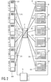
- Fig. 2 shows a second embodiment of the system for use as a multichannel disk digital video recorder.
- This embodiment includes six storage arrays 20.1-20.6, six video I/O access modules 22.1-22.6, a commutator 24 and a host controller 26 in the form of a micro-computer.
- This system behaves as six independent VTRs with the distinction that the stored data is in a common pool which is accessible to all six "video heads".
- Each video module acts as either a record head or a playback head on this common data pool. It is of course possible that the video module may operate in both record and playback simultaneously. All six "video heads” can access this common pool simultaneously, in a manner conducive to non-linear editing. Any "video head” can switch between playback and record on any field boundary.
- each field recorded from any of the six video channels is "sprayed" onto all 72 disk drives, so that each drive holds 1/72nd of each recorded field.
- all 72 disk drives work in parallel to fetch the data for that field.
- the maximum disk bandwidth is utilized on every field access.
- the commutator 24 is what allows the data for each video channel to be delivered to or from all six storage arrays 20.1-20.6.
- the commutator is like a 6-pole rotating switch which switches to a new position, for example, six times per video field, causing each field to be spread onto all six storage arrays.
- the commutator is shown in one of its six possible positions.
- Fig. 3 shows an embodiment of such a system which includes four storage arrays 30.1-30.4, commutator 32, an input/output access module 34, and three video output access modules 36.1-36.3.
- this system dedicates one access channel, input/output access module 34, exclusively for the task of high-speed loading of data into the system, while the system continues to operate on the other channels.
- a telecine 38 is shown for the transfer of film to video. The output from the telecine 38 is coupled to the input/output access module 34 through a digital video compression circuit 40.
- each of the video output access modules 36.1-36.3 includes a demultiplexer 46 coupling the bus from the commutator to a plurality of sub-channels 48 corresponding to the sub-channels of information retrieved from the storage arrays. These sub-channels 48 are then coupled to an encryption circuit 50 for transmission through a satellite uplink 52.
- a system may require the storage of 1,000 movies on-line and 1,600 movies near-line (i.e., access within 1 minute, for example, stored on tape), which are required to be accessed by 2,000 outputs.
- each disk drive in the storage arrays is capable of storing 2 Gigabytes of information
- the system would require at least 17 storage arrays each having 40 disk drives giving the system a total storage capacity of 1,350 GB.
- the commutator would then have 17 commutating paths connecting to one input/output access module and 16 video output access modules each having 128 demultiplexed sub-channel outputs.
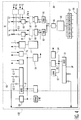
- Fig. 4 shows a detailed block diagram of a typical storage array.
- the storage array is sectioned into three basic blocks: an I/O module 60, a disk module 80, and a host 100.
- the I/O module 60 manages the input and output of video, audio, and control information to and from the external world.
- the input data is converted from video formats to a generic computer data format and is then transmitted to the disk module 80, as shown on the center right side of the figure.
- this generic data is returned by the disk module 80, and is converted back to video/audio data by the I/O module 60.
- the I/O module is controlled by a microprocessor 61, Motorola 68302 CPU.
- This microprocessor contains a standard 68000 "core” and three high-speed serial channels 62.1-62.3. Each channel connects to a serial line, as shown at the top of the figure ("Serial I/O").
- Serial I/O Serial I/O
- the small squares indicate LocalTalk adapters which in effect convert the serial line to a local area network (e.g., AppleTalk).
- One serial line 62.1 is used for machine control. This allows the storage array to emulate a standard VTR. Timecode and GPI functions are also associated with machine control.
- a second serial line 62.2 goes to a control panel which allows manual operation of the storage array.
- the third serial line 62.3 connects directly to a serial line on the microprocessor in the disk module.
- An Ethernet interface 63 provides for the transfer of image data between the storage array and a system controller.
- a set of control and status registers 64 allows the 68302 to manage the flow of data in the data path section on the upper right side of the figure.
- YC normal picture channel
- K key data
- c the extra color information which is combined with the C of YC. It is also possible to operate in an RGB 4:4:4 mode.
- the INT boxes 66 represent temporal and spatial field interpolators. These operate only on outgoing video data.
- the BRR boxes 67 denote a possible place for adding Bit Rate Reduction hardware to the system.
- the PACK boxes 68 are where the video formatted data is converted to generic 32-bit-wide computer data, and where sync data is removed from the data stream. This packing function allows for efficient data storage in both 8-bit and 10-bit video modes.
- Data then flows into a set of FIFO RAM buffers 69 which allows for quasi-frame synchronization on the inputs. Data then transfers from the FRAM buffers into the disk module.
- the disk module 80 transfers the generic computer data from the I/O module 60 to and from a set of Fast SCSI-2 (Small Computer Standard Interface) disk drives.
- the disk drives are controlled by NCR SCSI controller chips, which are in turn managed by a second Motorola 68302 CPU processor 81, with its associated FLASH RAM 82 and Static SRAM 83.
- this 68302 has three serial channels: one goes to the other 68302 in the I/O module, the second is used as a Maintenance Panel access point for debug purposes, and the third is unused.
- the PORTS box 84 indicates the registers used to control the data path on the lower right.
- Data from the I/O module 60 enters the disk module and passes through an error correction circuit EC 85.
- error correction circuit EC 85 redundant data is generated which protects the user against the failure of any single SCSI disk drive.
- the error-corrected data is then fed into a segment buffer 86, where large "segments" of generic data are accumulated for writing to disk.
- the data segments are steered to one of several NCR SCSI controller chips 87. In turn, these chips direct the data to one of several SCSI-2 drives 88 which are connected to each SCSI bus.
- the data segments must be large so as to minimize the overhead cost of disk seek times. Multiple fields of video data are written in a single shot.
- the host 100 represents a set of software management and control processes which run on the 68302 CPU of the I/O module 60. For this reason, in the figure, the 68302 CPU processor of the I/O module and its associated FLASH and DRAM memory are extended into the host part of the figure.
- the I/O module 60 may be obviated.
- the purpose of the commutator is to interconnect the storage arrays and the I/O access channels.
- the concept of the system is such that each I/O access channel will access many or all of the storage arrays in a repeated sequential manner. An I/O access channel will only access one storage array at a given time, then it will access the next storage array in the sequence, continuing through the full sequence.
- the other I/O access channels in the complete system are also being sequentially switched to the storage arrays, such that all of the active I/O access channels access each of the active storage arrays on a time shared basis.
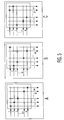
- the commutator may be implemented as a cross-point matrix switch.
- the cross-point matrix switch has a number of inputs, designated by "N” in Figs 5a-5e, and a number of outputs, designated by "M” in the figures.
- Cross-point matrix switches allow any output to be connected to any single input at any time and in any combination.
- An example of a cross-point matrix switch is the 16X16 Digital Crosspoint Switch No. TQ8016, made by TQS Digital Communications and Signal Processing. This switch is capable of handling a 1.3 Gbit/s data rate as a minimum. A user of this switch may independently configure any switch output to any input, including an input chosen by another output.
- the controller 44 of Fig. 3 (or host computer 26 of Fig. 2) is programmed to periodically generate the appropriate output addresses for the inputs of the switch to, in effect, commutate the switch cyclically through each of the connections.
- Figs. 5a-5e illustrate the operation of a cross-point matrix switch when used as a commutator, with the "X" marks indicating the cross-points that have been turned on making a connection from the designated input to the designated output.
- Fig. 5a shows a possible starting condition where output 1 is connected to input 1, output 2 is connected to input 2, etc.
- Fig. 5b shows a configuration for the next position where output 1 is connected to input 2, output 2 is connected to input 3, etc., with output M being connected to input 1.
- Figs. 5c and 5d show the next two conditions, while Fig. 5e shows the condition just prior to the sequence repeating and making the connections shown in Fig. 5a.
- the data stored in the storage arrays may be digital or analog in nature.
- Digitally stored data may be generic data normally associated with a computer file system, or it may be a digital representation of video and/or audio signals. Regardless of what the data represents, it may be stored in a compressed format for dense recording, and may be decompressed on playback.
- a given system is readily expandable by using a commutator with more commutating paths and by adding additional storage arrays and input/output access channels.
- the trunk lines going to the commutator may be bi-directional read/write lines, or they may be dedicated read-only or write-only lines. Correspondingly, some access channels may be read-only or write-only.
- Each trunk line may be a single wire, or may be a cable containing more than one wire. Alternatively, each trunk line may be one or more optical fibers, the commutator then being an optical switching device.
Abstract
Description
- The subject invention relates to the problem of providing simultaneous access for a number of users to a mass storage medium.
- One of the advantages of present day cable television is the provision of pay-per-view features. However, a drawback is that the viewer is locked into viewing the program at the time that the feature is provided by the cable supplier.
- A new service being proposed is video-on-demand where, for example, a movie selected by the user is provided to that user when desired by the user. One problem in implementing this type system is being able to store a large number of individual movies effectively. Another problem is being able to access and deliver these stored individual movies to different users.
- The first problem may be addressed by the various data compression schemes in which the video information is digitized and then compressed (JPEG, MPEG, etc.). This compressed data may then be stored in a mass storage medium.
- The second problem is more problematical. There are various proposals for constructing a bus system ("big bus") for connecting the mass storage medium to a distribution system, e.g. a cable system. However, the design of this "big bus" is very complicated and is not subject to expansion. In particular, to achieve a high data bandwidth, the "big bus" would have to incorporate costly ultra-high speed components, since a bus has only one data path. In addition, in a high-bandwidth parallel digital bus type system having many data lines, devices attached to the bus must be physically close to the bus, and the bus can have only a limited physical length. Furthermore, such a bus would be very expensive.
- It is an object of the present invention to provide a system of the above type which is easily expandable.
- It is a further object of the present invention to provide such a system in a more economical fashion.
- The above objects are achieved in a system for storing large amounts of data and for providing simultaneous plural access to said data, said system comprising a mass storage medium having a number N of individual storage arrays for storing said data, each of said individual storage arrays having input/output means; an access medium having a corresponding number N of access channels, each of said access channels having input/output means; a commutator having a corresponding number N of commutation paths, each of said paths connecting the input/output means of one of said individual storage arrays with the input/output means of one of said access channels; and control means for causing said commutator to cyclically switch said commutation paths such that

where t is the time spent at each position of the commutator and T is the amount of time for one of the access channels to have been connected to each and every one of the N number of storage arrays. - The subject invention is a distributed record/playback (write/read) storage system in which each data segment (file) is sub-divided into smaller data blocks which are written in cyclic fashion onto a set of storage arrays. The data so stored can be randomly accessed (for read and/or write) simultaneously by a multitude of access channels. These channels connect to the multiple storage arrays by means of a cyclic switching device called a commutator. The commutator repeats a cyclic pattern of "positions" such that, during each cycle, each access channel is connected to each storage array for some amount of time.
- The subject invention solves the problem of allowing multiple channels to have high-bandwidth (real-time in the case of video) access into a common data pool in which each item is recorded only once, thus saving storage space and cost. Multiple storage arrays are necessary due to the large amount of data storage and data bandwidth required in many applications. Multiple simultaneous access channels are desirable because many "users" often wish to have independent access to all the data, as is the case with a conventional network computer "file server". However, in such a conventional file server, users must share the bandwidth of the network. The invention, in effect, provides each user with a full bandwidth private channel to all the data.
- Since the invention has multiple access channels, one or more of these can be dedicated all the time (or some of the time) to the task of high-speed loading of data into the system, as the system continues to operate on its other channels. This is not possible with a conventional network file server where the single access channel must be time-shared between the loading function and normal access functions.
- The subject invention is similar to the generally known RAID (Random Array of Independent Disks) method for storing computer data by distributing it on multiple disk drives. However a significant difference is that the RAID systems have only one access channel, whereas the subject invention supports a multitude of simultaneous access channels, each of which has access to the entire data pool.
- With the above and additional objects and advantages in mind as will hereinafter appear, the invention will be described with reference to the accompanying drawings, in which:
- Fig. 1 shows a simplified block diagram of a first embodiment of the system having two input/output access channels and two storage arrays;
- Fig. 2 shows a block diagram of a second embodiment of the system having six input/output access modules and six storage arrays for use as a multi-channel disk recorder;
- Fig. 3 shows a block diagram of a third embodiment of the system having three output access modules, one input/output access module and four storage arrays for use in a video supply system;
- Fig. 4 shows a detailed block diagram of a typical storage array; and
- Figs. 5a-5e show the various switching positions of an embodiment of the commutator in the form of a cross-point matrix switch.
- The system of the subject invention is basically shown in Fig. 1. Therein, the system includes two storage arrays 10.1 and 10.2, two input/output I/O access channels 12.1 and 12.2, and a
commutator 14 for connecting the storage arrays to the I/O access channels. Under the control of a controller (not shown), thecommutator 14 repetitively and alternately connects the I/O access channel 12.1 to the storage arrays 10.1 and 10.2, respectively, while simultaneously, repetitively and alternately connecting the I/O access channel 12.2 to the storage arrays 10.2 and 10.1, respectively. Depending on the cycle time of thecommutator 14, each I/O access channel 12.1 and 12.2 has access to all of the stored data. - Fig. 2 shows a second embodiment of the system for use as a multichannel disk digital video recorder. This embodiment includes six storage arrays 20.1-20.6, six video I/O access modules 22.1-22.6, a
commutator 24 and a host controller 26 in the form of a micro-computer. This system behaves as six independent VTRs with the distinction that the stored data is in a common pool which is accessible to all six "video heads". Each video module acts as either a record head or a playback head on this common data pool. It is of course possible that the video module may operate in both record and playback simultaneously. All six "video heads" can access this common pool simultaneously, in a manner conducive to non-linear editing. Any "video head" can switch between playback and record on any field boundary. Assuming for the moment that error correction is turned off and there is no data compression, each storage array, which includes twelvedisk drives 28, can store, for example, 8 minutes of 10-bit D1 digital video data, so that the total system storage is 6X8 = 48 minutes. The data is stored on 6X12 = 72 disk drives. In fact, each field recorded from any of the six video channels is "sprayed" onto all 72 disk drives, so that each drive holds 1/72nd of each recorded field. Thus, when any field is read from the disk system, all 72 disk drives work in parallel to fetch the data for that field. Thus, the maximum disk bandwidth is utilized on every field access. - The
commutator 24 is what allows the data for each video channel to be delivered to or from all six storage arrays 20.1-20.6. The commutator is like a 6-pole rotating switch which switches to a new position, for example, six times per video field, causing each field to be spread onto all six storage arrays. In Fig. 2, the commutator is shown in one of its six possible positions. - As noted above, it is contemplated that the system be used in a video-on-demand system. Fig. 3 shows an embodiment of such a system which includes four storage arrays 30.1-30.4,
commutator 32, an input/output access module 34, and three video output access modules 36.1-36.3. As noted above, this system dedicates one access channel, input/output access module 34, exclusively for the task of high-speed loading of data into the system, while the system continues to operate on the other channels. To this end, atelecine 38 is shown for the transfer of film to video. The output from thetelecine 38 is coupled to the input/output access module 34 through a digitalvideo compression circuit 40. Additionally, tape cartridges containing video information may be loaded into the system via thetape drive arrangement 42 also coupled to the input/output access module 34. Each of the above devices are controlled bycontroller 44. While this embodiment shows three channels for outputting the stored video information, it should be recognized that significantly greater capacity may be had through the use of multiplexing. In particular, during each cycle of transfer of information from the various storage arrays, multiple sub-channels of information may be multiplexed. To this end, each of the video output access modules 36.1-36.3 includes ademultiplexer 46 coupling the bus from the commutator to a plurality of sub-channels 48 corresponding to the sub-channels of information retrieved from the storage arrays. These sub-channels 48 are then coupled to anencryption circuit 50 for transmission through asatellite uplink 52. - In a practical implementation of the above embodiment, a system may require the storage of 1,000 movies on-line and 1,600 movies near-line (i.e., access within 1 minute, for example, stored on tape), which are required to be accessed by 2,000 outputs. Assuming that each disk drive in the storage arrays is capable of storing 2 Gigabytes of information, the system would require at least 17 storage arrays each having 40 disk drives giving the system a total storage capacity of 1,350 GB. The commutator would then have 17 commutating paths connecting to one input/output access module and 16 video output access modules each having 128 demultiplexed sub-channel outputs.
- Fig. 4 shows a detailed block diagram of a typical storage array. The storage array is sectioned into three basic blocks: an I/
O module 60, adisk module 80, and ahost 100. The I/O module 60 manages the input and output of video, audio, and control information to and from the external world. The input data is converted from video formats to a generic computer data format and is then transmitted to thedisk module 80, as shown on the center right side of the figure. During the play process, this generic data is returned by thedisk module 80, and is converted back to video/audio data by the I/O module 60. The I/O module is controlled by amicroprocessor 61,Motorola 68302 CPU. This microprocessor contains a standard 68000 "core" and three high-speed serial channels 62.1-62.3. Each channel connects to a serial line, as shown at the top of the figure ("Serial I/O"). The small squares indicate LocalTalk adapters which in effect convert the serial line to a local area network (e.g., AppleTalk). - One serial line 62.1 is used for machine control. This allows the storage array to emulate a standard VTR. Timecode and GPI functions are also associated with machine control.
- A second serial line 62.2 goes to a control panel which allows manual operation of the storage array.
- The third serial line 62.3 connects directly to a serial line on the microprocessor in the disk module.
- An
Ethernet interface 63 provides for the transfer of image data between the storage array and a system controller. - A set of control and status registers 64 (PORTS) allows the 68302 to manage the flow of data in the data path section on the upper right side of the figure.
- At the top of the data path are two 601-style video inputs and outputs 65. These are labeled YC for the normal picture channel, and Kc for the extra channel. In 4:2:2:2 mode, K is the key data. In 4:4:4 mode, c is the extra color information which is combined with the C of YC. It is also possible to operate in an RGB 4:4:4 mode.
- The
INT boxes 66 represent temporal and spatial field interpolators. These operate only on outgoing video data. TheBRR boxes 67 denote a possible place for adding Bit Rate Reduction hardware to the system. ThePACK boxes 68 are where the video formatted data is converted to generic 32-bit-wide computer data, and where sync data is removed from the data stream. This packing function allows for efficient data storage in both 8-bit and 10-bit video modes. - Data then flows into a set of FIFO RAM buffers 69 which allows for quasi-frame synchronization on the inputs. Data then transfers from the FRAM buffers into the disk module.
- Four channels of analog audio data are digitized (16-bits/channel, 48KHz) in audio A/
D 70 and are buffered inaudio frame store 71 and then appended to the generic data in one of the FRAMs. - The
disk module 80 transfers the generic computer data from the I/O module 60 to and from a set of Fast SCSI-2 (Small Computer Standard Interface) disk drives. The disk drives are controlled by NCR SCSI controller chips, which are in turn managed by asecond Motorola 68302CPU processor 81, with its associatedFLASH RAM 82 andStatic SRAM 83. As with the I/O module, this 68302 has three serial channels: one goes to the other 68302 in the I/O module, the second is used as a Maintenance Panel access point for debug purposes, and the third is unused. ThePORTS box 84 indicates the registers used to control the data path on the lower right. - Data from the I/
O module 60 enters the disk module and passes through an errorcorrection circuit EC 85. Here, redundant data is generated which protects the user against the failure of any single SCSI disk drive. The error-corrected data is then fed into asegment buffer 86, where large "segments" of generic data are accumulated for writing to disk. The data segments are steered to one of several NCR SCSI controller chips 87. In turn, these chips direct the data to one of several SCSI-2drives 88 which are connected to each SCSI bus. - The data segments must be large so as to minimize the overhead cost of disk seek times. Multiple fields of video data are written in a single shot.
- During playback mode, data is retrieved from the disks and placed into the segment buffer. If any disk drive has failed, the error correction circuit reconstitutes the original data stream, and the corrected data is then fed back to the I/
O module 60. The system continues to operate as if no failure occurred, and the user is notified that a failed drive should be replaced at the next maintenance opportunity. - The
host 100 represents a set of software management and control processes which run on the 68302 CPU of the I/O module 60. For this reason, in the figure, the 68302 CPU processor of the I/O module and its associated FLASH and DRAM memory are extended into the host part of the figure. - In the above description, it has been assumed that the data supplied to the storage array is in analog form. However, in a proposed system where the data is already in generic digital form, the I/
O module 60 may be obviated. - The purpose of the commutator is to interconnect the storage arrays and the I/O access channels. The concept of the system is such that each I/O access channel will access many or all of the storage arrays in a repeated sequential manner. An I/O access channel will only access one storage array at a given time, then it will access the next storage array in the sequence, continuing through the full sequence. The other I/O access channels in the complete system are also being sequentially switched to the storage arrays, such that all of the active I/O access channels access each of the active storage arrays on a time shared basis.
- The commutator may be implemented as a cross-point matrix switch. The cross-point matrix switch has a number of inputs, designated by "N" in Figs 5a-5e, and a number of outputs, designated by "M" in the figures. Cross-point matrix switches allow any output to be connected to any single input at any time and in any combination. An example of a cross-point matrix switch is the 16X16 Digital Crosspoint Switch No. TQ8016, made by TQS Digital Communications and Signal Processing. This switch is capable of handling a 1.3 Gbit/s data rate as a minimum. A user of this switch may independently configure any switch output to any input, including an input chosen by another output. To this end, the
controller 44 of Fig. 3 (or host computer 26 of Fig. 2) is programmed to periodically generate the appropriate output addresses for the inputs of the switch to, in effect, commutate the switch cyclically through each of the connections. - Figs. 5a-5e illustrate the operation of a cross-point matrix switch when used as a commutator, with the "X" marks indicating the cross-points that have been turned on making a connection from the designated input to the designated output. Fig. 5a shows a possible starting condition where
output 1 is connected to input 1,output 2 is connected to input 2, etc. Fig. 5b shows a configuration for the next position whereoutput 1 is connected to input 2,output 2 is connected to input 3, etc., with output M being connected toinput 1. Figs. 5c and 5d show the next two conditions, while Fig. 5e shows the condition just prior to the sequence repeating and making the connections shown in Fig. 5a. - The data stored in the storage arrays may be digital or analog in nature. Digitally stored data may be generic data normally associated with a computer file system, or it may be a digital representation of video and/or audio signals. Regardless of what the data represents, it may be stored in a compressed format for dense recording, and may be decompressed on playback.
- A given system is readily expandable by using a commutator with more commutating paths and by adding additional storage arrays and input/output access channels. The trunk lines going to the commutator may be bi-directional read/write lines, or they may be dedicated read-only or write-only lines. Correspondingly, some access channels may be read-only or write-only. Each trunk line may be a single wire, or may be a cable containing more than one wire. Alternatively, each trunk line may be one or more optical fibers, the commutator then being an optical switching device.
- Numerous alterations and modifications of the structure herein disclosed will present themselves to those skilled in the art. However, it is to be understood that the above described embodiment is for purposes of illustration only and not to be construed as a limitation of the invention. All such modifications which do not depart from the spirit of the invention are intended to be included within the scope of the appended claims.
Claims (12)
- A system for storing large amounts of data and for providing simultaneous plural access to said stored data, said system comprising:
a mass storage medium having a number N of individual storage arrays for storing said data, each of said storage arrays having input/output means;
an access medium having a corresponding number N of access channels, each of said access channels having input/output means;
a commutator having a corresponding number N of commutation paths, each of said paths connecting the input/output means of one of said number of individual storage arrays with the input/output means of one of said access channels; and
control means for causing said commutator to cyclically switch said commutation paths such that
- A system as claimed in claim 1, wherein each of said storage arrays comprises a plurality of storage sections each having an input/output line, said input/output means comprising said input/output lines in combination, thereby enabling plural access to said storage sections in parallel.
- A system as claimed in claim 2, wherein each of said access channels comprises a plurality of access sub-channels each having an input/output line, said input/output means comprising said input/output lines in combination, thereby enabling parallel processing by said access sub-channels of data accessed from said storage sections in parallel.
- A system as claimed in claim 1, wherein said data is recorded onto said storage medium in segments distributed sequentially among said storage arrays, each of said segments being wholly accessible within said time t, whereby each of said access channels may access the same data within a time period of (N-1) X t.
- A system as claimed in claim 2, wherein said storage sections are magnetic disks.
- A system as claimed in claim 2, wherein said data is written into at least two of said sections redundantly.
- A system as claimed in claim 5, wherein said data is written into at least two of said sections redundantly.
- A system as claimed in claim 1, wherein said data is compressed video data representing a plurality of movies.
- A system as claimed in claim 8, wherein said access medium is part of a cable television system.
- A system as claimed in claim 3, wherein said input/output lines of said storage sections and said access sub-channels have a first bit rate, and said control means causes said data to be transferred from said storage sections to said access sub-channels at said first bit rate during each time t, each of said access sub-channels including a access line having a second bit rate, slower than said first bit rate, for providing the data, and a buffer memory for temporarily storing the data accessed from the storage sections to compensate for the dissimilarity between the first and the second bit rates.
- A system as claimed in claim 11, wherein the commutator is a cross-point matrix switch having a plurality of inputs and outputs, connecting means for selectively connecting said inputs to said outputs, and addressing means for controlling said connecting means, said addressing means having an address input, and wherein said control means includes means for generating addresses for application to the address input of said addressing means for causing said cross-point matrix switch to commutate by cyclically connecting each of said inputs to each of said outputs.
- A system as claimed in claim 1, wherein the commutator is arranged for switching optical signals.
Applications Claiming Priority (2)
| Application Number | Priority Date | Filing Date | Title |
|---|---|---|---|
| US08/125,996 US5539660A (en) | 1993-09-23 | 1993-09-23 | Multi-channel common-pool distributed data storage and retrieval system |
| US125996 | 1993-09-23 |
Publications (2)
| Publication Number | Publication Date |
|---|---|
| EP0646874A1 true EP0646874A1 (en) | 1995-04-05 |
| EP0646874B1 EP0646874B1 (en) | 2001-12-05 |
Family
ID=22422452
Family Applications (1)
| Application Number | Title | Priority Date | Filing Date |
|---|---|---|---|
| EP94202712A Expired - Lifetime EP0646874B1 (en) | 1993-09-23 | 1994-09-21 | Multi-channel common-pool distributed data storage and retrieval system |
Country Status (4)
| Country | Link |
|---|---|
| US (1) | US5539660A (en) |
| EP (1) | EP0646874B1 (en) |
| JP (1) | JPH07152500A (en) |
| DE (1) | DE69429320T2 (en) |
Cited By (5)
| Publication number | Priority date | Publication date | Assignee | Title |
|---|---|---|---|---|
| GB2312318A (en) * | 1996-04-15 | 1997-10-22 | Discreet Logic Inc | Video data storage |
| WO1997041515A2 (en) * | 1996-04-29 | 1997-11-06 | Philips Electronics N.V. | An advanced data server with an i/o ring coupled to a disc array ring |
| EP0837607A2 (en) * | 1996-10-18 | 1998-04-22 | Canon Kabushiki Kaisha | Server system for delivering signal and delivery method of signal therein |
| EP0936559A2 (en) * | 1998-02-17 | 1999-08-18 | Sony Corporation | Video data storage and video data transmitter as well as method to be used with the same |
| GB2386738A (en) * | 2002-03-18 | 2003-09-24 | Hewlett Packard Co | Playing and changeover of fast and slow access media |
Families Citing this family (30)
| Publication number | Priority date | Publication date | Assignee | Title |
|---|---|---|---|---|
| US5671386A (en) * | 1993-09-23 | 1997-09-23 | Philips Electronics North America Corporation | System for storing data and for providing simultaneous plural access to data by connecting each access channel to each and every one of storage arrays |
| US5878280A (en) * | 1993-09-23 | 1999-03-02 | Philips Electronics North America Corp. | Data buffering system for plural data memory arrays |
| US6003071A (en) * | 1994-01-21 | 1999-12-14 | Sony Corporation | Image data transmission apparatus using time slots |
| GB2299422B (en) * | 1995-03-30 | 2000-01-12 | Sony Uk Ltd | Object code allocation in multiple processor systems |
| US5948062A (en) * | 1995-10-27 | 1999-09-07 | Emc Corporation | Network file server using a cached disk array storing a network file directory including file locking information and data mover computers each having file system software for shared read-write file access |
| US6061504A (en) * | 1995-10-27 | 2000-05-09 | Emc Corporation | Video file server using an integrated cached disk array and stream server computers |
| US5933603A (en) * | 1995-10-27 | 1999-08-03 | Emc Corporation | Video file server maintaining sliding windows of a video data set in random access memories of stream server computers for immediate video-on-demand service beginning at any specified location |
| US6018765A (en) * | 1996-01-23 | 2000-01-25 | Storage Concepts, Inc. | Multi-channel multimedia data server |
| US5832198A (en) * | 1996-03-07 | 1998-11-03 | Philips Electronics North America Corporation | Multiple disk drive array with plural parity groups |
| US6128467A (en) * | 1996-03-21 | 2000-10-03 | Compaq Computer Corporation | Crosspoint switched multimedia system |
| US5815583A (en) * | 1996-06-28 | 1998-09-29 | Intel Corporation | Audio serial digital interconnect |
| US5859976A (en) * | 1996-07-29 | 1999-01-12 | Philips Electronics North America Corporation | System and method for enabling a data/video server to implement operation in accordance with a new connection diagram, and a data/video server including that system |
| US6298386B1 (en) | 1996-08-14 | 2001-10-02 | Emc Corporation | Network file server having a message collector queue for connection and connectionless oriented protocols |
| US5893140A (en) * | 1996-08-14 | 1999-04-06 | Emc Corporation | File server having a file system cache and protocol for truly safe asynchronous writes |
| US5870553A (en) * | 1996-09-19 | 1999-02-09 | International Business Machines Corporation | System and method for on-demand video serving from magnetic tape using disk leader files |
| US6553476B1 (en) | 1997-02-10 | 2003-04-22 | Matsushita Electric Industrial Co., Ltd. | Storage management based on predicted I/O execution times |
| US6185621B1 (en) * | 1997-03-25 | 2001-02-06 | Philips Electronics N.A. Corp. | Direct copying between disk blocks in memory onto a network as sequential access files |
| US6442604B2 (en) * | 1997-03-25 | 2002-08-27 | Koninklijke Philips Electronics N.V. | Incremental archiving and restoring of data in a multimedia server |
| US5892915A (en) * | 1997-04-25 | 1999-04-06 | Emc Corporation | System having client sending edit commands to server during transmission of continuous media from one clip in play list for editing the play list |
| US5987621A (en) * | 1997-04-25 | 1999-11-16 | Emc Corporation | Hardware and software failover services for a file server |
| US5974503A (en) * | 1997-04-25 | 1999-10-26 | Emc Corporation | Storage and access of continuous media files indexed as lists of raid stripe sets associated with file names |
| US6044442A (en) * | 1997-11-21 | 2000-03-28 | International Business Machines Corporation | External partitioning of an automated data storage library into multiple virtual libraries for access by a plurality of hosts |
| JP2002515701A (en) * | 1998-05-08 | 2002-05-28 | クゥアルコム・インコーポレイテッド | Apparatus and method for distributing high quality image and high sound quality programs to remote locations |
| US8813137B2 (en) | 1998-05-08 | 2014-08-19 | Qualcomm Incorporated | Apparatus and method for decoding digital image and audio signals |
| US20020157113A1 (en) * | 2001-04-20 | 2002-10-24 | Fred Allegrezza | System and method for retrieving and storing multimedia data |
| US7552192B2 (en) * | 2002-12-18 | 2009-06-23 | Ronnie Gerome Carmichael | Massively parallel computer network-utilizing MPACT and multipoint parallel server (MPAS) technologies |
| US20050175803A1 (en) * | 2004-02-06 | 2005-08-11 | D. Ryan Breese | Preparation of polyethylene films |
| US8688780B2 (en) * | 2005-09-30 | 2014-04-01 | Rockwell Automation Technologies, Inc. | Peer-to-peer exchange of data resources in a control system |
| US20080170571A1 (en) * | 2007-01-12 | 2008-07-17 | Utstarcom, Inc. | Method and System for Synchronous Page Addressing in a Data Packet Switch |
| DE102013200171A1 (en) * | 2013-01-09 | 2014-07-10 | Lufthansa Technik Ag | Data network, method and player for reproducing audio and video data in an in-flight entertainment system |
Citations (2)
| Publication number | Priority date | Publication date | Assignee | Title |
|---|---|---|---|---|
| EP0208319A2 (en) * | 1985-07-12 | 1987-01-14 | Wang Laboratories, Inc. | A system for providing selective interconnection between a plurality of ports |
| WO1991014229A1 (en) * | 1990-03-09 | 1991-09-19 | Sf2 Corporation | Apparatus and method for communication in a data processing system |
Family Cites Families (8)
| Publication number | Priority date | Publication date | Assignee | Title |
|---|---|---|---|---|
| FR2468990A1 (en) * | 1979-08-16 | 1981-05-08 | France Etat | SWITCH WITH MULTIPLE CROSSPOINT LAYERS |
| FR2623682A1 (en) * | 1987-11-24 | 1989-05-26 | Cgv Comp Gen Videotech | SWITCHING GRID |
| US4949187A (en) * | 1988-12-16 | 1990-08-14 | Cohen Jason M | Video communications system having a remotely controlled central source of video and audio data |
| US5163131A (en) * | 1989-09-08 | 1992-11-10 | Auspex Systems, Inc. | Parallel i/o network file server architecture |
| US5179552A (en) * | 1990-11-26 | 1993-01-12 | Bell Communications Research, Inc. | Crosspoint matrix switching element for a packet switch |
| US5311423A (en) * | 1991-01-07 | 1994-05-10 | Gte Service Corporation | Schedule management method |
| US5371532A (en) * | 1992-05-15 | 1994-12-06 | Bell Communications Research, Inc. | Communications architecture and method for distributing information services |
| US5341474A (en) * | 1992-05-15 | 1994-08-23 | Bell Communications Research, Inc. | Communications architecture and buffer for distributing information services |
-
1993
- 1993-09-23 US US08/125,996 patent/US5539660A/en not_active Expired - Lifetime
-
1994
- 1994-09-21 DE DE69429320T patent/DE69429320T2/en not_active Expired - Fee Related
- 1994-09-21 EP EP94202712A patent/EP0646874B1/en not_active Expired - Lifetime
- 1994-09-22 JP JP6228153A patent/JPH07152500A/en active Pending
Patent Citations (2)
| Publication number | Priority date | Publication date | Assignee | Title |
|---|---|---|---|---|
| EP0208319A2 (en) * | 1985-07-12 | 1987-01-14 | Wang Laboratories, Inc. | A system for providing selective interconnection between a plurality of ports |
| WO1991014229A1 (en) * | 1990-03-09 | 1991-09-19 | Sf2 Corporation | Apparatus and method for communication in a data processing system |
Cited By (12)
| Publication number | Priority date | Publication date | Assignee | Title |
|---|---|---|---|---|
| GB2312318A (en) * | 1996-04-15 | 1997-10-22 | Discreet Logic Inc | Video data storage |
| GB2312318B (en) * | 1996-04-15 | 1998-11-25 | Discreet Logic Inc | Video data storage |
| WO1997041515A2 (en) * | 1996-04-29 | 1997-11-06 | Philips Electronics N.V. | An advanced data server with an i/o ring coupled to a disc array ring |
| WO1997041515A3 (en) * | 1996-04-29 | 1997-12-24 | Philips Electronics Nv | An advanced data server with an i/o ring coupled to a disc array ring |
| EP0837607A2 (en) * | 1996-10-18 | 1998-04-22 | Canon Kabushiki Kaisha | Server system for delivering signal and delivery method of signal therein |
| EP0837607A3 (en) * | 1996-10-18 | 2002-01-09 | Canon Kabushiki Kaisha | Server system for delivering signal and delivery method of signal therein |
| EP0936559A2 (en) * | 1998-02-17 | 1999-08-18 | Sony Corporation | Video data storage and video data transmitter as well as method to be used with the same |
| EP0936559A3 (en) * | 1998-02-17 | 2002-01-23 | Sony Corporation | Video data storage and video data transmitter as well as method to be used with the same |
| US6577814B1 (en) | 1998-02-17 | 2003-06-10 | Sony Corporation | Video data recording and reproduction using time slot allocation |
| GB2386738A (en) * | 2002-03-18 | 2003-09-24 | Hewlett Packard Co | Playing and changeover of fast and slow access media |
| GB2386738B (en) * | 2002-03-18 | 2005-09-21 | Hewlett Packard Co | Media playing |
| US7770199B2 (en) | 2002-03-18 | 2010-08-03 | Hewlett-Packard Development Company, L.P. | Media playing |
Also Published As
| Publication number | Publication date |
|---|---|
| US5539660A (en) | 1996-07-23 |
| EP0646874B1 (en) | 2001-12-05 |
| DE69429320D1 (en) | 2002-01-17 |
| JPH07152500A (en) | 1995-06-16 |
| DE69429320T2 (en) | 2002-08-14 |
Similar Documents
| Publication | Publication Date | Title |
|---|---|---|
| US5539660A (en) | Multi-channel common-pool distributed data storage and retrieval system | |
| EP0756802B1 (en) | Multi-channel common-pool distributed data storage and retrieval system | |
| JP3500165B2 (en) | Video signal storage / processing / distribution method and apparatus | |
| US6798972B1 (en) | Image reproducing apparatus and image reproducing method | |
| EP0691648B1 (en) | Information data recording and reproducing device and information data processing system | |
| US6442604B2 (en) | Incremental archiving and restoring of data in a multimedia server | |
| EP0637890B1 (en) | Modular high-capacity solid-state mass data storage device for video servers | |
| US6185621B1 (en) | Direct copying between disk blocks in memory onto a network as sequential access files | |
| US6434324B1 (en) | Data recording/reproducing apparatus, data recording/reproducing method and data format | |
| US6577814B1 (en) | Video data recording and reproduction using time slot allocation | |
| US6934465B1 (en) | Audio and/or video data recording and reproducing apparatus and method of same | |
| US7016598B2 (en) | Data recording/reproduction apparatus and data recording/reproduction method | |
| US6144796A (en) | Video data system | |
| KR19990088015A (en) | Data recording and reproducing appariatus and method | |
| JP3526153B2 (en) | Data recording / reproducing device | |
| US20010055470A1 (en) | Image recording and reproducing apparatus and image recording and reproducing method | |
| US6351597B2 (en) | Data recording and reproducing method and data recording and reproducing apparatus | |
| JP4325074B2 (en) | Data recording / reproducing apparatus and method | |
| JP2000163867A (en) | Data processing device | |
| JP2000307978A (en) | Data recording and reproducing device and variable- speed reproducing method | |
| Bernstein | Media Pool—Flexible Video Server Design for Television Broadcasting | |
| JP2000149509A (en) | Data recording and reproducing apparatus and method | |
| JPH08317338A (en) | Data transmitter | |
| JP2001292409A (en) | Data recording and reproducing device, and method | |
| JPH11275504A (en) | Data processing unit |
Legal Events
| Date | Code | Title | Description |
|---|---|---|---|
| PUAI | Public reference made under article 153(3) epc to a published international application that has entered the european phase |
Free format text: ORIGINAL CODE: 0009012 |
|
| AK | Designated contracting states |
Kind code of ref document: A1 Designated state(s): DE FR GB |
|
| 17P | Request for examination filed |
Effective date: 19951005 |
|
| 17Q | First examination report despatched |
Effective date: 20000502 |
|
| GRAG | Despatch of communication of intention to grant |
Free format text: ORIGINAL CODE: EPIDOS AGRA |
|
| GRAG | Despatch of communication of intention to grant |
Free format text: ORIGINAL CODE: EPIDOS AGRA |
|
| GRAH | Despatch of communication of intention to grant a patent |
Free format text: ORIGINAL CODE: EPIDOS IGRA |
|
| GRAH | Despatch of communication of intention to grant a patent |
Free format text: ORIGINAL CODE: EPIDOS IGRA |
|
| GRAA | (expected) grant |
Free format text: ORIGINAL CODE: 0009210 |
|
| AK | Designated contracting states |
Kind code of ref document: B1 Designated state(s): DE FR GB |
|
| REG | Reference to a national code |
Ref country code: GB Ref legal event code: IF02 |
|
| REF | Corresponds to: |
Ref document number: 69429320 Country of ref document: DE Date of ref document: 20020117 |
|
| ET | Fr: translation filed | ||
| PLBE | No opposition filed within time limit |
Free format text: ORIGINAL CODE: 0009261 |
|
| STAA | Information on the status of an ep patent application or granted ep patent |
Free format text: STATUS: NO OPPOSITION FILED WITHIN TIME LIMIT |
|
| 26N | No opposition filed | ||
| REG | Reference to a national code |
Ref country code: GB Ref legal event code: 732E |
|
| REG | Reference to a national code |
Ref country code: FR Ref legal event code: TP |
|
| PGFP | Annual fee paid to national office [announced via postgrant information from national office to epo] |
Ref country code: DE Payment date: 20070920 Year of fee payment: 14 |
|
| PGFP | Annual fee paid to national office [announced via postgrant information from national office to epo] |
Ref country code: GB Payment date: 20070829 Year of fee payment: 14 |
|
| PGFP | Annual fee paid to national office [announced via postgrant information from national office to epo] |
Ref country code: FR Payment date: 20070924 Year of fee payment: 14 |
|
| GBPC | Gb: european patent ceased through non-payment of renewal fee |
Effective date: 20080921 |
|
| REG | Reference to a national code |
Ref country code: FR Ref legal event code: ST Effective date: 20090529 |
|
| PG25 | Lapsed in a contracting state [announced via postgrant information from national office to epo] |
Ref country code: DE Free format text: LAPSE BECAUSE OF NON-PAYMENT OF DUE FEES Effective date: 20090401 |
|
| PG25 | Lapsed in a contracting state [announced via postgrant information from national office to epo] |
Ref country code: FR Free format text: LAPSE BECAUSE OF NON-PAYMENT OF DUE FEES Effective date: 20080930 |
|
| PG25 | Lapsed in a contracting state [announced via postgrant information from national office to epo] |
Ref country code: GB Free format text: LAPSE BECAUSE OF NON-PAYMENT OF DUE FEES Effective date: 20080921 |