EP0647840A2 - Method and apparatus for feedbackcontrol of an asymmetric differential pressure transducer - Google Patents
Method and apparatus for feedbackcontrol of an asymmetric differential pressure transducer Download PDFInfo
- Publication number
- EP0647840A2 EP0647840A2 EP94307077A EP94307077A EP0647840A2 EP 0647840 A2 EP0647840 A2 EP 0647840A2 EP 94307077 A EP94307077 A EP 94307077A EP 94307077 A EP94307077 A EP 94307077A EP 0647840 A2 EP0647840 A2 EP 0647840A2
- Authority
- EP
- European Patent Office
- Prior art keywords
- transducing
- pulse
- diaphragm
- transducer
- feedback
- Prior art date
- Legal status (The legal status is an assumption and is not a legal conclusion. Google has not performed a legal analysis and makes no representation as to the accuracy of the status listed.)
- Granted
Links
Images


Classifications
-
- G—PHYSICS
- G01—MEASURING; TESTING
- G01L—MEASURING FORCE, STRESS, TORQUE, WORK, MECHANICAL POWER, MECHANICAL EFFICIENCY, OR FLUID PRESSURE
- G01L11/00—Measuring steady or quasi-steady pressure of a fluid or a fluent solid material by means not provided for in group G01L7/00 or G01L9/00
- G01L11/004—Measuring steady or quasi-steady pressure of a fluid or a fluent solid material by means not provided for in group G01L7/00 or G01L9/00 by the use of counterbalancing forces
- G01L11/008—Measuring steady or quasi-steady pressure of a fluid or a fluent solid material by means not provided for in group G01L7/00 or G01L9/00 by the use of counterbalancing forces electrostatic or electromagnetic counterbalancing forces
Definitions
- the invention is related to a feedback-control method according to the preamble of claim 1 for an asymmetric differential pressure transducer.
- the invention also concerns an apparatus for the feedback-control of an asymmetric differential pressure transducer.
- a micromechanical element kept at a given electric potential can be controlled by an electrostatic force which is generated by means of potential differences applied to the electrodes surrounding the element and the element itself.
- the electrostatic force generated between two electrodes is expressed as: where U is the potential difference between planar electrodes, ⁇ r dielectric coefficient of the medium, dA elementary area element and d distance between the planar electrodes.
- the integration is carried out over the electrode surface.
- a differential pressure transducer can be operated as a servotransducer in an electrically feedback-connected mode.
- p electric ⁇ 0 ⁇ r 2 d 2 ⁇ U pulse 2 ⁇ T pulse ⁇ ⁇ pulse
- U pulse is the amplitude of the pulse train
- T pulse is the pulse width
- f pulse n/T total is the pulse rate (pulses/unit time).
- a linear output voltage is obtained by taking the pulse train output signal via an integrator.
- a pulse-rate modulated signal can be directly processed as a digital signal formed by a bit stream.
- a problem of the pulsed feedback-control scheme is that the pulse train signal fed back as the control signal acts as an AC signal that may affect the capacitance measurement and even saturate the measurement circuits employed in the capacitance measurement.
- a starting point for the design of a pulsed feedback control of an acceleration transducer is to operate appreciably above the transducer natural frequency [p1, a1, a2], whereby the transducer seismic mass by its moment of inertia is not capable of exhibiting a fast response to individual pulses, and thus, the pulsed feedback force effect is averaged.
- the diaphragm natural frequency is significantly higher (typically in the order of 30 - 200 kHz depending on the diaphragm thickness and diameter).
- the diaphragm when operated at atmospheric pressure, the diaphragm is subjected to extremely heavy viscose damping, so again the diaphragm is prevented from responding to individual pulses imposed at a high pulse rate, and also here the pulsed feedback force effect is averaged.
- the invention is based on keeping the transducing diaphragm of an asymmetric pressure transducer in a controlled manner in a constant position by means of a pulsed feedback signal, and by virtue of applying the feedback signal in opposite phases to a split fixed electrode which is divided in two parts to this end, both the difference and sum values of the transducing capacitances can be obtained from which a correction term can further be computed for the change of the dielectric coefficient.
- the invention offers significant benefits.
- the greatest problem in an electrostatically feedback-controlled micromechanical transducer is the dependence of the capacitor gap fill medium on temperature and humidity. Particularly in oil-filled transducers a temperature change causes a change in the dielectric coefficient of the fill medium, and thus, an error in pressure measurement.
- the apparatus according to the invention overcomes such an error source. Another significant benefit is that the electrostatic force effect exerted by the capacitance sensing signal is utilized in the feedback arrangement, and thus, the pulsed feedback signal cannot saturate the capacitance measurement circuits.
- the apparatus according to the invention makes it possible to implement a measurement apparatus that is, besides the differential pressure measurement, also capable of measuring such a quantity as humidity or temperature, for instance, which has a particular relationship with the dielectric coefficient.
- An optimal control of a pressure-transducing diaphragm can be implemented by a suitable design of the electrode geometry.
- Such a measurement method is based on keeping the pressure-transducing diaphragm in a nondeflected state.
- This desirable arrangement is implemented by means of capacitance measurement and electrostatic feedback so that the error signal taken to the control circuit from the measurement circuit is proportional to the capacitance difference between the capacitances formed by the equal-area inner and outer fixed electrodes with the diaphragm electrode, and particularly the error signal is zero when said capacitances are equal.
- the benefits of the method include a minimized temperature dependence of the transducer and a controlled nonlinearity error.
- the AC measurement signal which is used for sensing the capacitances causes an electrostatic force between the diaphragm and the fixed electrode.
- the pulse train employed in the feedback-control of the diaphragm position can also be used for sensing the diaphragm position.
- the combination feedback/sensing system is based on a pressure-transducing conducting diaphragm 1 and a support structure carrying two fixed, concentric electrodes 2 and 3.
- the feedback signal is taken in pulsed form to the fixed electrodes 2 and 3 so that the voltages applied to the fixed center electrode 3 and the fixed outer electrode 2 are in opposite phases referenced to the potential of the diaphragm 1.
- the potential swing induced at the diaphragm 1 by the feedback signal is zero when the two capacitances formed by the inner fixed electrode 3 and the outer fixed electrode 2 with the electrode of the diaphragm 1 are equal.
- the electrostatic forces acting between the diaphragm 1 and the fixed electrodes 2 and 3 are attractive due to the quadratic relationship F ⁇ U2.
- the pressure-transducing diaphragm 1 whose deflection in the diagram is exaggerated for greater clarity is controlled by opposed fixed electrodes 2 and 3.
- the fixed electrodes 2 and 3 are concentric and essentially equal to their effective areas.
- the pressure-transducing diaphragm 1 and the electrode 3 comprise the capacitor C1, while the diaphragm 1 and the electrode 2 comprise the capacitor C2, respectively.
- a ⁇ / ⁇ converter 9 clocked by a clock frequency 4.
- the clock frequency is advantageously in the range of 50 - 300 kHz.
- the output of the ⁇ / ⁇ converter 9 provides directly a pulse rate output signal 25, which simultaneously is the desired pressure difference signal.
- an analog measurement signal is obtained from the analog output 26.
- the amplitude of the pulse rate signal used as the feedback-control signal is modulated by means of a pulse-amplitude modulator 8, from whose output the feedback signal is taken to the electrodes 3 and 2, however, first inverting the signal taken to the electrode 2 by means of an inverter 7.
- the charge amplifier 5 other kinds of capacitance measurement arrangements can also be employed.
- the ⁇ / ⁇ converter can be replaced by any circuit suited for converting a DC signal into a pulsed signal.
- the inverter 7 may be replaced by any means capable of providing two pulse train signals with opposite polarities referenced to the electric potential of the diaphragm 1.
- the embodiment disclosed herein has the benefit that the electrostatic force effect exerted by the measurement signal is utilized in the feedback arrangement and that the pulse-form feedback signal is prevented from causing saturation of the capacitance measurement circuits.
- FIG. 1b an exemplifying embodiment according to the invention is described for the capacitance difference detection method employed in the capacitance bridge as a special case of the general principle illustrated in Fig. 1a.
- the embodiment is constructed around a charge amplifier 5 suited for implementing the transfer function required in the measurement system disclosed herein.
- the capacitor C1 is fed with a positive-polarity pulse train +V0 referenced to the ground potential, and correspondingly, the capacitor C2 is fed with a negative-polarity pulse train -V0.
- the conducting transducing diaphragm 1 is connected to the inverting input 29 of an operational amplifier 28.
- the operational amplifier output 55 is feedback-connected to the inverting input 29 of the operational amplifier 28 via a capacitor C ref,2 . Then, the potential of the transducing diaphragm 1 is determined by the potential of the noninverting input 56 of the operational amplifier 28, which potential in the illustrated case is the ground potential.
- This arrangement fulfills the condition that the diaphragm 1 must be kept at a constant potential. If the two capacitances C1 and C2 of the transducer are equal, a change in the potential of the fixed electrodes 2 and 3 causes only a charge change on the moving transducing diaphragm 1 without any externally detectable potential change.
- the desired transfer function can be realized at frequencies above 10 kHz in a relatively ideal manner.
- the situation can be further improved by adapting a hold circuit or an integrator subsequent to the charge amplifier 5 for storing the output signal level.
- a switch 13 is employed to provide a possibility of switching an in-phase feedback signal to both electrodes 2 and 3 via the terminal 15.
- the charge amplifier 5 can be used for measuring the difference of the sum capacitance C1 + C2 and the reference capacitance C ref , whereby the signal at the output 14 of the charge amplifier 5 is proportional to said difference.
- the electrodes 2 and 3 are taken to opposite polarities with regard to the potential of the diaphragm 1, whereby the switch 12 is in the open position.
- I amp I sensor
- a ⁇ / ⁇ converter is shown suited for converting a DC signal into a pulsed signal.
- the signal to be converted is taken to the quantizer 33 of the converter via an integrator 30, and the quantized output is feedback-connected to an adder 34, where it is subtracted from the input signal to the adder.
- Such a feedback arrangement 32 forces the average value of the quantized signal to follow the average value of the input signal to the converter. The difference of these signals is accumulated in the integrator, thus implementing self-correction.
- a basic charactenstic of the above-described converter circuit is its simplicity: the ⁇ / ⁇ converter comprises an integrator 30, a i-bit A/D converter 31 and a feedback branch via a i-bit D/A converter 32.
- the A/D converter 31 can be realized with the help of, e.g., a limiter (not shown) and a D-flip-flop circuit (not shown) so that D-flip-flop circuit is driven by an external clock frequency 33.
- the D/A converter 32 can be implemented with the help of, e.g., an analog switch driven by a D-flip-flop circuit.
- the external clock frequency 33 determines the pulse width.
- the clock frequency 33 is selected so that the signal frequency remains significantly smaller than the clock frequency 33, whereby oversampling is realized.
- the ratio of the oversampling rate to the signal frequency must be in the order of 100 or higher when a second-order ⁇ / ⁇ converter is used. Then, the quantization noise remains insignificant.
- an integrator 30 comprises a summing point 42 and a delay circuit 41 whose output is feedback-connected to the summing point 42.
- the delay circuit is followed by a quantizing block 43 which corresponds to the A/D converter 31 described above.
- the input signal is taken to the quantizing block 43 via the integrator 30.
- the quantized output signal is feedback-connected to the input side and subtracted there from the input signal to the circuit.
- the feedback arrangement forces the quantized signal to follow the average level of the input signal to the circuit.
- the difference between the average level of the input signal and the digitized output signal is stored in the integrator 30 thus resultingly performing self-correction. If the signal quantization circuit is designed for a binary level output signal, the quantized output signal toggles between two states so that its moving average corresponds to the average level of the input signal.
- a second-order ⁇ / ⁇ converter includes besides the circuitry shown in Fig. 4, a loop comprising a summing point 51 and a delay circuit 50, whereby said loop together with the adder 34 represents the pressure transducer 52 itself.
- the inertia of the differential pressure transducer 52 makes it act as an integrator.
- the feedback arrangement 54 represents the electrostatic pressure and the input 53 stands for the external differential pressure signal.
- the dielectric coefficient can be determined through capacitance measurement.
- the geometrically constant state of the diaphragm can be upheld irrespective of changes in the dielectric coefficient.
- the dielectric coefficient can be determined through the measurement of the sum of the capacitances, and the measurement result can be used for the compensation of the differential pressure error caused by a change in the dielectric coefficient.
- the change in the dielectric coefficient can be compensated for by modulating the pulse amplitude of the feedback signal.
- a benefit with respect to the implementation based on compensation by virtue of pulse-amplitude modulation is herein the linearity achievable by means of the latter method.
- FIG. 6 a block diagram is shown for a total system, in which the feedback arrangement is implemented by means of a pulse signal feedback configuration in which the change in the dielectric coefficient is sensed via highly accurate capacitance measurement and in which the error caused by the dielectric coefficient change in the differential pressure measurement is compensated for by modulating the pulse amplitude.
- the following complementary description discusses only such elements which were omitted from the diagrams of Figs. 1 and 2.
- the dielectric coefficient change is compensated for in the measurement circuit using a linear approximation: 1 + ⁇ r ⁇ r (0) ⁇ 1 + 1 ⁇ 2 ⁇ r ⁇ r (0)
- the amplitude of feedback signal pulse train is controlled by means of an amplifier 16 so that the capacitance C ref of the reference capacitor 11 becomes effectively equal to the sum C1 + C2 of the transducer capacitances.
- the amplifier gain must be set to value (C1 + C2)/C ref .
- the pulse train current signal passing via the reference capacitor C ref becomes equal to the pulse train current signal passing via the parallel-connected transducer capacitances C1 + C2.
- Said gain value is not essential to the spirit of the invention, while definitely the most practical.
- the switch 12 the reference capacitor 11 can be connected on and off in parallel with the measurement circuit capacitances.
- the switch 18 operates synchronized to the switches 12 and 13 and the circuit 21.
- the desired measurement mode is selected by the switch 18.
- the gain A of the feedback loop is controlled by means of the amplifier 20 so that the desired compensation of the dielectric coefficient change is realized.
- the summing amplifier 24 closes the control loop for the amplitude control of the feedback pulse train signal.
- a change in the pulse amplitude compensates for a change in the dielectric coefficient if the following condition is fulfilled:
- the pulse amplitude controlling voltage is stored in circuit 21 for the duration of the capacitance difference measurement.
- the output 25 of the hold circuit 21 provides a voltage proportional to the dielectric coefficient value.
- the displacement position of the diaphragm 1 can be controlled by means of the offset control voltage taken to the offset control circuit 19.
- the offset control voltage permits the selection of the applied external differential pressure at which the output pulse train signal has zero pulse rate. Consequently, the circuit 19 provides the adjustment of the system zero point.
- the base setting of the pulse amplitude is implemented by means of circuit 23.
- This circuit determines the relationship of the output signal pulse rate with the differential pressure applied to the transducer. Alternatively, this adjustment can be called transducer sensitivity calibration.
- the output voltage of the circuit 23 is summed to the compensation voltage in summing point 24.
- the properties of the embodiment according to the invention are summarized as: Besides having a simple configuration, the system is also straightforward to calibrate. Calibration takes place by altering the pulse amplitude and summing the desired offset voltage at the integrator input of the ⁇ / ⁇ converter, whereby the first adjustment alters the response function slope and the latter the zero point. Both adjustments are independent from each other.
- the feedback control of the diaphragm position in a unidirectionally measuring differential pressure transducer is implemented by means of a pulse-rate modulated signal so that same pulse train signal both establishes the electrostatic feedback force and measures the difference and sum of the capacitances C1 and C2.
- the pulse amplitude can be controlled accurately by means of gain control of, e.g., the amplifier 21.
- the adjustments of the pulse amplitude base height (amplifier 20) and the integrator offset (offset control circuit 19) allow the system to be tuned to a desired operating point according to the transducer pressure measurement range.
- the circuit operation is based on two measurement cycles (determined by switch 13), wherein using the charge amplifier 5 the first cycle measures the difference of the capacitances C1 and C2 and the second cycle measures the sum of the capacitances C1 and C2.
- the rate of the feedback pulse train signal during both measurement cycles is controlled to achieve an electrostatic force that keeps the transducer diaphragm in a desired constant state (e.g., nondeflected).
- the pulse train is applied to the inner and outer fixed electrodes at opposite polarities (inverter 7).
- the pulse train is applied to the outer and inner fixed electrodes at the same polarity.
- the capacitance measurement output signal is adjusted so that the output signal pulse amplitude is of the form: U 0/(1 +1 ⁇ 2 ⁇ r / ⁇ r (0) ) whereby the differential pressure range and resolution can be adjusted through controlling the pulse amplitude (circuit 23).
- the center point of the differential pressure range can be adjusted by adjusting the offset of the integrator of the ⁇ / ⁇ converter 9.
- the pulse train signal is formed by means of a switch 17 controlled by the circuit 9.
- the method according to the invention may also be applied to the measurement of the dielectric coefficient. Further, by inserting a dielectric film responsive to, e.g., humidity, the capacitance change caused by the dielectric coefficient change can be utilized to measure the change of such an external variable.
- the transducing diaphragm in a desired geometric shape irrespective of imposed differential pressure level or change in the dielectric coefficient.
- the above-described exemplifying embodiment achieving the desired goal by virtue of applying the feedback control signal to the two fixed electrodes 2 and 3 at opposite phases relative to the conducting diaphragm 1 is not by any means the only solution according to the spirit of the invention.
- the desired charge balance viz. controlled deviation from the balance and corresponding balance of electrostatic forces in the measurement capacitors can be implemented using a desired even number of the fixed electrodes. Namely, an even number of fixed electrodes permits a relaxed selection of control voltage pulse train amplitudes provided that the charge and electrostatic force balance conditions discussed above are fulfilled.
- a term effective area may be defined for the fixed electrodes 2 and 3 of the transducer structure.
Abstract
Description
- The invention is related to a feedback-control method according to the preamble of
claim 1 for an asymmetric differential pressure transducer. - The invention also concerns an apparatus for the feedback-control of an asymmetric differential pressure transducer.
- The following publications are cited as reference to the prior art:
US patents: - [p1] U.S. Pat. No. 5,095,750 (Suzuki et al.)
- [p2] U.S. Pat. No. 4,831,492 (Kuisma).
- [a1] S. Suzuki, S. Tuchitani, K. Sato, S. Ueno, Y. Yokota, M. Sato, M. Esashi, Semiconductor Capacitance-Type Accelerometer with PWM Electrostatic Servo Technique, Sensors and Actuators A21-A23, pp. 316-319, 1990.
- [a2] Y. de Coulon, T. Smith, J. Hermann, M. Chevroulet, F. Rudolf, Design and Test of a Precision Servoaccelerometer with Digital Output, The Proceedings of the 7th International Conference on Solid-State Sensors and Actuators, Yokohama, Japan, 1993, pp. 832-835.
- A micromechanical element kept at a given electric potential can be controlled by an electrostatic force which is generated by means of potential differences applied to the electrodes surrounding the element and the element itself. As known, the electrostatic force generated between two electrodes is expressed as:

where U is the potential difference between planar electrodes, εr dielectric coefficient of the medium, dA elementary area element and d distance between the planar electrodes. The integration is carried out over the electrode surface. On the basis of Eq. (1), the electrostatic force between the electrodes can be interpreted as an electrostatic pressure acting on the electrode surface:
- Next, a differential pressure transducer structure is examined comprising a body structure supporting a fixed electrode and a diaphragm attached at its edges to said body structure and adapted to deflect under an imposed differential pressure. If the deflection of the diaphragm remains extremely small, each surface element of the diaphragm will be subjected to an equally large force effect by both the electrostatic pressure expressed by Eq. (2) and the externally applied physical pressure, which is thus cancelled by the electrostatic pressure at any point of the diaphragm surface, that is, pext = pelectric. This means that a differential pressure transducer can be operated as a servotransducer in an electrically feedback-connected mode.
When the diaphragm is controlled to the nondeflected state, the external pressure can be expressed as:
where Q is the charge on the electrodes. - Such a feedback arrangement is, however, handicapped by three basic problems:
- 1) The relationship between the electrostatic pressure and the feedback control voltage employed as the transducer output voltage is nonlinear on the basis of Eq. (2).
- 2) The equation pext =ε₀εrU²/2d² is valid in a force balance state only when the diaphragm deflection is zero. To identify this state, the diaphragm position must be known.
- 3) The factor linking the feedback voltage to the generated electrostatic pressure is dependent on the dielectric coefficient of the medium between the electrodes.
- A solution to these problems is disclosed in cited patent [p1] and scientific papers [a1,a2]. If the feedback arrangement is implemented using a pulse-width or pulse-rate modulated signal, i.e., with a constant-amplitude pulse (voltage level), a linear relationship can be established between the electrostatic pressure and the duty cycle of the pulse train:

where D=TON/Ttotal, that is, the ratio of the pulse ON time to the total pulse period. Eq. (4) may be further written as:
where Upulse is the amplitude of the pulse train, Tpulse is the pulse width and fpulse = n/Ttotal is the pulse rate (pulses/unit time). In conjunction with pulse-width modulation, a linear output voltage is obtained by taking the pulse train output signal via an integrator. A pulse-rate modulated signal can be directly processed as a digital signal formed by a bit stream. A problem of the pulsed feedback-control scheme is that the pulse train signal fed back as the control signal acts as an AC signal that may affect the capacitance measurement and even saturate the measurement circuits employed in the capacitance measurement. - A starting point for the design of a pulsed feedback control of an acceleration transducer is to operate appreciably above the transducer natural frequency [p1, a1, a2], whereby the transducer seismic mass by its moment of inertia is not capable of exhibiting a fast response to individual pulses, and thus, the pulsed feedback force effect is averaged. By contrast, in a differential pressure transducer the diaphragm natural frequency is significantly higher (typically in the order of 30 - 200 kHz depending on the diaphragm thickness and diameter). However, when operated at atmospheric pressure, the diaphragm is subjected to extremely heavy viscose damping, so again the diaphragm is prevented from responding to individual pulses imposed at a high pulse rate, and also here the pulsed feedback force effect is averaged.
- In capacitive measurement techniques, particularly when employing the force balance principle, a problem arises from the dependence of the dielectric coefficient on the temperature, humidity and other factors affecting the dielectric fill medium of the transducer. Therefore, the dielectric coefficient must be measured and its changes compensated for. Such a method is disclosed in cited patent [p2], according to which the actual transducing electrode of a pressure transducer is surrounded by another electrode having a low sensitivity to pressure change thus being suited for detecting changes in the dielectric coefficient.
- It is an object of the present invention to overcome the drawbacks of the above-described techniques and to achieve a novel measurement method and apparatus suited for use in conjunction with an asymmetric capacitive differential pressure transducer based on the force balance principle.
- The invention is based on keeping the transducing diaphragm of an asymmetric pressure transducer in a controlled manner in a constant position by means of a pulsed feedback signal, and by virtue of applying the feedback signal in opposite phases to a split fixed electrode which is divided in two parts to this end, both the difference and sum values of the transducing capacitances can be obtained from which a correction term can further be computed for the change of the dielectric coefficient.
- More specifically, the method according to the invention is characterized by what is stated in the characterizing part of
claim 1. - Furthermore, the apparatus according to the invention is characterized by what is stated in the characterizing part of
claim 9. - The invention offers significant benefits.
- The greatest problem in an electrostatically feedback-controlled micromechanical transducer is the dependence of the capacitor gap fill medium on temperature and humidity. Particularly in oil-filled transducers a temperature change causes a change in the dielectric coefficient of the fill medium, and thus, an error in pressure measurement. The apparatus according to the invention overcomes such an error source. Another significant benefit is that the electrostatic force effect exerted by the capacitance sensing signal is utilized in the feedback arrangement, and thus, the pulsed feedback signal cannot saturate the capacitance measurement circuits. The apparatus according to the invention makes it possible to implement a measurement apparatus that is, besides the differential pressure measurement, also capable of measuring such a quantity as humidity or temperature, for instance, which has a particular relationship with the dielectric coefficient.
- Further benefits of the apparatus according to invention are: a linear output signal related to the pressure differential either as a pulse-rate signal or an analog signal. and a small temperature dependence.
- In the following, the invention will be examined in more detail by means of exemplifying embodiments with reference to the attached drawings, in which:
- Figure 1a is a simplified block diagram of a measurement apparatus according to the invention;
- Figure 1b is a more detailed view of an alternative embodiment of the measurement circuit block of the diagram illustrated in Fig. 1a;
- Figure 2a is a simplified block diagram of another embodiment of a measurement apparatus according to the invention which is suited for the feedback-control of the diaphragm of a differential pressure transducer with a simultaneous facility of measuring both the sum and difference of the sensing capacitances;
- Figure 2b is a simplified block diagram of an alternative operating mode of the measurement apparatus illustrated in Fig. 2a;
- Figure 3 is a block diagram of a first-order Σ/Δ converter employed in conjunction with the invention;
- Figure 4 is an equivalent circuit of the first-order Σ/Δ converter illustrated in Fig. 3;
- Figure 5 is an equivalent circuit of a second-order Σ/Δ converter suited for use in conjunction with the invention;
- Figure 6 is a more detailed and comprehensive block diagram of the measurement apparatus illustrated in Fig. 2;
- Figure 7 is a graph illustrating the measurement error as a function of the dielectric coefficient without and with the compensation scheme according to the invention; and
- Figure 8 is a graph illustrating the required compensation voltage as a function of the dielectric coefficient in the method according to the invention.
- An optimal control of a pressure-transducing diaphragm can be implemented by a suitable design of the electrode geometry. Such a measurement method is based on keeping the pressure-transducing diaphragm in a nondeflected state. This desirable arrangement is implemented by means of capacitance measurement and electrostatic feedback so that the error signal taken to the control circuit from the measurement circuit is proportional to the capacitance difference between the capacitances formed by the equal-area inner and outer fixed electrodes with the diaphragm electrode, and particularly the error signal is zero when said capacitances are equal. The benefits of the method include a minimized temperature dependence of the transducer and a controlled nonlinearity error. However, a problem to overcome arises therefrom that the AC measurement signal which is used for sensing the capacitances causes an electrostatic force between the diaphragm and the fixed electrode.
- With reference to Fig. 1a, when a pulse-width or pulse-rate modulated signal is used for the feedback-control of a unidirectionally-measuring asymmetrical differential pressure transducer, the pulse train employed in the feedback-control of the diaphragm position can also be used for sensing the diaphragm position. The combination feedback/sensing system is based on a pressure-transducing
conducting diaphragm 1 and a support structure carrying two fixed,concentric electrodes electrodes center electrode 3 and the fixedouter electrode 2 are in opposite phases referenced to the potential of thediaphragm 1. Then the potential swing induced at thediaphragm 1 by the feedback signal is zero when the two capacitances formed by the inner fixedelectrode 3 and the outerfixed electrode 2 with the electrode of thediaphragm 1 are equal. By contrast, the electrostatic forces acting between thediaphragm 1 and the fixedelectrodes diaphragm 1 whose deflection in the diagram is exaggerated for greater clarity is controlled by opposed fixedelectrodes electrodes diaphragm 1 and theelectrode 3 comprise the capacitor C₁, while thediaphragm 1 and theelectrode 2 comprise the capacitor C₂, respectively. Next to thecharge amplifier 5 along the signal path is a Σ/Δ converter 9 clocked by aclock frequency 4. The clock frequency is advantageously in the range of 50 - 300 kHz. The output of the Σ/Δ converter 9 provides directly a pulse rate output signal 25, which simultaneously is the desired pressure difference signal. By filtering the pulse rate output signal with the help of a low-pass filter 10, an analog measurement signal is obtained from theanalog output 26. The amplitude of the pulse rate signal used as the feedback-control signal is modulated by means of a pulse-amplitude modulator 8, from whose output the feedback signal is taken to theelectrodes electrode 2 by means of aninverter 7. Instead of thecharge amplifier 5, other kinds of capacitance measurement arrangements can also be employed. Furthermore, the Σ/Δ converter can be replaced by any circuit suited for converting a DC signal into a pulsed signal. Moreover, theinverter 7 may be replaced by any means capable of providing two pulse train signals with opposite polarities referenced to the electric potential of thediaphragm 1. - The embodiment disclosed herein has the benefit that the electrostatic force effect exerted by the measurement signal is utilized in the feedback arrangement and that the pulse-form feedback signal is prevented from causing saturation of the capacitance measurement circuits.
- With reference to Figure 1b, an exemplifying embodiment according to the invention is described for the capacitance difference detection method employed in the capacitance bridge as a special case of the general principle illustrated in Fig. 1a. The embodiment is constructed around a
charge amplifier 5 suited for implementing the transfer function required in the measurement system disclosed herein. The capacitor C₁ is fed with a positive-polarity pulse train +V₀ referenced to the ground potential, and correspondingly, the capacitor C₂ is fed with a negative-polarity pulse train -V₀. Thus, the signals applied to the two fixedelectrodes transducing diaphragm 1 is connected to the invertinginput 29 of anoperational amplifier 28. Theoperational amplifier output 55 is feedback-connected to the invertinginput 29 of theoperational amplifier 28 via a capacitor Cref,2. Then, the potential of the transducingdiaphragm 1 is determined by the potential of thenoninverting input 56 of theoperational amplifier 28, which potential in the illustrated case is the ground potential. This arrangement fulfills the condition that thediaphragm 1 must be kept at a constant potential. If the two capacitances C₁ and C₂ of the transducer are equal, a change in the potential of the fixedelectrodes transducing diaphragm 1 without any externally detectable potential change. By contrast, if the capacitances C₁ and C₂ are unequal, a charge transfer from the feedback capacitor Cref,2 will occur to thetransducing diaphragm 1, or alternatively, vice versa. Then, the operational amplifier output voltage will be:
where V₀ is the pulse amplitude. This transfer function will be ideally realized only for an ideal operational amplifier. In practice, the input current Iin of theoperational amplifier 28 will load the transducer. However, the input current Iin can be reduced to a relatively insignificant level by using a MOSFET front stage. Aswitch 57 connected in parallel with the feedback capacitor Cref,2 permits discharging (resetting) of the charge of the capacitor Cref,2. If the capacitor Cref,2 is discharged during each pulse period when theelectrodes charge amplifier 5 for storing the output signal level. - In the embodiment shown in Figure 2a, a
switch 13 is employed to provide a possibility of switching an in-phase feedback signal to bothelectrodes terminal 15. As theswitch 13 permits the parallel connection of theelectrodes charge amplifier 5 can be used for measuring the difference of the sum capacitance C₁ + C₂ and the reference capacitance Cref, whereby the signal at theoutput 14 of thecharge amplifier 5 is proportional to said difference. However, in the case illustrated in the diagram, theelectrodes diaphragm 1, whereby theswitch 12 is in the open position. Hence: Iamp=Isensor. Moreover, when using the definitions given in the description of Fig. 2a, the electrode currents fulfill the following condition: I₁ - I₂ + Isensor = 0. When C₁ = C₂, the electrode currents are equal, that is, I₁ = I₂, and Isensor = 0. - In the operating mode shown in Fig. 2b, the
switch 13 is set to a position in which the same signal is applied to theelectrodes switch 12 is in the closed position. Hence: Iamp - Iref + Isensor = 0. Moreover, if C₁ + C₂ = Cref, the currents are: Iref = Isensor and Iamp = 0. Thus, in the case illustrated herein, the pulse signal is applied in-phase to theelectrodes transducer 1, while the same signal is applied out-of-phase to thereference capacitor 11, with regard to the electric potential of thediaphragm 1, respectively. - With reference to Figure 3, a Σ/Δ converter is shown suited for converting a DC signal into a pulsed signal. The signal to be converted is taken to the
quantizer 33 of the converter via anintegrator 30, and the quantized output is feedback-connected to anadder 34, where it is subtracted from the input signal to the adder. Such afeedback arrangement 32 forces the average value of the quantized signal to follow the average value of the input signal to the converter. The difference of these signals is accumulated in the integrator, thus implementing self-correction. A basic charactenstic of the above-described converter circuit is its simplicity: the Σ/Δ converter comprises anintegrator 30, a i-bit A/D converter 31 and a feedback branch via a i-bit D/A converter 32. The A/D converter 31 can be realized with the help of, e.g., a limiter (not shown) and a D-flip-flop circuit (not shown) so that D-flip-flop circuit is driven by anexternal clock frequency 33. The D/A converter 32 can be implemented with the help of, e.g., an analog switch driven by a D-flip-flop circuit. Theexternal clock frequency 33 determines the pulse width. Theclock frequency 33 is selected so that the signal frequency remains significantly smaller than theclock frequency 33, whereby oversampling is realized. The ratio of the oversampling rate to the signal frequency must be in the order of 100 or higher when a second-order Σ/Δ converter is used. Then, the quantization noise remains insignificant. - With reference to Figure 4, an
integrator 30 comprises a summingpoint 42 and adelay circuit 41 whose output is feedback-connected to the summingpoint 42. The delay circuit is followed by aquantizing block 43 which corresponds to the A/D converter 31 described above. The input signal is taken to thequantizing block 43 via theintegrator 30. The quantized output signal is feedback-connected to the input side and subtracted there from the input signal to the circuit. The feedback arrangement forces the quantized signal to follow the average level of the input signal to the circuit. The difference between the average level of the input signal and the digitized output signal is stored in theintegrator 30 thus resultingly performing self-correction. If the signal quantization circuit is designed for a binary level output signal, the quantized output signal toggles between two states so that its moving average corresponds to the average level of the input signal. - With reference to Figure 5, a second-order Σ/Δ converter includes besides the circuitry shown in Fig. 4, a loop comprising a summing
point 51 and adelay circuit 50, whereby said loop together with theadder 34 represents thepressure transducer 52 itself. Namely, the inertia of thedifferential pressure transducer 52 makes it act as an integrator. Thefeedback arrangement 54 represents the electrostatic pressure and theinput 53 stands for the external differential pressure signal. - When the above-described method is employed in which the geometric position of the diaphragm is known (e.g., the nondeflected state) and such a state is kept unchanged, any change in the capacitance is caused by changes in the dielectric coefficient. Then, the value of the dielectric coefficient can be determined through capacitance measurement. In a transducer structure with the metallic fixed electrode divided in two separate electrodes, the geometrically constant state of the diaphragm can be upheld irrespective of changes in the dielectric coefficient. Shortly, when the difference of the capacitances is zero, the sum of the capacitances can only take place due to a change in the dielectric coefficient. Therefore, the dielectric coefficient can be determined through the measurement of the sum of the capacitances, and the measurement result can be used for the compensation of the differential pressure error caused by a change in the dielectric coefficient.
- In pulse-width and pulse-rate modulated feedback arrangements, the change in the dielectric coefficient can be compensated for by modulating the pulse amplitude of the feedback signal. According to Eqs. (1), (2) and (4), the amplitude of the feedback signal pulses must be

where U(0) pulse is the feedback voltage amplitude when εr=εr (0). - In the pulse-rate modulation scheme, the compensation of the change in the dielectric coefficient can also be implemented by means of pulse-width modulation of the feedback signal. This is implemented according to Eq. (5) as

where T(0) pulse is the pulse width in the feedback signal pulse train when εr=εr (0). A benefit with respect to the implementation based on compensation by virtue of pulse-amplitude modulation is herein the linearity achievable by means of the latter method. Analogously, in the pulse-width modulation the pulse rate can be varied for compensation as
where f(0) pulse is the pulse rate of feedback signal pulse train when εr=εr (0). - With reference to Figure 6, a block diagram is shown for a total system, in which the feedback arrangement is implemented by means of a pulse signal feedback configuration in which the change in the dielectric coefficient is sensed via highly accurate capacitance measurement and in which the error caused by the dielectric coefficient change in the differential pressure measurement is compensated for by modulating the pulse amplitude. The following complementary description discusses only such elements which were omitted from the diagrams of Figs. 1 and 2.
- The dielectric coefficient change is compensated for in the measurement circuit using a linear approximation:

- The amplitude of feedback signal pulse train is controlled by means of an
amplifier 16 so that the capacitance Cref of thereference capacitor 11 becomes effectively equal to the sum C₁ + C₂ of the transducer capacitances. This means that the amplifier gain must be set to value (C₁ + C₂)/Cref. Then, the pulse train current signal passing via the reference capacitor Cref becomes equal to the pulse train current signal passing via the parallel-connected transducer capacitances C₁ + C₂. Said gain value is not essential to the spirit of the invention, while definitely the most practical. By virtue of theswitch 12, thereference capacitor 11 can be connected on and off in parallel with the measurement circuit capacitances. - The
switch 18 operates synchronized to theswitches circuit 21. The desired measurement mode is selected by theswitch 18. - The gain A of the feedback loop is controlled by means of the
amplifier 20 so that the desired compensation of the dielectric coefficient change is realized. - The summing
amplifier 24 closes the control loop for the amplitude control of the feedback pulse train signal. The control loop design rules are as follows:
- given the output voltage of the capacitance measurement block 5:
where C = C(0) + ΔεrC(0) and C(0) is the measured capacitance at the calibration instant (e.g., when εr = εr (0)). Then:
The summingamplifier 24 implements the formula:
A change in the pulse amplitude compensates for a change in the dielectric coefficient if the following condition is fulfilled:
By selecting Cref = C(0) or adjusting the gain of theamplifier 16 so that this condition is effectively attained, that is, the ratio of the pulse amplitudes becomes equal to Cref/C(0), and controlling the gain of theamplifier 20 so that A = -Cref,2/2C(0), the necessary pulse amplitude condition for the compensation of the dielectric coefficient change Δεr will be fulfilled. - The pulse amplitude controlling voltage is stored in
circuit 21 for the duration of the capacitance difference measurement. The output 25 of thehold circuit 21 provides a voltage proportional to the dielectric coefficient value. - The displacement position of the
diaphragm 1 can be controlled by means of the offset control voltage taken to the offsetcontrol circuit 19. In other words, thediaphragm 1 can be deviated as required from its neutral position in which C₁ = C₂. Thus, the offset control voltage permits the selection of the applied external differential pressure at which the output pulse train signal has zero pulse rate. Consequently, thecircuit 19 provides the adjustment of the system zero point. - The base setting of the pulse amplitude is implemented by means of
circuit 23. This circuit determines the relationship of the output signal pulse rate with the differential pressure applied to the transducer. Alternatively, this adjustment can be called transducer sensitivity calibration. The output voltage of thecircuit 23 is summed to the compensation voltage in summingpoint 24. - With reference to Figure 7, it can be seen that without the use of compensation, a change of the dielectric coefficient from 3 at which the measurement system is calibrated to 2.5 causes a 20 Pa error in transducer output signal. Correspondingly, an opposite change of the dielectric coefficient to 3.5 causes an approx. 15 Pa error in the transducer output signal. The applied external differential pressure in the illustrated case was 100 Pa and capacitor gap dimension was d = 1µm.
- With reference to Figure 8, it can be seen that in the case illustrated in Fig. 7 the compensation voltage corresponding to the value 2.5 of the dielectric coefficient is approx. 900 mV, and correspondingly for the value 3.5 of the dielectric coefficient, approx. -700 mV. The voltage plotted in the diagram is available at output 25 of circuit configuration illustrated in Fig. 6.
- The properties of the embodiment according to the invention are summarized as:
Besides having a simple configuration, the system is also straightforward to calibrate. Calibration takes place by altering the pulse amplitude and summing the desired offset voltage at the integrator input of the Σ/Δ converter, whereby the first adjustment alters the response function slope and the latter the zero point. Both adjustments are independent from each other.
The feedback control of the diaphragm position in a unidirectionally measuring differential pressure transducer is implemented by means of a pulse-rate modulated signal so that same pulse train signal both establishes the electrostatic feedback force and measures the difference and sum of the capacitances C₁ and C₂.
The pulse amplitude can be controlled accurately by means of gain control of, e.g., theamplifier 21.
The adjustments of the pulse amplitude base height (amplifier 20) and the integrator offset (offset control circuit 19) allow the system to be tuned to a desired operating point according to the transducer pressure measurement range.
The circuit operation is based on two measurement cycles (determined by switch 13), wherein using thecharge amplifier 5 the first cycle measures the difference of the capacitances C₁ and C₂ and the second cycle measures the sum of the capacitances C₁ and C₂.
The rate of the feedback pulse train signal during both measurement cycles is controlled to achieve an electrostatic force that keeps the transducer diaphragm in a desired constant state (e.g., nondeflected).
During the difference measurement of capacitances C₁ and C₂, the pulse train is applied to the inner and outer fixed electrodes at opposite polarities (inverter 7).
During the sum measurement of the capacitances C₁ and C₂, the pulse train is applied to the outer and inner fixed electrodes at the same polarity.
The capacitance measurement output signal is adjusted so that the output signal pulse amplitude is of the form: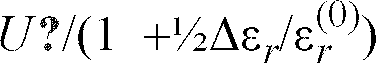
whereby the differential pressure range and resolution can be adjusted through controlling the pulse amplitude (circuit 23).
The center point of the differential pressure range can be adjusted by adjusting the offset of the integrator of the Σ/Δ converter 9.
The pulse train signal is formed by means of a switch 17 controlled by thecircuit 9. - The method according to the invention may also be applied to the measurement of the dielectric coefficient. Further, by inserting a dielectric film responsive to, e.g., humidity, the capacitance change caused by the dielectric coefficient change can be utilized to measure the change of such an external variable.
- It is an object of the invention to keep the transducing diaphragm in a desired geometric shape irrespective of imposed differential pressure level or change in the dielectric coefficient. However, the above-described exemplifying embodiment achieving the desired goal by virtue of applying the feedback control signal to the two fixed
electrodes diaphragm 1 is not by any means the only solution according to the spirit of the invention. Alternatively, the desired charge balance viz. controlled deviation from the balance and corresponding balance of electrostatic forces in the measurement capacitors can be implemented using a desired even number of the fixed electrodes. Namely, an even number of fixed electrodes permits a relaxed selection of control voltage pulse train amplitudes provided that the charge and electrostatic force balance conditions discussed above are fulfilled. - In accordance with the above-described control arrangements, a term effective area may be defined for the fixed
electrodes 
Scientific papers:
Claims (13)
- A feedback-control method for an asymmetric capacitive differential pressure transducer in which method a pressure-transducing conducting diaphragm (1) forming a first, moving electrode of the transducer capacitances is kept in a force balance state by means of a pulse train signal applied to a fixed electrode (2,3), the method being characterised by- keeping the diaphragm (1) stationary in a geometrically constant state and applying a desired electric potential to said diaphragm (1),- applying said pulse train signal to at least two of said fixed electrodes (2,3), or alternatively, sets of fixed subelectrodes so that- the signals applied to said separate electrodes (2,3) or sets or subelectrodes are at opposite polarities with respect to the electric potential of the pressure-transducing diaphragm (1) for at least a portion of the measurement duration, and- the signals applied to said separate electrodes (2,3) or sets of subelectrodes are of equal amplitude at least for each pair of electrodes (2,3), and- the same pulse train signal being simultaneously used for both establishing the force balance and performing the capacitance measurement.
- A method as defined in claim 1, characterised in that the capacitance between the pressure-transducing electrode (1) and the fixed electrodes (2,3) or subelectrodes is measured in two cyclicaily alternating phases comprising- measuring the difference of two transducing capacitances (C₁ - C₂) in the first phase and- measuring the sum of two transducing capacitances (C₁ + C₂) in the second phase.
- A method as defined in claim 2, characterised in that the difference between said two transducing capacitances (C₁ - C₂) is kept constant by means of a feedback arrangement, whereby the geometrical state of the transducing diaphragm (1) of the transducer is kept unchanged and the sum of the two transducing capacitances (C₁ + C₂) can be used for computing changes in the dielectric coefficient of the transducer fill medium.
- A method as defined in claim 1,2 or 3, characterised in that the fixed electrodes (2,3) or subelectrodes are fed with signals (+V₀,-V₀) of opposite polarity with regard to the ground potential.
- A method as defined in any preceding claim, in which method the feedback arrangement utilizes a pulse-rate modulated signal, characterised in that the measured change of the dielectric coefficient of the transducer fill medium is compensated for by altering the pulse amplitude or pulse rate.
- A method as defined in any preceding claim, in which method the feedback arrangement utilizes a pulse-rate modulated signal, characterised in that the measured change of the dielectric coefficient is compensated for by altering the pulse amplitude or pulse rate.
- A method as defined in any preceding claim, in which method the feedback arrangement utilizes a pulse-rate modulated signal, characterised in that the measured change of the dielectric coefficient is compensated for by altering the pulse width or pulse rate.
- A method as defined in any preceding claim, characterised in that the pulse train signal is applied to the conducting transducing diaphragm (1) via a reference capacitor (11) with the help of a switch (12) so that the pulse train signal is taken to the two fixed electrodes (2,3) of the transducer at the same polarity, and to the reference capacitor (11), at an opposite polarity with regard to the electric potential of the transducing diaphragm (1) of the transducer.
- An apparatus for feedback-control of an asymmetric capacitive differential pressure transducer (1,2,3) by means of an electrically controlled force balance principle, said apparatus comprising- a pressure-transducing conducting diaphragm (1) forming a first electrode of a transducing capacitor to be measured- at least one fixed electrode (2,3) adapted to the vicinity of said pressure-transducing diaphragm (1) so as to act as the second electrode of the transducing capacitor to be measured.- capacitance measurement means (5) for determining the capacitance of the transducing capacitor to be measured, and- a feedback apparatus (9,4,22,19) suited for feedback-controlling the transducing capacitor with the help of an electric pulse train signal employed to implement the force balance principle,characterised in that- said fixed electrode (2,3) comprises at least two subelectrodes (2,3) located concentrically,- said feedback apparatus (9,4,22,19) includes a means (7) suited for generating at least two pulse train signals (+V₀,-V₀) of opposite polarity with regard to the electric potential of the pressure-transducing diaphragm (1), said pulse train signals being suited for feed to at least two of the fixed electrodes (2,3).
- An apparatus as defined in claim 9, characterised in that said feedback apparatus (9,4,22, 19) includes a switch means (13) suited for alternately switching at least one of the fixed electrodes (2) to respectively an inverted and a non-Inverted pulse train signal.
- An apparatus as defined in claim 9, characterised in that said apparatus includes, besides the transducing capacitances (C₁ - C₂), a reference capacitor (11) connected to the conducting transducing diaphragm (1) of the transducer and a switch (12) suited for switching the reference capacitor (11) on and off in the measurement circuit.
- An apparatus as defined in claim 9, 10, or 11, characterised in that said fixed electrodes (2,3) have substantially equal effective areas.
- An apparatus as defined in claim 9,10,11 or 12, characterised in that the capacitance Cref of the reference capacitor (11) and the sum capacitance (C₁ + C₂) formed between the transducer fixed electrodes (2,3) and the transducing diaphragm (1), respectively are substantially equal.
Applications Claiming Priority (2)
| Application Number | Priority Date | Filing Date | Title |
|---|---|---|---|
| FI934434A FI93580C (en) | 1993-10-08 | 1993-10-08 | Method and apparatus for feedback of an asymmetric pressure differential sensor |
| FI934434 | 1993-10-08 |
Publications (3)
| Publication Number | Publication Date |
|---|---|
| EP0647840A2 true EP0647840A2 (en) | 1995-04-12 |
| EP0647840A3 EP0647840A3 (en) | 1996-01-31 |
| EP0647840B1 EP0647840B1 (en) | 1999-06-16 |
Family
ID=8538733
Family Applications (1)
| Application Number | Title | Priority Date | Filing Date |
|---|---|---|---|
| EP94307077A Expired - Lifetime EP0647840B1 (en) | 1993-10-08 | 1994-09-28 | Method and apparatus for feedbackcontrol of an asymmetric differential pressure transducer |
Country Status (7)
| Country | Link |
|---|---|
| US (1) | US5641911A (en) |
| EP (1) | EP0647840B1 (en) |
| JP (1) | JP3339974B2 (en) |
| CA (1) | CA2133685C (en) |
| DE (1) | DE69419100T2 (en) |
| FI (1) | FI93580C (en) |
| NO (1) | NO308052B1 (en) |
Cited By (2)
| Publication number | Priority date | Publication date | Assignee | Title |
|---|---|---|---|---|
| EP0718604A2 (en) * | 1994-12-22 | 1996-06-26 | Vaisala Oy | A method of linearizing a flow velocity sensor and a linearized flow velocity measurement apparatus |
| FR2851368A1 (en) * | 2003-02-18 | 2004-08-20 | Agence Spatiale Europeenne | Electronic component for microwave frequency systems has micro-electro-mechanical trimming capacitor with control circuit to adjust capacitance as a function of the difference between measured and set values of capacitance |
Families Citing this family (25)
| Publication number | Priority date | Publication date | Assignee | Title |
|---|---|---|---|---|
| US5817943A (en) * | 1997-03-24 | 1998-10-06 | General Electric Company | Pressure sensors |
| FI105237B (en) * | 1998-06-24 | 2000-06-30 | Valtion Teknillinen | Silicon micro mechanical balance |
| JP4467027B2 (en) * | 2000-10-30 | 2010-05-26 | ミヤチシステムズ株式会社 | Electrical circuit disconnection inspection method |
| US20030098699A1 (en) * | 2001-11-16 | 2003-05-29 | Lemkin Mark A. | Sense interface system with velocity feed-through rejection |
| US20050224899A1 (en) * | 2002-02-06 | 2005-10-13 | Ramsey Craig C | Wireless substrate-like sensor |
| DE60306892T2 (en) * | 2003-05-02 | 2007-08-30 | Stmicroelectronics S.R.L., Agrate Brianza | Method and arrangement for measuring the coupling capacitance between two tracks |
| US6877382B1 (en) * | 2003-10-20 | 2005-04-12 | Robert D Gourlay | Inhalation detector |
| US7893697B2 (en) * | 2006-02-21 | 2011-02-22 | Cyberoptics Semiconductor, Inc. | Capacitive distance sensing in semiconductor processing tools |
| CN101410690B (en) * | 2006-02-21 | 2011-11-23 | 赛博光学半导体公司 | Capacitive distance sensing in semiconductor processing tools |
| WO2008042199A2 (en) | 2006-09-29 | 2008-04-10 | Cyberoptics Semiconductor, Inc. | Particles sensor integrated with substrate |
| TW200849444A (en) * | 2007-04-05 | 2008-12-16 | Cyberoptics Semiconductor Inc | Semiconductor processing system with integrated showerhead distance measuring device |
| US20090015268A1 (en) * | 2007-07-13 | 2009-01-15 | Gardner Delrae H | Device and method for compensating a capacitive sensor measurement for variations caused by environmental conditions in a semiconductor processing environment |
| DE102007062713A1 (en) * | 2007-12-27 | 2009-07-16 | Robert Bosch Gmbh | Pressure sensor and method for its calibration |
| EP2343507B1 (en) * | 2009-12-24 | 2012-11-28 | EM Microelectronic-Marin SA | Method of capacitively measuring a physical parameter and electronic circuit to interface with a capacitive sensor |
| US8656772B2 (en) | 2010-03-22 | 2014-02-25 | Honeywell International Inc. | Flow sensor with pressure output signal |
| US8616065B2 (en) * | 2010-11-24 | 2013-12-31 | Honeywell International Inc. | Pressure sensor |
| US8695417B2 (en) | 2011-01-31 | 2014-04-15 | Honeywell International Inc. | Flow sensor with enhanced flow range capability |
| TWI447402B (en) * | 2012-03-05 | 2014-08-01 | Mstar Semiconductor Inc | Device for detecting capacitance and capacitive-type touch control system utilizing the same |
| US9052217B2 (en) | 2012-11-09 | 2015-06-09 | Honeywell International Inc. | Variable scale sensor |
| US10309997B2 (en) * | 2013-03-15 | 2019-06-04 | Infineon Technologies Ag | Apparatus and a method for generating a sensor signal indicating information on a capacitance of a variable capacitor comprising a variable capacitance |
| US8960010B1 (en) | 2013-12-23 | 2015-02-24 | Fresenius Medical Care Holdings, Inc. | Automatic detection and adjustment of a pressure pod diaphragm |
| DE102014201529A1 (en) * | 2014-01-28 | 2015-07-30 | Siemens Aktiengesellschaft | Method for operating a pressure transmitter and pressure transmitter |
| US9645029B2 (en) | 2014-04-07 | 2017-05-09 | Infineon Technology Ag | Force feedback loop for pressure sensors |
| CN106573095B (en) * | 2014-09-26 | 2020-06-26 | 费森尤斯医疗保健集团 | Pressure output device for extracorporeal hemodialysis machine |
| WO2020159603A2 (en) * | 2018-11-19 | 2020-08-06 | Aurigema Andrew Neil | System and method for generating forces using asymmetrical electrostatic pressure |
Citations (4)
| Publication number | Priority date | Publication date | Assignee | Title |
|---|---|---|---|---|
| US3952234A (en) * | 1973-12-31 | 1976-04-20 | Donald Jack Birchall | Pressure transducers |
| US4584885A (en) * | 1984-01-20 | 1986-04-29 | Harry E. Aine | Capacitive detector for transducers |
| EP0323709A2 (en) * | 1987-12-04 | 1989-07-12 | Michael King Russell | Tri-axial accelerometers |
| US5211051A (en) * | 1987-11-09 | 1993-05-18 | California Institute Of Technology | Methods and apparatus for improving sensor performance |
Family Cites Families (5)
| Publication number | Priority date | Publication date | Assignee | Title |
|---|---|---|---|---|
| US4434664A (en) * | 1981-07-06 | 1984-03-06 | The Bendix Corporation | Pressure ratio measurement system |
| FI872049A (en) * | 1987-05-08 | 1988-11-09 | Vaisala Oy | KONDENSATORKONSTRUKTION FOER ANVAENDNING VID TRYCKGIVARE. |
| JPH0672899B2 (en) * | 1988-04-01 | 1994-09-14 | 株式会社日立製作所 | Acceleration sensor |
| US5377524A (en) * | 1992-06-22 | 1995-01-03 | The Regents Of The University Of Michigan | Self-testing capacitive pressure transducer and method |
| FI93579C (en) * | 1993-08-20 | 1995-04-25 | Vaisala Oy | Capacitive encoder feedback with electrostatic force and method for controlling the shape of its active element |
-
1993
- 1993-10-08 FI FI934434A patent/FI93580C/en active
-
1994
- 1994-09-28 EP EP94307077A patent/EP0647840B1/en not_active Expired - Lifetime
- 1994-09-28 DE DE69419100T patent/DE69419100T2/en not_active Expired - Lifetime
- 1994-10-04 US US08/317,358 patent/US5641911A/en not_active Expired - Lifetime
- 1994-10-05 CA CA002133685A patent/CA2133685C/en not_active Expired - Fee Related
- 1994-10-07 NO NO943787A patent/NO308052B1/en not_active IP Right Cessation
- 1994-10-07 JP JP24387094A patent/JP3339974B2/en not_active Expired - Fee Related
Patent Citations (4)
| Publication number | Priority date | Publication date | Assignee | Title |
|---|---|---|---|---|
| US3952234A (en) * | 1973-12-31 | 1976-04-20 | Donald Jack Birchall | Pressure transducers |
| US4584885A (en) * | 1984-01-20 | 1986-04-29 | Harry E. Aine | Capacitive detector for transducers |
| US5211051A (en) * | 1987-11-09 | 1993-05-18 | California Institute Of Technology | Methods and apparatus for improving sensor performance |
| EP0323709A2 (en) * | 1987-12-04 | 1989-07-12 | Michael King Russell | Tri-axial accelerometers |
Cited By (6)
| Publication number | Priority date | Publication date | Assignee | Title |
|---|---|---|---|---|
| EP0718604A2 (en) * | 1994-12-22 | 1996-06-26 | Vaisala Oy | A method of linearizing a flow velocity sensor and a linearized flow velocity measurement apparatus |
| EP0718604A3 (en) * | 1994-12-22 | 1998-05-20 | Vaisala Oy | A method of linearizing a flow velocity sensor and a linearized flow velocity measurement apparatus |
| FR2851368A1 (en) * | 2003-02-18 | 2004-08-20 | Agence Spatiale Europeenne | Electronic component for microwave frequency systems has micro-electro-mechanical trimming capacitor with control circuit to adjust capacitance as a function of the difference between measured and set values of capacitance |
| WO2004075247A2 (en) * | 2003-02-18 | 2004-09-02 | Agency Spatiale Europeenne | Electronic components comprising adjustable-capacitance micro-electro-mechanical capacitors |
| WO2004075247A3 (en) * | 2003-02-18 | 2004-09-30 | Agency Spatiale Europ | Electronic components comprising adjustable-capacitance micro-electro-mechanical capacitors |
| US7495882B2 (en) | 2003-02-18 | 2009-02-24 | Agence Spatiale Europeenne | Electronic components comprising adjustable-capacitance micro-electro-mechanical capacitors |
Also Published As
| Publication number | Publication date |
|---|---|
| JP3339974B2 (en) | 2002-10-28 |
| CA2133685A1 (en) | 1995-04-09 |
| NO943787D0 (en) | 1994-10-07 |
| EP0647840A3 (en) | 1996-01-31 |
| US5641911A (en) | 1997-06-24 |
| FI93580B (en) | 1995-01-13 |
| FI93580C (en) | 1995-04-25 |
| DE69419100D1 (en) | 1999-07-22 |
| NO943787L (en) | 1995-04-10 |
| EP0647840B1 (en) | 1999-06-16 |
| CA2133685C (en) | 2006-08-15 |
| JPH07181094A (en) | 1995-07-18 |
| DE69419100T2 (en) | 2000-03-30 |
| NO308052B1 (en) | 2000-07-10 |
| FI934434A0 (en) | 1993-10-08 |
Similar Documents
| Publication | Publication Date | Title |
|---|---|---|
| EP0647840B1 (en) | Method and apparatus for feedbackcontrol of an asymmetric differential pressure transducer | |
| US4584885A (en) | Capacitive detector for transducers | |
| JP3264884B2 (en) | Capacitance detection circuit | |
| JP2936286B2 (en) | Precision capacitive transducer circuit and method | |
| US5597956A (en) | Capacitor type acceleration sensor | |
| US6933873B1 (en) | PWM-based measurement interface for a micro-machined electrostatic actuator | |
| US5977803A (en) | Capacitance type sensor interface circuit | |
| JPH06265417A (en) | Force-measuring device | |
| US5095750A (en) | Accelerometer with pulse width modulation | |
| US5194819A (en) | Linearized capacitance sensor system | |
| US5473946A (en) | Accelerometer using pulse-on-demand control | |
| JP4902552B2 (en) | Capacitance detection device | |
| KR100382766B1 (en) | Apparatus and method for measuring change of capacitance | |
| US5528520A (en) | Calibration circuit for capacitive sensors | |
| Mochizuki et al. | A high-accuracy high-speed signal processing circuit of differential-capacitance transducers | |
| US5019783A (en) | Precision transducer circuit and linearization method | |
| JPH0623781B2 (en) | Acceleration detection method and device | |
| US20080079435A1 (en) | Electrostatic Voltmeter With Spacing-Independent Speed of Response | |
| JP3282360B2 (en) | Capacitive sensor | |
| JPH11201850A (en) | Electrostatic servo type physical amount detector | |
| JP3322726B2 (en) | Capacitance detection circuit | |
| JP2000221054A (en) | Capacitive physical quantity detector | |
| JPH07260510A (en) | Capacity type sensor | |
| JP3265807B2 (en) | Capacitive sensor | |
| RU2107301C1 (en) | Compensation accelerometer |
Legal Events
| Date | Code | Title | Description |
|---|---|---|---|
| PUAI | Public reference made under article 153(3) epc to a published international application that has entered the european phase |
Free format text: ORIGINAL CODE: 0009012 |
|
| AK | Designated contracting states |
Kind code of ref document: A2 Designated state(s): CH DE DK FR GB LI NL SE |
|
| PUAL | Search report despatched |
Free format text: ORIGINAL CODE: 0009013 |
|
| AK | Designated contracting states |
Kind code of ref document: A3 Designated state(s): CH DE DK FR GB LI NL SE |
|
| 17P | Request for examination filed |
Effective date: 19960313 |
|
| 17Q | First examination report despatched |
Effective date: 19970418 |
|
| GRAG | Despatch of communication of intention to grant |
Free format text: ORIGINAL CODE: EPIDOS AGRA |
|
| GRAG | Despatch of communication of intention to grant |
Free format text: ORIGINAL CODE: EPIDOS AGRA |
|
| GRAH | Despatch of communication of intention to grant a patent |
Free format text: ORIGINAL CODE: EPIDOS IGRA |
|
| RAP1 | Party data changed (applicant data changed or rights of an application transferred) |
Owner name: VAISALA OYJ |
|
| GRAH | Despatch of communication of intention to grant a patent |
Free format text: ORIGINAL CODE: EPIDOS IGRA |
|
| GRAA | (expected) grant |
Free format text: ORIGINAL CODE: 0009210 |
|
| AK | Designated contracting states |
Kind code of ref document: B1 Designated state(s): CH DE DK FR GB LI NL SE |
|
| PG25 | Lapsed in a contracting state [announced via postgrant information from national office to epo] |
Ref country code: SE Free format text: THE PATENT HAS BEEN ANNULLED BY A DECISION OF A NATIONAL AUTHORITY Effective date: 19990616 Ref country code: NL Free format text: LAPSE BECAUSE OF FAILURE TO SUBMIT A TRANSLATION OF THE DESCRIPTION OR TO PAY THE FEE WITHIN THE PRESCRIBED TIME-LIMIT Effective date: 19990616 Ref country code: LI Free format text: LAPSE BECAUSE OF FAILURE TO SUBMIT A TRANSLATION OF THE DESCRIPTION OR TO PAY THE FEE WITHIN THE PRESCRIBED TIME-LIMIT Effective date: 19990616 Ref country code: CH Free format text: LAPSE BECAUSE OF FAILURE TO SUBMIT A TRANSLATION OF THE DESCRIPTION OR TO PAY THE FEE WITHIN THE PRESCRIBED TIME-LIMIT Effective date: 19990616 |
|
| REG | Reference to a national code |
Ref country code: CH Ref legal event code: EP |
|
| REF | Corresponds to: |
Ref document number: 69419100 Country of ref document: DE Date of ref document: 19990722 |
|
| ET | Fr: translation filed | ||
| PG25 | Lapsed in a contracting state [announced via postgrant information from national office to epo] |
Ref country code: DK Free format text: LAPSE BECAUSE OF FAILURE TO SUBMIT A TRANSLATION OF THE DESCRIPTION OR TO PAY THE FEE WITHIN THE PRESCRIBED TIME-LIMIT Effective date: 19990916 |
|
| NLV1 | Nl: lapsed or annulled due to failure to fulfill the requirements of art. 29p and 29m of the patents act | ||
| REG | Reference to a national code |
Ref country code: CH Ref legal event code: PL |
|
| PLBE | No opposition filed within time limit |
Free format text: ORIGINAL CODE: 0009261 |
|
| STAA | Information on the status of an ep patent application or granted ep patent |
Free format text: STATUS: NO OPPOSITION FILED WITHIN TIME LIMIT |
|
| 26N | No opposition filed | ||
| REG | Reference to a national code |
Ref country code: GB Ref legal event code: IF02 |
|
| PGFP | Annual fee paid to national office [announced via postgrant information from national office to epo] |
Ref country code: GB Payment date: 20090922 Year of fee payment: 16 |
|
| PGFP | Annual fee paid to national office [announced via postgrant information from national office to epo] |
Ref country code: DE Payment date: 20090922 Year of fee payment: 16 |
|
| GBPC | Gb: european patent ceased through non-payment of renewal fee |
Effective date: 20100928 |
|
| REG | Reference to a national code |
Ref country code: FR Ref legal event code: ST Effective date: 20110531 |
|
| REG | Reference to a national code |
Ref country code: DE Ref legal event code: R119 Ref document number: 69419100 Country of ref document: DE Effective date: 20110401 |
|
| PG25 | Lapsed in a contracting state [announced via postgrant information from national office to epo] |
Ref country code: FR Free format text: LAPSE BECAUSE OF NON-PAYMENT OF DUE FEES Effective date: 20100930 Ref country code: DE Free format text: LAPSE BECAUSE OF NON-PAYMENT OF DUE FEES Effective date: 20110401 |
|
| PG25 | Lapsed in a contracting state [announced via postgrant information from national office to epo] |
Ref country code: GB Free format text: LAPSE BECAUSE OF NON-PAYMENT OF DUE FEES Effective date: 20100928 |
|
| PGFP | Annual fee paid to national office [announced via postgrant information from national office to epo] |
Ref country code: FR Payment date: 20091001 Year of fee payment: 16 |