EP0651861B1 - Method and apparatus for engaging threaded members - Google Patents
Method and apparatus for engaging threaded members Download PDFInfo
- Publication number
- EP0651861B1 EP0651861B1 EP94914138A EP94914138A EP0651861B1 EP 0651861 B1 EP0651861 B1 EP 0651861B1 EP 94914138 A EP94914138 A EP 94914138A EP 94914138 A EP94914138 A EP 94914138A EP 0651861 B1 EP0651861 B1 EP 0651861B1
- Authority
- EP
- European Patent Office
- Prior art keywords
- threaded elements
- elements
- threads
- coupling
- frustoconical
- Prior art date
- Legal status (The legal status is an assumption and is not a legal conclusion. Google has not performed a legal analysis and makes no representation as to the accuracy of the status listed.)
- Expired - Lifetime
Links
- 238000000034 method Methods 0.000 title claims description 4
- 230000008878 coupling Effects 0.000 claims abstract description 67
- 238000010168 coupling process Methods 0.000 claims abstract description 67
- 238000005859 coupling reaction Methods 0.000 claims abstract description 67
- 238000003780 insertion Methods 0.000 claims description 3
- 230000037431 insertion Effects 0.000 claims description 3
- 230000013011 mating Effects 0.000 claims 1
- 230000001154 acute effect Effects 0.000 description 6
- 230000000295 complement effect Effects 0.000 description 1
- 238000010586 diagram Methods 0.000 description 1
- 230000000694 effects Effects 0.000 description 1
- 230000005484 gravity Effects 0.000 description 1
- 239000002184 metal Substances 0.000 description 1
Images


Classifications
-
- F—MECHANICAL ENGINEERING; LIGHTING; HEATING; WEAPONS; BLASTING
- F16—ENGINEERING ELEMENTS AND UNITS; GENERAL MEASURES FOR PRODUCING AND MAINTAINING EFFECTIVE FUNCTIONING OF MACHINES OR INSTALLATIONS; THERMAL INSULATION IN GENERAL
- F16B—DEVICES FOR FASTENING OR SECURING CONSTRUCTIONAL ELEMENTS OR MACHINE PARTS TOGETHER, e.g. NAILS, BOLTS, CIRCLIPS, CLAMPS, CLIPS OR WEDGES; JOINTS OR JOINTING
- F16B37/00—Nuts or like thread-engaging members
- F16B37/08—Quickly-detachable or mountable nuts, e.g. consisting of two or more parts; Nuts movable along the bolt after tilting the nut
- F16B37/0807—Nuts engaged from the end of the bolt, e.g. axially slidable nuts
- F16B37/0857—Nuts engaged from the end of the bolt, e.g. axially slidable nuts with the threaded portions of the nut engaging the thread of the bolt by the action of one or more springs or resilient retaining members
-
- Y—GENERAL TAGGING OF NEW TECHNOLOGICAL DEVELOPMENTS; GENERAL TAGGING OF CROSS-SECTIONAL TECHNOLOGIES SPANNING OVER SEVERAL SECTIONS OF THE IPC; TECHNICAL SUBJECTS COVERED BY FORMER USPC CROSS-REFERENCE ART COLLECTIONS [XRACs] AND DIGESTS
- Y10—TECHNICAL SUBJECTS COVERED BY FORMER USPC
- Y10T—TECHNICAL SUBJECTS COVERED BY FORMER US CLASSIFICATION
- Y10T29/00—Metal working
- Y10T29/49—Method of mechanical manufacture
- Y10T29/49826—Assembling or joining
- Y10T29/49947—Assembling or joining by applying separate fastener
- Y10T29/49948—Multipart cooperating fastener [e.g., bolt and nut]
Definitions
- the present invention relates to a coupling device featuring threaded members capable of rapid engagement and disengagement.
- Threaded coupling devices such as conventional nuts and bolts, have often proven ineffective in highly specialized applications, for example, where speed is required, or where extended rotating movement is undesirable.
- Efforts have been made to design threaded coupling devices which may be assembled by rapid rectilinear movement followed by final tightening by rotating one member relative to the other. Just as there is a need to reduce the time and effort required to assemble threaded coupling members, there also exists a need to simplify and speed up the process of disengaging threaded coupling devices.
- US-A-4083393 describes a nut having a series of segments in a tapered hole in a base part for sliding movement upwardly and downwardly to allow insertion of a bolt.
- Each segment Includes a guide pin and an operation ring is provided including can sections, each of the latter comprising a lower flat surface, an upper flat surface and an inclined surface connecting said upper flat surface with said lower flat surface, said lower and upper flat surfaces extending substantially parallel to the bearing end face of said base part, said cam sections engage said guide pins of said individual nut segments, respectively, to control said nut segments, whereby said nut segments are slidable upwardly on said inner surface of said tapered hole by rotation of said operation ring as well as by lifting of said nut segments and said guide pins therewith off said cam sections, respectively.
- a coupling device comprising:
- the coupling device of the present invention includes a first member provided with external threads and a second member having an opening therein into which the first member is inserted.
- the second member is provided with pluralities of movably mounted internally threaded elements for receiving the external threads of the first member. Structure is provided whereby the first member may be inserted within the second member by rectilinear sliding movement for a predetermined distance after which the first member may be rotated into tight engagement with the second member. Release of the first member may be accomplished simply by rotating the first member very slightly in the opposite direction, after which simple manual manipulation of the second member withdraws the threaded elements from engagement permitting the first member to be slidably removed axially from the second member. With the present invention it is therefore possible to attach and detach threaded couplings quickly with only minimal rotating action.
- the coupling device of the present invention includes a first member 10 provided with threads and a second member 12 having a threaded opening therein into which the first member 10 may be inserted in locking relationship.
- the first member 10 in the preferred embodiment is a bolt provided with a head 14 and helical threads 16 on the shaft thereof.
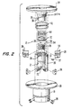
- the second member 12 will now be described with reference to Figs. 2, 3 and 6.
- the second member 12 includes a sleeve 18 into which is slidably mounted a cylinder 20.
- the cylinder 20 is provided with a series of slots 22 through which corresponding keys 24 pass.
- the keys 24 are attached to the sleeve 18 with fasteners 26.
- the cylinder 20 is provided with a frustoconical surface 19, as best seen in Fig. 3. More particularly, the frustoconical surface 19 is a surface of revolution extending at an acute angle ⁇ to the longitudinal axis of the sleeve 18 and cylinder 20 along which the first member 10 moves. A second frustoconical surface 21 is provided within the cylinder 20 extending at an acute angle ⁇ to the longitudinal axis of the sleeve 18 and the cylinder 20.
- a plurality of movably mounted, externally threaded elements generally designated by the reference numeral 28 are positioned within the lower cavity of the cylinder 20.
- the movably mounted threaded elements 28, which in the preferred embodiment are three in number, are held in place and urged downwardly within the cavity 30 by the washer 32, as explained hereinafter.
- the movably mounted threaded elements 28 are provided with internal threads 29 coaxial with the cylinder 20.
- the internal threads 29 have an apex angle ⁇ .
- the second member 12 includes a cap 34 which is mounted for movement relative to the sleeve 18.
- the cap 34 includes a shoulder 36 provided with threads 38 which engage threads 39 of the cylinder 20 permitting the cap 34 to be screwed in place within the cylinder 20.
- a hole 35A is provided in the shoulder 36 for receiving a locking pin 37 which passes through the hole 21A in the cylinder 20.
- a coil spring 40 is positioned within the gap 42 between the outer wall of the cap 34 and the inner wall of the sleeve 18. The coil spring 40 normally urges the cap 34 and the sleeve 18 in opposite directions.
- a second coil spring 44 is positioned within the cavity 46 between the shoulder 48 of the cap 34 and the lip 50 of the washer 32.
- the second coil spring 44 normally urges the washer 32 downwardly such that the lip 50 thereof engages the upper edges 54 of the movably mounted threaded elements 28, as seen in Fig. 5.
- each of the movably mounted internally threaded elements 28 is depicted in Figs. 3, 5 and 6.
- Each threaded element 28 includes at the top on the inner surface thereof a frustoconical surface 52 terminating at the upper portion thereof in the edge 54 against which the bottom of the lip 50 of the washer 32 abuts.
- Each of the elements 28 is also provided with a frustoconical surface 55 extending at an acute angle ⁇ to the axis of the sleeve 18, thus permitting easy sliding movement between the frustoconical surfaces 21 and 55.
- each of the movably mounted internally threaded elements 28 is provided near the bottom thereof with a frustoconical surface 56 which extends at an acute angle ⁇ to the axis of the cylinder 20.
- the frustoconical surfaces 56 of the movably mounted threaded elements 28 are thereby adapted to axially abut and slide on the frustoconical surface 19 of the cylinder 20.
- each of the elements 28 abuts the sloping surface 58 of each of the keys 24.
- the acute angle ⁇ (Fig. 3) of the aforementioned frustoconical surfaces is less than the apex angle ⁇ of the threads 29 of the elements 28.
- the inclined surfaces of the threads 29 extend at greater acute angles to the axis of the cylinder 20, then the frustoconical surfaces of the cylinder 20.
- each of the keys 24 protrudes through a slot 22 formed in the cylinder 20 and engages the sloping surface 56A of the movably mounted threaded element 28.
- each of the threaded elements 28 is provided with a notch 57 defining the downwardly sloping contact surface area 56A which is complementary in configuration with respect to the downwardly sloping contact surface 58 of the key 24.
- Fig. 6 illustrates the position of the movably mounted, internally threaded elements 28 before the first member or bolt 10 is inserted within the second member 12. It will be apparent that the groups of threaded elements 28 are urged inwardly towards each other in an axial direction by the force of the second spring 44.
- Fig. 7 illustrates the position of the parts when the first member or bolt 10 is moved into the second member 12 by sliding movement, i.e., the bolt 10 is moved inwardly merely by pushing it without rotation. It will be apparent that as the threads 16 of the first member 10 engage the threads 29 of each of the threaded elements 28, the elements 28 are moved radially outward. With reference to the schematic of Fig.
- Fig. 8 illustrates the first member or bolt 10 fully inserted within the second member 12.
- the head 14 is manually rotated until the inside surface 61 of the head 14 abuts the lower surface 62 of the sleeve 18, thus locking the first member 10 within the second member 12.
- the threaded elements 28 are movably mounted within the cylinder 20, there is some capability of movement even when the bolt 10 is being inserted within the elements 28.
- the frictional force between the threads 16 and 29 is enhanced by the resiliency of the engagement between the threaded elements 28 and the threaded bolt 10.
- the threaded elements 28 are not rigidly positioned within the cylinder 20--as in the case of most fastening nuts--the tightening of the bolt 10 by rotation tends to resiliently urge the threaded elements 28 downwardly providing an unusually tight locking action.
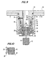
- Safety features are provided to guard against accidental unlocking.
- the cap 34 is continuous metal to base to guard against "bump release;" the shoulder 35 of the sleeve 18 must be pulled toward the cap 34 to effect release. Also, the shoulder 35 of the sleeve can not be moved toward the cap 34 until the tension between the threads is released.
- Fig. 9 illustrates releasing of the first member 10. More particularly, as the cap 34 and the shoulder 35 of the sleeve 18 are moved in close proximity to one another against the force of the first coil spring 40, the upward movement of the keys 24, and the sliding movement of the supporting surfaces 58 of the keys 24 and the supporting surfaces 56 of the threaded elements 28 promoted thereby, move the threaded elements 28 outwardly away from each other in a radial direction, thus releasing the engagement between the threads 16 of the first member 10 and the threads 29 of the threaded elements 28, thus permitting the first member 10 to be removed by rectilinear, sliding movement. It is to be noted, returning to Fig. 8, that the first member or bolt 10 is locked securely in place by rotation, as previously described.
Abstract
Description
Claims (9)
- A coupling device comprising:a first member (10) provided with threads (16);a second member (12) having an opening therein lying along a longitudinal axis into and out of which said first member (10) may be inserted and removed;said second member (12) including a first frustoconical surface (19) and a second frustoconical surface (21) spaced from said first frustoconical surface (19);a plurality of threaded elements (28) each having internal threads (29) a first frustoconical bearing surface (56) for sliding movement with respect to said first frustoconical surface (19) on said second member and a second frustoconical bearing surface (55) for sliding movement with respect to said second frustoconical surface (21) on said second membermeans (32,34) mounting said threaded elements for movement outwardly with respect to the longitudinal axis of said second member (12)means normally urging said threaded elements inwardly with respect to the longitudinal axis of the second member (12) whereby the inward sliding movement of said first member (10) within said opening of said second member (12) along said longitudinal axis causes said threaded elements (28) to move radially outward by sliding action along said first and second frustoconical surfaces of said second member and said first and second bearing surfaces of said threaded elements after which brief rotating movement of said first member (10) tightly moves said first member (10) into engagement with said second member (12); andmeans (24,58) moving said threaded elements (28) radially outward by sliding cooperation between said first and second frustoconical surfaces (19,21) and said first and second frustoconical bearing surfaces (55,56) thereby permitting said first member (10) to be moved outwardly along said axis by sliding movement.
- A coupling device as claimed in claim 1, wherein said threaded elements (28) comprise a plurality of internally threaded elements having frustoconical surfaces (52,55,56) mating with corresponding frustoconical surfaces (52A,21,19) within the second member (12) thus permitting said threaded elements (28) to move inwardly and outwardly in a radial direction relative to the second member (12) and means biasing said threaded elements (28) inwardly within said second member (12).
- A coupling device as claimed in claim 1 or 2, wherein said means moving said threaded elements (28) radially outward comprises a movably mounted key element (24) associated with each of said threaded elements (28) and provided with a sloping supporting surface (58), each of said threaded elements (28) having a corresponding sloping supporting surface (56A), such that movement of said key elements (24) causes sliding movement of said threaded elements (28) along the juncture of said sloping supporting surfaces (58,56A) moving said internally threaded elements (28) outwardly.
- A coupling device as claimed in claim 3, wherein said means moving said threaded elements (28) outwardly further comprises a cap (34) associated with said second member (12), means (40) biasing said cap (34) away from said second member (12), said threaded elements (28) being movable with said cap (34) wherein said key elements (24) move with said second member (12), such that movement of said cap (34) and said second member (28) towards each other against the force of said biasing means (40) causes the aforementioned movement of said key elements (24).
- A coupling device as claimed in claim 1 or 2, wherein said second member (12) comprises a cylinder (20) provided with a plurality of slots (22) therein, a plurality of threaded elements (28), means mounting said elements to move between a first inner position wherein the threads (29) are positioned to mate with the threads (16) of said first member (10) and a second, outer position wherein the threads (29) are out of engagement with the threads (16) of said first member (10), means urging said threaded elements (28) to said first, inner position, slotted portions (57) within said threaded elements including inclined supporting surfaces (56A), and wherein said means moving said threaded elements (28) outwardly permitting said first member (10) to move outwardly along said axis by sliding movement comprises key elements (24) extending through said slots (22) of said cylinder including sloping supporting surfaces (58) engaging the supporting surfaces (56A) of said threaded elements (28) and means moving said keys (24) upwardly causing said threaded elements (28) to move outwardly towards said second position as there is sliding movement between the supporting surfaces (58,56A) of the keys (24) and the threaded elements (28).
- A coupling device as claimed in claim 5, wherein said means moving said key elements (24) comprises a sleeve (18), said key elements (24) secured to said sleeve (18), a cap (34) connected to said cylinder (20), spring means (40) urging said cap (34) and sleeve (18) away from each other, such that manual movement of said cap (34) and sleeve (18) towards each other moves said key elements (24), the sliding action between said supporting surfaces (58,56A) of said key elements (24) and the threaded elements (28) moving said threaded elements (28) to their second outer position.
- A coupling device as claimed in any one of the preceding claims, wherein said first and second frustoconical surfaces (19,21) on said second member (12) and said first and second frustoconical bearing surfaces (56,55) on said threaded elements (28) each extend at the same angle with respect to the longitudinal axis of the second member (12).
- A coupling device as claimed in any one of the preceding claims, in which said brief rotating movement of said first member (10) causes the frictional force between said threads (16,29) to be enhanced because of the resiliency of the engagement between said threads (16) of the first member (10) and said threads (29) of said threaded elements (28).
- A method of rapidly engaging and disengaging first and second coupling members (10,12) provided with external and internal threads (16,29), respectively, comprising the steps of:inserting the first coupling member within the second coupling member;insertion of the first member causing the internal threads (29) of the second coupling member, which threads on a plurality of threaded elements (28) forming part of said second coupling member (12), to move apart from each other by sliding action along first and second spaced frustoconical surfaces (19,21) of said second member and first and second frustoconical bearing surfaces (56,55) of said threaded elements (28);continuing to move the first coupling member (10) within the second coupling member (12) by sliding movement;briefly rotating the first coupling member (10) such that the external threads thereof tightly engage the internal threads of the second coupling member (12) locking the coupling members (10,12) together;rotating the first coupling member (10) in the opposite direction to release the tight engagement between the external threads of the first coupling member (10) and the internal threads of the second coupling member (12);moving the internal threads of the second coupling member (12) apart from each other; andremoving the first coupling member (10) from the second coupling member (12) by sliding movement.
Applications Claiming Priority (3)
| Application Number | Priority Date | Filing Date | Title |
|---|---|---|---|
| US47199 | 1993-04-16 | ||
| US08/047,199 US5378100A (en) | 1993-04-16 | 1993-04-16 | Method and apparatus for rapidly engaging and disengaging threaded coupling members |
| PCT/US1994/004024 WO1994024442A1 (en) | 1993-04-16 | 1994-04-12 | Method and apparatus for engaging threaded members |
Publications (3)
| Publication Number | Publication Date |
|---|---|
| EP0651861A1 EP0651861A1 (en) | 1995-05-10 |
| EP0651861A4 EP0651861A4 (en) | 1995-05-24 |
| EP0651861B1 true EP0651861B1 (en) | 1998-07-29 |
Family
ID=21947608
Family Applications (1)
| Application Number | Title | Priority Date | Filing Date |
|---|---|---|---|
| EP94914138A Expired - Lifetime EP0651861B1 (en) | 1993-04-16 | 1994-04-12 | Method and apparatus for engaging threaded members |
Country Status (11)
| Country | Link |
|---|---|
| US (3) | US5378100A (en) |
| EP (1) | EP0651861B1 (en) |
| JP (1) | JP3108100B2 (en) |
| CN (1) | CN1104835A (en) |
| AT (1) | ATE169093T1 (en) |
| BR (1) | BR9405138A (en) |
| DE (1) | DE69412034T2 (en) |
| ES (1) | ES2125451T3 (en) |
| RU (1) | RU2148734C1 (en) |
| TW (1) | TW247342B (en) |
| WO (1) | WO1994024442A1 (en) |
Families Citing this family (73)
| Publication number | Priority date | Publication date | Assignee | Title |
|---|---|---|---|---|
| US5378100A (en) * | 1993-04-16 | 1995-01-03 | Fullerton; Robert L. | Method and apparatus for rapidly engaging and disengaging threaded coupling members |
| GB9411313D0 (en) * | 1994-06-07 | 1994-07-27 | Hedley Purvis Ltd | Improved reaction nut |
| US5603595A (en) * | 1995-04-12 | 1997-02-18 | Martin Marietta Corp. | Flywheel nut separable connector and method |
| US5613816A (en) * | 1995-06-09 | 1997-03-25 | Thread Technology, Inc. | Apparatus for rapidly engaging and disengaging threaded coupling members |
| US5695306A (en) * | 1996-05-08 | 1997-12-09 | Lockheed Martin Corp. | Fusible member connection apparatus and method |
| US5732989A (en) * | 1996-06-14 | 1998-03-31 | Transgaurd Industries, Inc. | Lock and tool therefor |
| US5800108A (en) | 1996-10-09 | 1998-09-01 | Thread Technology, Inc. | Apparatus for rapidly engaging and disengaging threaded coupling members |
| US5788443A (en) | 1997-03-13 | 1998-08-04 | Thread Technology, Inc. | Male coupling with movable threaded segments |
| US6033169A (en) * | 1998-12-29 | 2000-03-07 | Bettger; David D. | Axial-on threaded coupling device |
| US6450064B1 (en) * | 1999-05-20 | 2002-09-17 | Starsys Research Corporation | Resettable separation mechanism with anti-friction bearings |
| US6406240B1 (en) | 2000-03-09 | 2002-06-18 | Richard M. Potter | Fast acting nut assembly or coupling |
| US6684671B2 (en) * | 2000-11-02 | 2004-02-03 | Best Lock Corporation | Vending machine lock |
| US6361260B1 (en) | 2000-11-03 | 2002-03-26 | Wendell E. Schirrmacher | Quick locking fastener |
| US6425607B1 (en) | 2001-03-09 | 2002-07-30 | R. Potter Consulting, Inc. | Connector for pipe sections |
| US6478334B1 (en) | 2001-08-09 | 2002-11-12 | Breed Automotive Technology, Inc. | Energy-absorbing anchor, D-ring, turning loop or web guide |
| US7658582B2 (en) * | 2003-07-09 | 2010-02-09 | Ortho Innovations, Llc | Precise linear fastener system and method for use |
| WO2003106879A1 (en) * | 2002-06-14 | 2003-12-24 | Eaton Corporation | Coupling assembly |
| US7823936B2 (en) * | 2003-09-11 | 2010-11-02 | Stanley Security Solutions, Inc. | Vending machine lock |
| JP4403787B2 (en) * | 2003-12-01 | 2010-01-27 | 日本発條株式会社 | Simple fastening device |
| US20050158145A1 (en) * | 2004-01-16 | 2005-07-21 | Junkers John K. | Washer, fastener provided with a washer, method of and power tool for fastening objects |
| ES2582187T3 (en) * | 2004-12-17 | 2016-09-09 | Steelcase Inc. | Height adjustable table |
| DE102004061087B4 (en) * | 2004-12-18 | 2006-12-07 | A. Raymond Et Cie | Device for attaching an attachment and a support member at a distance from each other |
| US7198236B2 (en) * | 2004-12-20 | 2007-04-03 | Warner Terry P | Multi-sectional nut and adjustable length pole incorporating such nut |
| US7752824B2 (en) * | 2005-03-14 | 2010-07-13 | Mitek Holdings, Inc. | Shrinkage-compensating continuity system |
| US7416375B2 (en) * | 2005-07-26 | 2008-08-26 | Perigee Design Incorporated | Threaded coupling mechanism having quick engaging and disengaging feature |
| WO2007037009A1 (en) * | 2005-09-29 | 2007-04-05 | Kaoru Taneichi | Nut |
| US7762279B2 (en) | 2005-11-05 | 2010-07-27 | Snap-Tite Technologies, Inc. | Threaded coupling with flow shutoff |
| US7575024B2 (en) * | 2005-11-05 | 2009-08-18 | Snap-Tite Technologies, Inc. | Threaded coupling with flow shutoff |
| US7722302B2 (en) * | 2006-01-13 | 2010-05-25 | Oceaneering International, Inc. | Self locking tensioner |
| US8696280B2 (en) * | 2006-03-02 | 2014-04-15 | Spc International, Llc | Quick twist connector for marine battery |
| US8540471B2 (en) * | 2006-07-05 | 2013-09-24 | Visenut Llc | Quick attaching and detaching nut |
| US20080008556A1 (en) * | 2006-07-05 | 2008-01-10 | Steven Dvorak | Quick Attaching and Detaching Nut |
| US20080014049A1 (en) * | 2006-07-05 | 2008-01-17 | Steven Dvorak | Quick Attaching and Detaching Nut |
| WO2008094530A1 (en) * | 2007-01-30 | 2008-08-07 | Fullerton Fastening Systems Llc | Rapidly engaging female threaded coupler |
| US8167809B2 (en) | 2007-12-20 | 2012-05-01 | Silicon Valley Medical Instruments, Inc. | Imaging probe housing with fluid flushing |
| US20100021265A1 (en) * | 2008-07-24 | 2010-01-28 | Brent Parks | Separation fastener with frangible nut |
| US8142127B1 (en) * | 2008-10-28 | 2012-03-27 | United States Of America As Represented By The Secretary Of The Navy | Torque nut assembly |
| US8061945B2 (en) * | 2008-11-24 | 2011-11-22 | Zipnut Technology, Llc | Quick-acting threaded fastener |
| US9254123B2 (en) | 2009-04-29 | 2016-02-09 | Hansen Medical, Inc. | Flexible and steerable elongate instruments with shape control and support elements |
| US8342787B2 (en) * | 2009-11-11 | 2013-01-01 | Zipnut Technology, Llc | Fast-acting collapsible fastener |
| DE102010003017A1 (en) * | 2010-03-18 | 2011-09-22 | Peri Gmbh | Anchor nut and method for anchor setting and anchor release |
| US20120191107A1 (en) | 2010-09-17 | 2012-07-26 | Tanner Neal A | Systems and methods for positioning an elongate member inside a body |
| DE102011008057B4 (en) * | 2011-01-07 | 2013-05-29 | Haweka Ag | Quick-clamping nut, in particular for fastening a vehicle wheel on the clamping shaft of a balancing machine |
| US8646339B2 (en) * | 2011-02-07 | 2014-02-11 | Ronald A. Smith | Thread clamping device including internal sensing and reporting |
| US9138166B2 (en) | 2011-07-29 | 2015-09-22 | Hansen Medical, Inc. | Apparatus and methods for fiber integration and registration |
| EP2739864A4 (en) * | 2011-08-03 | 2015-04-08 | Qwikline Ind Products Inc | Split nut compression fastener system |
| US8881478B2 (en) | 2012-06-22 | 2014-11-11 | Simpson Strong-Tie Company, Inc. | Ratcheting take-up device |
| WO2014025760A2 (en) * | 2012-08-06 | 2014-02-13 | Espinosa Thomas M | Holder and concrete anchor assemblies |
| US10149720B2 (en) | 2013-03-08 | 2018-12-11 | Auris Health, Inc. | Method, apparatus, and a system for facilitating bending of an instrument in a surgical or medical robotic environment |
| US10376672B2 (en) | 2013-03-15 | 2019-08-13 | Auris Health, Inc. | Catheter insertion system and method of fabrication |
| US9394706B2 (en) | 2013-10-08 | 2016-07-19 | Simpson Strong-Tie Company, Inc. | Concrete anchor |
| US9763741B2 (en) | 2013-10-24 | 2017-09-19 | Auris Surgical Robotics, Inc. | System for robotic-assisted endolumenal surgery and related methods |
| US9163655B2 (en) | 2014-01-14 | 2015-10-20 | Kaoru Taneichi | Thrust nut |
| WO2015153718A1 (en) * | 2014-04-01 | 2015-10-08 | Erico International Corporation | Cylindrical object locking device and method |
| US9561083B2 (en) | 2014-07-01 | 2017-02-07 | Auris Surgical Robotics, Inc. | Articulating flexible endoscopic tool with roll capabilities |
| US9744335B2 (en) | 2014-07-01 | 2017-08-29 | Auris Surgical Robotics, Inc. | Apparatuses and methods for monitoring tendons of steerable catheters |
| US10792464B2 (en) | 2014-07-01 | 2020-10-06 | Auris Health, Inc. | Tool and method for using surgical endoscope with spiral lumens |
| US11819636B2 (en) | 2015-03-30 | 2023-11-21 | Auris Health, Inc. | Endoscope pull wire electrical circuit |
| US10463439B2 (en) | 2016-08-26 | 2019-11-05 | Auris Health, Inc. | Steerable catheter with shaft load distributions |
| EP3388699B1 (en) * | 2017-04-13 | 2021-09-01 | Black & Decker Inc. | Snap nut concrete anchor assembly |
| AU2018270785B2 (en) | 2017-05-17 | 2023-11-23 | Auris Health, Inc. | Exchangeable working channel |
| CN207229979U (en) * | 2017-08-31 | 2018-04-13 | 陈文繁 | A kind of quick coupling |
| US10927874B2 (en) * | 2018-03-16 | 2021-02-23 | Black & Decker Inc. | Snap nut concrete anchor assembly |
| EP4344723A2 (en) | 2018-03-28 | 2024-04-03 | Auris Health, Inc. | Medical instruments with variable bending stiffness profiles |
| EP3820373A4 (en) | 2018-08-07 | 2022-04-27 | Auris Health, Inc. | Combining strain-based shape sensing with catheter control |
| WO2020068853A2 (en) | 2018-09-26 | 2020-04-02 | Auris Health, Inc. | Articulating medical instruments |
| US11486466B2 (en) | 2019-01-15 | 2022-11-01 | Ulven Machinery Company, Inc. | Shackle with push to engage connector |
| US11617627B2 (en) | 2019-03-29 | 2023-04-04 | Auris Health, Inc. | Systems and methods for optical strain sensing in medical instruments |
| US11717147B2 (en) | 2019-08-15 | 2023-08-08 | Auris Health, Inc. | Medical device having multiple bending sections |
| EP3816463B1 (en) * | 2019-09-18 | 2023-02-15 | Nakaya Seisakusho Co., Ltd. | Nut |
| CN114901188A (en) | 2019-12-31 | 2022-08-12 | 奥瑞斯健康公司 | Dynamic pulley system |
| CN111075711B (en) * | 2020-01-03 | 2022-05-06 | 安徽华艺不锈钢容器有限公司 | Rotor pump convenient to maintain and use method thereof |
| CA3182562A1 (en) * | 2020-06-19 | 2021-12-23 | Jesse Benedict Rothschild | Attachment assembly and method |
Family Cites Families (20)
| Publication number | Priority date | Publication date | Assignee | Title |
|---|---|---|---|---|
| FR794793A (en) * | 1932-11-26 | 1936-02-25 | safety nut | |
| US2896496A (en) * | 1958-01-31 | 1959-07-28 | Jansen Gerhart | Clamp nut apparatus |
| US3157215A (en) * | 1961-01-10 | 1964-11-17 | Victor F Zahodiakin | Quick-locking fastener with prevailing torque |
| US3352341A (en) * | 1965-10-20 | 1967-11-14 | Eva N Schertz | Fast-action nut assembly |
| US3695139A (en) * | 1970-03-02 | 1972-10-03 | Wilson S Howe | Quick connect coupler |
| US3870332A (en) * | 1973-09-18 | 1975-03-11 | Edward M Eaton | Coupling improvements |
| JPS5311273A (en) * | 1976-07-16 | 1978-02-01 | Mitsutomo Kk | Nut |
| US4172606A (en) * | 1977-10-03 | 1979-10-30 | Howe Wilson S | Fluid conduit connector |
| US4378187A (en) * | 1979-09-24 | 1983-03-29 | Fullerton Robert L | Quick-acting nut assembly |
| JPS5840329Y2 (en) * | 1980-04-09 | 1983-09-10 | 株式会社 三ツ知 | Pulling device for bolts in push-in nuts |
| US5100275A (en) * | 1987-05-20 | 1992-03-31 | Schirrmacher Wendell E | Quick locking fasteners |
| US4974888A (en) * | 1988-07-25 | 1990-12-04 | The Vendo Company | Fastening apparatus |
| JPH0424177Y2 (en) * | 1988-09-09 | 1992-06-08 | ||
| JPH0347306U (en) * | 1989-09-07 | 1991-05-01 | ||
| US5118237A (en) * | 1991-09-13 | 1992-06-02 | The United States Of America As Represented By The Administrator Of The National Aeronautics And Space Administration | Quick application/release nut with engagement indicator |
| US5427488A (en) * | 1991-11-06 | 1995-06-27 | Fullerton; Robert L. | Quick acting nut or coupling assembly |
| US5324150A (en) * | 1991-11-06 | 1994-06-28 | Fullerton Robert L | Quick acting nut or coupling assembly |
| US5139381A (en) * | 1992-01-21 | 1992-08-18 | Cinch Incorporated | Slide-fit nut |
| US5378100A (en) * | 1993-04-16 | 1995-01-03 | Fullerton; Robert L. | Method and apparatus for rapidly engaging and disengaging threaded coupling members |
| US5613816A (en) * | 1995-06-09 | 1997-03-25 | Thread Technology, Inc. | Apparatus for rapidly engaging and disengaging threaded coupling members |
-
1993
- 1993-04-16 US US08/047,199 patent/US5378100A/en not_active Expired - Lifetime
-
1994
- 1994-04-12 DE DE69412034T patent/DE69412034T2/en not_active Expired - Fee Related
- 1994-04-12 JP JP06523401A patent/JP3108100B2/en not_active Expired - Fee Related
- 1994-04-12 WO PCT/US1994/004024 patent/WO1994024442A1/en active IP Right Grant
- 1994-04-12 BR BR9405138A patent/BR9405138A/en not_active IP Right Cessation
- 1994-04-12 ES ES94914138T patent/ES2125451T3/en not_active Expired - Lifetime
- 1994-04-12 EP EP94914138A patent/EP0651861B1/en not_active Expired - Lifetime
- 1994-04-12 CN CN94190197A patent/CN1104835A/en active Pending
- 1994-04-12 RU RU95105536A patent/RU2148734C1/en active
- 1994-04-12 AT AT94914138T patent/ATE169093T1/en not_active IP Right Cessation
- 1994-06-21 TW TW083103391A patent/TW247342B/zh active
- 1994-08-02 US US08/284,135 patent/US5580200A/en not_active Expired - Lifetime
-
1996
- 1996-11-27 US US08/758,261 patent/US5733084A/en not_active Expired - Lifetime
Also Published As
| Publication number | Publication date |
|---|---|
| US5378100A (en) | 1995-01-03 |
| CN1104835A (en) | 1995-07-05 |
| US5733084A (en) | 1998-03-31 |
| EP0651861A1 (en) | 1995-05-10 |
| JP3108100B2 (en) | 2000-11-13 |
| RU95105536A (en) | 1996-10-27 |
| RU2148734C1 (en) | 2000-05-10 |
| BR9405138A (en) | 1999-06-15 |
| ATE169093T1 (en) | 1998-08-15 |
| WO1994024442A1 (en) | 1994-10-27 |
| EP0651861A4 (en) | 1995-05-24 |
| US5580200A (en) | 1996-12-03 |
| DE69412034T2 (en) | 1999-04-15 |
| ES2125451T3 (en) | 1999-03-01 |
| TW247342B (en) | 1995-05-11 |
| JPH07508089A (en) | 1995-09-07 |
| DE69412034D1 (en) | 1998-09-03 |
Similar Documents
| Publication | Publication Date | Title |
|---|---|---|
| EP0651861B1 (en) | Method and apparatus for engaging threaded members | |
| US5800108A (en) | Apparatus for rapidly engaging and disengaging threaded coupling members | |
| US5613816A (en) | Apparatus for rapidly engaging and disengaging threaded coupling members | |
| US3343581A (en) | Captive screw fastener | |
| US6514023B2 (en) | Removable and reusable fastener | |
| US5788443A (en) | Male coupling with movable threaded segments | |
| US4472095A (en) | Locking fastener | |
| US3376088A (en) | Cabinet drawer and door opener | |
| US20170307020A1 (en) | Gripping Mechanism for Installer/Remover Tool | |
| US10221879B2 (en) | Panel mount fastener having an outer sleeve with a collapsible end portion | |
| JPH04231713A (en) | Locking bolt assembly | |
| US3151652A (en) | Fastening devices | |
| US5076747A (en) | Panel fastener having internal threads and having maximum retaining ring retention capability | |
| US20120301248A1 (en) | System and Method for Fastening Objects Together | |
| US5082406A (en) | Self locking panel fastener with device for visually indicating whether fastener is locked | |
| US8794892B1 (en) | Torque nut assembly | |
| US3402750A (en) | Device for locking two members | |
| US10676149B2 (en) | Vehicle wheel axle assembly | |
| US3297071A (en) | Locking of threaded parts against removal | |
| JP6843795B2 (en) | Simple nuts and simple fasteners using them | |
| CN113056379B (en) | Starter for motorcycle | |
| US11015638B2 (en) | Captive screw and method for installing same | |
| CN210739093U (en) | Nut assembly capable of being assembled and disassembled quickly | |
| US3973317A (en) | Arrangement for removal of captive fastener | |
| US3710673A (en) | Fasteners |
Legal Events
| Date | Code | Title | Description |
|---|---|---|---|
| PUAI | Public reference made under article 153(3) epc to a published international application that has entered the european phase |
Free format text: ORIGINAL CODE: 0009012 |
|
| 17P | Request for examination filed |
Effective date: 19941213 |
|
| AK | Designated contracting states |
Kind code of ref document: A1 Designated state(s): AT BE CH DE DK ES FR GB GR IT LI LU NL PT SE |
|
| A4 | Supplementary search report drawn up and despatched |
Effective date: 19950406 |
|
| AK | Designated contracting states |
Kind code of ref document: A4 Designated state(s): AT BE CH DE DK ES FR GB GR IT LI LU NL PT SE |
|
| 17Q | First examination report despatched |
Effective date: 19960820 |
|
| GRAG | Despatch of communication of intention to grant |
Free format text: ORIGINAL CODE: EPIDOS AGRA |
|
| GRAG | Despatch of communication of intention to grant |
Free format text: ORIGINAL CODE: EPIDOS AGRA |
|
| GRAG | Despatch of communication of intention to grant |
Free format text: ORIGINAL CODE: EPIDOS AGRA |
|
| GRAH | Despatch of communication of intention to grant a patent |
Free format text: ORIGINAL CODE: EPIDOS IGRA |
|
| GRAH | Despatch of communication of intention to grant a patent |
Free format text: ORIGINAL CODE: EPIDOS IGRA |
|
| GRAA | (expected) grant |
Free format text: ORIGINAL CODE: 0009210 |
|
| AK | Designated contracting states |
Kind code of ref document: B1 Designated state(s): AT BE CH DE DK ES FR GB GR IT LI LU NL PT SE |
|
| PG25 | Lapsed in a contracting state [announced via postgrant information from national office to epo] |
Ref country code: GR Free format text: LAPSE BECAUSE OF NON-PAYMENT OF DUE FEES Effective date: 19980729 Ref country code: AT Free format text: LAPSE BECAUSE OF FAILURE TO SUBMIT A TRANSLATION OF THE DESCRIPTION OR TO PAY THE FEE WITHIN THE PRESCRIBED TIME-LIMIT Effective date: 19980729 |
|
| REF | Corresponds to: |
Ref document number: 169093 Country of ref document: AT Date of ref document: 19980815 Kind code of ref document: T |
|
| REG | Reference to a national code |
Ref country code: CH Ref legal event code: EP |
|
| REF | Corresponds to: |
Ref document number: 69412034 Country of ref document: DE Date of ref document: 19980903 |
|
| PG25 | Lapsed in a contracting state [announced via postgrant information from national office to epo] |
Ref country code: PT Free format text: LAPSE BECAUSE OF FAILURE TO SUBMIT A TRANSLATION OF THE DESCRIPTION OR TO PAY THE FEE WITHIN THE PRESCRIBED TIME-LIMIT Effective date: 19981029 Ref country code: DK Free format text: LAPSE BECAUSE OF FAILURE TO SUBMIT A TRANSLATION OF THE DESCRIPTION OR TO PAY THE FEE WITHIN THE PRESCRIBED TIME-LIMIT Effective date: 19981029 |
|
| ET | Fr: translation filed | ||
| REG | Reference to a national code |
Ref country code: CH Ref legal event code: NV Representative=s name: ISLER & PEDRAZZINI AG |
|
| REG | Reference to a national code |
Ref country code: ES Ref legal event code: FG2A Ref document number: 2125451 Country of ref document: ES Kind code of ref document: T3 |
|
| PG25 | Lapsed in a contracting state [announced via postgrant information from national office to epo] |
Ref country code: LU Free format text: LAPSE BECAUSE OF NON-PAYMENT OF DUE FEES Effective date: 19990412 |
|
| PLBE | No opposition filed within time limit |
Free format text: ORIGINAL CODE: 0009261 |
|
| STAA | Information on the status of an ep patent application or granted ep patent |
Free format text: STATUS: NO OPPOSITION FILED WITHIN TIME LIMIT |
|
| 26N | No opposition filed | ||
| REG | Reference to a national code |
Ref country code: GB Ref legal event code: IF02 |
|
| PGFP | Annual fee paid to national office [announced via postgrant information from national office to epo] |
Ref country code: NL Payment date: 20060403 Year of fee payment: 13 |
|
| PGFP | Annual fee paid to national office [announced via postgrant information from national office to epo] |
Ref country code: SE Payment date: 20060406 Year of fee payment: 13 Ref country code: DE Payment date: 20060406 Year of fee payment: 13 |
|
| PGFP | Annual fee paid to national office [announced via postgrant information from national office to epo] |
Ref country code: FR Payment date: 20060410 Year of fee payment: 13 |
|
| PGFP | Annual fee paid to national office [announced via postgrant information from national office to epo] |
Ref country code: GB Payment date: 20060412 Year of fee payment: 13 |
|
| PGFP | Annual fee paid to national office [announced via postgrant information from national office to epo] |
Ref country code: CH Payment date: 20060413 Year of fee payment: 13 |
|
| PGFP | Annual fee paid to national office [announced via postgrant information from national office to epo] |
Ref country code: IT Payment date: 20060430 Year of fee payment: 13 |
|
| PGFP | Annual fee paid to national office [announced via postgrant information from national office to epo] |
Ref country code: ES Payment date: 20060523 Year of fee payment: 13 |
|
| PGFP | Annual fee paid to national office [announced via postgrant information from national office to epo] |
Ref country code: BE Payment date: 20060614 Year of fee payment: 13 |
|
| REG | Reference to a national code |
Ref country code: CH Ref legal event code: PCAR Free format text: ISLER & PEDRAZZINI AG;POSTFACH 1772;8027 ZUERICH (CH) |
|
| REG | Reference to a national code |
Ref country code: CH Ref legal event code: PL |
|
| GBPC | Gb: european patent ceased through non-payment of renewal fee |
Effective date: 20070412 |
|
| BERE | Be: lapsed |
Owner name: *FULLERTON ROBERT L. Effective date: 20070430 |
|
| NLV4 | Nl: lapsed or anulled due to non-payment of the annual fee |
Effective date: 20071101 |
|
| PG25 | Lapsed in a contracting state [announced via postgrant information from national office to epo] |
Ref country code: NL Free format text: LAPSE BECAUSE OF NON-PAYMENT OF DUE FEES Effective date: 20071101 Ref country code: DE Free format text: LAPSE BECAUSE OF NON-PAYMENT OF DUE FEES Effective date: 20071101 |
|
| PG25 | Lapsed in a contracting state [announced via postgrant information from national office to epo] |
Ref country code: LI Free format text: LAPSE BECAUSE OF NON-PAYMENT OF DUE FEES Effective date: 20070430 Ref country code: CH Free format text: LAPSE BECAUSE OF NON-PAYMENT OF DUE FEES Effective date: 20070430 |
|
| PG25 | Lapsed in a contracting state [announced via postgrant information from national office to epo] |
Ref country code: BE Free format text: LAPSE BECAUSE OF NON-PAYMENT OF DUE FEES Effective date: 20070430 |
|
| PG25 | Lapsed in a contracting state [announced via postgrant information from national office to epo] |
Ref country code: GB Free format text: LAPSE BECAUSE OF NON-PAYMENT OF DUE FEES Effective date: 20070412 |
|
| PG25 | Lapsed in a contracting state [announced via postgrant information from national office to epo] |
Ref country code: SE Free format text: LAPSE BECAUSE OF NON-PAYMENT OF DUE FEES Effective date: 20070413 |
|
| REG | Reference to a national code |
Ref country code: ES Ref legal event code: FD2A Effective date: 20070413 |
|
| PG25 | Lapsed in a contracting state [announced via postgrant information from national office to epo] |
Ref country code: FR Free format text: LAPSE BECAUSE OF NON-PAYMENT OF DUE FEES Effective date: 20070430 |
|
| PG25 | Lapsed in a contracting state [announced via postgrant information from national office to epo] |
Ref country code: ES Free format text: LAPSE BECAUSE OF NON-PAYMENT OF DUE FEES Effective date: 20070413 |
|
| PG25 | Lapsed in a contracting state [announced via postgrant information from national office to epo] |
Ref country code: IT Free format text: LAPSE BECAUSE OF NON-PAYMENT OF DUE FEES Effective date: 20070412 |