EP0657234A1 - Mold for casting a laterally central portion of an engine block - Google Patents
Mold for casting a laterally central portion of an engine block Download PDFInfo
- Publication number
- EP0657234A1 EP0657234A1 EP94113530A EP94113530A EP0657234A1 EP 0657234 A1 EP0657234 A1 EP 0657234A1 EP 94113530 A EP94113530 A EP 94113530A EP 94113530 A EP94113530 A EP 94113530A EP 0657234 A1 EP0657234 A1 EP 0657234A1
- Authority
- EP
- European Patent Office
- Prior art keywords
- mold
- engine block
- hole
- cylinders
- inner mold
- Prior art date
- Legal status (The legal status is an assumption and is not a legal conclusion. Google has not performed a legal analysis and makes no representation as to the accuracy of the status listed.)
- Granted
Links
Images


Classifications
-
- B—PERFORMING OPERATIONS; TRANSPORTING
- B22—CASTING; POWDER METALLURGY
- B22C—FOUNDRY MOULDING
- B22C9/00—Moulds or cores; Moulding processes
- B22C9/22—Moulds for peculiarly-shaped castings
- B22C9/24—Moulds for peculiarly-shaped castings for hollow articles
Abstract
Description
- The present invention relates to a mold for casting a laterally central portion of an engine block of an internal combustion engine to be mounted on a motorcycle or the like. In addition, a cam chain tensioner device for an overhead valve operating cam type of four-cycle internal combustion engine is disclosed which is directed to a mounting portion of a tensioner body of such a cam chain tensioner device.
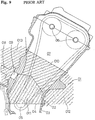
- Figure 9 shows a conventional multicylinder in-line internal combustion engine having a plurality of cylinders tilted at their upper portions toward the front side of the engine. In such an internal combustion engine, an
engine block 01 is formed by integrating a cylinder block and anupper crankcase 02. A crankcase is parted into theupper crankcase 02 of theengine block 01 and alower crankcase 03 along aplane 04. Acrankshaft 05 is rotatably supported in theplane 04, and a main shaft and a counter shaft (both not shown) for supporting gears of a transmission are also rotatably supported in theplane 04. Achain storing chamber 07 for driving overheadvalve operating camshafts 06 is defined between the cylinders adjacent to each other rather than at one of right and left sides of theengine block 01. A supportinghole 09 for supporting atensioner lifter 08 is formed through a wall of thechain storing chamber 07 at an upper side portion thereof so as to be inclined toward a line connecting axial centers of the cylinders. - Conventionally, the
engine block 01 is cast by using a mold as shown in Figure 9. That is, the mold shown is composed of an upperinner mold 010, a lowerinner mold 011, a frontouter mold 012, and a rearouter mold 013. - In the
engine block 01 cast by using the mold shown in Figure 9, a wall thickness of theengine block 01 at a portion thereof near the supportinghole 09 for thetensioner lifter 08 is made large, so as to reliably bear against vibration of a tensioner. Additionally, a padding of the engine block is increased in relation to mold releasing, and blowholes are easily generated. Furthermore, the amount of cutting of the wall of the supportinghole 09 is increased to result in an increase in cutting time and material cost. Accordingly, it is difficult to improve the productivity. - In addition, a conventional four-cycle internal combustion engine is provided with a cam chain tensioner device for removing slack of an endless chain wound around cam sprockets integral with valve operating cams and a sprocket integral with a crankshaft to provide the endless chain with a proper tension.
- A load applied to the valve operating cams is periodically changed in concert with opening and closing timings of intake and exhaust valves, causing a fluctuation in tension of the cam chain. To cope with this problem, Japanese Utility Model Laid Open No. 56-47232 discloses a cam chain tensioner device such that an elastic member is provided under a pin for supporting a lower end of a tensioner body to thereby absorb vibration applied to the tension body due to the fluctuation in the tension of the cam chain.
- In the conventional cam chain tensioner device mentioned above, the vibration along a longitudinal direction of the tensioner body can be absorbed, but the vibration along the width of the cam chain cannot be absorbed.
- The present invention relates to an improvement in a mold for casting a laterally central portion of an engine block, which has solved the above problem. According to the present invention, there is provided in a mold for casting a laterally central portion of an engine block of a multicylinder in-line internal combustion engine having a plurality of cylinders tilted in a longitudinal direction perpendicular to a line of arrangement of the cylinders, a hollow chamber defined between the cylinders adjacent to each other and extending in an axial direction of the cylinders, a hole formed through a wall of the hollow chamber at an upper side portion thereof so as to be inclined downward toward a line connecting axial centers of the cylinders, a crankshaft extending horizontally in a lateral direction parallel to the line of arrangement of the cylinders, and a crankcase parted into an upper crankcase and a lower crankcase along a plane in which a center line of the crankshaft lies, the crankshaft being rotatably supported in the plane between the upper crankcase and the lower crankcase, the upper crankcase being integrated with a cylinder block to form the engine block; the improvement comprising a lower inner mold so formed as to be released downward in a direction perpendicular to the plane, the lower inner mold having a projection projecting upward from an upper portion of an inner opening edge of the hole opening into the hollow chamber to form an upper surface of the hole; an upper inner mold so formed as to be released upward in the axial direction of the cylinders; an upper outer mold so formed as to be released upward in the direction perpendicular to the plane, for forming an upper inclined surface of the engine block, the upper outer mold having a projection projecting downward from a lower portion of an outer opening edge of the hole to form a lower surface of the hole; and a lower outer mold so formed as to be released outward along the plane, for forming a lower inclined surface of the engine block.
- With this arrangement, even when the depth of the hole opening into the hollow chamber is large and the wall thickness of the peripheral wall of the hole is accordingly large, a space surrounded by an inner wall surface of the hole can be partially filled with the projection of the lower inner mold projecting into a part of the hole from the hollow chamber and the projection of the upper outer mold projecting into a part of the hole from the outside of the engine.
- Accordingly, the thickness of the wall of the engine block cast by using the mold according to the present invention can be made as small as possible to thereby suppress the generation of blowholes and reduce the amount of a molten metal to be poured into the mold, thereby reducing a material cost. Furthermore, a cutting time for formation of the hole can be reduced to thereby greatly improve the productivity.
- In addition, a core that must be broken every time of casting is not required to thereby simplify pretreatment and posttreatment of casting, thus contributing to a cost reduction also in this respect.
- The present invention further relates to an improvement in a cam chain tensioner device in an internal combustion engine, which has solved the problem of vibration along the width of the cam chain. According to the present invention, there is provided in a cam chain tensioner device in an internal combustion engine, having a tensioner body formed with a mounting base portion projecting in a lateral direction of the tensioner body, the mounting base portion being mounted in mounting grooves formed on abutting surfaces of upper and lower crankcases of the internal combustion engine and being held between the upper and lower crankcases, the mounting grooves extending in a direction perpendicular to a chain storing portion; the improvement wherein the tensioner body has an elastic member integral therewith, the elastic member being located between opposite side surfaces of the tensioner body and opposite inner wall surfaces of the chain storing portion.
- With this structure of the present invention, a vibrational force applied to the tensioner body in its lateral direction is damped and absorbed by the elastic member held between the opposite side surfaces of the tensioner body and the opposite inner wall surfaces of the chain storing portion.
- In the present invention, the vibrational force in the lateral direction of the articulated cam chain that is prone to vibrate laterally responsive to pulsation of the internal combustion engine can be effectively damped to permit a valve operating mechanism to be operated silently and properly.
- Further scope of applicability of the present invention will become apparent from the detailed description given hereinafter. However, it should be understood that the detailed description and specific examples, while indicating preferred embodiments of the invention, are given by way of illustration only, since various changes and modifications within the spirit and scope of the invention will become apparent to those skilled in the art from this detailed description.
- The present invention will become more fully understood from the detailed description given hereinbelow and the accompanying drawings which are given by way of illustration only, and thus are not limitative of the present invention, and wherein:
- Figure 1 is a general side view of a two-cylinder four-cycle internal combustion engine manufactured by using a mold for casting a laterally central portion of an engine block according to the present invention;
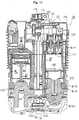
- Figure 2 is a vertical sectional side view of an essential part of the engine shown in Figure 1;
- Figure 3 is a plan view of the engine block of the two cylinder four-cycle internal combustion engine shown in Figure 1;
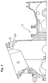
- Figure 4 is a front elevation of the engine block;
- Figure 5 is a vertical section taken along the line V-V in Figure 3;
- Figure 6 is a vertical section taken along the line VI-VI in Figure 3;
- Figure 7 is an enlarged vertical section of a mold as taken along the line VI-VI in Figure 3;
- Figure 8 is an enlarged vertical sectional side view of an essential part showing another preferred embodiment of the present invention;
- Figure 9 is a vertical sectional side view of a mold for an engine block in the prior art.
- Figure 10 is a vertical sectional side view of a cam chain tensioner device in an internal combustion engine according to a preferred embodiment of the present invention;
- Figure 11 is a vertical section taken along the line XI-XI in Figure 10;
- Figure 12 is a view taken in the direction of the arrow XII-XII in Figure 10;
- Figure 13 is a horizontal section taken along the line XIII-XIII in Figure 12;
- Figure 14 is a horizontal section taken along the line XIV-XIV in Figure 12; and
- Figure 15 is a view taken in the direction of the arrow XV-XV in Figure 10.
- A preferred embodiment of the present invention will now be described with reference to Figures 1 to 7.
- As shown in Figure 1, in an overhead valve operating cam type of two-cylinder four-cycle
internal combustion engine 1 to be mounted on a motorcycle (not shown), a crankshaft 6 is rotatably supported through sliding bearings (not shown) between alower crankcase 2 and anengine block 3 as an integrated upper crankcase and cylinder block. Thus, a crankcase of theengine 1 is parted into thelower crankcase 2 and the upper crankcase. Acylinder head 4 is mounted on an upper end of theengine block 3, and ahead cover 5 is mounted on an upper end of thecylinder head 4. Thus, thelower crankcase 2, theengine block 3, thecylinder head 4, and thehead cover 5 are integrally connected together. Thelower crankcase 2, theengine block 3, and thecylinder head 4 are formed by die casting of aluminum or aluminum alloy. - As shown in Figure 2, the crankshaft 6 is connected through connecting rods (not shown) to pistons (not shown) vertically reciprocatably fitted in cylinders 7 (see Fig. 3) of the
engine block 3, so that the crankshaft 6 is rotationally driven by vertical movement of the pistons. - The
cylinder head 4 is provided with intake valves and exhaust valves (both not shown). Valve operating cams (not shown) are located over the intake valves and the exhaust valves on the extensions thereof. Camshafts 9 integral with the valve operating cams are rotatably supported between thecylinder head 4 and a cam holder (not shown). - A cam
chain storing chamber 10 for storing anendless chain 13 to be hereinafter described is defined at a laterally central portion between the right andleft cylinders 7 in theengine block 3. Adrive sprocket 11 is integrally formed on the crankshaft 6 at a central portion thereof, andcam sprockets 12 each having teeth twice in number that of thedrive sprocket 11 is integrally mounted on the camshafts 9 at their central portions. Theendless chain 13 is wound around the drive sprocket 11 and thecam sprockets 12 in the camchain storing chamber 10. Accordingly, two revolutions of the crankshaft 6 bring about one revolution of thecam sprockets 12 and the valve operating cams. - A
chain guide 14 is provided in the camchain storing chamber 10 on the front side of a vehicular body (i.e., on the left side as viewed in Figure 1 where exhaust ports are provided). A camchain tensioner device 15 is provided in the camchain storing chamber 10 on the rear side of the vehicular body (i.e., on the right side as viewed in Figure 1 where intake ports are provided), and achain guide 16 is provided also on the upper side of thecam sprockets 12. The hollow camchain storing chamber 10 comprises a cooling water passage. - The cam
chain tensioner device 15 includes atensioner body 17 formed with a mountingbase portion 18. Apivot pin 19 is integrally fitted with the mountingbase portion 18 of thetensioner body 17. Thepivot pin 19 is pivotally supported between thelower crankcase 2 and theengine block 3. Atensioner lifter 20 is provided on the rear side of thetensioner body 17 at a position somewhat higher than the center of thetensioner body 17. Thetensioner lifter 20 has arod 21 engaging at its tip with arecess 17a formed on a rear surface of thetensioner body 17. Thetensioner lifter 20 is supported in a tensionerlifter supporting hole 22 formed through a rear wall of theengine block 3. Thehole 22 comprises a cooling water communicating hole. Therod 21 of thetensioner lifter 20 is driven by a spring, hydraulic pressure, etc. to forward push thetensioner body 17 regardless of pivotal movement of thetensioner body 17, thereby maintaining a substantially constant tensile condition to theendless chain 13. - As shown in Figure 7, a mold for casting the
engine block 3 is composed of a lower or frontouter mold 23 for defining the shape of a front lower inclined surface of theengine block 3, a upper or rearouter mold 24 for defining the shape of a rear upper inclined surface of theengine block 3 on the side where the camchain tensioner device 15 is provided, a leftouter mold 25 for defining the shape of a left surface of the engine block 3 (see Figure 4 showing a front elevation of theengine block 3, so that the leftouter mold 25 is shown on the right-hand side as viewed in Figure 4), a rightouter mold 26 for defining the shape of a right surface of the engine block 3 (see Figure 4), an upperinner mold 27 for defining the shape of an upper surface of theengine block 3 and retainingcylinder liners 8, and a lowerinner mold 28 for defining the shape of a lower surface of theengine block 3. - As shown in Figure 6, the upper
inner mold 27 has right and leftliner retaining projections 29 projecting downward so as to retain thecylinder liners 8 in the right and leftcylinders 7 and close the bottom surfaces of thecylinder liners 8. As shown in Figure 7, the upperinner mold 27 is integrally formed with a cam chain storing chamber upperinner mold 30 disposed intermediate of the right and leftliner retaining projections 29, for defining an upper portion of an inner surface of the tensionerlifter supporting hole 22. - As shown in Figure 7, the lower
inner mold 28 is formed with a cam chain storing chamber lowerinner mold 31 opposed to the cam chain storing chamber upperinner mold 30 of the upperinner mold 27, for defining a lower portion of the inner surface of the tensionerlifter supporting hole 22. The lowerinner mold 28 is further formed with anupper projection 32 projecting upward from an inner opening edgeupper portion 22a of the tensionerlifter supporting hole 22 facing the camchain storing chamber 10. - The upper or rear
outer mold 24 is formed with alower projection 33 projecting downward from an outer opening edgelower portion 22b of the tensionerlifter supporting hole 22 facing the camchain storing chamber 10. - The cam chain storing chamber upper
inner mold 30 of the upperinner mold 27 and the cam chain storing chamber lowerinner mold 31 of the lowerinner mold 28 are so formed as to contact together through abent parting surface 34 inclined upward toward the rear side gradually at a front portion and steeply at a rear portion. - In this preferred embodiment shown in Figures 1 to 7, the lower or front
outer mold 23, the upper or rearouter mold 24, the leftouter mold 25, the rightouter mold 26, the upperinner mold 27, and the lowerinner mold 28 are jointed together at their mating faces, and such a joined mold is set in a die casting apparatus (not shown). Then, the die casting apparatus is operated to pour a molten metal into the mold under pressure, thus obtaining a die casting. - In the
engine block 3 thus cast, the camchain storing chamber 10 is formed without the need of any machining. In particular, a wall thickness t of a portion for defining the tensionerlifter supporting hole 22 facing the camchain storing chamber 10 is made smaller than a wall thickness T of a thick-walled peripheral wall of the tensionerlifter supporting hole 22 by theupper projection 32 and thelower projection 33. Furthermore, the wall thickness T of the peripheral wall of the tensionerlifter supporting hole 22 is set to a thickness enough to bear against an external force due to vibration or the like applied to the camchain tensioner device 15. Accordingly, the amount of the molten metal to be required can be minimized to thereby reduce a material cost. - Accordingly, the amount of cutting of the wall of the tensioner
lifter supporting hole 22 can be greatly reduced with the result that a working time can be greatly reduced to thereby greatly improve the productivity. - Further, no core that must be broken every time of casting is required to thereby simplify pretreatment and posttreatment of casting, thus contributing to a cost reduction also in this respect.
- As another preferred embodiment shown in Figure 8, a
recess 35 may be formed on the cam chain storing chamber upperinner mold 30 at a position adjacent to anupper portion 34a of thebent parting surface 34 and facing the camchain storing chamber 10. With this structure, a vibration stop for suppressing lateral vibration of thetensioner body 17 can be formed in the camchain storing chamber 10. - Further, the shape of the
bent parting surface 34 may be modified as shown by a broken line in Figure 8 to change the position of therecess 35. - A preferred embodiment of the present invention will now be described with reference to Figures 10 to 15.
- In an overhead valve operating cam type of two-cylinder four-cycle
internal combustion engine 101 to be mounted on a motorcycle (not shown), acrankshaft 107 is rotatably supported through slidingbearings 106, see Fig. 11, between alower crankcase 102 and anengine block 103 as an integrated upper crankcase and cylinder block. Thus, a crankcase of theengine 101 is parted into thelower crankcase 102 and the upper crankcase. Acylinder head 104 is mounted on an upper end of theengine block 103, and ahead cover 105 is mounted on an upper end of thecylinder head 104. Thus, thelower crankcase 102, theengine block 103, thecylinder head 104, and thehead cover 105 are integrally connected together. - As shown in Fig. 11, the
crankshaft 107 is connected through connectingrods 110 topistons 109 vertically reciprocatably fitted incylinders 108 of theengine block 103, so that thecrankshaft 107 is rotationally driven by vertical movement of thepistons 109. - The
cylinder head 104 is provided withintake valves 111 and exhaust valves (not shown).Valve operating cams 112 are located over theintake valves 111 and the exhaust valves on the extensions thereof.Camshafts 113 integral with thevalve operating cams 112 are rotatably supported between thecylinder head 104 and acam holder 132. - A sprocket 114 is integrally formed on the
crankshaft 107 at a central portion thereof, andcam sprockets 115 each having teeth twice in number that of the sprocket 114 is integrally mounted on thecamshafts 113 at their central portions. Anendless chain 116 is wound around the sprocket 114 and thecam sprockets 115. Accordingly, two revolutions of thecrankshaft 107 bring about one revolution of thecam sprockets 115 and thevalve operating cams 112. - A cam
chain storing chamber 117 is defined in theengine block 103 and thecylinder head 104 at a position between the right and leftcylinders 108. Achain guide 118 is provided in the camchain storing chamber 117 on the front side of a vehicular body (i.e., on the side of exhaust ports). A camchain tensioner device 120 is provided in the camchain storing chamber 117 on the rear side of the vehicular body (i.e., on the side of intake ports), and a chain guide 119 is provided also on the upper side of thecam sprockets 115. - The cam
chain tensioner device 120 includes atensioner body 123 consisting of asteel strip 121 and arubber cushion 122 integrally bonded to a front surface and a lower end portion of thesteel strip 121. A steel pivot,pin 125 is integrally fitted with a mountingbase portion 124 of thetensioner body 123. Further, aguide member 126 formed of a Teflon resin is integrally laminated on a front surface of therubber cushion 122 which theendless chain 116 is in contact with. Anupper half portion 126a of theguide member 126 is formed with a groove. - A lifter 128 is provided on the rear side of the
tensioner body 123 at a position somewhat higher than the center of thetensioner body 123. The lifter 128 has arod 129 engaging at its tip with arecess 127 formed on a rear surface of thetensioner body 123. Therecess 127 has a width substantially equal to the diameter of therod 129. Therod 129 of the lifter 128 is driven by a spring, hydraulic pressure, etc. to forward push thetensioner body 123 regardless of pivotal movement of thetensioner body 123, thereby maintaining a substantially constant tensile condition to theendless chain 116. - The
pivot pin 125 integral with thetensioner body 123 is pivotally engaged at its opposite ends withrecesses 130 formed on theengine block 103, and is held between therecesses 130 and thelower crankcase 102. Abase portion 122a of therubber cushion 122 at the mountingbase portion 124 of thetensioner body 123 is held between right and left inner wall surfaces 117a of the camchain storing chamber 117. - The operation of the above preferred embodiment shown in Figures 10 to 15 will now be described. When the four-cycle
internal combustion engine 101 starts operating, rotation of thecrankshaft 107 is transmitted through the sprocket 114, theendless chain 116, thecam sprockets 115, and thecamshafts 113 to thevalve operating cams 112 with the speed of the rotation reduced to one half. Accordingly,slippers 131 mounted on the tops of theintake valves 111 and the exhaust valves are pushed downward by thevalve operating cams 112 in concert with vertical movement of thepistons 109, thereby intermittently opening theintake valves 111 and the exhaust valves. - In such an intermittent opening operation of the
intake valves 111 and the exhaust valves, a load applied to thecamshafts 113 is periodically increased to result in an increase in tension of theendless chain 116. Accordingly, the tensile condition of theendless chain 116 periodically changes. However, thetensioner body 123 is pushed forward, by the lifter 128 to prevent longitudinal vibration of theendless chain 116. - Furthermore, even when a lateral force is generated in the
endless chain 116 to cause lateral vibration, the lateral vibration of theendless chain 116 can be reliably suppressed for the following reason. That is, theendless chain 116 is fitted in thegroove 126a of theguide member 126 of thetensioner body 123. Further, the tip of therod 129 of the lifter 128 is fitted in therecess 127 of thetensioner body 123, and both ends of thebase portion 122a of therubber cushion 122 at the mountingbase portion 124 of thetensioner body 123 are held by the right and left inner wall surfaces 117a of the camchain storing chamber 117, thereby elastically restrict lateral movement of thetensioner body 123. - The invention being thus described, it will be obvious that the same may be varied in many ways. Such variations are not to be regarded as a departure from the spirit and scope of the invention, and all such modifications as would be obvious to one skilled in the art are intended to be included within the scope of the following claims.
Claims (5)
- In a mold for casting a laterally central portion of an engine block of a multicylinder in-line internal combustion engine having a plurality of cylinders tilted in a longitudinal direction perpendicular to a line of arrangement of said cylinders, a hollow chamber defined between said cylinders adjacent to each other and extending in an axial direction of said cylinders, a hole formed through a wall of said hollow chamber at an upper side portion thereof so as to be inclined downward toward a line connecting axial centers of said cylinders, a crankshaft extending horizontally in a lateral direction parallel to said line of arrangement of said cylinders, and a crankcase parted into an upper crankcase and a lower crankcase along a plane in which a center line of said crankshaft lies, said crankshaft being rotatably supported in said plane between said upper crankcase and said lower crankcase, said upper crankcase being integrated with a cylinder block to form said engine block, said mold comprising:
a lower inner mold so formed as to be released downward in a direction perpendicular to said plane, said lower inner mold having a projection projecting upward from an upper portion of an inner opening edge of said hole opening into said hollow chamber to form an upper surface of said hole;
an upper inner mold so formed as to be released upward in said axial direction of said cylinders;
an upper outer mold so formed as to be released upward in said direction perpendicular to said plane, for forming an upper inclined surface of said engine block, said upper outer mold having a projection projecting downward from a lower portion of an outer opening edge of said hole to form a lower surface of said hole; and
a lower outer mold so formed as to be released outward along said plane, for forming a lower inclined surface of said engine block. - A mold for casting a laterally central portion of an engine block according to claim 1, wherein said hollow chamber comprises a chain storing chamber for driving overhead valve operating camshafts, and said hole comprises a tensioner lifter supporting hole.
- A mold for casting a laterally central portion of an engine block according to claim 1, wherein said hollow chamber comprises a cooling water passage, and said hole comprises a cooling water communicating hole.
- A mold for casting a laterally central portion of an engine block according to claim 1, wherein said upper inner mold includes right and left cylinder liner retaining projections.
- A mold for casting a laterally central portion of an engine block according to claim 4, wherein said right and left cylinder liner retaining projections project downward from said upper inner mold so as to retain a pair of cylinder liners in a right and left cylinder and close the bottom surfaces of said cylinder liners.
Applications Claiming Priority (2)
| Application Number | Priority Date | Filing Date | Title |
|---|---|---|---|
| JP23740393A JP3226680B2 (en) | 1993-08-30 | 1993-08-30 | Engine block width direction center mold |
| JP237403/93 | 1993-08-30 |
Publications (2)
| Publication Number | Publication Date |
|---|---|
| EP0657234A1 true EP0657234A1 (en) | 1995-06-14 |
| EP0657234B1 EP0657234B1 (en) | 1998-12-02 |
Family
ID=17014879
Family Applications (1)
| Application Number | Title | Priority Date | Filing Date |
|---|---|---|---|
| EP19940113530 Expired - Lifetime EP0657234B1 (en) | 1993-08-30 | 1994-08-30 | Mold for casting a laterally central portion of an engine block |
Country Status (4)
| Country | Link |
|---|---|
| EP (1) | EP0657234B1 (en) |
| JP (1) | JP3226680B2 (en) |
| DE (1) | DE69414986T2 (en) |
| ES (1) | ES2125385T3 (en) |
Cited By (1)
| Publication number | Priority date | Publication date | Assignee | Title |
|---|---|---|---|---|
| US7814879B2 (en) | 2008-04-23 | 2010-10-19 | Techtronic Outdoor Products Technology Limited | Monolithic block and valve train for a four-stroke engine |
Families Citing this family (2)
| Publication number | Priority date | Publication date | Assignee | Title |
|---|---|---|---|---|
| US7405582B2 (en) | 2006-06-01 | 2008-07-29 | Advantest Corporation | Measurement board for electronic device test apparatus |
| CN105964914B (en) * | 2016-07-25 | 2017-11-24 | 大连金河铸造有限公司 | Diesel engine cylinder block cam chamber antiseep casting technique |
Citations (3)
| Publication number | Priority date | Publication date | Assignee | Title |
|---|---|---|---|---|
| DE84304C (en) * | ||||
| DD109333A1 (en) * | 1974-01-15 | 1974-11-05 | ||
| US4757857A (en) * | 1985-12-18 | 1988-07-19 | Fritz Winter Eisengiesserei O.H.G. | Mold for casting cylinder blocks of combustion engines |
-
1993
- 1993-08-30 JP JP23740393A patent/JP3226680B2/en not_active Expired - Fee Related
-
1994
- 1994-08-30 ES ES94113530T patent/ES2125385T3/en not_active Expired - Lifetime
- 1994-08-30 EP EP19940113530 patent/EP0657234B1/en not_active Expired - Lifetime
- 1994-08-30 DE DE1994614986 patent/DE69414986T2/en not_active Expired - Fee Related
Patent Citations (3)
| Publication number | Priority date | Publication date | Assignee | Title |
|---|---|---|---|---|
| DE84304C (en) * | ||||
| DD109333A1 (en) * | 1974-01-15 | 1974-11-05 | ||
| US4757857A (en) * | 1985-12-18 | 1988-07-19 | Fritz Winter Eisengiesserei O.H.G. | Mold for casting cylinder blocks of combustion engines |
Non-Patent Citations (1)
| Title |
|---|
| DATABASE WPI Week 7507, Derwent World Patents Index; AN 75-10928W 07! * |
Cited By (1)
| Publication number | Priority date | Publication date | Assignee | Title |
|---|---|---|---|---|
| US7814879B2 (en) | 2008-04-23 | 2010-10-19 | Techtronic Outdoor Products Technology Limited | Monolithic block and valve train for a four-stroke engine |
Also Published As
| Publication number | Publication date |
|---|---|
| DE69414986D1 (en) | 1999-01-14 |
| JP3226680B2 (en) | 2001-11-05 |
| DE69414986T2 (en) | 1999-04-22 |
| JPH0760404A (en) | 1995-03-07 |
| ES2125385T3 (en) | 1999-03-01 |
| EP0657234B1 (en) | 1998-12-02 |
Similar Documents
| Publication | Publication Date | Title |
|---|---|---|
| JPS6352201B2 (en) | ||
| JP4197067B2 (en) | Power transmission device for vehicle engine | |
| JP4361772B2 (en) | Four-cycle engine valve gear | |
| EP0657234A1 (en) | Mold for casting a laterally central portion of an engine block | |
| JPH0211830A (en) | Cam chain tensioner for four cycle engine | |
| JP2018054061A (en) | Internal combustion engine | |
| JP3166532B2 (en) | Chain case structure of internal combustion engine | |
| EP1609959B1 (en) | Engine | |
| JPH086564B2 (en) | Camshaft drive for V-type DOHC engine | |
| JPH08200088A (en) | Chain case structure of internal combustion engine | |
| JP3157365B2 (en) | Cam chain tensioner device for internal combustion engine | |
| JP7363350B2 (en) | Engine auxiliary equipment mounting structure | |
| JP4544100B2 (en) | Engine front structure | |
| JP4047923B2 (en) | Cam chain guide mounting structure | |
| JP4603206B2 (en) | V-type engine | |
| JP4996557B2 (en) | engine | |
| JPS6345566Y2 (en) | ||
| JPH1130129A (en) | Cam chain guide for four-cycle engine | |
| CN211852698U (en) | Hydraulic tensioner device | |
| JP2741078B2 (en) | Camshaft drive for V-type water-cooled engine | |
| JP2522644Y2 (en) | Timing chain lubrication device | |
| JP3862462B2 (en) | Cam follower drop-off prevention structure | |
| JPH10281244A (en) | Support structure of timing chain guide member of engine | |
| JPH11182325A (en) | Cylinder block for multicylinder engine | |
| JPH0732884Y2 (en) | Lubricating oil passage for V-type engine |
Legal Events
| Date | Code | Title | Description |
|---|---|---|---|
| PUAI | Public reference made under article 153(3) epc to a published international application that has entered the european phase |
Free format text: ORIGINAL CODE: 0009012 |
|
| 17P | Request for examination filed |
Effective date: 19941220 |
|
| AK | Designated contracting states |
Kind code of ref document: A1 Designated state(s): DE ES FR GB |
|
| 17Q | First examination report despatched |
Effective date: 19970618 |
|
| GRAG | Despatch of communication of intention to grant |
Free format text: ORIGINAL CODE: EPIDOS AGRA |
|
| GRAG | Despatch of communication of intention to grant |
Free format text: ORIGINAL CODE: EPIDOS AGRA |
|
| GRAH | Despatch of communication of intention to grant a patent |
Free format text: ORIGINAL CODE: EPIDOS IGRA |
|
| GRAH | Despatch of communication of intention to grant a patent |
Free format text: ORIGINAL CODE: EPIDOS IGRA |
|
| GRAA | (expected) grant |
Free format text: ORIGINAL CODE: 0009210 |
|
| AK | Designated contracting states |
Kind code of ref document: B1 Designated state(s): DE ES FR GB |
|
| REF | Corresponds to: |
Ref document number: 69414986 Country of ref document: DE Date of ref document: 19990114 |
|
| REG | Reference to a national code |
Ref country code: ES Ref legal event code: FG2A Ref document number: 2125385 Country of ref document: ES Kind code of ref document: T3 |
|
| ET | Fr: translation filed | ||
| PLBE | No opposition filed within time limit |
Free format text: ORIGINAL CODE: 0009261 |
|
| STAA | Information on the status of an ep patent application or granted ep patent |
Free format text: STATUS: NO OPPOSITION FILED WITHIN TIME LIMIT |
|
| 26N | No opposition filed | ||
| REG | Reference to a national code |
Ref country code: GB Ref legal event code: IF02 |
|
| PGFP | Annual fee paid to national office [announced via postgrant information from national office to epo] |
Ref country code: FR Payment date: 20050809 Year of fee payment: 12 |
|
| PGFP | Annual fee paid to national office [announced via postgrant information from national office to epo] |
Ref country code: DE Payment date: 20050825 Year of fee payment: 12 |
|
| PG25 | Lapsed in a contracting state [announced via postgrant information from national office to epo] |
Ref country code: DE Free format text: LAPSE BECAUSE OF NON-PAYMENT OF DUE FEES Effective date: 20070301 |
|
| REG | Reference to a national code |
Ref country code: FR Ref legal event code: ST Effective date: 20070430 |
|
| PGFP | Annual fee paid to national office [announced via postgrant information from national office to epo] |
Ref country code: ES Payment date: 20070926 Year of fee payment: 14 |
|
| PGFP | Annual fee paid to national office [announced via postgrant information from national office to epo] |
Ref country code: GB Payment date: 20070829 Year of fee payment: 14 |
|
| PG25 | Lapsed in a contracting state [announced via postgrant information from national office to epo] |
Ref country code: FR Free format text: LAPSE BECAUSE OF NON-PAYMENT OF DUE FEES Effective date: 20060831 |
|
| GBPC | Gb: european patent ceased through non-payment of renewal fee |
Effective date: 20080830 |
|
| REG | Reference to a national code |
Ref country code: ES Ref legal event code: FD2A Effective date: 20080901 |
|
| PG25 | Lapsed in a contracting state [announced via postgrant information from national office to epo] |
Ref country code: GB Free format text: LAPSE BECAUSE OF NON-PAYMENT OF DUE FEES Effective date: 20080830 |
|
| PG25 | Lapsed in a contracting state [announced via postgrant information from national office to epo] |
Ref country code: ES Free format text: LAPSE BECAUSE OF NON-PAYMENT OF DUE FEES Effective date: 20080901 |