EP0657757B1 - Optical fiber distribution apparatus - Google Patents
Optical fiber distribution apparatus Download PDFInfo
- Publication number
- EP0657757B1 EP0657757B1 EP94309010A EP94309010A EP0657757B1 EP 0657757 B1 EP0657757 B1 EP 0657757B1 EP 94309010 A EP94309010 A EP 94309010A EP 94309010 A EP94309010 A EP 94309010A EP 0657757 B1 EP0657757 B1 EP 0657757B1
- Authority
- EP
- European Patent Office
- Prior art keywords
- tray
- fibers
- rear portion
- shelf
- connectors
- Prior art date
- Legal status (The legal status is an assumption and is not a legal conclusion. Google has not performed a legal analysis and makes no representation as to the accuracy of the status listed.)
- Expired - Lifetime
Links
- 239000013307 optical fiber Substances 0.000 title claims description 14
- 239000000835 fiber Substances 0.000 claims description 45
- 230000003287 optical effect Effects 0.000 claims description 6
- 230000005540 biological transmission Effects 0.000 description 4
- 238000012423 maintenance Methods 0.000 description 1
- 238000012986 modification Methods 0.000 description 1
- 230000004048 modification Effects 0.000 description 1
- 230000001681 protective effect Effects 0.000 description 1
Images

Classifications
-
- G—PHYSICS
- G02—OPTICS
- G02B—OPTICAL ELEMENTS, SYSTEMS OR APPARATUS
- G02B6/00—Light guides; Structural details of arrangements comprising light guides and other optical elements, e.g. couplings
- G02B6/44—Mechanical structures for providing tensile strength and external protection for fibres, e.g. optical transmission cables
- G02B6/4439—Auxiliary devices
- G02B6/444—Systems or boxes with surplus lengths
- G02B6/4453—Cassettes
- G02B6/4455—Cassettes characterised by the way of extraction or insertion of the cassette in the distribution frame, e.g. pivoting, sliding, rotating or gliding
-
- G—PHYSICS
- G02—OPTICS
- G02B—OPTICAL ELEMENTS, SYSTEMS OR APPARATUS
- G02B6/00—Light guides; Structural details of arrangements comprising light guides and other optical elements, e.g. couplings
- G02B6/44—Mechanical structures for providing tensile strength and external protection for fibres, e.g. optical transmission cables
- G02B6/4439—Auxiliary devices
- G02B6/444—Systems or boxes with surplus lengths
- G02B6/4452—Distribution frames
- G02B6/44524—Distribution frames with frame parts or auxiliary devices mounted on the frame and collectively not covering a whole width of the frame or rack
-
- G—PHYSICS
- G02—OPTICS
- G02B—OPTICAL ELEMENTS, SYSTEMS OR APPARATUS
- G02B6/00—Light guides; Structural details of arrangements comprising light guides and other optical elements, e.g. couplings
- G02B6/44—Mechanical structures for providing tensile strength and external protection for fibres, e.g. optical transmission cables
- G02B6/4439—Auxiliary devices
- G02B6/444—Systems or boxes with surplus lengths
- G02B6/44528—Patch-cords; Connector arrangements in the system or in the box
-
- G—PHYSICS
- G02—OPTICS
- G02B—OPTICAL ELEMENTS, SYSTEMS OR APPARATUS
- G02B6/00—Light guides; Structural details of arrangements comprising light guides and other optical elements, e.g. couplings
- G02B6/44—Mechanical structures for providing tensile strength and external protection for fibres, e.g. optical transmission cables
- G02B6/4439—Auxiliary devices
- G02B6/444—Systems or boxes with surplus lengths
- G02B6/4453—Cassettes
Definitions
- This invention relates to optical fiber trays used in fiber distribution frames.
- Optical fiber distribution frames are important components in telecommunications systems as an interface between optical fiber feeder (trunk) and distribution (transmission) cables.
- the feeder cables are fed into each tray of the frame from the back or side of the tray in the form of bundled fibers covered by protective tubing.
- the individual fibers are spliced to fiber pigtails on a splice tray, and optical connectors on the opposite ends of the pigtails are mounted in a panel near the front of the tray (see, e.g., U.S. Pat. No. 5,071,211 and U.S. Pat. No. 4,898,448).
- Jumper cables are optically connected to the pigtail fibers by means of the connectors at the front of the trays for optical connection to other equipment.
- the fiber trays are usually slidable within a shelf, and can include a drop-down portion for access to the connectors (see, e.g., U.S. Pat. No. 5,129,030 and U.S. Pat. No. 5,071,211).
- US-A-4911662 discloses a distribution frame having a termination shelf for a telecommunications cable.
- the feeder cables are fed into the trays from the back.
- the feeder cables are usually provided in the front of the trays.
- the invention is an optical fiber distribution tray adapted for slidable mounting within a shelf of a distribution frame.
- Each tray includes a front and rear portion.
- the rear portion includes a plurality of optical connectors.
- the front portion includes means for distributing optical fibers coupled to said connectors and comprises a base member and a front surface essentially perpendicular thereto.
- the base member is mounted by means of hinges to the rear portion of the tray.
- a cover is mounted by means of hinges to the front surface of the distributing means so as to be essentially parallel to the base member and provide protection for the fibers and connectors.
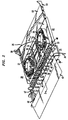
- FIG. 1 illustrates a fiber distribution frame, 10, which utilizes an embodiment of the invention.
- the frame includes a plurality of shelves, e.g., 11 and 14, which, in this example, are arranged in two columns.
- Each shelf includes a plurality of trays, to be described, where optical fibers from a trunk cable 12 or transmission cable 13 are connected with jumper fibers, e.g., 15, for purposes of cross-connection between the cables.
- the trunk cable 12 or transmission cable 13 is brought into the frame at the back and fibers from the cable are introduced into each tray through an aperture which can be located at the front or rear of the shelves.
- a set of jumper fibers, 15, are shown connected from the tray in shelf 11 through an aperture 16 to the tray in shelf 14 through an aperture 17.
- any fiber from the trunk cable can be cross-connected with any fiber from the transmission cable through jumpers between appropriate shelves.
- the particular distribution frame illustrated is designed to be mounted to a frame in the central office for lightguide cross-connect applications. It will be appreciated that the invention is equally applicable to interconnect applications where the cables as well as the jumper fibers are positioned at the front of the shelves.
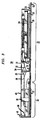
- the tray 20 includes a front portion, 21, and a rear portion, 22.
- the rear portion 22 includes a base member, 23, which is capable of sliding into grooves in the shelf (e.g., 51).
- a raised platform, 24, is mounted to the base 23 so as to form a compartment, 25, therebetween of sufficient height to provide room to store the fibers from the feeder cable (12 of FIG. 1) which are brought into the shelf 51 through an aperture, 50, in the shelf.
- the fiber usually comes into the shelf protected by an outer tubing. Only one such fiber, 26, is shown in FIGS. 2 and 3 for clarity in the illustration.
- the height of the compartment 25 would be in the range 0.5-0.65 cm.
- the platform 24 includes on its top surface a pair of drums, 27 and 28, which are adapted for storing additional lengths of optical fiber.
- drum 27 receives the fiber 26 from the compartment 25 as it exits the compartment at its forward end.
- a standard splice tray, 30, mounted between the drums.
- pigtail fiber 31, which is stored on drum 28.
- the opposite end of fiber 31 terminates in an optical connector 32 which can be a standard type, such as an ST connector.
- a bulkhead, 33 is mounted near the front of the base 23.
- the bulkhead includes a plurality of apertures which receive therein corresponding sleeves, only one of which is shown as 34, for providing optical connection between the pigtail connectors and corresponding connectors coupled to jumper fibers. Again, only a single jumper fiber, 36, with a connector, 35, coupled thereto is shown optically connected to pigtail fiber 31.
- the front portion 21 of the tray also includes a base member, 37. Attached thereto, or integral therewith, is a front surface, 38, which is essentially perpendicular to the base 37. Both sides of the base member 37 are open to permit the exit of jumper fibers (e.g., 36) from the tray.
- a series of posts, e.g., 39, is provided on the base member 37 adjacent to the bulkhead 33. By threading a plurality of jumper fibers through each space between the posts, strain relief is provided for the fibers.
- a cover, 43 Mechanically coupled by means of hinges 40-42 to the top of the front surface 38 is a cover, 43, shown in an open position in FIG. 2 and in a closed position in FIG. 3.
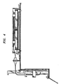
- the base member 37 of the front portion 21 is mechanically coupled to the base member 23 of the rear portion 22 by means of hinges 44-47. As shown in FIG. 4, this hinged attachment of the front and rear portions permits the front portion 21 to drop down and provide easy access to the connectors in the bulkhead 33.
- the cover 43 is closed (as shown in FIG. 3) so as to protect the jumper fibers 36, the connectors 32 and 35, and sleeves 34 from getting damaged.
- the incoming fibers, e.g., 26, will be coiled in the compartment 25 formed between the base member 23 and the platform 24. Typically, approximately 61 cm of fiber length will be stored. Generally, the length of each fiber in the compartment will be 50-70 cm.
- the cover 43 When the tray is extended sufficiently, the cover 43 can be pivoted to the open position and the front portion 21 pivoted downward to provide access to the connectors (e.g., 35). At this stage, the splice tray 30 can remain within the shelf boundaries. If it is desired to access the splice tray 30, the tray 20 can be pulled out to its fully extended position (FIG. 2).
- the front portion 21 may be kept in its horizontal position by means of latches, e.g., 48, coupled to the bulkhead 33. This permits the portion 21 to remain horizontal even when the tray is pulled out to its fully extended position so that the cover 43 will protect the connectors while a craftsperson has access to the splice tray in the rear portion.
- latches e.g., 48
- the uncoiled fiber (26) will automatically slide back into and coil itself within the compartment 25. This operation is aided by the edge 52 of the tray which is slightly bent downward to "shovel" the fiber 26 back into the compartment.
- a further desirable feature is the use of hinges 44-47 which are easily removed from the base 23 of the rear portion 22 by an upward rotation of the front portion from its horizontal position. The removal of the front portion permits the rear portion to be slid out of the front or back of the shelf so that a craftsperson can work on the splices or connectors at some work surface removed from the shelf.
Description
- This invention relates to optical fiber trays used in fiber distribution frames.
- Optical fiber distribution frames are important components in telecommunications systems as an interface between optical fiber feeder (trunk) and distribution (transmission) cables. Typically, the feeder cables are fed into each tray of the frame from the back or side of the tray in the form of bundled fibers covered by protective tubing. The individual fibers are spliced to fiber pigtails on a splice tray, and optical connectors on the opposite ends of the pigtails are mounted in a panel near the front of the tray (see, e.g., U.S. Pat. No. 5,071,211 and U.S. Pat. No. 4,898,448). Jumper cables are optically connected to the pigtail fibers by means of the connectors at the front of the trays for optical connection to other equipment.
- In such frames, it is desirable to provide as high a density of fibers and connectors as possible while still permitting easy access to the connectors and splice trays for proper maintenance. For access purposes the fiber trays are usually slidable within a shelf, and can include a drop-down portion for access to the connectors (see, e.g., U.S. Pat. No. 5,129,030 and U.S. Pat. No. 5,071,211).
- US-A-4911662 discloses a distribution frame having a termination shelf for a telecommunications cable.
- The use of movable trays can create problems as to how or where excess fiber can be stored within the apparatus, especially in high density applications. A further concern is how to protect the connectors and splices in a manner consistent with easy access.
- In lightguide cross-connection applications typically used in central offices, the feeder cables are fed into the trays from the back. However, for interconnection applications such as typically used for cable television, the feeder cables are usually provided in the front of the trays.
- It is the object of the present invention to provide an optical fiber distribution tray which can receive a cable from the front or back or the frame and which provides protection for the cable.
- This object is achieved by an optical fiber distribution tray according to claim 1.
- In accordance with one aspect, the invention is an optical fiber distribution tray adapted for slidable mounting within a shelf of a distribution frame. Each tray includes a front and rear portion. The rear portion includes a plurality of optical connectors. The front portion includes means for distributing optical fibers coupled to said connectors and comprises a base member and a front surface essentially perpendicular thereto. The base member is mounted by means of hinges to the rear portion of the tray. A cover is mounted by means of hinges to the front surface of the distributing means so as to be essentially parallel to the base member and provide protection for the fibers and connectors.
- These and other features of the invention are delineated in detail in the following description. In the drawing:
- FIG. 1 is a perspective view of an optical fiber distribution frame in accordance with an embodiment of the invention;
- FIG. 2 is a perspective view of a tray and shelf in accordance with an embodiment of the invention which are part of the frame of FIG. 1; and
- FIGS. 3 and 4 are cross-sectional views of the tray taken along line 3-3 of FIG. 2.
-
- It will be appreciated that, for purposes of illustration, these figures are not necessarily made to scale.
- FIG. 1 illustrates a fiber distribution frame, 10, which utilizes an embodiment of the invention. The frame includes a plurality of shelves, e.g., 11 and 14, which, in this example, are arranged in two columns. Each shelf includes a plurality of trays, to be described, where optical fibers from a trunk cable 12 or transmission cable 13 are connected with jumper fibers, e.g., 15, for purposes of cross-connection between the cables. Typically, the trunk cable 12 or transmission cable 13 is brought into the frame at the back and fibers from the cable are introduced into each tray through an aperture which can be located at the front or rear of the shelves.
- For purposes of illustration, a set of jumper fibers, 15, are shown connected from the tray in shelf 11 through an
aperture 16 to the tray inshelf 14 through anaperture 17. Of course, any fiber from the trunk cable can be cross-connected with any fiber from the transmission cable through jumpers between appropriate shelves. - The particular distribution frame illustrated is designed to be mounted to a frame in the central office for lightguide cross-connect applications. It will be appreciated that the invention is equally applicable to interconnect applications where the cables as well as the jumper fibers are positioned at the front of the shelves.
- An example of a slide-out tray is illustrated in the perspective view of FIG. 2 and the cross-sectional views of FIG. 3 and 4. The
tray 20 includes a front portion, 21, and a rear portion, 22. Therear portion 22 includes a base member, 23, which is capable of sliding into grooves in the shelf (e.g., 51). A raised platform, 24, is mounted to thebase 23 so as to form a compartment, 25, therebetween of sufficient height to provide room to store the fibers from the feeder cable (12 of FIG. 1) which are brought into theshelf 51 through an aperture, 50, in the shelf. The fiber usually comes into the shelf protected by an outer tubing. Only one such fiber, 26, is shown in FIGS. 2 and 3 for clarity in the illustration. Typically, the height of thecompartment 25 would be in the range 0.5-0.65 cm. - The
platform 24 includes on its top surface a pair of drums, 27 and 28, which are adapted for storing additional lengths of optical fiber. In this example,drum 27 receives thefiber 26 from thecompartment 25 as it exits the compartment at its forward end. Mounted between the drums is a standard splice tray, 30, for joiningfiber 26 to a pigtail fiber, 31, which is stored ondrum 28. Again, it will be appreciated that several incoming fibers will be joined to several corresponding pigtail fibers, but these additional fibers are not shown for purposes of clarity. As the term "pigtail fiber" connotes, the opposite end offiber 31 terminates in anoptical connector 32 which can be a standard type, such as an ST connector. - A bulkhead, 33, is mounted near the front of the
base 23. The bulkhead includes a plurality of apertures which receive therein corresponding sleeves, only one of which is shown as 34, for providing optical connection between the pigtail connectors and corresponding connectors coupled to jumper fibers. Again, only a single jumper fiber, 36, with a connector, 35, coupled thereto is shown optically connected topigtail fiber 31. - The
front portion 21 of the tray also includes a base member, 37. Attached thereto, or integral therewith, is a front surface, 38, which is essentially perpendicular to thebase 37. Both sides of thebase member 37 are open to permit the exit of jumper fibers (e.g., 36) from the tray. A series of posts, e.g., 39, is provided on thebase member 37 adjacent to thebulkhead 33. By threading a plurality of jumper fibers through each space between the posts, strain relief is provided for the fibers. - Mechanically coupled by means of hinges 40-42 to the top of the
front surface 38 is a cover, 43, shown in an open position in FIG. 2 and in a closed position in FIG. 3. - The
base member 37 of thefront portion 21 is mechanically coupled to thebase member 23 of therear portion 22 by means of hinges 44-47. As shown in FIG. 4, this hinged attachment of the front and rear portions permits thefront portion 21 to drop down and provide easy access to the connectors in thebulkhead 33. - While the
tray 24 is within its shelf, 51, thecover 43 is closed (as shown in FIG. 3) so as to protect thejumper fibers 36, theconnectors compartment 25 formed between thebase member 23 and theplatform 24. Typically, approximately 61 cm of fiber length will be stored. Generally, the length of each fiber in the compartment will be 50-70 cm. When the tray is pulled out of the shelf, the storedfiber 26 will automatically slide out of thecompartment 25 and come to rest on thefloor 53 of the shelf. Thus, the tray can be pulled out with a minimum of disturbance to the fiber. When the tray is extended sufficiently, thecover 43 can be pivoted to the open position and thefront portion 21 pivoted downward to provide access to the connectors (e.g., 35). At this stage, thesplice tray 30 can remain within the shelf boundaries. If it is desired to access thesplice tray 30, thetray 20 can be pulled out to its fully extended position (FIG. 2). - It will also be noted that the
front portion 21 may be kept in its horizontal position by means of latches, e.g., 48, coupled to thebulkhead 33. This permits theportion 21 to remain horizontal even when the tray is pulled out to its fully extended position so that thecover 43 will protect the connectors while a craftsperson has access to the splice tray in the rear portion. When it is desired to slide the tray back into the shelf, the uncoiled fiber (26) will automatically slide back into and coil itself within thecompartment 25. This operation is aided by theedge 52 of the tray which is slightly bent downward to "shovel" thefiber 26 back into the compartment. - A further desirable feature is the use of hinges 44-47 which are easily removed from the
base 23 of therear portion 22 by an upward rotation of the front portion from its horizontal position. The removal of the front portion permits the rear portion to be slid out of the front or back of the shelf so that a craftsperson can work on the splices or connectors at some work surface removed from the shelf. - Various modifications of the invention will become apparent to those skilled in the art. All such variations which basically rely on the teachings through which the invention has advanced the art are properly considered within the scope of the invention as set forth in the attached claims.
Claims (7)
- An optical fiber distribution tray (20) adapted for slidable mounting within a shelf (51) of a distribution frame (10) comprising:CHARACTERIZED BYa rear portion (22) including a plurality of optical connectors (32);a front portion (21) including means for distributing optical fibers coupled to said connectors comprising a base member (37) and a front surface (38) essentially perpendicular thereto, the base member being mounted by means of hinges (44-47) to the rear portion of the tray; and
a cover (43) mounted by means of hinges (40-42) to the front surface of the distributing means so as to be essentially parallel to the base member in a closed position and provide protection for the fibers and connectors. - The tray according to claim 1 wherein the front portion is capable of dropping down at an angle to the rear portion when the tray is slid at least partly out of the shelf and the cover is rotated so as to provide access to the connectors.
- The tray according to claim 1 wherein the front portion is latched to the rear portion so as to permit the front and rear portion to lie in essentially the same plane when the tray is slid out of the shelf.
- The tray according to claim 1 wherein the front portion is removably mounted to the rear portion.
- The tray according to claim 1 wherein the distributing means further comprises a plurality of posts (39) mounted to the base member to provide strain relief for the fibers.
- The tray according to claim 1 wherein the rear portion includes a second base member (23) and a platform (24) mounted thereon with a gap therebetween which forms a compartment (25) having a sufficient size to permit optical fibers (26) coming into the tray from the shelf to be stored therein.
- The tray according to claim 6 wherein a splice tray (30) is mounted to the top of the platform (24) for splicing said incoming fibers to pigtail fibers (31) also mounted on the platform.
Applications Claiming Priority (4)
| Application Number | Priority Date | Filing Date | Title |
|---|---|---|---|
| US16345793A | 1993-12-08 | 1993-12-08 | |
| US08/311,204 US5490229A (en) | 1993-12-08 | 1994-09-27 | Slidably mounted optical fiber distribution tray |
| US311204 | 1994-09-27 | ||
| US163457 | 1994-09-27 |
Publications (3)
| Publication Number | Publication Date |
|---|---|
| EP0657757A2 EP0657757A2 (en) | 1995-06-14 |
| EP0657757A3 EP0657757A3 (en) | 1996-03-06 |
| EP0657757B1 true EP0657757B1 (en) | 2004-03-17 |
Family
ID=26859657
Family Applications (1)
| Application Number | Title | Priority Date | Filing Date |
|---|---|---|---|
| EP94309010A Expired - Lifetime EP0657757B1 (en) | 1993-12-08 | 1994-12-05 | Optical fiber distribution apparatus |
Country Status (6)
| Country | Link |
|---|---|
| US (1) | US5490229A (en) |
| EP (1) | EP0657757B1 (en) |
| JP (1) | JPH07198960A (en) |
| KR (1) | KR100315570B1 (en) |
| CN (1) | CN1076830C (en) |
| DE (1) | DE69433613T2 (en) |
Families Citing this family (150)
| Publication number | Priority date | Publication date | Assignee | Title |
|---|---|---|---|---|
| TW232757B (en) | 1994-01-21 | 1994-10-21 | Adc Telecommunications Inc | High-density fiber distribution frame |
| US5631993A (en) * | 1995-04-20 | 1997-05-20 | Preformed Line Products Company | Optical fiber splice case |
| US5644671A (en) * | 1995-06-23 | 1997-07-01 | Preformed Line Products Company | Optical fiber spice case with cross connect feature |
| US5638481A (en) * | 1995-09-26 | 1997-06-10 | Lucent Technologies Inc. | Flush mounted outlet |
| US5661840A (en) * | 1996-01-19 | 1997-08-26 | Caveney; Jack E. | Optical fiber junction box connection |
| US5758003A (en) * | 1996-03-15 | 1998-05-26 | Adc Telecommunications, Inc. | High density fiber management |
| US5825960A (en) * | 1996-04-30 | 1998-10-20 | The Whitaker Corporation | Fiber optic management system |
| US5825962A (en) * | 1996-12-31 | 1998-10-20 | Siecor Corporation | Optical fiber splice housing |
| US5946440A (en) * | 1997-11-17 | 1999-08-31 | Adc Telecommunications, Inc. | Optical fiber cable management device |
| US5966492A (en) * | 1997-12-19 | 1999-10-12 | Antec Corporation | Apparatus for storing and splicing optical fibers |
| US6721482B1 (en) * | 1998-09-10 | 2004-04-13 | Thomas A. Glynn | Telecommunications fiber optic infrastructure |
| US6201919B1 (en) * | 1998-12-16 | 2001-03-13 | Adc Telecommunications, Inc | Fiber distribution frame |
| US6760531B1 (en) * | 1999-03-01 | 2004-07-06 | Adc Telecommunications, Inc. | Optical fiber distribution frame with outside plant enclosure |
| US6356697B1 (en) | 1999-05-04 | 2002-03-12 | Sumitomo Electric Lightwave Corp. | Optical fiber cable distribution shelf with pivotably mounted trays |
| US6363198B1 (en) | 2000-03-07 | 2002-03-26 | Sumitomo Electric Lightwave Corp. | Optical fiber cable distribution shelf with cable management system |
| KR100356709B1 (en) * | 2000-03-11 | 2002-10-25 | 라인 인컴 주식회사 | Optical fiber cable distribution housing |
| US6633717B1 (en) | 2000-09-08 | 2003-10-14 | Telect, Inc. | High density fiber optic cable distribution frame system |
| US6360050B1 (en) | 2000-09-08 | 2002-03-19 | Telect, Inc. | High density fiber distribution tray system |
| US6654536B2 (en) * | 2001-04-12 | 2003-11-25 | Corning Cable Systems Llc | Fiber management frame having connector platform |
| US6674952B2 (en) | 2001-04-30 | 2004-01-06 | Telect, Inc. | Fiber optic cable bend radius protection system |
| US6944387B2 (en) | 2001-04-30 | 2005-09-13 | Telect, Inc. | Fiber optic connector tray system |
| US6792190B2 (en) | 2001-06-01 | 2004-09-14 | Telect, Inc. | High density fiber optic splitter/connector tray system |
| US6591051B2 (en) | 2001-11-16 | 2003-07-08 | Adc Telecommunications, Inc. | Fiber termination block with angled slide |
| KR100436851B1 (en) * | 2002-08-23 | 2004-06-23 | 엘지전선 주식회사 | Connection Shelf for Ribbon Tpye Optical Fiber Cable |
| US7038137B2 (en) * | 2003-06-18 | 2006-05-02 | Preformed Line Products Company | Fiber closure system |
| US7239789B2 (en) | 2003-10-06 | 2007-07-03 | Preformed Line Products Company | Optical fiber splice case |
| US6944389B2 (en) * | 2003-11-26 | 2005-09-13 | Corning Cable Systems Llc | Connector housing having a sliding tray with a hingeable portion |
| US7200316B2 (en) * | 2003-11-26 | 2007-04-03 | Corning Cable Systems Llc | Connector housing for a communication network |
| US7013074B2 (en) * | 2004-02-06 | 2006-03-14 | Corning Cable Systems Llc | Optical connection closure having at least one connector port |
| US20060215980A1 (en) * | 2005-03-24 | 2006-09-28 | Yilmaz Bayazit | Splice tray arrangement |
| US7310471B2 (en) * | 2005-08-25 | 2007-12-18 | Adc Telecommunications, Inc. | Stackable splice chip device |
| US7272291B2 (en) * | 2005-08-25 | 2007-09-18 | Adc Telecommunications, Inc. | Splice chip device |
| US7274852B1 (en) * | 2005-12-02 | 2007-09-25 | Adc Telecommunications, Inc. | Splice tray arrangement |
| WO2008029291A2 (en) * | 2006-06-23 | 2008-03-13 | Adc Gmbh | Slide and tilt mechanism for a telecommunications panel |
| US7349615B2 (en) * | 2006-08-25 | 2008-03-25 | Corning Cable Systems Llc | Fiber optic housing assembly for fiber optic connections comprising pivotable portion |
| US7418182B2 (en) * | 2006-10-10 | 2008-08-26 | Adc Telecommunications, Inc. | Cable management drawer with access panel |
| US7437049B2 (en) * | 2006-10-10 | 2008-10-14 | Adc Telecommunications, Inc. | Cable management drawer with access panel |
| US7822310B2 (en) * | 2007-02-28 | 2010-10-26 | Corning Cable Systems Llc | Fiber optic splice trays |
| US7496269B1 (en) * | 2007-04-12 | 2009-02-24 | Adc Gmbh | Fiber optic enclosure |
| US7715679B2 (en) | 2007-05-07 | 2010-05-11 | Adc Telecommunications, Inc. | Fiber optic enclosure with external cable spool |
| US7756379B2 (en) | 2007-08-06 | 2010-07-13 | Adc Telecommunications, Inc. | Fiber optic enclosure with internal cable spool |
| US8798427B2 (en) | 2007-09-05 | 2014-08-05 | Corning Cable Systems Llc | Fiber optic terminal assembly |
| US8861918B2 (en) * | 2007-09-07 | 2014-10-14 | Corning Cable Systems Llc | Fiber optic adapter module and tray |
| US7889961B2 (en) * | 2008-03-27 | 2011-02-15 | Corning Cable Systems Llc | Compact, high-density adapter module, housing assembly and frame assembly for optical fiber telecommunications |
| US7764859B2 (en) * | 2008-03-28 | 2010-07-27 | Adc Telecommunications, Inc. | Universal cable management panel |
| FR2930650B1 (en) * | 2008-04-28 | 2010-04-30 | Idea Ind | CONNECTION BOX FOR FIBER OPTIC CABLES TERMINATIONS |
| US11294135B2 (en) | 2008-08-29 | 2022-04-05 | Corning Optical Communications LLC | High density and bandwidth fiber optic apparatuses and related equipment and methods |
| US8452148B2 (en) * | 2008-08-29 | 2013-05-28 | Corning Cable Systems Llc | Independently translatable modules and fiber optic equipment trays in fiber optic equipment |
| US7856166B2 (en) | 2008-09-02 | 2010-12-21 | Corning Cable Systems Llc | High-density patch-panel assemblies for optical fiber telecommunications |
| US8290330B2 (en) * | 2008-09-05 | 2012-10-16 | Adc Gmbh | Patch panel assembly |
| US8526774B2 (en) * | 2008-09-23 | 2013-09-03 | Adc Telecommunications, Inc. | Telecommunications panel and drawer arrangement |
| EP2344915A4 (en) | 2008-10-09 | 2015-01-21 | Corning Cable Sys Llc | Fiber optic terminal having adapter panel supporting both input and output fibers from an optical splitter |
| US8879882B2 (en) | 2008-10-27 | 2014-11-04 | Corning Cable Systems Llc | Variably configurable and modular local convergence point |
| US8417074B2 (en) | 2008-11-21 | 2013-04-09 | Adc Telecommunications, Inc. | Fiber optic telecommunications module |
| ATE534049T1 (en) | 2009-02-24 | 2011-12-15 | Ccs Technology Inc | CABLE HOLDING DEVICE OR ARRANGEMENT FOR USE WITH A CABLE |
| US20100220967A1 (en) * | 2009-02-27 | 2010-09-02 | Cooke Terry L | Hinged Fiber Optic Module Housing and Module |
| EP2237091A1 (en) * | 2009-03-31 | 2010-10-06 | Corning Cable Systems LLC | Removably mountable fiber optic terminal |
| US8699838B2 (en) | 2009-05-14 | 2014-04-15 | Ccs Technology, Inc. | Fiber optic furcation module |
| US8538226B2 (en) | 2009-05-21 | 2013-09-17 | Corning Cable Systems Llc | Fiber optic equipment guides and rails configured with stopping position(s), and related equipment and methods |
| US9075216B2 (en) | 2009-05-21 | 2015-07-07 | Corning Cable Systems Llc | Fiber optic housings configured to accommodate fiber optic modules/cassettes and fiber optic panels, and related components and methods |
| US8712206B2 (en) | 2009-06-19 | 2014-04-29 | Corning Cable Systems Llc | High-density fiber optic modules and module housings and related equipment |
| ES2793952T3 (en) | 2009-06-19 | 2020-11-17 | Corning Optical Communications LLC | High Density and Bandwidth Fiber Optic Apparatus |
| JP2012530943A (en) | 2009-06-19 | 2012-12-06 | コーニング ケーブル システムズ リミテッド ライアビリティ カンパニー | High fiber optic cable packaging density equipment |
| US8467651B2 (en) | 2009-09-30 | 2013-06-18 | Ccs Technology Inc. | Fiber optic terminals configured to dispose a fiber optic connection panel(s) within an optical fiber perimeter and related methods |
| US8625950B2 (en) | 2009-12-18 | 2014-01-07 | Corning Cable Systems Llc | Rotary locking apparatus for fiber optic equipment trays and related methods |
| US8992099B2 (en) | 2010-02-04 | 2015-03-31 | Corning Cable Systems Llc | Optical interface cards, assemblies, and related methods, suited for installation and use in antenna system equipment |
| EP2542930A1 (en) | 2010-03-02 | 2013-01-09 | Tyco Electronics Services GmbH | Fibre-optic telecommunication module |
| US9547144B2 (en) | 2010-03-16 | 2017-01-17 | Corning Optical Communications LLC | Fiber optic distribution network for multiple dwelling units |
| US8913866B2 (en) * | 2010-03-26 | 2014-12-16 | Corning Cable Systems Llc | Movable adapter panel |
| US8792767B2 (en) | 2010-04-16 | 2014-07-29 | Ccs Technology, Inc. | Distribution device |
| EP2558895B1 (en) | 2010-04-16 | 2019-04-17 | Corning Optical Communications LLC | Sealing and strain relief device for data cables |
| EP2381284B1 (en) | 2010-04-23 | 2014-12-31 | CCS Technology Inc. | Under floor fiber optic distribution device |
| US9720195B2 (en) | 2010-04-30 | 2017-08-01 | Corning Optical Communications LLC | Apparatuses and related components and methods for attachment and release of fiber optic housings to and from an equipment rack |
| US9075217B2 (en) | 2010-04-30 | 2015-07-07 | Corning Cable Systems Llc | Apparatuses and related components and methods for expanding capacity of fiber optic housings |
| US8705926B2 (en) | 2010-04-30 | 2014-04-22 | Corning Optical Communications LLC | Fiber optic housings having a removable top, and related components and methods |
| US9632270B2 (en) | 2010-04-30 | 2017-04-25 | Corning Optical Communications LLC | Fiber optic housings configured for tool-less assembly, and related components and methods |
| US8879881B2 (en) | 2010-04-30 | 2014-11-04 | Corning Cable Systems Llc | Rotatable routing guide and assembly |
| US9519118B2 (en) | 2010-04-30 | 2016-12-13 | Corning Optical Communications LLC | Removable fiber management sections for fiber optic housings, and related components and methods |
| US8660397B2 (en) | 2010-04-30 | 2014-02-25 | Corning Cable Systems Llc | Multi-layer module |
| CN103069836B (en) | 2010-06-23 | 2016-06-08 | Adc电信公司 | telecommunication assembly |
| US8718436B2 (en) | 2010-08-30 | 2014-05-06 | Corning Cable Systems Llc | Methods, apparatuses for providing secure fiber optic connections |
| CN103430072B (en) | 2010-10-19 | 2018-08-10 | 康宁光缆系统有限责任公司 | For the transformation box in the fiber distribution network of multitenant unit |
| US9279951B2 (en) | 2010-10-27 | 2016-03-08 | Corning Cable Systems Llc | Fiber optic module for limited space applications having a partially sealed module sub-assembly |
| US8662760B2 (en) | 2010-10-29 | 2014-03-04 | Corning Cable Systems Llc | Fiber optic connector employing optical fiber guide member |
| CN203759315U (en) | 2010-11-30 | 2014-08-06 | 康宁光缆系统有限责任公司 | Optical fiber device |
| WO2012106510A2 (en) | 2011-02-02 | 2012-08-09 | Corning Cable Systems Llc | Dense fiber optic connector assemblies and related connectors and cables suitable for establishing optical connections for optical backplanes in equipment racks |
| EP2506052A1 (en) | 2011-03-31 | 2012-10-03 | British Telecommunications Public Limited Company | Optical fibre management cap coupling box |
| WO2012149020A2 (en) | 2011-04-25 | 2012-11-01 | Adc Telecommunications, Inc. | Rack and chassis for fiber optic sliding adapter modules |
| US9008485B2 (en) | 2011-05-09 | 2015-04-14 | Corning Cable Systems Llc | Attachment mechanisms employed to attach a rear housing section to a fiber optic housing, and related assemblies and methods |
| AU2012272693B2 (en) | 2011-06-24 | 2015-11-05 | Commscope Technologies Llc | Fiber termination enclosure with modular plate assemblies |
| CN103649805B (en) | 2011-06-30 | 2017-03-15 | 康宁光电通信有限责任公司 | Fiber plant assembly of shell using non-U-width size and associated method |
| US8953924B2 (en) | 2011-09-02 | 2015-02-10 | Corning Cable Systems Llc | Removable strain relief brackets for securing fiber optic cables and/or optical fibers to fiber optic equipment, and related assemblies and methods |
| US9417418B2 (en) | 2011-09-12 | 2016-08-16 | Commscope Technologies Llc | Flexible lensed optical interconnect device for signal distribution |
| US8457464B2 (en) | 2011-09-26 | 2013-06-04 | Hubbell Incorporated | Cable enclosure and radius-limiting cable guide with integral magnetic door catch |
| US8770861B2 (en) | 2011-09-27 | 2014-07-08 | Tyco Electronics Corporation | Outside plant termination enclosure |
| US9002166B2 (en) | 2011-10-07 | 2015-04-07 | Adc Telecommunications, Inc. | Slidable fiber optic connection module with cable slack management |
| CN103917904A (en) | 2011-10-07 | 2014-07-09 | Adc电信公司 | Fiber optic cassette, system, and method |
| CN103975264B (en) | 2011-10-07 | 2015-09-16 | Adc电信公司 | With the slidably optical link module of cable slack management |
| US9170391B2 (en) | 2011-10-07 | 2015-10-27 | Adc Telecommunications, Inc. | Slidable fiber optic connection module with cable slack management |
| US9038832B2 (en) | 2011-11-30 | 2015-05-26 | Corning Cable Systems Llc | Adapter panel support assembly |
| US9219546B2 (en) | 2011-12-12 | 2015-12-22 | Corning Optical Communications LLC | Extremely high frequency (EHF) distributed antenna systems, and related components and methods |
| US9075203B2 (en) | 2012-01-17 | 2015-07-07 | Adc Telecommunications, Inc. | Fiber optic adapter block |
| US10110307B2 (en) | 2012-03-02 | 2018-10-23 | Corning Optical Communications LLC | Optical network units (ONUs) for high bandwidth connectivity, and related components and methods |
| US9004778B2 (en) | 2012-06-29 | 2015-04-14 | Corning Cable Systems Llc | Indexable optical fiber connectors and optical fiber connector arrays |
| US9250409B2 (en) | 2012-07-02 | 2016-02-02 | Corning Cable Systems Llc | Fiber-optic-module trays and drawers for fiber-optic equipment |
| US9049500B2 (en) | 2012-08-31 | 2015-06-02 | Corning Cable Systems Llc | Fiber optic terminals, systems, and methods for network service management |
| US9042702B2 (en) | 2012-09-18 | 2015-05-26 | Corning Cable Systems Llc | Platforms and systems for fiber optic cable attachment |
| US10082636B2 (en) | 2012-09-21 | 2018-09-25 | Commscope Technologies Llc | Slidable fiber optic connection module with cable slack management |
| US9195021B2 (en) | 2012-09-21 | 2015-11-24 | Adc Telecommunications, Inc. | Slidable fiber optic connection module with cable slack management |
| US9146374B2 (en) | 2012-09-28 | 2015-09-29 | Adc Telecommunications, Inc. | Rapid deployment packaging for optical fiber |
| US9488788B2 (en) | 2012-09-28 | 2016-11-08 | Commscope Technologies Llc | Fiber optic cassette |
| US9223094B2 (en) | 2012-10-05 | 2015-12-29 | Tyco Electronics Nederland Bv | Flexible optical circuit, cassettes, and methods |
| US8909019B2 (en) * | 2012-10-11 | 2014-12-09 | Ccs Technology, Inc. | System comprising a plurality of distribution devices and distribution device |
| EP2725397B1 (en) | 2012-10-26 | 2015-07-29 | CCS Technology, Inc. | Fiber optic management unit and fiber optic distribution device |
| BR122016029886A2 (en) | 2012-12-19 | 2019-08-27 | Tyco Electronics Raychem Bvba | distribution device with additional distributors in increments |
| EP3722854B1 (en) | 2013-01-29 | 2023-05-24 | CommScope Connectivity Belgium BVBA | Optical fiber distribution system |
| US9128262B2 (en) | 2013-02-05 | 2015-09-08 | Adc Telecommunications, Inc. | Slidable telecommunications tray with cable slack management |
| EP2962148A4 (en) | 2013-02-27 | 2016-10-19 | Adc Telecommunications Inc | Slidable fiber optic connection module with cable slack management |
| US8985862B2 (en) | 2013-02-28 | 2015-03-24 | Corning Cable Systems Llc | High-density multi-fiber adapter housings |
| US9435975B2 (en) | 2013-03-15 | 2016-09-06 | Commscope Technologies Llc | Modular high density telecommunications frame and chassis system |
| CN105393151B (en) | 2013-04-24 | 2018-09-18 | 泰科电子瑞侃有限公司 | optical fiber distribution system |
| ES2735635T3 (en) | 2013-04-24 | 2019-12-19 | CommScope Connectivity Belgium BVBA | Universal mounting mechanism for mounting a telecommunications chassis in a telecommunications accessory |
| US20150071597A1 (en) * | 2013-09-06 | 2015-03-12 | Corning Optical Communications LLC | Optical fiber cassette systems with fiber retaining covers |
| US9851524B2 (en) | 2014-01-28 | 2017-12-26 | Commscope Technologies Llc | Slidable fiber optic connection module with cable slack management |
| US9494758B2 (en) | 2014-04-03 | 2016-11-15 | Commscope Technologies Llc | Fiber optic distribution system |
| US9690065B2 (en) | 2014-09-12 | 2017-06-27 | Panduit Corp. | High density fiber enclosure and method |
| EP3230780B1 (en) | 2014-12-10 | 2023-10-25 | CommScope Technologies LLC | Fiber optic cable slack management module |
| AU2016239875C1 (en) | 2015-04-03 | 2021-06-24 | CommScope Connectivity Belgium BVBA | Telecommunications distribution elements |
| WO2017184501A1 (en) | 2016-04-19 | 2017-10-26 | Commscope, Inc. Of North Carolina | Door assembly for a telecommunications chassis with a combination hinge structure |
| EP3446554B1 (en) | 2016-04-19 | 2020-12-02 | CommScope, Inc. of North Carolina | Telecommunications chassis with slidable trays |
| US10215944B2 (en) | 2016-06-30 | 2019-02-26 | Panduit Corp. | Modular fiber optic tray |
| US10606006B2 (en) | 2016-09-20 | 2020-03-31 | Clearfield, Inc. | Optical fiber distribution systems and components |
| US10859781B2 (en) | 2016-09-20 | 2020-12-08 | Clearfield, Inc. | Optical fiber distribution systems and components |
| US11073671B2 (en) * | 2016-11-30 | 2021-07-27 | Sei Optifrontier Co., Ltd. | Termination unit |
| WO2018226959A1 (en) | 2017-06-07 | 2018-12-13 | Commscope Technologies Llc | Fiber optic adapter and cassette |
| US10670822B2 (en) | 2017-06-28 | 2020-06-02 | Afl Telecommunications Llc | High density patch panel with modular cassettes |
| US11409068B2 (en) | 2017-10-02 | 2022-08-09 | Commscope Technologies Llc | Fiber optic circuit and preparation method |
| US11385429B2 (en) | 2017-10-18 | 2022-07-12 | Commscope Technologies Llc | Fiber optic connection cassette |
| CA2985012C (en) | 2017-11-06 | 2018-05-29 | Primex Manufacturing Ltd. | Networking enclosure assembly with magnetic alignment and interlocking, adaptable to be installed in different locations and positions. |
| EP3759535A4 (en) | 2018-02-28 | 2021-11-10 | CommScope Technologies LLC | Packaging assembly for telecommunications equipment |
| US11256054B2 (en) | 2018-04-16 | 2022-02-22 | Commscope Technologies Llc | Adapter structure |
| EP3781973A1 (en) | 2018-04-17 | 2021-02-24 | CommScope Connectivity Belgium BVBA | Telecommunications distribution elements |
| EP3845044B1 (en) | 2018-08-31 | 2023-02-15 | CommScope Connectivity Belgium BVBA | Frame assemblies for optical fiber distribution elements |
| WO2020043909A1 (en) | 2018-08-31 | 2020-03-05 | CommScope Connectivity Belgium BVBA | Frame assemblies for optical fiber distribution elements |
| DK3844972T3 (en) | 2018-08-31 | 2022-10-17 | CommScope Connectivity Belgium BVBA | FRAME ASSEMBLIES FOR OPTICAL FIBER DISTRIBUTION ELEMENTS |
| EP3844973A1 (en) | 2018-08-31 | 2021-07-07 | CommScope Connectivity Belgium BVBA | Frame assemblies for optical fiber distribution elements |
| WO2020152347A1 (en) | 2019-01-25 | 2020-07-30 | CommScope Connectivity Belgium BVBA | Frame assemblies for optical fiber distribution elements |
| MX2021012546A (en) | 2019-04-17 | 2021-11-12 | Afl Ig Llc | Patch panel with lifting cassette removal. |
| CN110568572B (en) * | 2019-07-29 | 2021-08-31 | 华为技术有限公司 | Terminal box |
| DK3916450T3 (en) * | 2020-05-29 | 2023-03-13 | Hauff Technik Gridcom Gmbh | SPLICING MODULE WITH GUIDE FOR CONNECTION CABLE |
Family Cites Families (8)
| Publication number | Priority date | Publication date | Assignee | Title |
|---|---|---|---|---|
| GB8805017D0 (en) * | 1988-03-02 | 1988-03-30 | British Telecomm | Splice tray |
| US4898448A (en) * | 1988-05-02 | 1990-02-06 | Gte Products Corporation | Fiber distribution panel |
| US4900123A (en) * | 1988-08-29 | 1990-02-13 | Gte Products Corporation | 1550 nm fiber distribution panel |
| US4911662A (en) * | 1988-12-20 | 1990-03-27 | Northern Telecom Limited | Distribution frame for telecommunications cable |
| US5071211A (en) * | 1988-12-20 | 1991-12-10 | Northern Telecom Limited | Connector holders and distribution frame and connector holder assemblies for optical cable |
| US5142606A (en) * | 1990-01-22 | 1992-08-25 | Porta Systems Corp. | Optical fiber cable distribution frame and support |
| US5093887A (en) * | 1990-09-28 | 1992-03-03 | Reliance Comm/Tec Corporation | Sliding cable tray with cable pivot arm |
| US5129030A (en) * | 1991-05-30 | 1992-07-07 | At&T Bell Laboratories | Movable lightguide connector panel |
-
1994
- 1994-09-27 US US08/311,204 patent/US5490229A/en not_active Expired - Fee Related
- 1994-12-05 EP EP94309010A patent/EP0657757B1/en not_active Expired - Lifetime
- 1994-12-05 DE DE69433613T patent/DE69433613T2/en not_active Expired - Fee Related
- 1994-12-07 KR KR1019940033034A patent/KR100315570B1/en not_active IP Right Cessation
- 1994-12-07 CN CN94119871A patent/CN1076830C/en not_active Expired - Fee Related
- 1994-12-08 JP JP6304493A patent/JPH07198960A/en not_active Withdrawn
Also Published As
| Publication number | Publication date |
|---|---|
| DE69433613T2 (en) | 2005-04-07 |
| CN1122455A (en) | 1996-05-15 |
| DE69433613D1 (en) | 2004-04-22 |
| EP0657757A3 (en) | 1996-03-06 |
| US5490229A (en) | 1996-02-06 |
| KR950019783A (en) | 1995-07-24 |
| EP0657757A2 (en) | 1995-06-14 |
| CN1076830C (en) | 2001-12-26 |
| JPH07198960A (en) | 1995-08-01 |
| KR100315570B1 (en) | 2002-04-06 |
Similar Documents
| Publication | Publication Date | Title |
|---|---|---|
| EP0657757B1 (en) | Optical fiber distribution apparatus | |
| US10371915B2 (en) | Telecommunications connection cabinet | |
| EP0356942B1 (en) | 1550NM fiber distribution panel | |
| US5247603A (en) | Fiber optic connection system with exchangeable cross-connect and interconnect cards | |
| US4630886A (en) | Lightguide distributing unit | |
| US5402515A (en) | Fiber distribution frame system, cabinets, trays and fiber optic connector couplings | |
| EP0851255B1 (en) | Optical fiber distribution facility | |
| US4898448A (en) | Fiber distribution panel | |
| EP0871047B1 (en) | High-density fibre cable management system | |
| CA2417745C (en) | High density fiber distribution tray system | |
| US20180045904A1 (en) | Low profile fiber distribution hub | |
| US8357851B2 (en) | Fiber distribution hub with dual swing frames | |
| EP0530325B1 (en) | Optical fiber distribution center | |
| US5339379A (en) | Telecommunication fiber optic cable distribution apparatus | |
| US7333707B2 (en) | Optical fiber distribution frame with outside plant enclosure | |
| US20190072736A1 (en) | High density distribution frame with an integrated splicing compartment | |
| US20120189261A1 (en) | Connector module for telecommunication patch panels | |
| CA2041115A1 (en) | Fiber optic connector module | |
| JP2561804Y2 (en) | Fiber optic cable distributor |
Legal Events
| Date | Code | Title | Description |
|---|---|---|---|
| PUAI | Public reference made under article 153(3) epc to a published international application that has entered the european phase |
Free format text: ORIGINAL CODE: 0009012 |
|
| AK | Designated contracting states |
Kind code of ref document: A2 Designated state(s): DE GB |
|
| PUAL | Search report despatched |
Free format text: ORIGINAL CODE: 0009013 |
|
| AK | Designated contracting states |
Kind code of ref document: A3 Designated state(s): DE GB |
|
| 17P | Request for examination filed |
Effective date: 19960823 |
|
| 17Q | First examination report despatched |
Effective date: 20000417 |
|
| GRAH | Despatch of communication of intention to grant a patent |
Free format text: ORIGINAL CODE: EPIDOS IGRA |
|
| GRAS | Grant fee paid |
Free format text: ORIGINAL CODE: EPIDOSNIGR3 |
|
| GRAA | (expected) grant |
Free format text: ORIGINAL CODE: 0009210 |
|
| AK | Designated contracting states |
Kind code of ref document: B1 Designated state(s): DE GB |
|
| REG | Reference to a national code |
Ref country code: GB Ref legal event code: FG4D |
|
| REF | Corresponds to: |
Ref document number: 69433613 Country of ref document: DE Date of ref document: 20040422 Kind code of ref document: P |
|
| PG25 | Lapsed in a contracting state [announced via postgrant information from national office to epo] |
Ref country code: GB Free format text: LAPSE BECAUSE OF NON-PAYMENT OF DUE FEES Effective date: 20041205 |
|
| PLBE | No opposition filed within time limit |
Free format text: ORIGINAL CODE: 0009261 |
|
| STAA | Information on the status of an ep patent application or granted ep patent |
Free format text: STATUS: NO OPPOSITION FILED WITHIN TIME LIMIT |
|
| 26N | No opposition filed |
Effective date: 20041220 |
|
| PG25 | Lapsed in a contracting state [announced via postgrant information from national office to epo] |
Ref country code: DE Free format text: LAPSE BECAUSE OF NON-PAYMENT OF DUE FEES Effective date: 20050701 |
|
| GBPC | Gb: european patent ceased through non-payment of renewal fee |
Effective date: 20041205 |