EP0664137A2 - Syringe and method for lyophilizing and reconstituting injectable medication - Google Patents
Syringe and method for lyophilizing and reconstituting injectable medication Download PDFInfo
- Publication number
- EP0664137A2 EP0664137A2 EP95300306A EP95300306A EP0664137A2 EP 0664137 A2 EP0664137 A2 EP 0664137A2 EP 95300306 A EP95300306 A EP 95300306A EP 95300306 A EP95300306 A EP 95300306A EP 0664137 A2 EP0664137 A2 EP 0664137A2
- Authority
- EP
- European Patent Office
- Prior art keywords
- chamber
- plunger
- stopper
- syringe
- plunger stopper
- Prior art date
- Legal status (The legal status is an assumption and is not a legal conclusion. Google has not performed a legal analysis and makes no representation as to the accuracy of the status listed.)
- Granted
Links
Images

Classifications
-
- A—HUMAN NECESSITIES
- A61—MEDICAL OR VETERINARY SCIENCE; HYGIENE
- A61M—DEVICES FOR INTRODUCING MEDIA INTO, OR ONTO, THE BODY; DEVICES FOR TRANSDUCING BODY MEDIA OR FOR TAKING MEDIA FROM THE BODY; DEVICES FOR PRODUCING OR ENDING SLEEP OR STUPOR
- A61M5/00—Devices for bringing media into the body in a subcutaneous, intra-vascular or intramuscular way; Accessories therefor, e.g. filling or cleaning devices, arm-rests
- A61M5/178—Syringes
- A61M5/31—Details
- A61M5/315—Pistons; Piston-rods; Guiding, blocking or restricting the movement of the rod or piston; Appliances on the rod for facilitating dosing ; Dosing mechanisms
- A61M5/31511—Piston or piston-rod constructions, e.g. connection of piston with piston-rod
-
- A—HUMAN NECESSITIES
- A61—MEDICAL OR VETERINARY SCIENCE; HYGIENE
- A61M—DEVICES FOR INTRODUCING MEDIA INTO, OR ONTO, THE BODY; DEVICES FOR TRANSDUCING BODY MEDIA OR FOR TAKING MEDIA FROM THE BODY; DEVICES FOR PRODUCING OR ENDING SLEEP OR STUPOR
- A61M5/00—Devices for bringing media into the body in a subcutaneous, intra-vascular or intramuscular way; Accessories therefor, e.g. filling or cleaning devices, arm-rests
- A61M5/178—Syringes
- A61M5/31—Details
- A61M2005/3103—Leak prevention means for distal end of syringes, i.e. syringe end for mounting a needle
- A61M2005/3104—Caps for syringes without needle
-
- A—HUMAN NECESSITIES
- A61—MEDICAL OR VETERINARY SCIENCE; HYGIENE
- A61M—DEVICES FOR INTRODUCING MEDIA INTO, OR ONTO, THE BODY; DEVICES FOR TRANSDUCING BODY MEDIA OR FOR TAKING MEDIA FROM THE BODY; DEVICES FOR PRODUCING OR ENDING SLEEP OR STUPOR
- A61M5/00—Devices for bringing media into the body in a subcutaneous, intra-vascular or intramuscular way; Accessories therefor, e.g. filling or cleaning devices, arm-rests
- A61M5/178—Syringes
- A61M5/31—Details
- A61M2005/3117—Means preventing contamination of the medicament compartment of a syringe
- A61M2005/3121—Means preventing contamination of the medicament compartment of a syringe via the proximal end of a syringe, i.e. syringe end opposite to needle cannula mounting end
-
- A—HUMAN NECESSITIES
- A61—MEDICAL OR VETERINARY SCIENCE; HYGIENE
- A61M—DEVICES FOR INTRODUCING MEDIA INTO, OR ONTO, THE BODY; DEVICES FOR TRANSDUCING BODY MEDIA OR FOR TAKING MEDIA FROM THE BODY; DEVICES FOR PRODUCING OR ENDING SLEEP OR STUPOR
- A61M5/00—Devices for bringing media into the body in a subcutaneous, intra-vascular or intramuscular way; Accessories therefor, e.g. filling or cleaning devices, arm-rests
- A61M5/178—Syringes
- A61M5/31—Details
- A61M5/315—Pistons; Piston-rods; Guiding, blocking or restricting the movement of the rod or piston; Appliances on the rod for facilitating dosing ; Dosing mechanisms
- A61M5/31511—Piston or piston-rod constructions, e.g. connection of piston with piston-rod
- A61M5/31513—Piston constructions to improve sealing or sliding
-
- A—HUMAN NECESSITIES
- A61—MEDICAL OR VETERINARY SCIENCE; HYGIENE
- A61M—DEVICES FOR INTRODUCING MEDIA INTO, OR ONTO, THE BODY; DEVICES FOR TRANSDUCING BODY MEDIA OR FOR TAKING MEDIA FROM THE BODY; DEVICES FOR PRODUCING OR ENDING SLEEP OR STUPOR
- A61M5/00—Devices for bringing media into the body in a subcutaneous, intra-vascular or intramuscular way; Accessories therefor, e.g. filling or cleaning devices, arm-rests
- A61M5/178—Syringes
- A61M5/31—Details
- A61M5/315—Pistons; Piston-rods; Guiding, blocking or restricting the movement of the rod or piston; Appliances on the rod for facilitating dosing ; Dosing mechanisms
- A61M5/31511—Piston or piston-rod constructions, e.g. connection of piston with piston-rod
- A61M5/31515—Connection of piston with piston rod
-
- A—HUMAN NECESSITIES
- A61—MEDICAL OR VETERINARY SCIENCE; HYGIENE
- A61M—DEVICES FOR INTRODUCING MEDIA INTO, OR ONTO, THE BODY; DEVICES FOR TRANSDUCING BODY MEDIA OR FOR TAKING MEDIA FROM THE BODY; DEVICES FOR PRODUCING OR ENDING SLEEP OR STUPOR
- A61M5/00—Devices for bringing media into the body in a subcutaneous, intra-vascular or intramuscular way; Accessories therefor, e.g. filling or cleaning devices, arm-rests
- A61M5/178—Syringes
- A61M5/31—Details
- A61M5/315—Pistons; Piston-rods; Guiding, blocking or restricting the movement of the rod or piston; Appliances on the rod for facilitating dosing ; Dosing mechanisms
- A61M5/31596—Pistons; Piston-rods; Guiding, blocking or restricting the movement of the rod or piston; Appliances on the rod for facilitating dosing ; Dosing mechanisms comprising means for injection of two or more media, e.g. by mixing
Definitions
- the subject invention relates to a hypodermic syringe and a method or process for efficiently lyophilizing an injectable medication and for subsequently reconstituting the lyophilized medication.
- Pre-filled hypodermic syringes offer many efficiencies. However, many injectable medications degrade rapidly and lose their effectiveness. Refrigeration and special packaging can increase shelf life, but add to cost, complicate storage and offset many efficiencies provided by pre-filled syringes.
- Shelf life can be substantially increased by lyophilizing or freeze drying the injectable medication.
- the lyophilizing process reduces the liquid medication to a dried powdery or granular form. Lyophilized medication can be stored in the chamber of a hypodermic syringe. Shortly prior to use, the lyophilized medication is mixed with a diluent, and the reconstituted medication can be injected from the same hypodermic syringe in which the lyophilized medication had been stored.
- hypodermic syringes made of glass or plastic having a chamber with a stopper slidably disposed at an intermediate position. Regions of the chamber disposed distally of the stopper are of non-cylindrical shape and define a bypass.
- a lyophilized medication is stored in the chamber distally of the stopper, while a selected diluent is stored in the chamber proximally of the stopper.
- a plunger is slidably disposed in fluid-tight engagement with the chamber wall proximally of the diluent. Movement of the plunger in a distal direction urges both the diluent and the stopper toward the lyophilized medication.
- the stopper eventually will align with the bypass region of the prior art syringe barrel, and further movement of the plunger will cause the diluent to flow through the bypass and into the distal portion of the chamber for mixing with the lyophilized medication.
- the stopper can be configured to promote a flow pattern of the diluent that will enhance mixing of the diluent with the lyophilized medication.
- An example of such a hypodermic syringe is shown in U.S. Patent No. 4,599,082.
- the two-component hypodermic syringe assembly described above functions very well. However, it is desired to make improvements. For example, the need for two axial spaced chamber sections along the body of the hypodermic syringe necessitates a longer syringe.
- the lyophilizing process generally is carried out in the syringe.
- the lyophilizing apparatus must be large enough to accommodate the larger syringe. Larger hypodermic syringes and correspondingly larger lyophilizing apparatus are more costly and require more space. Additionally, the need for a non-cylindrical cross-section in the bypass region of the prior art syringe increases costs.
- a lyophilizing syringe assembly in accordance with the subject invention includes a generally cylindrical syringe barrel, usually made of plastic or glass, having an open proximal end, a distal end and a fluid receiving chamber therebetween.
- the distal end of the syringe barrel defines a tip having a passage extending therethrough and communicating with the chamber.
- a tip cap is releasably engageable with the tip to seal the passage therethrough.
- the tip also is configured to releasably receive a needle cannula.
- the syringe assembly further includes a lyophilizing plunger stopper.
- the plunger stopper is generally cylindrical and has opposed proximal and distal ends.
- the stopper is preferably molded from an elastomeric material for sealing engagement with the cylindrical walls of the syringe barrel.
- the proximal end of the plunger stopper is configured for selective engagement with a plunger rod.
- a recess may be provided with an array of threads for threadedly engaging a threaded plunger rod.
- the proximal end of the plunger stopper is further configured for sliding fluid-tight engagement with the cylindrical walls of the syringe barrel.
- proximal portions of the plunger stopper may include a plurality of annular ribs having diameters slightly greater than the inside diameter of the chamber to sealingly engage the cylindrical chamber wall.
- the distal end of the stopper defines at least one vapor passage to enable an escape of vapor during a lyophilizing process as defined further herein.
- the vapor passage may be defined by at least one rib or groove extending from the distal end of the plunger stopper to a point intermediate the opposed distal and proximal ends.
- the syringe assembly of the subject invention is employed by attaching the tip cap over the tip of the syringe barrel and depositing a dose of liquid medication in the chamber.
- the distal end of the plunger stopper then is inserted in the open proximal end of the syringe barrel, such that the vapor passages of the plunger stopper permit fluid flow from the chamber.
- the syringe barrel is then subjected to a lyophilizing process for freeze drying the liquid portions of the medication in the barrel.
- the frozen liquid portions of medication are subject to a subatmospheric pressure and then, as a gas or vapor, efficiently drawn through the vapor passages at the distal end of the plunger stopper.
- a vacuum is applied in the lyophilizing apparatus to reduce pressure in the chamber.
- the proximal end of the plunger stopper then is urged into sealing engagement with the cylindrical walls of the syringe barrel.
- the process continues by permitting regions surrounding the syringe assembly to return to atmospheric pressure. This higher pressure will cause the plunger stopper to move distally in the syringe barrel and toward the lyophilized medication at the distal end of the chamber.
- the syringe barrel with the lyophilized medication therein can be packaged and shipped in the standard manner.
- the lyophilized medication will be safely protected between the tip cap that is sealingly engaged over the tip of the syringe barrel and the plunger stopper that is sealingly engaged within the chamber of the syringe barrel.
- the syringe assembly and lyophilized medication can be used by engaging a plunger rod with the engagement means at the proximal end of the plunger stopper.
- the tip cap can then be removed from the tip of the syringe barrel and a needle cannula can be mounted thereto.
- the distal tip of the needle cannula then can be inserted into a vial or ampule with an appropriate diluent, and a proximally directed force can be exerted on the plunger rod to move the plunger stopper in a proximal direction.
- the low pressure created by this proximal movement will cause the diluent to flow through the needle cannula and into the chamber for mixing with the lyophilized medication.
- the syringe assembly of the subject invention does not require a bypass in the syringe barrel, and hence can use the less expensive conventional cylindrical syringe barrel. Additionally, by using a diluent from a separate vial or ampule, a separate space for a diluent is not required in the syringe barrel. Thus, the syringe barrel can be substantially shorter than prior art two-component syringe assemblies, and a smaller lyophilizing apparatus also can be used.
- the subject syringe assembly also requires only one plunger stopper. Hence, further reductions in the size of the syringe barrel can be achieved, along with corresponding cost savings due to the use of a single plunger stopper and a smaller syringe barrel.
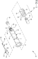
- Fig. 1 is an exploded perspective view of a syringe assembly in accordance with the subject invention.
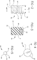
- Fig. 2 is a side elevational view of the plunger stopper shown in Fig. 1.
- Fig. 3 is a cross-sectional view taken along line 3-3 in Fig. 2.
- Fig. 4 is an end elevational view of the plunger stopper shown in Figs. 2 and 3.
- Fig. 5 is an end elevational view similar to Fig. 4 but showing an alternate configuration for the distal end of the plunger stopper.
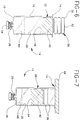
- Fig. 6 is a side elevational view of the syringe assembly in a first operational condition.
- Fig. 7 is a side elevational view of the syringe assembly after lyophilizing and stoppering.
- Fig. 8 is a side elevational view similar to Figs. 6 and 7, but showing the syringe assembly after return to atmospheric pressure.
- Fig. 9 is a side elevational view similar to Figs. 6-8, but showing the syringe assembly during reconstitution of the lyophilized medication.
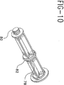
- Fig. 10 is an alternative plunger rod construction for use in the syringe assembly.
- Syringe assembly 10 in accordance with the subject invention is identified generally by the numeral 10 in Fig. 1.
- Syringe assembly 10 includes a syringe barrel 12 having an open proximal end 14, a distal end 16 and a substantially cylindrical side wall 18 extending therebetween.
- the barrel has a uniform circularly shaped cross-section without any deformations in the side wall which allow liquid to flow around stoppers in the barrel.
- Chamber wall 18 defines a substantially cylindrical fluid receiving chamber 20 of inside diameter "a".
- Distal end 16 of syringe barrel 12 includes an elongate tip 22 having a passage 24 extending axially therethrough and communicating with chamber 20.
- a locking luer type collar 26 concentrically surrounds tip 22, and includes an array of threads for threadedly engaging a needle cannula, as explained further herein.
- the locking luer type collar is desirable for enhancing the connection between the needle and the syringe, syringe barrels without locking luer-type collars are frequently used. Syringe barrels without locking collars rely on frictional engagement between the barrel tip and the inside of a needle hub to hold the needle on the barrel.
- Syringe assembly 10 includes a tip cap 28 formed from an elastomeric or plastic material and dimensioned for sealingly engaging tip 22 of syringe barrel 12.
- the syringe assembly further includes a generally cylindrical plunger stopper 30 with opposed proximal and distal ends 32 and 34 respectively as shown in Figs. 1-4.
- the stopper is made of elastomeric material such as natural rubber, synthetic rubber or thermoplastic elastomers.
- Proximal end 32 of plunger stopper 30 is characterized by a plurality of annular ribs 36 defining an outside diameter "b", which is slightly greater than inside diameter "a" of cylindrical chamber 20 in syringe barrel 12.
- ribs 36 can be placed in sliding fluid-tight engagement with cylindrical chamber wall 18 of syringe barrel 12.
- Proximal end 32 of plunger stopper 30 includes an internally threaded mounting cavity 40 for threadedly receiving a plunger rod as explained herein.
- Distal end 34 of plunger stopper 30 includes at least one vapor passage and in this embodiment it includes a plurality of vapor passages 42 extending proximally from distal end 34.
- the passages may define helical flutes as shown in Figs. 2 and 4.
- distal end 34 may be characterized by a plurality of axially extending ribs 44, as shown in Fig. 5, which define vapor passages 42 therealong.
- the passages extending from distal end 34 of plunger stopper 30 enable an outflow of vapor during lyophilizing processes. The outflow of vapor is further facilitated by a reduced diameter portion 46 intermediate proximal and distal ends 32 and 34.
- a plunger rod 48 includes a threaded distal end 50 which is threadedly engageable in threaded aperture 40 at distal end 32 of plunger stopper 30.
- Plunger rod 48 can be threadedly engaged with plunger stopper 30 after lyophilizing the medication and prior to reconstituting the lyophilized medication. It is within the purview of this invention to include other structures for joining the distal end of the plunger rod and the proximal end of the stopper such as snap-fit arrangement or a bayonet-type fitting.
- the stopper can also include a rigid insert to accept the plunger rod.
- the syringe assembly 10 further includes at least one needle assembly 52.
- Needle assembly 52 includes an elongate needle cannula 54 having a proximal end 56, a distal end 58 and a lumen 60 extending therebetween. Proximal end 56 of needle cannula 54 is securely mounted to a mounting hub 62 which is configured for threaded engagement with luer collar 26 at distal end 16 of syringe barrel 12.
- Syringe assembly 10 is used by sealingly engaging tip cap 28 over tip 22 of syringe barrel 12, and then supporting syringe barrel 12 such that proximal end 14 is gravitationally upward, as shown in Fig. 6.
- the barrel may be supported in the upright position by providing a plate with holes or slots which are larger than the barrel outside diameter but smaller than the finger flange diameter.
- a selected dose of liquid medication 64 is then deposited in chamber 20 of syringe barrel 12.
- Distal end 34 of plunger stopper 30 is then inserted into open proximal end 14 of syringe barrel 12 such that reduced diameter portion 46 of plunger stopper 30 is approximately aligned with distal end 14 of syringe barrel 12.
- vapor passages 42 in plunger stopper 30 enable communication between chamber 20 of syringe barrel 12 and ambient atmosphere surrounding syringe barrel 12.
- the filled and stoppered syringe barrel is then presented to a lyophilizing apparatus to freeze dry medication 64. Lyophilization process or vacuum converts liquid portions of medication 64 into a solid which is subject to a subatmospheric pressure to create a vapor.
- the vapor is drawn from chamber 20 through vapor passages 42 and to regions external of the lyophilizing apparatus. The end result is dry lyophilized medication 65.
- a vacuum is applied to the lyophilizing apparatus to provide at least a partial vacuum both within chamber 20 and in regions of the lyophilizing apparatus external of syringe barrel 12.
- a solid member such as a shelf 66 of the lyophilizing apparatus is lowered into contact with proximal end 32 of plunger stopper 30 to urge ribs 36, at distal end 32 of plunger stopper 30, into sealing engagement with cylindrical chamber wall 18 of the vertically supported syringe barrel 12.
- the lyophilizing apparatus then is returned to atmospheric pressure.
- the higher atmospheric pressure only affects portions of the lyophilizing apparatus external of chamber 20.
- plunger stopper 30 The pressure differential on opposed sides of plunger stopper 30 will cause the plunger stopper to slide distally in syringe barrel 12 and toward lyophilized medication 65, as shown in Fig. 8. This distal movement of plunger stopper 30 will terminate when the pressure between the chamber containing the lyophilized medication 65 and plunger stopper 30 approximately equals the atmospheric pressure external of syringe barrel 12.
- the open proximal end of the barrel may be sealed to prevent contamination of the walls of the chamber 20.
- the sealing can be accomplished with a rubber or plastic plug such as plug 74 which has a boss or projection 76 having a diameter slightly larger than the inside diameter of the chamber. Sealing of the chamber may also be accomplished by additional structure on the plunger rod such as a second stopper-like section on the plunger rod spaced proximally from stopper 30.
- additional structure on the plunger rod such as a second stopper-like section on the plunger rod spaced proximally from stopper 30.
- Plunger rod 78 includes threaded distal end 80 and a central groove having an O-ring 82 which seals the chamber inside diameter while the syringe, containing dry medication, is in storage.
- the syringe barrel with the lyophilized medication 65 sealed therein by tip cap 28 and plunger stopper 30 can then be packaged and shipped for subsequent reconstitution and use.
- Reconstitution is achieved with a diluent 70 as shown in Fig. 9. More particularly, the selected diluent is stored in a container 72 such as a vial, ampule, or any other rigid or flexible reservoir which could be engaged to the barrel tip either directly or through a needle.
- the diluent 70 is accessed by initially threadedly engaging distal end 50 of plunger rod 48 into threaded aperture 40 of plunger stopper 30.
- Tip cap 28 is then removed from tip 22 of syringe barrel 12, and hub 62 of needle cannula assembly 52 is threadedly engaged with luer collar 26 of syringe barrel 22.
- the lumen through needle cannula 54 is placed in communication with passage 24 through tip 22, and hence in communication with lyophilized medication 65 in chamber 20.
- Reconstitution is achieved as shown in Fig. 9, by placing distal end 60 of needle cannula 54 in diluent 70.
- Plunger rod 48 is then moved proximally to draw diluent into chamber 20 for mixing with previously lyophilized medication 65.
- Syringe assembly 10 then can be used substantially in the standard manner by urging plunger rod 48 in a distal direction.
- the needle assembly 52 used for reconstitution of the lyophilized medication can be removed and replaced with a needle cannula more suitable for injection into a patient. Also, as mentioned hereinabove, it is possible to reconstitute the medication by connecting the barrel directly to a liquid reservoir without the use of a needle.
- the distal end of the plunger stopper can have vapor passage configurations other than those described herein.
- the plunger stopper may be unitarily molded from an elastomeric material that is suitably configured for engagement with a plunger rod.
Abstract
Description
- The subject invention relates to a hypodermic syringe and a method or process for efficiently lyophilizing an injectable medication and for subsequently reconstituting the lyophilized medication.
- Pre-filled hypodermic syringes offer many efficiencies. However, many injectable medications degrade rapidly and lose their effectiveness. Refrigeration and special packaging can increase shelf life, but add to cost, complicate storage and offset many efficiencies provided by pre-filled syringes.
- Shelf life can be substantially increased by lyophilizing or freeze drying the injectable medication. The lyophilizing process reduces the liquid medication to a dried powdery or granular form. Lyophilized medication can be stored in the chamber of a hypodermic syringe. Shortly prior to use, the lyophilized medication is mixed with a diluent, and the reconstituted medication can be injected from the same hypodermic syringe in which the lyophilized medication had been stored.
- The prior art includes hypodermic syringes made of glass or plastic having a chamber with a stopper slidably disposed at an intermediate position. Regions of the chamber disposed distally of the stopper are of non-cylindrical shape and define a bypass. A lyophilized medication is stored in the chamber distally of the stopper, while a selected diluent is stored in the chamber proximally of the stopper. A plunger is slidably disposed in fluid-tight engagement with the chamber wall proximally of the diluent. Movement of the plunger in a distal direction urges both the diluent and the stopper toward the lyophilized medication. The stopper eventually will align with the bypass region of the prior art syringe barrel, and further movement of the plunger will cause the diluent to flow through the bypass and into the distal portion of the chamber for mixing with the lyophilized medication. The stopper can be configured to promote a flow pattern of the diluent that will enhance mixing of the diluent with the lyophilized medication. An example of such a hypodermic syringe is shown in U.S. Patent No. 4,599,082.
- The two-component hypodermic syringe assembly described above functions very well. However, it is desired to make improvements. For example, the need for two axial spaced chamber sections along the body of the hypodermic syringe necessitates a longer syringe. The lyophilizing process generally is carried out in the syringe. Thus, the lyophilizing apparatus must be large enough to accommodate the larger syringe. Larger hypodermic syringes and correspondingly larger lyophilizing apparatus are more costly and require more space. Additionally, the need for a non-cylindrical cross-section in the bypass region of the prior art syringe increases costs.
- A lyophilizing syringe assembly in accordance with the subject invention includes a generally cylindrical syringe barrel, usually made of plastic or glass, having an open proximal end, a distal end and a fluid receiving chamber therebetween. The distal end of the syringe barrel defines a tip having a passage extending therethrough and communicating with the chamber. A tip cap is releasably engageable with the tip to seal the passage therethrough. The tip also is configured to releasably receive a needle cannula.
- The syringe assembly further includes a lyophilizing plunger stopper. The plunger stopper is generally cylindrical and has opposed proximal and distal ends. The stopper is preferably molded from an elastomeric material for sealing engagement with the cylindrical walls of the syringe barrel. The proximal end of the plunger stopper is configured for selective engagement with a plunger rod. For example, a recess may be provided with an array of threads for threadedly engaging a threaded plunger rod. The proximal end of the plunger stopper is further configured for sliding fluid-tight engagement with the cylindrical walls of the syringe barrel. For example, proximal portions of the plunger stopper may include a plurality of annular ribs having diameters slightly greater than the inside diameter of the chamber to sealingly engage the cylindrical chamber wall. The distal end of the stopper defines at least one vapor passage to enable an escape of vapor during a lyophilizing process as defined further herein. The vapor passage may be defined by at least one rib or groove extending from the distal end of the plunger stopper to a point intermediate the opposed distal and proximal ends.
- The syringe assembly of the subject invention is employed by attaching the tip cap over the tip of the syringe barrel and depositing a dose of liquid medication in the chamber. The distal end of the plunger stopper then is inserted in the open proximal end of the syringe barrel, such that the vapor passages of the plunger stopper permit fluid flow from the chamber. The syringe barrel is then subjected to a lyophilizing process for freeze drying the liquid portions of the medication in the barrel. The frozen liquid portions of medication are subject to a subatmospheric pressure and then, as a gas or vapor, efficiently drawn through the vapor passages at the distal end of the plunger stopper.
- Upon completion of the lyophilizing process, a vacuum is applied in the lyophilizing apparatus to reduce pressure in the chamber. The proximal end of the plunger stopper then is urged into sealing engagement with the cylindrical walls of the syringe barrel. The process continues by permitting regions surrounding the syringe assembly to return to atmospheric pressure. This higher pressure will cause the plunger stopper to move distally in the syringe barrel and toward the lyophilized medication at the distal end of the chamber.
- The syringe barrel with the lyophilized medication therein can be packaged and shipped in the standard manner. The lyophilized medication will be safely protected between the tip cap that is sealingly engaged over the tip of the syringe barrel and the plunger stopper that is sealingly engaged within the chamber of the syringe barrel.
- The syringe assembly and lyophilized medication can be used by engaging a plunger rod with the engagement means at the proximal end of the plunger stopper. The tip cap can then be removed from the tip of the syringe barrel and a needle cannula can be mounted thereto. The distal tip of the needle cannula then can be inserted into a vial or ampule with an appropriate diluent, and a proximally directed force can be exerted on the plunger rod to move the plunger stopper in a proximal direction. The low pressure created by this proximal movement will cause the diluent to flow through the needle cannula and into the chamber for mixing with the lyophilized medication.
- The syringe assembly of the subject invention does not require a bypass in the syringe barrel, and hence can use the less expensive conventional cylindrical syringe barrel. Additionally, by using a diluent from a separate vial or ampule, a separate space for a diluent is not required in the syringe barrel. Thus, the syringe barrel can be substantially shorter than prior art two-component syringe assemblies, and a smaller lyophilizing apparatus also can be used. The subject syringe assembly also requires only one plunger stopper. Hence, further reductions in the size of the syringe barrel can be achieved, along with corresponding cost savings due to the use of a single plunger stopper and a smaller syringe barrel.
- Fig. 1 is an exploded perspective view of a syringe assembly in accordance with the subject invention.
- Fig. 2 is a side elevational view of the plunger stopper shown in Fig. 1.
- Fig. 3 is a cross-sectional view taken along line 3-3 in Fig. 2.
- Fig. 4 is an end elevational view of the plunger stopper shown in Figs. 2 and 3.
- Fig. 5 is an end elevational view similar to Fig. 4 but showing an alternate configuration for the distal end of the plunger stopper.
- Fig. 6 is a side elevational view of the syringe assembly in a first operational condition.
- Fig. 7 is a side elevational view of the syringe assembly after lyophilizing and stoppering.
- Fig. 8 is a side elevational view similar to Figs. 6 and 7, but showing the syringe assembly after return to atmospheric pressure.
- Fig. 9 is a side elevational view similar to Figs. 6-8, but showing the syringe assembly during reconstitution of the lyophilized medication.
- Fig. 10 is an alternative plunger rod construction for use in the syringe assembly.
- A syringe assembly in accordance with the subject invention is identified generally by the numeral 10 in Fig. 1.
Syringe assembly 10 includes asyringe barrel 12 having an openproximal end 14, adistal end 16 and a substantiallycylindrical side wall 18 extending therebetween. The barrel has a uniform circularly shaped cross-section without any deformations in the side wall which allow liquid to flow around stoppers in the barrel.Chamber wall 18 defines a substantially cylindricalfluid receiving chamber 20 of inside diameter "a".Distal end 16 ofsyringe barrel 12 includes anelongate tip 22 having apassage 24 extending axially therethrough and communicating withchamber 20. A lockingluer type collar 26 concentrically surroundstip 22, and includes an array of threads for threadedly engaging a needle cannula, as explained further herein. Although the locking luer type collar is desirable for enhancing the connection between the needle and the syringe, syringe barrels without locking luer-type collars are frequently used. Syringe barrels without locking collars rely on frictional engagement between the barrel tip and the inside of a needle hub to hold the needle on the barrel. -
Syringe assembly 10 includes atip cap 28 formed from an elastomeric or plastic material and dimensioned for sealingly engagingtip 22 ofsyringe barrel 12. - The syringe assembly further includes a generally
cylindrical plunger stopper 30 with opposed proximal anddistal ends Proximal end 32 ofplunger stopper 30 is characterized by a plurality ofannular ribs 36 defining an outside diameter "b", which is slightly greater than inside diameter "a" ofcylindrical chamber 20 insyringe barrel 12. Thus,ribs 36 can be placed in sliding fluid-tight engagement withcylindrical chamber wall 18 ofsyringe barrel 12.Proximal end 32 ofplunger stopper 30 includes an internally threaded mountingcavity 40 for threadedly receiving a plunger rod as explained herein. -
Distal end 34 ofplunger stopper 30 includes at least one vapor passage and in this embodiment it includes a plurality ofvapor passages 42 extending proximally fromdistal end 34. The passages may define helical flutes as shown in Figs. 2 and 4. Alternatively,distal end 34 may be characterized by a plurality of axially extendingribs 44, as shown in Fig. 5, which definevapor passages 42 therealong. The passages extending fromdistal end 34 ofplunger stopper 30 enable an outflow of vapor during lyophilizing processes. The outflow of vapor is further facilitated by a reduceddiameter portion 46 intermediate proximal anddistal ends - Returning to Fig. 1, a
plunger rod 48 includes a threadeddistal end 50 which is threadedly engageable in threadedaperture 40 atdistal end 32 ofplunger stopper 30.Plunger rod 48 can be threadedly engaged withplunger stopper 30 after lyophilizing the medication and prior to reconstituting the lyophilized medication. It is within the purview of this invention to include other structures for joining the distal end of the plunger rod and the proximal end of the stopper such as snap-fit arrangement or a bayonet-type fitting. The stopper can also include a rigid insert to accept the plunger rod. - The
syringe assembly 10 further includes at least oneneedle assembly 52.Needle assembly 52 includes anelongate needle cannula 54 having aproximal end 56, adistal end 58 and alumen 60 extending therebetween.Proximal end 56 ofneedle cannula 54 is securely mounted to a mountinghub 62 which is configured for threaded engagement withluer collar 26 atdistal end 16 ofsyringe barrel 12. -
Syringe assembly 10 is used by sealingly engagingtip cap 28 overtip 22 ofsyringe barrel 12, and then supportingsyringe barrel 12 such thatproximal end 14 is gravitationally upward, as shown in Fig. 6. For example, the barrel may be supported in the upright position by providing a plate with holes or slots which are larger than the barrel outside diameter but smaller than the finger flange diameter. A selected dose ofliquid medication 64 is then deposited inchamber 20 ofsyringe barrel 12.Distal end 34 ofplunger stopper 30 is then inserted into openproximal end 14 ofsyringe barrel 12 such that reduceddiameter portion 46 ofplunger stopper 30 is approximately aligned withdistal end 14 ofsyringe barrel 12. Thusvapor passages 42 inplunger stopper 30 enable communication betweenchamber 20 ofsyringe barrel 12 and ambient atmosphere surroundingsyringe barrel 12. The filled and stoppered syringe barrel is then presented to a lyophilizing apparatus to freezedry medication 64. Lyophilization process or vacuum converts liquid portions ofmedication 64 into a solid which is subject to a subatmospheric pressure to create a vapor. The vapor is drawn fromchamber 20 throughvapor passages 42 and to regions external of the lyophilizing apparatus. The end result is drylyophilized medication 65. - A vacuum is applied to the lyophilizing apparatus to provide at least a partial vacuum both within
chamber 20 and in regions of the lyophilizing apparatus external ofsyringe barrel 12. Next, as shown in Fig. 7, a solid member such as ashelf 66 of the lyophilizing apparatus is lowered into contact withproximal end 32 ofplunger stopper 30 to urgeribs 36, atdistal end 32 ofplunger stopper 30, into sealing engagement withcylindrical chamber wall 18 of the vertically supportedsyringe barrel 12. The lyophilizing apparatus then is returned to atmospheric pressure. However, the higher atmospheric pressure only affects portions of the lyophilizing apparatus external ofchamber 20. The pressure differential on opposed sides ofplunger stopper 30 will cause the plunger stopper to slide distally insyringe barrel 12 and towardlyophilized medication 65, as shown in Fig. 8. This distal movement ofplunger stopper 30 will terminate when the pressure between the chamber containing thelyophilized medication 65 andplunger stopper 30 approximately equals the atmospheric pressure external ofsyringe barrel 12. - After the process is complete, the open proximal end of the barrel may be sealed to prevent contamination of the walls of the
chamber 20. The sealing can be accomplished with a rubber or plastic plug such asplug 74 which has a boss orprojection 76 having a diameter slightly larger than the inside diameter of the chamber. Sealing of the chamber may also be accomplished by additional structure on the plunger rod such as a second stopper-like section on the plunger rod spaced proximally fromstopper 30. Such a plunger rod is illustrated in Fig. 10.Plunger rod 78 includes threadeddistal end 80 and a central groove having an O-ring 82 which seals the chamber inside diameter while the syringe, containing dry medication, is in storage. - The syringe barrel with the
lyophilized medication 65 sealed therein bytip cap 28 andplunger stopper 30 can then be packaged and shipped for subsequent reconstitution and use. Reconstitution is achieved with a diluent 70 as shown in Fig. 9. More particularly, the selected diluent is stored in acontainer 72 such as a vial, ampule, or any other rigid or flexible reservoir which could be engaged to the barrel tip either directly or through a needle. The diluent 70 is accessed by initially threadedly engagingdistal end 50 ofplunger rod 48 into threadedaperture 40 ofplunger stopper 30.Tip cap 28 is then removed fromtip 22 ofsyringe barrel 12, andhub 62 ofneedle cannula assembly 52 is threadedly engaged withluer collar 26 ofsyringe barrel 22. Thus, the lumen throughneedle cannula 54 is placed in communication withpassage 24 throughtip 22, and hence in communication withlyophilized medication 65 inchamber 20. Reconstitution is achieved as shown in Fig. 9, by placingdistal end 60 ofneedle cannula 54 indiluent 70.Plunger rod 48 is then moved proximally to draw diluent intochamber 20 for mixing with previously lyophilizedmedication 65.Syringe assembly 10 then can be used substantially in the standard manner by urgingplunger rod 48 in a distal direction. If necessary, theneedle assembly 52 used for reconstitution of the lyophilized medication can be removed and replaced with a needle cannula more suitable for injection into a patient. Also, as mentioned hereinabove, it is possible to reconstitute the medication by connecting the barrel directly to a liquid reservoir without the use of a needle. - While the invention has been described with respect to a preferred embodiment, it is apparent that various changes can be made without departing from the scope of the invention as defined by the appended claims. For example, the distal end of the plunger stopper can have vapor passage configurations other than those described herein. Additionally, the plunger stopper may be unitarily molded from an elastomeric material that is suitably configured for engagement with a plunger rod.
Claims (10)
- A syringe assembly for lyophilizing and subsequently reconstituting an injectable medication, said syringe assembly comprising:
a syringe barrel having an open proximal end, a distal end and a substantially cylindrical chamber wall extending therebetween to define a fluid receiving chamber, a passage extending through said distal end and communicating with said chamber;
means for releasably sealing said passage to isolate said chamber from the environment;
a plunger stopper having opposed proximal and distal ends, at least said distal end of said plunger stopper being disposed in said chamber, at least one vapor passage defined in said plunger stopper and extending from said distal end thereof terminating at a location between said ends of said stopper, said proximal end of said plunger stopper being dimensioned for sliding fluid-tight sealing engagement with said cylindrical chamber wall so that said distal end of said plunger stopper can be engaged in said chamber with said vapor passage enabling escape of vapor from said chamber during lyophilization of said injectable medication, and said proximal end being dimensioned so that said proximal end of said plunger stopper can be urged into sliding fluid-tight engagement with said cylindrical wall of said chamber upon completion of said lyophilization for sealing the lyophilized medication in said chamber, and said plunger stopper subsequently can be urged proximally for reconstituting said lyophilized medication into an injectable form; and
mounting means defined at said proximal end of said plunger stopper for engaging a plunger rod. - The syringe assembly of Claim 1, wherein said mounting means of said plunger stopper includes a threaded cavity.
- The syringe assembly of Claim 1, further comprising an elongate plunger rod having proximal and distal ends, said plunger rod selectively engageable with said mounting means of said plunger stopper, said plunger rod being dimensioned to project to locations proximally of said proximal end of said syringe barrel.
- The syringe assembly of Claim 1, wherein said at least one vapor passage includes a plurality of flutes.
- The assembly of Claim 4 wherein said flutes are helically oriented.
- The syringe assembly of Claim 1, wherein said vapor passage is defined by a plurality of axially extending ribs.
- The syringe assembly of Claim 1 wherein said distal end of said barrel includes a tip projecting distally therefrom and surrounding said passageway.
- The syringe assembly of Claim 1 further including sealing means on said plunger rod positioned proximally from said distal end of said plunger rod for sealing said chamber from contamination.
- The syringe assembly of Claim 8 wherein said sealing means includes a resilient O-ring around said plunger rod.
- The syringe assembly of Claim 1 further including a plug releasably engaging the open proximal end of the barrel to seal and protect the portion of the barrel chamber between the plunger stopper and the open proximal end of the barrel.
Applications Claiming Priority (2)
| Application Number | Priority Date | Filing Date | Title |
|---|---|---|---|
| US18723394A | 1994-01-25 | 1994-01-25 | |
| US187233 | 1994-01-25 |
Publications (3)
| Publication Number | Publication Date |
|---|---|
| EP0664137A2 true EP0664137A2 (en) | 1995-07-26 |
| EP0664137A3 EP0664137A3 (en) | 1995-08-30 |
| EP0664137B1 EP0664137B1 (en) | 1999-03-31 |
Family
ID=22688129
Family Applications (1)
| Application Number | Title | Priority Date | Filing Date |
|---|---|---|---|
| EP95300306A Expired - Lifetime EP0664137B1 (en) | 1994-01-25 | 1995-01-18 | Syringe and method for lyophilizing and reconstituting injectable medication |
Country Status (4)
| Country | Link |
|---|---|
| US (1) | US5752940A (en) |
| EP (1) | EP0664137B1 (en) |
| JP (1) | JP2738513B2 (en) |
| DE (2) | DE664137T1 (en) |
Cited By (8)
| Publication number | Priority date | Publication date | Assignee | Title |
|---|---|---|---|---|
| EP0815886A2 (en) * | 1996-06-28 | 1998-01-07 | Becton, Dickinson and Company | A stopper assembly having bypass for use in a multi-chamber syringe barrel |
| US5791466A (en) * | 1995-09-07 | 1998-08-11 | Elan Medical Technologies Limited | Medicament conversion system |
| WO2000038615A1 (en) * | 1998-12-25 | 2000-07-06 | Torii Pharmaceutical Co., Ltd. | Medicine container and syringe |
| WO2011022607A1 (en) * | 2009-08-21 | 2011-02-24 | Becton Dickinson France Sas | Syringe assembly with pivoting plunger and integral tip guard |
| US8814823B2 (en) | 2004-10-25 | 2014-08-26 | Pharma Consult Ges.M.B.H. & Co Nfg Kg | Method and devices for lyophilizing, reconstituting, and administering a reconstituted agent |
| US9003676B2 (en) | 1998-11-12 | 2015-04-14 | Tolmar Therapeutics, Inc. | Method for lyophilizing an active agent |
| US10794632B2 (en) | 2016-02-05 | 2020-10-06 | Tolmar Therapeutics, Inc. | Vented cover plate for an array of syringes |
| USD908916S1 (en) | 2018-06-19 | 2021-01-26 | Tolmar Therapeutics, Inc. | Syringe restrictor plate |
Families Citing this family (59)
| Publication number | Priority date | Publication date | Assignee | Title |
|---|---|---|---|---|
| FI102642B (en) * | 1996-06-19 | 1999-01-15 | Orion Diagnostica Oy | Plug for a reaction vessel or equivalent |
| JPH11155951A (en) * | 1997-12-01 | 1999-06-15 | Kaken Pharmaceut Co Ltd | Decompression syringe and manufacture thereof |
| US6527738B1 (en) * | 1999-04-30 | 2003-03-04 | Prismedical Corporation | Drug delivery pack |
| JP4721314B2 (en) * | 1999-07-15 | 2011-07-13 | ブラッコ インターナショナル ビーヴィ | Plunger for syringe |
| DE19953978A1 (en) * | 1999-11-10 | 2001-12-06 | Lucien C Olivier | Syringe for the medical application of liquids, e.g. B. medication |
| DE10057616B4 (en) * | 2000-11-21 | 2006-09-14 | Stryker Trauma Gmbh | Method for mixing and applying flowable bone cement and bone cement mixing device |
| ATE354338T1 (en) * | 2001-03-27 | 2007-03-15 | Lilly Co Eli | KIT WITH A SIDE-HOLE SYRINGE NEEDLE FOR PREPARING A MEDICATION IN AN INJECTION PEN CARTRIDGE |
| US6494866B1 (en) | 2001-04-05 | 2002-12-17 | Owens-Illinois Closure Inc. | Syringe plunger rod and method of manufacture |
| AU2002309676A1 (en) | 2001-05-04 | 2002-11-18 | Prismedical Corporation | Dual chamber dissolution container with passive agitation |
| JP4681795B2 (en) | 2001-05-18 | 2011-05-11 | デカ・プロダクツ・リミテッド・パートナーシップ | Fluid pump infusion set |
| US8034026B2 (en) | 2001-05-18 | 2011-10-11 | Deka Products Limited Partnership | Infusion pump assembly |
| US20050150915A1 (en) * | 2004-01-09 | 2005-07-14 | Ronald Baretela | Food dispenser plunger system |
| US20080234632A1 (en) * | 2004-03-23 | 2008-09-25 | Mitsuru Hasegawa | Pre-Filled Syringe |
| US20050251096A1 (en) * | 2004-05-10 | 2005-11-10 | George Armstrong | Syringe assembly with improved cap and luer connector |
| ES2906559T3 (en) | 2004-09-10 | 2022-04-19 | Becton Dickinson Co | Patch type infusion device |
| US8425453B2 (en) | 2004-12-30 | 2013-04-23 | Integrity Bio, Inc. | Compact medication reconstitution device and method |
| US20060157507A1 (en) * | 2004-12-30 | 2006-07-20 | Chang Byeong S | Multi-functional container closure delivery system |
| US20060144869A1 (en) * | 2004-12-30 | 2006-07-06 | Chang Byeong S | Container closure delivery system |
| US7959600B2 (en) * | 2004-12-30 | 2011-06-14 | Byeong S. Chang | Container closure delivery system |
| FR2885512B1 (en) * | 2005-05-10 | 2007-08-10 | Biocoral Inc | SYRINGE FOR BIO-MATERIAL |
| US7575131B2 (en) * | 2005-07-13 | 2009-08-18 | Ethicon, Inc. | Multi-component delivery system |
| US8852164B2 (en) | 2006-02-09 | 2014-10-07 | Deka Products Limited Partnership | Method and system for shape-memory alloy wire control |
| US11497846B2 (en) | 2006-02-09 | 2022-11-15 | Deka Products Limited Partnership | Patch-sized fluid delivery systems and methods |
| DE602007013723D1 (en) | 2006-02-09 | 2011-05-19 | Deka Products Lp | SYSTEMS FOR DISPENSING FLUIDS IN PATCH SIZE |
| US11478623B2 (en) | 2006-02-09 | 2022-10-25 | Deka Products Limited Partnership | Infusion pump assembly |
| US11364335B2 (en) | 2006-02-09 | 2022-06-21 | Deka Products Limited Partnership | Apparatus, system and method for fluid delivery |
| CA2834152C (en) | 2006-05-25 | 2016-07-05 | Bayer Healthcare Llc | Reconstitution device |
| ES2704011T3 (en) * | 2006-08-31 | 2019-03-13 | Meridian Medical Tech Inc | Vortex device for a drug delivery system |
| US8900188B2 (en) | 2007-12-31 | 2014-12-02 | Deka Products Limited Partnership | Split ring resonator antenna adapted for use in wirelessly controlled medical device |
| CA2919786C (en) | 2007-12-31 | 2019-10-22 | Deka Products Limited Partnership | Infusion pump assembly |
| US10080704B2 (en) | 2007-12-31 | 2018-09-25 | Deka Products Limited Partnership | Apparatus, system and method for fluid delivery |
| US9456955B2 (en) | 2007-12-31 | 2016-10-04 | Deka Products Limited Partnership | Apparatus, system and method for fluid delivery |
| WO2009088956A2 (en) | 2007-12-31 | 2009-07-16 | Deka Products Limited Partnership | Infusion pump assembly |
| US10188787B2 (en) | 2007-12-31 | 2019-01-29 | Deka Products Limited Partnership | Apparatus, system and method for fluid delivery |
| US8881774B2 (en) | 2007-12-31 | 2014-11-11 | Deka Research & Development Corp. | Apparatus, system and method for fluid delivery |
| WO2010031059A2 (en) | 2008-09-15 | 2010-03-18 | Deka Products Limited Partnership | Systems and methods for fluid delivery |
| US8066672B2 (en) | 2008-10-10 | 2011-11-29 | Deka Products Limited Partnership | Infusion pump assembly with a backup power supply |
| US9180245B2 (en) | 2008-10-10 | 2015-11-10 | Deka Products Limited Partnership | System and method for administering an infusible fluid |
| US8016789B2 (en) | 2008-10-10 | 2011-09-13 | Deka Products Limited Partnership | Pump assembly with a removable cover assembly |
| US8708376B2 (en) | 2008-10-10 | 2014-04-29 | Deka Products Limited Partnership | Medium connector |
| US8267892B2 (en) | 2008-10-10 | 2012-09-18 | Deka Products Limited Partnership | Multi-language / multi-processor infusion pump assembly |
| US8223028B2 (en) | 2008-10-10 | 2012-07-17 | Deka Products Limited Partnership | Occlusion detection system and method |
| US9149581B2 (en) | 2009-03-09 | 2015-10-06 | Glucago Llc | Compact device for rapidly mixing and delivering substances to a patient |
| WO2011008966A2 (en) | 2009-07-15 | 2011-01-20 | Deka Products Limited Partnership | Apparatus, systems and methods for an infusion pump assembly |
| JP4638553B1 (en) * | 2010-08-09 | 2011-02-23 | 株式会社アルテ | Manufacturing method and front stopper of two-chamber syringe |
| WO2013134519A2 (en) | 2012-03-07 | 2013-09-12 | Deka Products Limited Partnership | Apparatus, system and method for fluid delivery |
| US11116892B2 (en) | 2012-08-28 | 2021-09-14 | Osprey Medical, Inc. | Medium injection diversion and measurement |
| US10413677B2 (en) | 2012-08-28 | 2019-09-17 | Osprey Medical, Inc. | Volume monitoring device |
| US11219719B2 (en) | 2012-08-28 | 2022-01-11 | Osprey Medical, Inc. | Volume monitoring systems |
| US20150202386A1 (en) * | 2012-08-28 | 2015-07-23 | Osprey Medical, Inc. | Volume monitoring device utilizing hall sensor-based systems |
| US9125995B2 (en) | 2012-12-05 | 2015-09-08 | Glucago Llc | Reconstitution devices |
| USD750774S1 (en) * | 2013-04-19 | 2016-03-01 | Transcoject Gmbh | Syringe plunger |
| EP3016629B1 (en) | 2013-07-03 | 2023-12-20 | DEKA Products Limited Partnership | Apparatus and system for fluid delivery |
| WO2015031677A1 (en) * | 2013-08-30 | 2015-03-05 | Glucago Llc D/B/A Lyogo | Plunger and plunger valve for drug delivery |
| US10201692B2 (en) | 2014-09-09 | 2019-02-12 | Byeong Seon Chang | Solution delivery device and method |
| KR101672716B1 (en) * | 2015-08-24 | 2016-11-16 | 경상대학교산학협력단 | Mechanical syring assembly unit with patterned surface for mixing improvement |
| WO2019209963A1 (en) | 2018-04-24 | 2019-10-31 | Deka Products Limited Partnership | Apparatus and system for fluid delivery |
| EP3927396A1 (en) * | 2019-02-22 | 2021-12-29 | Credence Medsystems, Inc. | System and method for safety syringe |
| US11499841B2 (en) | 2019-04-12 | 2022-11-15 | Osprey Medical, Inc. | Energy-efficient position determining with multiple sensors |
Citations (5)
| Publication number | Priority date | Publication date | Assignee | Title |
|---|---|---|---|---|
| US4599082A (en) * | 1984-08-13 | 1986-07-08 | Becton, Dickinson And Company | Two-component syringe assembly |
| US4690154A (en) * | 1985-06-03 | 1987-09-01 | Timothy Woodford | Vented syringe |
| EP0302248A1 (en) * | 1987-07-21 | 1989-02-08 | WASSERBURGER ARZNEIMITTELWERK DR. MADAUS GMBH & CO. KG | Injection syringe for medical purposes |
| GB2252951A (en) * | 1991-02-15 | 1992-08-26 | Pasteur Merieux Serums Vacc | Packaging freeze dried vaccine in syringes |
| WO1993014798A1 (en) * | 1992-01-31 | 1993-08-05 | Sherwood Medical Company | Medical device with sterile fluid pathway |
Family Cites Families (9)
| Publication number | Priority date | Publication date | Assignee | Title |
|---|---|---|---|---|
| US3052240A (en) * | 1959-01-29 | 1962-09-04 | Silver | Disposable hypodermic syringe |
| US3016896A (en) * | 1960-01-26 | 1962-01-16 | Wilton E Van Sickle | Disposable hypodermic syringe |
| US3164303A (en) * | 1961-12-04 | 1965-01-05 | Semco Res Inc | Storage and mixing cartridge |
| US3330281A (en) * | 1964-08-21 | 1967-07-11 | Upjohn Co | Combination syringe and vial mixing container |
| US3330282A (en) * | 1964-08-21 | 1967-07-11 | Upjohn Co | Combination syringe and vial mixing container |
| US3901402A (en) * | 1973-03-14 | 1975-08-26 | Becton Dickinson Co | Stopper-piston |
| FR2508341B1 (en) * | 1981-06-29 | 1986-10-31 | Dupont Philippe | DEVICE FOR THE TERM MIXING OF TWO OR MORE COMPONENTS |
| US4613326A (en) * | 1985-07-12 | 1986-09-23 | Becton, Dickinson And Company | Two-component medication syringe assembly |
| US5236420A (en) * | 1992-06-01 | 1993-08-17 | Pfleger Frederick W | Bypass, pressurizing piston for chambers |
-
1995
- 1995-01-18 EP EP95300306A patent/EP0664137B1/en not_active Expired - Lifetime
- 1995-01-18 DE DE0664137T patent/DE664137T1/en active Pending
- 1995-01-18 DE DE69508629T patent/DE69508629T2/en not_active Expired - Lifetime
- 1995-01-25 JP JP7009727A patent/JP2738513B2/en not_active Expired - Lifetime
-
1996
- 1996-04-08 US US08/628,973 patent/US5752940A/en not_active Expired - Lifetime
Patent Citations (5)
| Publication number | Priority date | Publication date | Assignee | Title |
|---|---|---|---|---|
| US4599082A (en) * | 1984-08-13 | 1986-07-08 | Becton, Dickinson And Company | Two-component syringe assembly |
| US4690154A (en) * | 1985-06-03 | 1987-09-01 | Timothy Woodford | Vented syringe |
| EP0302248A1 (en) * | 1987-07-21 | 1989-02-08 | WASSERBURGER ARZNEIMITTELWERK DR. MADAUS GMBH & CO. KG | Injection syringe for medical purposes |
| GB2252951A (en) * | 1991-02-15 | 1992-08-26 | Pasteur Merieux Serums Vacc | Packaging freeze dried vaccine in syringes |
| WO1993014798A1 (en) * | 1992-01-31 | 1993-08-05 | Sherwood Medical Company | Medical device with sterile fluid pathway |
Cited By (17)
| Publication number | Priority date | Publication date | Assignee | Title |
|---|---|---|---|---|
| US5791466A (en) * | 1995-09-07 | 1998-08-11 | Elan Medical Technologies Limited | Medicament conversion system |
| EP0815886A3 (en) * | 1996-06-28 | 1998-01-28 | Becton, Dickinson and Company | A stopper assembly having bypass for use in a multi-chamber syringe barrel |
| US5865798A (en) * | 1996-06-28 | 1999-02-02 | Becton Dickinson France, S.A. | Stopper assembly having bypass features for use in a multi-chamber syringe barrel |
| US5899881A (en) * | 1996-06-28 | 1999-05-04 | Grimard; Jean Pierre | Stopper assembly having bypass features for use in a multi-chamber syringe barrel |
| EP0815886A2 (en) * | 1996-06-28 | 1998-01-07 | Becton, Dickinson and Company | A stopper assembly having bypass for use in a multi-chamber syringe barrel |
| US9003676B2 (en) | 1998-11-12 | 2015-04-14 | Tolmar Therapeutics, Inc. | Method for lyophilizing an active agent |
| WO2000038615A1 (en) * | 1998-12-25 | 2000-07-06 | Torii Pharmaceutical Co., Ltd. | Medicine container and syringe |
| EP3042674A1 (en) | 2003-03-17 | 2016-07-13 | Tolmar Therapeutics, Inc. | Method for lyophilizing an active agent |
| US8814823B2 (en) | 2004-10-25 | 2014-08-26 | Pharma Consult Ges.M.B.H. & Co Nfg Kg | Method and devices for lyophilizing, reconstituting, and administering a reconstituted agent |
| JP2013502287A (en) * | 2009-08-21 | 2013-01-24 | ベクトン ディキンソン フランス | Syringe assembly with swivel plunger and integral tip guard |
| CN102573959A (en) * | 2009-08-21 | 2012-07-11 | 贝克顿迪金森法国两合公司 | Syringe assembly with pivoting plunger and integral tip guard |
| CN102573959B (en) * | 2009-08-21 | 2015-07-22 | 贝克顿迪金森法国两合公司 | Syringe assembly with pivoting plunger and integral tip guard |
| WO2011022607A1 (en) * | 2009-08-21 | 2011-02-24 | Becton Dickinson France Sas | Syringe assembly with pivoting plunger and integral tip guard |
| US9821119B2 (en) | 2009-08-21 | 2017-11-21 | Becton Dickinson France | Syringe assembly with pivoting plunger and integral tip guard |
| US10610647B2 (en) | 2009-08-21 | 2020-04-07 | Becton Dickinson France | Syringe assembly with pivoting plunger and integral tip guard |
| US10794632B2 (en) | 2016-02-05 | 2020-10-06 | Tolmar Therapeutics, Inc. | Vented cover plate for an array of syringes |
| USD908916S1 (en) | 2018-06-19 | 2021-01-26 | Tolmar Therapeutics, Inc. | Syringe restrictor plate |
Also Published As
| Publication number | Publication date |
|---|---|
| DE69508629T2 (en) | 1999-10-14 |
| JP2738513B2 (en) | 1998-04-08 |
| DE69508629D1 (en) | 1999-05-06 |
| US5752940A (en) | 1998-05-19 |
| DE664137T1 (en) | 1996-02-15 |
| EP0664137B1 (en) | 1999-03-31 |
| JPH07213609A (en) | 1995-08-15 |
| EP0664137A3 (en) | 1995-08-30 |
Similar Documents
| Publication | Publication Date | Title |
|---|---|---|
| EP0664137B1 (en) | Syringe and method for lyophilizing and reconstituting injectable medication | |
| US5489266A (en) | Syringe assembly and method for lyophilizing and reconstituting injectable medication | |
| US4668223A (en) | Syringe | |
| JP2801207B2 (en) | Syringe and method of assembling syringe | |
| US4613326A (en) | Two-component medication syringe assembly | |
| EP0340880B1 (en) | Syringe | |
| US4599082A (en) | Two-component syringe assembly | |
| US5454786A (en) | Cartridge assembly for a lyophilized compound forming a disposable portion of an injector pen and method for same | |
| US6378576B2 (en) | Vial transferset and method | |
| EP0295337B1 (en) | Two compartment syringe and method of manufacturing | |
| US4581015A (en) | Multimedication syringe | |
| KR19980079299A (en) | Cannula Sealed Seal Assembly | |
| JP2009504523A (en) | Dual chamber container without bypass | |
| US6626870B1 (en) | Stoppering method to maintain sterility | |
| GB2210268A (en) | Syringe system | |
| CA1334070C (en) | Syringe |
Legal Events
| Date | Code | Title | Description |
|---|---|---|---|
| PUAI | Public reference made under article 153(3) epc to a published international application that has entered the european phase |
Free format text: ORIGINAL CODE: 0009012 |
|
| PUAL | Search report despatched |
Free format text: ORIGINAL CODE: 0009013 |
|
| AK | Designated contracting states |
Kind code of ref document: A2 Designated state(s): DE FR GB IT |
|
| AK | Designated contracting states |
Kind code of ref document: A3 Designated state(s): DE FR GB IT |
|
| ITCL | It: translation for ep claims filed |
Representative=s name: STUDIO SAMA PATENTES |
|
| EL | Fr: translation of claims filed | ||
| 17P | Request for examination filed |
Effective date: 19951024 |
|
| DET | De: translation of patent claims | ||
| 17Q | First examination report despatched |
Effective date: 19970613 |
|
| GRAG | Despatch of communication of intention to grant |
Free format text: ORIGINAL CODE: EPIDOS AGRA |
|
| GRAG | Despatch of communication of intention to grant |
Free format text: ORIGINAL CODE: EPIDOS AGRA |
|
| GRAH | Despatch of communication of intention to grant a patent |
Free format text: ORIGINAL CODE: EPIDOS IGRA |
|
| GRAH | Despatch of communication of intention to grant a patent |
Free format text: ORIGINAL CODE: EPIDOS IGRA |
|
| GRAA | (expected) grant |
Free format text: ORIGINAL CODE: 0009210 |
|
| AK | Designated contracting states |
Kind code of ref document: B1 Designated state(s): DE FR GB IT |
|
| PG25 | Lapsed in a contracting state [announced via postgrant information from national office to epo] |
Ref country code: IT Free format text: LAPSE BECAUSE OF FAILURE TO SUBMIT A TRANSLATION OF THE DESCRIPTION OR TO PAY THE FEE WITHIN THE PRE;WARNING: LAPSES OF ITALIAN PATENTS WITH EFFECTIVE DATE BEFORE 2007 MAY HAVE OCCURRED AT ANY TIME BEFORE 2007. THE CORRECT EFFECTIVE DATE MAY BE DIFFERENT FROM THE ONE RECORDED.SCRIBED TIME-LIMIT Effective date: 19990331 |
|
| REF | Corresponds to: |
Ref document number: 69508629 Country of ref document: DE Date of ref document: 19990506 |
|
| ET | Fr: translation filed | ||
| PG25 | Lapsed in a contracting state [announced via postgrant information from national office to epo] |
Ref country code: GB Free format text: LAPSE BECAUSE OF NON-PAYMENT OF DUE FEES Effective date: 20000118 |
|
| PLBE | No opposition filed within time limit |
Free format text: ORIGINAL CODE: 0009261 |
|
| STAA | Information on the status of an ep patent application or granted ep patent |
Free format text: STATUS: NO OPPOSITION FILED WITHIN TIME LIMIT |
|
| 26N | No opposition filed | ||
| GBPC | Gb: european patent ceased through non-payment of renewal fee |
Effective date: 20000118 |
|
| PGFP | Annual fee paid to national office [announced via postgrant information from national office to epo] |
Ref country code: DE Payment date: 20140129 Year of fee payment: 20 |
|
| PGFP | Annual fee paid to national office [announced via postgrant information from national office to epo] |
Ref country code: FR Payment date: 20140117 Year of fee payment: 20 |
|
| REG | Reference to a national code |
Ref country code: DE Ref legal event code: R071 Ref document number: 69508629 Country of ref document: DE |