EP0666631A2 - Field bus power supply system - Google Patents
Field bus power supply system Download PDFInfo
- Publication number
- EP0666631A2 EP0666631A2 EP95250024A EP95250024A EP0666631A2 EP 0666631 A2 EP0666631 A2 EP 0666631A2 EP 95250024 A EP95250024 A EP 95250024A EP 95250024 A EP95250024 A EP 95250024A EP 0666631 A2 EP0666631 A2 EP 0666631A2
- Authority
- EP
- European Patent Office
- Prior art keywords
- field
- intrinsically safe
- fieldbus
- voltage
- distributor
- Prior art date
- Legal status (The legal status is an assumption and is not a legal conclusion. Google has not performed a legal analysis and makes no representation as to the accuracy of the status listed.)
- Granted
Links
Images


Classifications
-
- H—ELECTRICITY
- H02—GENERATION; CONVERSION OR DISTRIBUTION OF ELECTRIC POWER
- H02H—EMERGENCY PROTECTIVE CIRCUIT ARRANGEMENTS
- H02H9/00—Emergency protective circuit arrangements for limiting excess current or voltage without disconnection
- H02H9/008—Intrinsically safe circuits
-
- H—ELECTRICITY
- H02—GENERATION; CONVERSION OR DISTRIBUTION OF ELECTRIC POWER
- H02J—CIRCUIT ARRANGEMENTS OR SYSTEMS FOR SUPPLYING OR DISTRIBUTING ELECTRIC POWER; SYSTEMS FOR STORING ELECTRIC ENERGY
- H02J1/00—Circuit arrangements for dc mains or dc distribution networks
- H02J1/08—Three-wire systems; Systems having more than three wires
-
- H—ELECTRICITY
- H02—GENERATION; CONVERSION OR DISTRIBUTION OF ELECTRIC POWER
- H02J—CIRCUIT ARRANGEMENTS OR SYSTEMS FOR SUPPLYING OR DISTRIBUTING ELECTRIC POWER; SYSTEMS FOR STORING ELECTRIC ENERGY
- H02J1/00—Circuit arrangements for dc mains or dc distribution networks
- H02J1/14—Balancing the load in a network
-
- G—PHYSICS
- G05—CONTROLLING; REGULATING
- G05B—CONTROL OR REGULATING SYSTEMS IN GENERAL; FUNCTIONAL ELEMENTS OF SUCH SYSTEMS; MONITORING OR TESTING ARRANGEMENTS FOR SUCH SYSTEMS OR ELEMENTS
- G05B2219/00—Program-control systems
- G05B2219/20—Pc systems
- G05B2219/24—Pc safety
- G05B2219/24028—Explosion free control, intrinsically safe
-
- H—ELECTRICITY
- H02—GENERATION; CONVERSION OR DISTRIBUTION OF ELECTRIC POWER
- H02J—CIRCUIT ARRANGEMENTS OR SYSTEMS FOR SUPPLYING OR DISTRIBUTING ELECTRIC POWER; SYSTEMS FOR STORING ELECTRIC ENERGY
- H02J9/00—Circuit arrangements for emergency or stand-by power supply, e.g. for emergency lighting
- H02J9/04—Circuit arrangements for emergency or stand-by power supply, e.g. for emergency lighting in which the distribution system is disconnected from the normal source and connected to a standby source
- H02J9/06—Circuit arrangements for emergency or stand-by power supply, e.g. for emergency lighting in which the distribution system is disconnected from the normal source and connected to a standby source with automatic change-over, e.g. UPS systems
Definitions
- the invention relates to a feed system for a fieldbus in explosion-hazardous process plants.
- Field buses are electrical devices for communication between field devices such as sensors, actuators and transmitters arranged in the field area on the one hand and control and regulation systems arranged in the waiting area on the other hand.
- a fieldbus is usually designed as a two-wire line, which also serves to transmit the power of the connected field devices. Communication takes place in an analog manner via a conventional 0/4 ... 20 mA current loop or digitally, for example by means of FSK modulation or with a combined analog / digital signal transmission.
- Figure 1a shows the structure of a first fieldbus system, which, based on a so-called process-related component, hereinafter referred to as PNK, provides a single two-wire line for communication and supply of the field devices to which the individual field devices are connected.
- PNK process-related component
- Figure 1b shows the structure of a second fieldbus system, in which communication is implemented via an Ex'i 'two-wire line and the individual field devices are supplied via separate supply lines for the auxiliary power. That means that on the one hand a large number of field devices can be connected to a fieldbus, but on the other hand n + 1 line pairs from the control room area to n field devices are to be routed to the field devices.
- the circuits of the required n pairs of feed lines must inevitably be designed in Ex'i' type of protection.
- a third fieldbus system is shown in Figure 1c, which represents a combination of the first and the second fieldbus system, with a plurality of field devices being supplied block by block with an auxiliary energy that can be brought in and fed in separately.
- Several blocks are connected to a fieldbus for communication. However, a large number of line pairs are still required between the waiting area and the blocks of field devices.
- Figure 1d also shows a fourth fieldbus system, in which a two-wire line is sufficient for communication and supplying the field devices, but a safety barrier must be assigned to each field device in order to operate the field device on an Ex'i 'circuit.
- the fieldbus itself is designed as a non-intrinsically safe circuit.
- the safety barriers arranged in the field area are additionally flameproof, 'Ex'd', i.e. provided with mechanically complex, precisely fitting sheathing.
- Each barrier includes means for current limitation, voltage limitation, equipotential bonding and thermal protection for downstream components. So far, the installation of barriers has only been permitted in the non-hazardous area.
- any retrofitting, upgrading or other manipulation of equipment with types of protection Ex'e 'and Ex'd' is only permitted when the device is switched off.
- the PNK When connected, intrinsically safe circuits, the PNK is usually equipped with means for potential isolation and means for limiting current and voltage.
- the invention is therefore based on the object of specifying a supply system for a fieldbus in potentially explosive areas, in which the cabling effort is minimal, which is limited to the use of fewer, structurally simple types of protection and which involves the connection of a large number of field devices and their free manipulation in the sense the protection class intrinsic safety allowed during operation.
- this object is achieved according to the invention in that the means for current and voltage limitation are arranged spatially separated and connected via a non-intrinsically safe circuit.
- a PNK is provided in the waiting area, which is equipped with means for voltage or current limitation and for the galvanically isolated supply of auxiliary energy for the field devices.
- a distributor with one pair of input terminals and a large number of pairs of output terminals is provided in the field area.
- the output terminal pairs are divided into intrinsically safe and optional non-intrinsically safe connection pairs. Means for current or voltage limitation are assigned to the intrinsically safe connection pairs.
- the fieldbus and the PNK are optionally redundant.
- a plurality of distributors can be cascaded connected to a fieldbus.
- a two-wire line between the PNK in the waiting area and the remote distributor in the field area is sufficient to communicate a control provided in the waiting area with all field devices assigned to a field bus and to supply all field devices connected to the field bus via the distributor.
- the fieldbus is designed as a non-intrinsically safe circuit and the distributor with protection class Ex'e ', so that in addition to the protection class Ex'i' required on the field device, protection classes that are mechanically complex can be dispensed with.
- the maximum number of connectable field devices is independent of the power limitation in intrinsically safe circuits and is only determined by the cascadable capacity of the PNK.
- the current in the fieldbus can assume high values
- the voltage can assume high values, so that very high powers can be transmitted into the field.
- field devices which meet the "intrinsically safe” protection type, together with field devices in conventional types of protection, such as, for. B. "increased safety", pressurized encapsulation, sand encapsulation, pressure-resistant encapsulation and encapsulation encapsulation, can be connected to the same fieldbus. This enables short transmission paths to be implemented between the two types of field devices.
- a PNK 12 is provided in the waiting area 10, each of which has electrically isolated circuits for feeding the auxiliary power 13 for the waiting bus 11 and for the field bus 22.
- Devices for process control, regulation and visualization can be connected to the control room bus 11.
- the fieldbus 22 is designed as a non-intrinsically safe circuit 26 and is connected in the field area 20 (zone 1) to a distributor 21 via terminals with increased security 215. These terminals are secured against loosening and loosening.
- the distributor 21 is equipped with busbars 211 which are connected to the fieldbus 22.
- the distributor 21 also has a plurality of connections for intrinsically safe circuits 25, each of which is associated with means for current limitation (ohmic or electronic).
- the means to limit the current are 1 as ohmic resistors 212 and connected to the busbar 211.
- stationary intrinsically safe field devices 23 are also shown, which are connected to the distributor 21 via intrinsically safe circuits 25.
- a portable intrinsically safe field device 24, a so-called hand held terminal, is shown, which can also be connected to the distributor 21 via an intrinsically safe circuit 25 with the aid of plug contacts.
- a voltage control is preferably connected upstream of the voltage limitation.
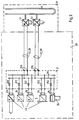
- FIG. 2 a supply system for a fieldbus is shown in FIG. 2, in which the PNK 12 and the fieldbus 22 are designed redundantly.
- Two PNK 12 are provided, each of which is supplied separately with auxiliary power 13 and each has a galvanically isolated connection to the control room bus 11.
- each PNK 12 has a separate, electrically isolated circuit to which a field bus 22 is connected.
- the connections of the redundant field buses 22 are connected in parallel to the busbars 211 via terminals 215 with increased security.
- the distributor 21 is supplemented by connections with increased security for non-intrinsically safe circuits.
- the connections in increased security 215 are without means directly connected to busbar 211 to limit current.
- stationary field devices in conventional types of protection are connected to connections 215 via non-intrinsically safe circuits 26 with increased safety of the distributor 21.
- These field devices can be analysis devices, for example. In this way, it is possible to connect both field devices with the protection type intrinsic safety 23 and 24 and field devices 27 in conventional ignition protection types to the same field bus 22.
- the busbars 211 of at least two distributors 21 are connected to one another with a non-intrinsically safe circuit 26 via connecting terminals with increased security 215.
- FIG. 4 shows a supply system for a field bus, in which a PNK 12 in the control room area 10 is connected to a control room bus 11 via electrically isolated connections.
- the PNK 12 is electrically isolated with auxiliary power 13.
- the PNK 12 has an electrically isolated current-limiting circuit to which the fieldbus 22 is connected.
- the PNK 12 preferably has a distributor 21 in the field region 20, which has a multiplicity of interlock diodes 214 and voltage limiter arrangements 213 connected in series, which are looped into the circuit of the field bus 22.
- the voltage limiter arrangements are realized with Zener diodes as voltage limiter diodes 213.
- the interlock diodes 214 are zener diodes with a smaller zener voltage than the voltage limiter diodes 213.
- the interlock diodes 214 are used to switch through the fieldbus current when the intrinsically safe field device input 25 is unoccupied, their zener voltage is greater than the operating voltage of the field devices plus a predetermined maximum voltage drop on the line 25.
- Each voltage limiter arrangement is a intrinsically safe circuit 25 assigned to which an intrinsically safe field device can be connected. These include stationary intrinsically safe field devices 23 and portable intrinsically safe field devices 24, for example hand held terminals.
- the fieldbus 22 is designed in the form of a two-wire line as a non-intrinsically safe circuit 26.
- FIG. 5 a supply system for a fieldbus is shown in FIG. 5, in which the fieldbus 22 and the PNK 12 are designed redundantly.
- Each PNK 12 has a separate feed for the auxiliary power 13 and a separate galvanically isolated connection to the control room bus 11.
- each PNK 12 means for current limitation or current regulation are implemented in a galvanically isolated circuit.
- the redundant field buses 22 are designed as non-intrinsically safe circuits 26 and connected in parallel in the distributor 21.
- stationary field devices 26 in conventional types of protection are connected to the distributor 21 via non-intrinsically safe circuits 26 via additional connecting terminals with increased security 26.
- the design differences between connections with increased safety and connections with intrinsic safety are expressed in the number of diodes assigned to the voltage limiter circuits. While an interlock diode 214 is sufficient to connect field devices in conventional types of protection, voltage limiter circuits for intrinsically safe circuits of the category “ib” redundant diode arrangements 213 are required.
Abstract
Description
Die Erfindung betrifft ein Speisesystem für einen Feldbus in explosionsgefährdeten verfahrenstechnischen Anlagen.The invention relates to a feed system for a fieldbus in explosion-hazardous process plants.
Feldbusse sind elektrische Einrichtungen zur Kommunikation zwischen im Feldbereich angeordneten Feldgeräten wie Sensoren, Aktoren und Meßumformer einerseits und im Wartenbereich angeordneten Steuerungs- und Regelungssystemen andererseits. Üblicherweise ist ein Feldbus als Zweidrahtleitung ausgeführt, die gleichzeitig zur Übertragung der Speiseleistung der angeschlossenen Feldgeräte dient. Die Kommunikation erfolgt analog über eine übliche 0/4...20 mA-Stromschleife oder digital, beispielsweise mittels FSK-Modulation oder mit einer kombiniert analog/digitalen Signalübertragung.Field buses are electrical devices for communication between field devices such as sensors, actuators and transmitters arranged in the field area on the one hand and control and regulation systems arranged in the waiting area on the other hand. A fieldbus is usually designed as a two-wire line, which also serves to transmit the power of the connected field devices. Communication takes place in an analog manner via a conventional 0/4 ... 20 mA current loop or digitally, for example by means of FSK modulation or with a combined analog / digital signal transmission.
Zur Verwendung in explosionsgefährdeten Anlagen sind an elektrische Einrichtungen besondere Anforderungen gestellt, um einen möglichen Explosionsunfall auszuschließen. Diese Anforderungen sind in sogenannten Zündschutzarten zusammengefaßt. Wegen der einfachen Handhabung bei Installation, Wartung und Reparatur wird für elektrische Einrichtungen an Stromkreisen im Feldbereich die Zündschutzart "Eigensicherheit", im folgenden Ex'i' genannt, bevorzugt.Electrical equipment has special requirements for use in potentially explosive systems in order to rule out a possible explosion accident. These requirements are summarized in so-called types of protection. Because of the easy handling during installation, maintenance and repair is for electrical devices on circuits in the field area prefer the type of protection "intrinsic safety", hereinafter referred to as Ex'i '.
Aus der Zeitschrift "Automatisierungstechnische Praxis 33 (1991) 9", Seiten 469-473, sind eine Reihe von Konzepten für Feldbussysteme für den Einsatz in explosionsgefährdeten Bereichen bekannt. Im Bild 1a ist die Struktur eines ersten Feldbussystems gezeigt, das ausgehend von einer sogenannten prozeßnahen Komponente, im folgenden PNK genannt, eine einzige Zweidrahtleitung zur Kommunikation und Speisung der Feldgeräte vorsieht, an die die einzelnen Feldgeräte angeschlossen sind. Das Feldbussystem ist ausschließlich in Ex'i' ausgeführt. Die Besonderheit dieser Zündschutzart liegt darin, daß es während des laufenden Betriebes gestattet ist, den in Ex'i' ausgeführten Stromkreis an beliebiger Stelle zu öffnen, kurzzuschließen und/oder zu erden. Die Leistung in einem Ex'i'-Stromkreis ist derart begrenzt, daß bei o.g. Handlungen sowohl zündende Funken als auch explosionsauslösende Erwärmungen von Bauelementen innerhalb des Ex'i'-Stromkreises sicher vermieden werden. Aus der Leistungsbegrenzung resultiert, daß, wie aus der Zeitschrift "Automatisierungstechnische Praxis 34 (1992) 11", Seiten 617-622, bekannt ist, weniger als 10 reale Feldgeräte an einen derart ausgeführten Feldbus in Bereichen der Explosionsgruppe IIC anschließbar sind. Die Begrenzung auf 10 Feldgeräte an einen Feldbus reicht aber nicht aus, da neben Analogsignalen für viele Meßumformergeräte oder Stellumformergeräte auch gleichzeitig Binärsignale für Kontakte, Näherungsinitiatoren und Magnetventile zu übertragen sind.A number of concepts for fieldbus systems for use in potentially explosive atmospheres are known from the magazine "automation engineering practice 33 (1991) 9", pages 469-473. Figure 1a shows the structure of a first fieldbus system, which, based on a so-called process-related component, hereinafter referred to as PNK, provides a single two-wire line for communication and supply of the field devices to which the individual field devices are connected. The fieldbus system is designed exclusively in Ex'i '. The peculiarity of this type of protection is that it is permitted to open, short-circuit and / or earth the circuit in Ex'i 'at any point during operation. The power in an Ex'i 'circuit is limited so that the above Actions both igniting sparks and explosion-causing heating of components within the Ex'i 'circuit can be safely avoided. As a result of the power limitation, as is known from the magazine "Automatisierungstechnik Praxis 34 (1992) 11", pages 617-622, fewer than 10 real field devices can be connected to a fieldbus designed in this way in areas of explosion group IIC. However, the limitation to 10 field devices on one fieldbus is not sufficient, since in addition to analog signals for many measuring transducer devices or positioning device devices, binary signals for contacts, proximity switches and solenoid valves must also be transmitted.
In Bild 1b ist die Struktur eines zweiten Feldbussystems gezeigt, bei dem die Kommunikation über eine Ex'i' ausgeführte Zweidrahtleitung realisiert ist und die Speisung der einzelnen Feldgeräte über jeweils separate Zuleitungen für die Hilfsenergie erfolgt. Das bedeutet zwar, daß einerseits eine Vielzahl von Feldgeräten an einen Feldbus anschließbar ist, aber andererseits für n Feldgeräte n+1 Leitungspaare aus dem Wartenbereich an die Feldgeräte zu, führen sind. Um die beschriebenen Vorzüge des in Ex'i' ausgeführten Feldbusses nutzen zu können, müssen zwangsläufig auch die Stromkreise der erforderlichen n Speiseleitungspaare in der Zündschutzart Ex'i' ausgeführt sein.Figure 1b shows the structure of a second fieldbus system, in which communication is implemented via an Ex'i 'two-wire line and the individual field devices are supplied via separate supply lines for the auxiliary power. That means that on the one hand a large number of field devices can be connected to a fieldbus, but on the other hand n + 1 line pairs from the control room area to n field devices are to be routed to the field devices. In order to be able to use the described advantages of the field bus implemented in Ex'i ', the circuits of the required n pairs of feed lines must inevitably be designed in Ex'i' type of protection.
Ein drittes Feldbussystem ist in Bild 1c gezeigt, das eine Kombination aus dem ersten und dem zweiten Feldbussystem darstellt, wobei eine Mehrzahl von Feldgeräten blockweise mit einer separat heranzuführenden und einzuspeisenden Hilfsenergie versorgt wird. Zur Kommunikation sind mehrere Blöcke an einen Feldbus geschaltet. Jedoch ist weiterhin eine Vielzahl von Leitungspaaren zwischen dem Wartenbereich und den Blöcken von Feldgeräten erforderlich.A third fieldbus system is shown in Figure 1c, which represents a combination of the first and the second fieldbus system, with a plurality of field devices being supplied block by block with an auxiliary energy that can be brought in and fed in separately. Several blocks are connected to a fieldbus for communication. However, a large number of line pairs are still required between the waiting area and the blocks of field devices.
Weiterhin ist in Bild 1d ein viertes Feldbussystem dargestellt, bei dem zwar eine Zweidrahtleitung zur Kommunikation und Speisung der Feldgeräte genügt, aber jedem Feldgerät eine Sicherheitsbarriere zugeordnet werden muß, um das Feldgerät an einem Ex'i'-Stromkreis betreiben zu können. Der Feldbus selbst ist als nichteigensicherer Stromkreis ausgeführt. Die im Feldbereich angeordneten Sicherheitsbarrieren sind zusätzlich druckfest gekapselt, Ex'd', also mit mechanisch aufwendig gefertigten, paßgenauen Ummantelungen versehen. Jede Barriere umfaßt jeweils Mittel zur Strombegrenzung, zur Spannungsbegrenzung, zum Potentialausgleich und zum thermischen Schutz für nachgeschaltete Bauelemente. Die Montage von Barrieren ist bisher nur im nicht-explosionsgefährdeten Bereich gestattet. Darüber hinaus ist jede Umrüstung, Aufrüstung oder sonstige Manipulation an Betriebsmitteln der Zündschutzarten Ex'e' und Ex'd' ausschließlich im abgeschalteten Zustand gestattet.Figure 1d also shows a fourth fieldbus system, in which a two-wire line is sufficient for communication and supplying the field devices, but a safety barrier must be assigned to each field device in order to operate the field device on an Ex'i 'circuit. The fieldbus itself is designed as a non-intrinsically safe circuit. The safety barriers arranged in the field area are additionally flameproof, 'Ex'd', i.e. provided with mechanically complex, precisely fitting sheathing. Each barrier includes means for current limitation, voltage limitation, equipotential bonding and thermal protection for downstream components. So far, the installation of barriers has only been permitted in the non-hazardous area. In addition, any retrofitting, upgrading or other manipulation of equipment with types of protection Ex'e 'and Ex'd' is only permitted when the device is switched off.
Die PNK ist bei angeschlossenen, eigensicheren Stromkreisen üblicherweise mit Mitteln zur Potentialtrennung sowie Mitteln zur Begrenzung von Strom und Spannung ausgestattet.When connected, intrinsically safe circuits, the PNK is usually equipped with means for potential isolation and means for limiting current and voltage.
Der Erfindung liegt daher die Aufgabe zugrunde, ein Speisesystem für einen Feldbus in explosionsgefährdeten Bereichen anzugeben, bei dem der Verkabelungsaufwand minimal ist, der auf die Verwendung weniger, konstruktiv einfacher Zündschutzarten beschränkt ist und der den Anschluß einer Vielzahl von Feldgeräten sowie deren freizügige Manipulation im Sinne der Schutzart Eigensicherheit im laufenden Betrieb gestattet.The invention is therefore based on the object of specifying a supply system for a fieldbus in potentially explosive areas, in which the cabling effort is minimal, which is limited to the use of fewer, structurally simple types of protection and which involves the connection of a large number of field devices and their free manipulation in the sense the protection class intrinsic safety allowed during operation.
Ausgehend von einem Feldbus, bei dem die Kommunikation und die Speisung der angeschlossenen Feldgeräte über dasselbe Adernpaar erfolgt, wird diese Aufgabe erfindungsgemäß dadurch gelöst, daß die Mittel zur Strom- und Spannungsbegrenzung räumlich getrennt angeordnet und über einen nichteigensicheren Stromkreis verbunden sind.Starting from a fieldbus, in which the communication and the supply of the connected field devices takes place via the same pair of wires, this object is achieved according to the invention in that the means for current and voltage limitation are arranged spatially separated and connected via a non-intrinsically safe circuit.
Im Wartenbereich ist eine PNK vorgesehen, die mit Mitteln zur Spannungs- oder Strombegrenzung und zur galvanisch getrennten Einspeisung der Hilfsenergie für die Feldgeräte ausgestattet ist. Im Feldbereich ist ein Verteiler mit einem Eingangsklemmenpaar und einer Vielzahl von Ausgangsklemmenpaaren vorgesehen. Die Ausgangsklemmenpaare sind eingeteilt in eigensichere und optionale nichteigensichere Anschlußpaare. Den eigensicheren Anschlußpaaren sind jeweils Mittel zur Strom- oder Spannungsbegrenzung zugeordnet.A PNK is provided in the waiting area, which is equipped with means for voltage or current limitation and for the galvanically isolated supply of auxiliary energy for the field devices. A distributor with one pair of input terminals and a large number of pairs of output terminals is provided in the field area. The output terminal pairs are divided into intrinsically safe and optional non-intrinsically safe connection pairs. Means for current or voltage limitation are assigned to the intrinsically safe connection pairs.
Optional sind der Feldbus und die PNK redundant ausgeführt. In weiterer Ausgestaltung der Erfindung sind mehrere Verteiler kaskadiert an einen Feldbus anschaltbar.The fieldbus and the PNK are optionally redundant. In a further embodiment of the invention, a plurality of distributors can be cascaded connected to a fieldbus.
Vorteilhafterweise genügt eine Zweidrahtleitung zwischen der PNK im Wartenbereich und dem abgesetzten Verteiler im Feldbereich zur Kommunikation einer im Wartenbereich vorgesehenen Steuerung mit allen einem Feldbus zugeordneten Feldgeräten und zur Speisung aller über den Verteiler an den Feldbus angeschlossenen Feldgeräte. Der Feldbus ist als nichteigensicherer Stromkreis und der Verteiler in der Schutzart Ex'e' ausgeführt, so daß neben der feldgeräteseitig geforderten Schutzart Ex'i' auf mechanisch aufwendig zu realisierende Schutzarten verzichtet werden kann.Advantageously, a two-wire line between the PNK in the waiting area and the remote distributor in the field area is sufficient to communicate a control provided in the waiting area with all field devices assigned to a field bus and to supply all field devices connected to the field bus via the distributor. The fieldbus is designed as a non-intrinsically safe circuit and the distributor with protection class Ex'e ', so that in addition to the protection class Ex'i' required on the field device, protection classes that are mechanically complex can be dispensed with.
Die maximale Anzahl anschließbarer Feldgeräte ist unabhängig von der Leistungsbegrenzung in eigensicheren Stromkreisen und ist nur noch durch das kaskadierbare Leistungsvermögen der PNK bestimmt. Bei Spannungsbegrenzung in der PNK kann der Strom im Feldbus hohe Werte annehmen, während bei Strombegrenzung in der PNK di Spannung hohe Werte annehmen kann, so daß sehr hohe Leistungen ins Feld übertragen werden können.The maximum number of connectable field devices is independent of the power limitation in intrinsically safe circuits and is only determined by the cascadable capacity of the PNK. With voltage limitation in the PNK, the current in the fieldbus can assume high values, while with current limitation in the PNK, the voltage can assume high values, so that very high powers can be transmitted into the field.
Von besonderem Vorteil ist, daß mit dem erfindungsgemäßen Speisesystem Feldgeräte, die der Schutzart "Eigensicherheit" genügen, zusammen mit Feldgeräten in konventionellen Zündschutzarten, wie z. B. "erhöhte Sicherheit", Überdruckkapselung, Sandkapselung, druckfeste Kapselung und Vergußkapselung, an denselben Feldbus anschließbar sind. Dadurch können kurze Übertragungswege zwischen beiden Feldgerätearten realisiert werden.It is particularly advantageous that with the feed system according to the invention, field devices which meet the "intrinsically safe" protection type, together with field devices in conventional types of protection, such as, for. B. "increased safety", pressurized encapsulation, sand encapsulation, pressure-resistant encapsulation and encapsulation encapsulation, can be connected to the same fieldbus. This enables short transmission paths to be implemented between the two types of field devices.
Die Erfindung wird nachstehend anhand von Ausführungsbeispielen näher erläutert. Es zeigen:
- Fig. 1
- Darstellung eines Speisesystems für einen Feldbus mit Spannungsbegrenzung in der Warte und Strombegrenzung im Feld.
- Fig. 2
- Darstellung wie Fig. 1, jedoch mit redundant ausgeführtem Feldbus und PNK,
- Fig. 3
- Darstellung wie Fig. 1 mit zusätzlichen Feldgeräten in konventionellen Zündschutzarten.
- Fig. 4
- Darstellung eines Speisesystems für einen Feldbus mit Strombegrenzung in der Warte und Spannungsbegrenzung
- Fig. 5
- Darstellung wie Fig. 4 mit redundant ausgeführtem Feldbus und PNK,
- Fig. 6
- Darstellung wie Fig. 4 mit zusätzlichen Feldgeräten in konventionellen Zündschutzarten.
- Fig. 1
- Representation of a supply system for a fieldbus with voltage limitation in the control room and current limitation in The Field.
- Fig. 2
- Representation as in FIG. 1, but with a redundant fieldbus and PNK,
- Fig. 3
- Representation as Fig. 1 with additional field devices in conventional types of protection.
- Fig. 4
- Representation of a supply system for a fieldbus with current limitation in the control room and voltage limitation
- Fig. 5
- Representation like FIG. 4 with redundant fieldbus and PNK,
- Fig. 6
- Representation as Fig. 4 with additional field devices in conventional types of protection.
Gemäß Fig. 1 ist im Wartenbereich 10 eine PNK 12 vorgesehen, die jeweils galvanisch voneinander getrennte Stromkreise für die Einspeisung der Hilfsenergie 13 für den Wartenbus 11 und für den Feldbus 22 aufweist. An den Wartenbus 11 sind Einrichtungen zur Prozeßsteuerung, -regelung und -visualisierung anschließbar. Der Feldbus 22 ist als nichteigensicherer Stromkreis 26 ausgeführt und im Feldbereich 20 (Zone 1) an einen Verteiler 21 über Klemmen in erhöhter Sicherheit 215, angeschlossen. Diese Anschlußklemmen sind gegen Selbstlockern und Selbstlösen gesichert. Der Verteiler 21 ist mit Sammelleitern 211 ausgestattet, die an den Feldbus 22 angeschlossen sind. Der Verteiler 21 weist darüber hinaus eine Mehrzahl von Anschlüssen für eigensichere Stromkreise 25 auf, denen jeweils Mittel zur Strombegrenzung (ohm'sch oder elektronisch) zugeordnet sind. Die Mittel zur Strombegrenzung sind in der Fig. 1 als ohmsche Widerstände 212 ausgeführt und an die Sammelleiter 211 angeschlossen. Im Feldbereich sind darüber hinaus stationäre eigensichere Feldgeräte 23 dargestellt, die über eigensichere Stromkreise 25 an den Verteiler 21 angeschlossen sind. Darüber hinaus ist ein portables eigensicheres Feldgerät 24, ein sogenanntes hand held terminal, dargestellt, das ebenfalls über einen eigensicheren Stromkreis 25 mit Hilfe von Steckkontakten an den Verteiler 21 anschließbar ist.According to FIG. 1, a
Den Erfordernissen der Zündschutzart Eigensicherheit wird durch galvanische Trennung und Spannungsbegrenzung in dem PNK 12 sowie Strombegrenzung im Verteiler 21 realisiert. Dabei genügt für eine Vielzahl von Feldgeräten eine einzige galvanische Trennung im Wartenbereich und die einfache Ausführung der Spannungsbegrenzung in der PNK. Vorzugsweise ist der Spannungsbegrenzung eine Spannungsregelung vorgeschaltet.The requirements of the type of protection intrinsic safety are realized by galvanic isolation and voltage limitation in the
Unter Verwendung gleicher Mittel und gleicher Bezugszeichen ist in Fig. 2 ein Speisesystem für einen Feldbus dargestellt, bei dem die PNK 12 und der Feldbus 22 redundant ausgeführt sind. Es sind zwei PNK 12 vorgesehen, die jeweils separat mit Hilfsenergie 13 versorgt sind und jeweils einen galvanisch getrennten Anschluß an den Wartenbus 11 aufweisen. Darüber hinaus weist jede PNK 12 einen separaten, galvanisch getrennten Stromkreis auf, an den jeweils ein Feldbus 22 angeschlossen ist. Im Verteiler 21 sind die Anschlüsse der redundanten Feldbusse 22 parallel an die Sammelleiter 211 über Anschlußklemmen in erhöhter Sicherheit 215 angeschlossen.Using the same means and the same reference numerals, a supply system for a fieldbus is shown in FIG. 2, in which the
In weiterer Ausgestaltung der Erfindung ist in Fig. 3 unter Verwendung gleicher Mittel und Bezugszeichen der Verteiler 21 um Anschlüsse in erhöhter Sicherheit für nichteigensichere Stromkreise ergänzt. Die Anschlüsse in erhöhter Sicherheit 215 sind unter Verzicht auf Mittel zur Strombegrenzung direkt an die Sammelleiter 211 angeschlossen. Im Feldbereich sind stationäre Feldgeräte in konventionellen Zündschutzarten über nichteigensichere Stromkreise 26 an Anschlüsse 215 in erhöhter Sicherheit des Verteilers 21 angeschlossen. Bei diesen Feldgeräten kann es sich z.B. um Analysegeräte handeln. Auf diese Weise ist es möglich, an denselben Feldbus 22 sowohl Feldgeräte der Schutzart Eigensicherheit 23 und 24 als auch Feldgeräte 27 in konventionellen Zündschutzarten anzuschließen.In a further embodiment of the invention, in FIG. 3, using the same means and reference numerals, the
Weiterhin ist vorgesehen, den Verteiler 21 zu kaskadieren. Dabei sind die Sammelleiter 211 mindestens zweier Verteiler 21 über Anschlußklemmen in erhöhter Sicherheit 215 mit einem nichteigensicheren Stromkreis 26 miteinander verbunden.Provision is also made to cascade the
In Fig. 4 ist ein Speisesystem für einen Feldbus dargestellt, bei dem im Wartenbereich 10 eine PNK 12 über galvanisch getrennte Anschlüsse mit einem Wartenbus 11 verbunden ist. Die PNK 12 ist galvanisch getrennt mit Hilfsenergie 13 versorgt. Darüber hinaus weist die PNK 12 einen galvanisch getrennten Stromkreis mit Strombegrenzung auf, an den der Feldbus 22 angeschlossen ist. Vorzugsweise weist die PNK 12 im Feldbereich 20 ist ein Verteiler 21 vorgesehen, der eine Vielzahl von in Reihe geschalteten Interlockdioden 214 und Spannungsbegrenzeranordnungen 213 aufweist, die in den Stromkreis des Feldbusses 22 eingeschleift sind. Die Spannungsbegrenzeranordnungen sind mit Zenerdioden als Spannungsbegrenzerdioden 213 realisiert. Die Interlockdioden 214 sind Zenerdioden mit einer kleineren Zenerspannung als die Spannungsbegrenzerdioden 213. Die Interlockdioden 214 dienen dazu, bei unbelegten eigensicheren Feldgeräteeingang 25 den Feldbusstrom durchzuschalten, ihre Zenerspannung ist größer als die Betriebsspannung der Feldgeräte zuzüglich einem vorgegebenen maximalen Spannungsabfall auf der Leitung 25. Jeder Spannungsbegrenzeranordnung ist ein eigensicherer Stromkreis 25 zugeordnet, an dem ein eigensicheres Feldgerät anschließbar ist. Dazu gehören stationäre eigensichere Feldgeräte 23 sowie portable eigensichere Feldgeräte 24, z.B. hand held terminals. Der Feldbus 22 ist in Form einer Zweidrahtleitung als nichteigensicherer Stromkreis 26 ausgeführt.4 shows a supply system for a field bus, in which a
Unter Verwendung gleicher Mittel und Bezugszeichen ist in Fig. 5 ein Speisesystem für einen Feldbus dargestellt, bei dem der Feldbus 22 und die PNK 12 redundant ausgeführt sind. Jede PNK 12 weist eine separate Einspeisung für die Hilfsenergie 13 auf sowie einen separaten galvanisch getrennten Anschluß an den Wartenbus 11. Darüber hinaus sind in jeder PNK 12 in gleicher Weise Mittel zur Strombegrenzung bzw. Stromregelung in einem galvanisch getrennten Stromkreis realisiert. Die redundanten Feldbusse 22 sind als nichteigensichere Stromkreise 26 ausgeführt und im Verteiler 21 parallelgeschaltet.Using the same means and reference numerals, a supply system for a fieldbus is shown in FIG. 5, in which the fieldbus 22 and the
In weiterer Ausgestaltung der Erfindung ist gemäß Fig. 6 vorgesehen, stationäre Feldgeräte 26 in konventionellen Zündschutzarten über nichteigensichere Stromkreise 26 über weitere Anschlußklemmen in erhöhter Sicherheit 26 an den Verteiler 21 anzuschließen. Die bauartgemäßen Unterschiede zwischen Anschlüssen in erhöhter Sicherheit und Anschlüssen in Eigensicherheit äußern sich in der Anzahl der den Spannungsbegrenzerschaltungen zugeordneten Dioden. Während zum Anschluß von Feldgeräten in konventionellen Zündschutzarten eine Interlockdiode 214 genügt, sind Spannungsbegrenzerschaltungen für eigensichere Stromkreise der Kategorie "ib" redundante Diodenanordnungen 213 erforderlich.In a further embodiment of the invention, according to FIG. 6,
- 1010th
- Wartenbereich (nicht explosionsgefährdet)Waiting area (not explosive)
- 1111
- WartenbusWaiting bus
- 12,12,
- PNK, prozeßnahe KomponentenPNK, process-related components
- 1313
- HilfsenergieAuxiliary energy
- 2020th
- Feldbereich (Zone 1)Field area (zone 1)
- 2121
- VerteilerDistributor
- 211211
- SammelleiterBusbar
- 212212
- StrombegrenzungswiderstandCurrent limiting resistor
- 213213
- SpannungsbegrenzerdiodenVoltage limiter diodes
- 214214
- InterlockdiodenInterlock diodes
- 215,215,
- Anschlußklemmen mit erhöhter SicherheitTerminal blocks with increased security
- 2222
- FeldbusFieldbus
- 2323
- stationäres eigensicheres Feldgerätstationary intrinsically safe field device
- 2424th
- portables eigensicheres Feldgerätportable intrinsically safe field device
- 2525th
- eigensicherer Stromkreisintrinsically safe circuit
- 26,26,
- nichteigensicherer Stromkreisnon-intrinsically safe circuit
- 2727
- stationäres Feldgerät in konventionellen Zündschutzartenstationary field device in conventional types of protection
Claims (4)
dadurch gekennzeichnet,
daß die Mittel zur Strombegrenzung räumlich von den Mitteln zur Spannungsbegrenzung getrennt angeordnet sind und über einen nichteigensicheren Stromkreis miteinander verbunden sind.Power supply system for a fieldbus in potentially explosive systems, in which the communication and the power supply of the connected field devices take place via the same pair of wires and the means for voltage and current limitation are assigned,
characterized,
that the means for current limitation are arranged spatially separated from the means for voltage limitation and are connected to one another via a non-intrinsically safe circuit.
dadurch gekennzeichnet,
daß die prozeßnahe Komponente (12) mit Mitteln zur Spannungs- oder Strombegrenzung ausgestattet ist und daS im Feldbereich (20) ein Verteiler (21) vorgesehen ist, an dem eigensichere und nichteigensichere Feldgeräte (23, 24, 27) anschließbar sind und der bei Spannungsbegrenzung in der prozeßnahe Komponenten für jedes eigensichere Feldgerät (23, 24) Mittel zur Strombegrenzung oder bei Strombegrenzung in der prozeßnahe Komponenten für jedes Feldgerät (23, 24, 27) Mittel zur Spannungsbegrenzung aufweist.Feeding system according to claim 1, with at least one process-related component (12) arranged in the waiting area (10),
characterized,
that the process-related component (12) is equipped with means for voltage or current limitation and that a distributor (21) is provided in the field area (20), to which intrinsically safe and non-intrinsically safe field devices (23, 24, 27) can be connected and which for voltage limitation in the process-related components for each intrinsically safe field device (23, 24) means for current limitation or in the process-related components for each field device (23, 24, 27) means for voltage limitation.
dadurch gekennzeichnet,
daß der Feldbus (22) und die prozeßnahe Komponente (12) redundant ausgeführt sind.Feeding system according to claim 2,
characterized,
that the fieldbus (22) and the process-related component (12) are designed redundantly.
dadurch gekennzeichnet,
daß der Verteiler (21) kaskadierbar ist.Feeding system according to one of claims 2 and 3,
characterized,
that the distributor (21) can be cascaded.
Applications Claiming Priority (2)
| Application Number | Priority Date | Filing Date | Title |
|---|---|---|---|
| DE4403961 | 1994-02-04 | ||
| DE4403961A DE4403961C2 (en) | 1994-02-04 | 1994-02-04 | Feeding system for an intrinsically safe fieldbus |
Publications (3)
| Publication Number | Publication Date |
|---|---|
| EP0666631A2 true EP0666631A2 (en) | 1995-08-09 |
| EP0666631A3 EP0666631A3 (en) | 1997-03-26 |
| EP0666631B1 EP0666631B1 (en) | 1999-12-15 |
Family
ID=6509792
Family Applications (1)
| Application Number | Title | Priority Date | Filing Date |
|---|---|---|---|
| EP95250024A Expired - Lifetime EP0666631B1 (en) | 1994-02-04 | 1995-01-31 | Field bus power supply system |
Country Status (2)
| Country | Link |
|---|---|
| EP (1) | EP0666631B1 (en) |
| DE (2) | DE4403961C2 (en) |
Cited By (27)
| Publication number | Priority date | Publication date | Assignee | Title |
|---|---|---|---|---|
| WO1997049017A1 (en) * | 1996-06-17 | 1997-12-24 | Endress + Hauser Conducta Gesellschaft Für Mess- Und Regeltechnik Mbh & Co. | Circuit enabling external devices to communicate with central/decentralised data processing system by means of a bus |
| WO1998005111A1 (en) * | 1996-07-29 | 1998-02-05 | Siemens Aktiengesellschaft | Switching installation |
| DE19719730C1 (en) * | 1997-05-09 | 1998-10-22 | Bartec Mestechnik Und Sensorik | Plug connector for use in explosive area |
| EP0923163A2 (en) * | 1997-12-13 | 1999-06-16 | Weidmüller Interface GmbH & Co. | Bus system arrangement, in particular for measuring apparatuses |
| WO1999045621A1 (en) * | 1998-03-06 | 1999-09-10 | Abb Patent Gmbh | Field bus system with a field bus distributor |
| EP0997825A2 (en) * | 1998-10-30 | 2000-05-03 | Siemens Aktiengesellschaft | Power supply for a computer bus |
| EP0998002A2 (en) * | 1998-10-28 | 2000-05-03 | Siemens Aktiengesellschaft | DC supply unit |
| WO2001082442A1 (en) * | 2000-04-25 | 2001-11-01 | Hawke Cable Glands Limited | Digital instrumentation |
| EP1290513A2 (en) | 2000-05-12 | 2003-03-12 | Rosemount Inc. | Two-wire field-mounted process device |
| WO2003034564A1 (en) * | 2001-10-16 | 2003-04-24 | Pepperl + Fuchs Gmbh | Intrinsically secure device for supplying redundant current-voltage |
| DE10220708A1 (en) * | 2002-05-10 | 2003-11-27 | Abb Patent Gmbh | Supply system for a self protective field bus in explosion risk areas, has controlled ratio of inductance to insulation resistance |
| US6897639B2 (en) | 2001-09-19 | 2005-05-24 | Vega Grieshaber Kg | Circuit arrangement for the power supply of a two-wire sensor |
| US7016741B2 (en) | 2003-10-14 | 2006-03-21 | Rosemount Inc. | Process control loop signal converter |
| US7117122B2 (en) | 2001-12-06 | 2006-10-03 | Fisher-Rosemount Systems, Inc. | Field maintenance tool |
| EP1489476A3 (en) * | 2001-12-06 | 2006-12-06 | Fisher-Rosemount Systems, Inc. | Intrinsically safe field maintenance tool |
| US7228186B2 (en) | 2000-05-12 | 2007-06-05 | Rosemount Inc. | Field-mounted process device with programmable digital/analog interface |
| WO2008074609A2 (en) * | 2006-12-19 | 2008-06-26 | Endress+Hauser Wetzer Gmbh+Co. Kg | Two-wire field device for process automation technology for connecting at least one sensor element |
| US7835295B2 (en) | 2005-07-19 | 2010-11-16 | Rosemount Inc. | Interface module with power over Ethernet function |
| US7844365B2 (en) | 2000-05-12 | 2010-11-30 | Rosemount Inc. | Field-mounted process device |
| WO2011092651A1 (en) * | 2010-02-01 | 2011-08-04 | Bucyrus Europe Gmbh | Intrinsically safe connection unit with a network interface, intrinsically safe appliance and network interface for it |
| WO2011144399A1 (en) | 2010-05-21 | 2011-11-24 | Endress+Hauser Flowtec Ag | Device for providing an intrinsically safe supply voltage and for transmitting communication signals |
| US8311778B2 (en) | 2009-09-22 | 2012-11-13 | Rosemount Inc. | Industrial process control transmitter with multiple sensors |
| DE102012111018A1 (en) * | 2012-11-15 | 2014-05-15 | Systemplan GmbH | Multichannel measurement data acquisition device for microprocessor-controlled data recording, comprises input channels operatively connected to data storage unit, and power supply unit for providing input channels with supply voltages |
| CN105373176A (en) * | 2014-08-06 | 2016-03-02 | Abb技术股份公司 | Method and device for the intrinsically safe redundant current supply of field devices |
| US9634858B2 (en) | 2005-07-20 | 2017-04-25 | Rosemount Inc. | Field device with power over Ethernet |
| WO2017178470A3 (en) * | 2016-04-13 | 2017-12-14 | R. Stahl Schaltgeräte GmbH | Module for providing an intrinsically safe electrical output power and explosion-proof luminaire |
| US11159203B2 (en) | 2019-09-13 | 2021-10-26 | Micro Motion, Inc. | Process control loop bridge |
Families Citing this family (7)
| Publication number | Priority date | Publication date | Assignee | Title |
|---|---|---|---|---|
| DE19803543B4 (en) * | 1998-01-30 | 2004-01-29 | Bartec Componenten Und Systeme Gmbh | Electrical device for energy and data transmission in potentially explosive areas |
| GB0016524D0 (en) * | 2000-07-06 | 2000-08-23 | Mtl Instr Group The Plc | Protection of incendive circuits |
| DE10052846C2 (en) * | 2000-10-25 | 2003-10-16 | Abb Patent Gmbh | Arrangement for branching electrical circuits in the hazardous area |
| FR2819656B1 (en) * | 2001-01-12 | 2004-05-28 | Schneider Electric Ind Sa | VOLTAGE LIMITER FOR INTERFACE CIRCUIT OF A COMMUNICATION BUS |
| DE10253865B4 (en) * | 2002-11-15 | 2007-05-24 | Siemens Ag | Method for the determination of electrical variables characterizing a polyphase electrical equipment |
| DE10335203A1 (en) * | 2003-07-30 | 2005-03-10 | Flowtec Ag | Service interface for connection to field devices of process automation |
| DE102022105194A1 (en) | 2022-03-04 | 2023-09-07 | Endress+Hauser SE+Co. KG | Adapter for a field device in automation technology |
Citations (2)
| Publication number | Priority date | Publication date | Assignee | Title |
|---|---|---|---|---|
| DE2458590A1 (en) * | 1974-01-25 | 1975-07-31 | Mess & Regelungst Veb K | Fire and explosion proof instr. transformer with remote power supply - has supply outside danger zone and limiters independently protecting both units |
| GB2238191A (en) * | 1989-10-19 | 1991-05-22 | Drexelbrook Controls | Intrinsically safe system |
-
1994
- 1994-02-04 DE DE4403961A patent/DE4403961C2/en not_active Expired - Fee Related
-
1995
- 1995-01-31 DE DE59507404T patent/DE59507404D1/en not_active Expired - Fee Related
- 1995-01-31 EP EP95250024A patent/EP0666631B1/en not_active Expired - Lifetime
Patent Citations (2)
| Publication number | Priority date | Publication date | Assignee | Title |
|---|---|---|---|---|
| DE2458590A1 (en) * | 1974-01-25 | 1975-07-31 | Mess & Regelungst Veb K | Fire and explosion proof instr. transformer with remote power supply - has supply outside danger zone and limiters independently protecting both units |
| GB2238191A (en) * | 1989-10-19 | 1991-05-22 | Drexelbrook Controls | Intrinsically safe system |
Non-Patent Citations (1)
| Title |
|---|
| ADVANCES IN INSTRUMENTATION AND CONTROL, Bd. 46, Nr. PART 02, 1.Januar 1991, Seiten 1799-1813, XP000347609 LINDNER K P ET AL: "FIELDBUS IN HAZARDOUS AREAS" * |
Cited By (41)
| Publication number | Priority date | Publication date | Assignee | Title |
|---|---|---|---|---|
| WO1997049017A1 (en) * | 1996-06-17 | 1997-12-24 | Endress + Hauser Conducta Gesellschaft Für Mess- Und Regeltechnik Mbh & Co. | Circuit enabling external devices to communicate with central/decentralised data processing system by means of a bus |
| WO1998005111A1 (en) * | 1996-07-29 | 1998-02-05 | Siemens Aktiengesellschaft | Switching installation |
| US6137776A (en) * | 1996-07-29 | 2000-10-24 | Siemens Aktiengesellschaft | Switching station |
| DE19719730C1 (en) * | 1997-05-09 | 1998-10-22 | Bartec Mestechnik Und Sensorik | Plug connector for use in explosive area |
| WO1998052172A2 (en) * | 1997-05-09 | 1998-11-19 | Bartec Componenten Und Systeme Gmbh | Plug-and-socket connection for power and data transmission |
| WO1998052172A3 (en) * | 1997-05-09 | 1999-05-27 | Bartec Componenten & Syst Gmbh | Plug-and-socket connection for power and data transmission |
| US6476520B1 (en) | 1997-05-09 | 2002-11-05 | Bartec Componenten Und Systeme Gmbh | Plug connection |
| EP0923163A2 (en) * | 1997-12-13 | 1999-06-16 | Weidmüller Interface GmbH & Co. | Bus system arrangement, in particular for measuring apparatuses |
| EP0923163B1 (en) * | 1997-12-13 | 2008-12-10 | Weidmüller Interface GmbH & Co. | Bus system arrangement, in particular for measuring apparatuses |
| WO1999045621A1 (en) * | 1998-03-06 | 1999-09-10 | Abb Patent Gmbh | Field bus system with a field bus distributor |
| EP0998002A3 (en) * | 1998-10-28 | 2001-04-18 | Siemens Aktiengesellschaft | DC supply unit |
| EP0998002A2 (en) * | 1998-10-28 | 2000-05-03 | Siemens Aktiengesellschaft | DC supply unit |
| EP0997825A3 (en) * | 1998-10-30 | 2003-11-19 | Siemens Aktiengesellschaft | Power supply for a computer bus |
| EP0997825A2 (en) * | 1998-10-30 | 2000-05-03 | Siemens Aktiengesellschaft | Power supply for a computer bus |
| WO2001082442A1 (en) * | 2000-04-25 | 2001-11-01 | Hawke Cable Glands Limited | Digital instrumentation |
| EP1290513A2 (en) | 2000-05-12 | 2003-03-12 | Rosemount Inc. | Two-wire field-mounted process device |
| US7844365B2 (en) | 2000-05-12 | 2010-11-30 | Rosemount Inc. | Field-mounted process device |
| US6961624B2 (en) | 2000-05-12 | 2005-11-01 | Rosemount Inc. | Two-wire field-mounted process device |
| US7228186B2 (en) | 2000-05-12 | 2007-06-05 | Rosemount Inc. | Field-mounted process device with programmable digital/analog interface |
| US6897639B2 (en) | 2001-09-19 | 2005-05-24 | Vega Grieshaber Kg | Circuit arrangement for the power supply of a two-wire sensor |
| US7091631B2 (en) | 2001-10-16 | 2006-08-15 | Pepperl & Fuchs Gmbh | Intrinsically secure device for supplying redundant current-voltage |
| WO2003034564A1 (en) * | 2001-10-16 | 2003-04-24 | Pepperl + Fuchs Gmbh | Intrinsically secure device for supplying redundant current-voltage |
| EP1489476A3 (en) * | 2001-12-06 | 2006-12-06 | Fisher-Rosemount Systems, Inc. | Intrinsically safe field maintenance tool |
| US7117122B2 (en) | 2001-12-06 | 2006-10-03 | Fisher-Rosemount Systems, Inc. | Field maintenance tool |
| DE10220708B4 (en) * | 2002-05-10 | 2008-08-07 | Abb Ag | Feed system for an intrinsically safe fieldbus |
| DE10220708A1 (en) * | 2002-05-10 | 2003-11-27 | Abb Patent Gmbh | Supply system for a self protective field bus in explosion risk areas, has controlled ratio of inductance to insulation resistance |
| US7016741B2 (en) | 2003-10-14 | 2006-03-21 | Rosemount Inc. | Process control loop signal converter |
| US7835295B2 (en) | 2005-07-19 | 2010-11-16 | Rosemount Inc. | Interface module with power over Ethernet function |
| US9634858B2 (en) | 2005-07-20 | 2017-04-25 | Rosemount Inc. | Field device with power over Ethernet |
| WO2008074609A2 (en) * | 2006-12-19 | 2008-06-26 | Endress+Hauser Wetzer Gmbh+Co. Kg | Two-wire field device for process automation technology for connecting at least one sensor element |
| WO2008074609A3 (en) * | 2006-12-19 | 2008-09-18 | Endress & Hauser Wetzer Gmbh | Two-wire field device for process automation technology for connecting at least one sensor element |
| US8311778B2 (en) | 2009-09-22 | 2012-11-13 | Rosemount Inc. | Industrial process control transmitter with multiple sensors |
| US9166801B2 (en) | 2010-02-01 | 2015-10-20 | Caterpillar Global Mining Europe Gmbh | Intrinsically safe connection unit with a network interface, intrinsically safe appliance and network interface for it |
| WO2011092651A1 (en) * | 2010-02-01 | 2011-08-04 | Bucyrus Europe Gmbh | Intrinsically safe connection unit with a network interface, intrinsically safe appliance and network interface for it |
| DE102010029234A1 (en) | 2010-05-21 | 2011-11-24 | Endress + Hauser Flowtec Ag | Device for providing an intrinsically safe supply voltage and for transmitting communication signals |
| EP2665195A1 (en) | 2010-05-21 | 2013-11-20 | Endress + Hauser Flowtec AG | Device for providing an intrinsically safe supply voltage and for transmitting communication signals |
| WO2011144399A1 (en) | 2010-05-21 | 2011-11-24 | Endress+Hauser Flowtec Ag | Device for providing an intrinsically safe supply voltage and for transmitting communication signals |
| DE102012111018A1 (en) * | 2012-11-15 | 2014-05-15 | Systemplan GmbH | Multichannel measurement data acquisition device for microprocessor-controlled data recording, comprises input channels operatively connected to data storage unit, and power supply unit for providing input channels with supply voltages |
| CN105373176A (en) * | 2014-08-06 | 2016-03-02 | Abb技术股份公司 | Method and device for the intrinsically safe redundant current supply of field devices |
| WO2017178470A3 (en) * | 2016-04-13 | 2017-12-14 | R. Stahl Schaltgeräte GmbH | Module for providing an intrinsically safe electrical output power and explosion-proof luminaire |
| US11159203B2 (en) | 2019-09-13 | 2021-10-26 | Micro Motion, Inc. | Process control loop bridge |
Also Published As
| Publication number | Publication date |
|---|---|
| EP0666631A3 (en) | 1997-03-26 |
| DE4403961A1 (en) | 1995-08-10 |
| DE4403961C2 (en) | 1997-07-03 |
| EP0666631B1 (en) | 1999-12-15 |
| DE59507404D1 (en) | 2000-01-20 |
Similar Documents
| Publication | Publication Date | Title |
|---|---|---|
| EP0666631B1 (en) | Field bus power supply system | |
| DE4440102C1 (en) | Modular control system with integrated fieldbus connection | |
| EP1965482B1 (en) | ASI network for areas subject to explosive risk | |
| EP1012960B1 (en) | Three-phase motor | |
| EP1060552B1 (en) | Field bus system with a field bus distributor | |
| EP0929948B1 (en) | Wireless energy and data transfer for a modular peripheral system | |
| DE10135980C1 (en) | Arrangement for connection of decentralized local field devices to remote central station, has input/output units with system- and field-side communications interfaces in same plug plane | |
| EP0209765B1 (en) | Electrical distribution installation | |
| EP1436874B1 (en) | Intrinsically secure device for supplying redundant current-voltage | |
| EP1364459B1 (en) | Safety switch device | |
| DE2316039C2 (en) | Arrangement in a control system for separating a control area having a power source from a work area | |
| EP1169762B1 (en) | Bus system with a data bus line and a power bus line | |
| DE19910409A1 (en) | Fieldbus arrangement with a fieldbus distributor | |
| EP0103151B1 (en) | Method of operating an electric-energy distribution installation | |
| DE3122109C2 (en) | ||
| EP0807999A1 (en) | Power distribution system | |
| DE102008018256A1 (en) | Control module with connection devices for connection to connection terminals of a load feeder and load feeder | |
| DE10052846C2 (en) | Arrangement for branching electrical circuits in the hazardous area | |
| EP0663114B1 (en) | Digital protective relay arrangement | |
| DE102019215606B3 (en) | Supply module | |
| EP3544055B1 (en) | Electrical switching apparatus and method for producing an electrical switching apparatus | |
| EP0888707B1 (en) | Module with a circuit arrangement | |
| EP1251596B2 (en) | Multipolar connector for control and automatic systems | |
| DE102004059106B4 (en) | Device for supplying power to field devices (I) | |
| DE2644416B2 (en) | Intrinsically safe coupling link |
Legal Events
| Date | Code | Title | Description |
|---|---|---|---|
| PUAI | Public reference made under article 153(3) epc to a published international application that has entered the european phase |
Free format text: ORIGINAL CODE: 0009012 |
|
| AK | Designated contracting states |
Kind code of ref document: A2 Designated state(s): DE FR GB IT NL |
|
| PUAL | Search report despatched |
Free format text: ORIGINAL CODE: 0009013 |
|
| AK | Designated contracting states |
Kind code of ref document: A3 Designated state(s): DE FR GB IT NL |
|
| RAP1 | Party data changed (applicant data changed or rights of an application transferred) |
Owner name: HARTMANN & BRAUN AKTIENGESELLSCHAFT |
|
| 17P | Request for examination filed |
Effective date: 19970911 |
|
| RAP1 | Party data changed (applicant data changed or rights of an application transferred) |
Owner name: HARTMANN & BRAUN GMBH & CO. KG |
|
| 17Q | First examination report despatched |
Effective date: 19980618 |
|
| GRAG | Despatch of communication of intention to grant |
Free format text: ORIGINAL CODE: EPIDOS AGRA |
|
| GRAG | Despatch of communication of intention to grant |
Free format text: ORIGINAL CODE: EPIDOS AGRA |
|
| GRAH | Despatch of communication of intention to grant a patent |
Free format text: ORIGINAL CODE: EPIDOS IGRA |
|
| GRAH | Despatch of communication of intention to grant a patent |
Free format text: ORIGINAL CODE: EPIDOS IGRA |
|
| RAP1 | Party data changed (applicant data changed or rights of an application transferred) |
Owner name: HARTMANN & BRAUN GMBH & CO. KG |
|
| GRAH | Despatch of communication of intention to grant a patent |
Free format text: ORIGINAL CODE: EPIDOS IGRA |
|
| GRAA | (expected) grant |
Free format text: ORIGINAL CODE: 0009210 |
|
| AK | Designated contracting states |
Kind code of ref document: B1 Designated state(s): DE FR GB IT NL |
|
| PG25 | Lapsed in a contracting state [announced via postgrant information from national office to epo] |
Ref country code: NL Free format text: LAPSE BECAUSE OF FAILURE TO SUBMIT A TRANSLATION OF THE DESCRIPTION OR TO PAY THE FEE WITHIN THE PRESCRIBED TIME-LIMIT Effective date: 19991215 |
|
| PGFP | Annual fee paid to national office [announced via postgrant information from national office to epo] |
Ref country code: NL Payment date: 19991216 Year of fee payment: 6 |
|
| GBT | Gb: translation of ep patent filed (gb section 77(6)(a)/1977) |
Effective date: 19991220 |
|
| REF | Corresponds to: |
Ref document number: 59507404 Country of ref document: DE Date of ref document: 20000120 |
|
| ITF | It: translation for a ep patent filed |
Owner name: GUZZI E RAVIZZA S.R.L. |
|
| ET | Fr: translation filed | ||
| RAP2 | Party data changed (patent owner data changed or rights of a patent transferred) |
Owner name: ABB PATENT GMBH |
|
| REG | Reference to a national code |
Ref country code: GB Ref legal event code: 732E |
|
| NLT2 | Nl: modifications (of names), taken from the european patent patent bulletin |
Owner name: ABB PATENT GMBH |
|
| NLV1 | Nl: lapsed or annulled due to failure to fulfill the requirements of art. 29p and 29m of the patents act | ||
| PLBE | No opposition filed within time limit |
Free format text: ORIGINAL CODE: 0009261 |
|
| STAA | Information on the status of an ep patent application or granted ep patent |
Free format text: STATUS: NO OPPOSITION FILED WITHIN TIME LIMIT |
|
| 26N | No opposition filed | ||
| REG | Reference to a national code |
Ref country code: GB Ref legal event code: IF02 |
|
| PGFP | Annual fee paid to national office [announced via postgrant information from national office to epo] |
Ref country code: FR Payment date: 20030110 Year of fee payment: 9 |
|
| PG25 | Lapsed in a contracting state [announced via postgrant information from national office to epo] |
Ref country code: FR Free format text: LAPSE BECAUSE OF NON-PAYMENT OF DUE FEES Effective date: 20040930 |
|
| REG | Reference to a national code |
Ref country code: FR Ref legal event code: ST |
|
| PG25 | Lapsed in a contracting state [announced via postgrant information from national office to epo] |
Ref country code: IT Free format text: LAPSE BECAUSE OF NON-PAYMENT OF DUE FEES;WARNING: LAPSES OF ITALIAN PATENTS WITH EFFECTIVE DATE BEFORE 2007 MAY HAVE OCCURRED AT ANY TIME BEFORE 2007. THE CORRECT EFFECTIVE DATE MAY BE DIFFERENT FROM THE ONE RECORDED. Effective date: 20050131 |
|
| PGFP | Annual fee paid to national office [announced via postgrant information from national office to epo] |
Ref country code: GB Payment date: 20070119 Year of fee payment: 13 |
|
| GBPC | Gb: european patent ceased through non-payment of renewal fee |
Effective date: 20080131 |
|
| PG25 | Lapsed in a contracting state [announced via postgrant information from national office to epo] |
Ref country code: GB Free format text: LAPSE BECAUSE OF NON-PAYMENT OF DUE FEES Effective date: 20080131 |
|
| PGFP | Annual fee paid to national office [announced via postgrant information from national office to epo] |
Ref country code: DE Payment date: 20090122 Year of fee payment: 15 |
|
| PG25 | Lapsed in a contracting state [announced via postgrant information from national office to epo] |
Ref country code: DE Free format text: LAPSE BECAUSE OF NON-PAYMENT OF DUE FEES Effective date: 20100803 |