EP0670653B1 - Multiple tone image generation - Google Patents
Multiple tone image generation Download PDFInfo
- Publication number
- EP0670653B1 EP0670653B1 EP95300985A EP95300985A EP0670653B1 EP 0670653 B1 EP0670653 B1 EP 0670653B1 EP 95300985 A EP95300985 A EP 95300985A EP 95300985 A EP95300985 A EP 95300985A EP 0670653 B1 EP0670653 B1 EP 0670653B1
- Authority
- EP
- European Patent Office
- Prior art keywords
- pixel
- level
- levels
- tone image
- sub
- Prior art date
- Legal status (The legal status is an assumption and is not a legal conclusion. Google has not performed a legal analysis and makes no representation as to the accuracy of the status listed.)
- Expired - Lifetime
Links
Images


Classifications
-
- H—ELECTRICITY
- H04—ELECTRIC COMMUNICATION TECHNIQUE
- H04N—PICTORIAL COMMUNICATION, e.g. TELEVISION
- H04N1/00—Scanning, transmission or reproduction of documents or the like, e.g. facsimile transmission; Details thereof
- H04N1/40—Picture signal circuits
- H04N1/405—Halftoning, i.e. converting the picture signal of a continuous-tone original into a corresponding signal showing only two levels
- H04N1/4055—Halftoning, i.e. converting the picture signal of a continuous-tone original into a corresponding signal showing only two levels producing a clustered dots or a size modulated halftone pattern
- H04N1/4057—Halftoning, i.e. converting the picture signal of a continuous-tone original into a corresponding signal showing only two levels producing a clustered dots or a size modulated halftone pattern the pattern being a mixture of differently sized sub-patterns, e.g. spots having only a few different diameters
Description
- The present invention relates generally to printing an image and more particularly to printing an image with N-tones. Other aspects of the subject matter disclosed herein are disclosed in our co-pending European patent application EP-A-0,670,654.
- Numerous methods are available to print a halftone image from a grey scale image. The methods usually involve establishing the approximate grey level of each pixel of the grey scale image, and then, based on some representation schemes, printing dots to represent the grey scale image.
- One form of representation scheme depends on a dither matrix, which has the same number of pixels as the grey scale image. Each pixel in the matrix has a level, which is compared to the level of its corresponding pixel in the grey scale image to produce the level of a pixel in the halftone image. A general discussion of a dither matrix to render an image can be found in "Digital Halftoning," by R. Ulichney (1987). Another representation scheme is known as the error diffusion technique, with a general discussion found in "An Adaptive Algorithm for Spatial Greyscale," written by Floyd and Steinberg, and published in the Proc. SID, Volume 17, pages 75-77, 1976.
- In printing the halftone image, it is preferred to have inconspicuous dots in the image. There is a constant need to generate an image with imperceptible dots.
- One method to generate such a visually pleasing image is to significantly increase the resolution of the halftone image to a high number of dots-per-inch, such as 2400. The machine implementing such a high resolution printing is usually very expensive because the particle to generate each dot has to be very small, which can be difficult for normal dry toner particles of laser printers. Moreover, each dot has to be positioned very accurately onto the desired location. US-A-5,077,615 discloses a method of generating a N-tone image from a grey scale image, both images being formed from a plurality of pixels, each pixel in the grey scale image having a grey level within maximum and minimum levels, and each pixel in the N-tone image having one of N levels with N bigger than two and less than the number of grey levels available for the grey scale image, the method comprising the step of determining the level of each pixel in the N-tone image based on the level of its corresponding pixel in the grey scale image and a technique based on an original dither matrix or a dithering technique using error scattering. The resulting N-tone image is printed.
- GB-A-2,174,265 relates to the generation of an N-tone image from a grey scale image and discloses that the replacement of pixels with a plurality of micropixels increases the resolution of an N-tone image.
- The present invention seeks to provide improved N-tone image generation.
- According to an aspect of the present invention, there is provided a method of generating an N-tone image as specified in
claim 1. - According to another aspect of the present invention, there is provided a system for generating an N-tone image as specified in
claim 7. - It is possible with some embodiments to generate from a grey scale image an image with substantially imperceptible dots in an inexpensive manner, for example with inexpensive printers having relatively low resolution but generating images similar to a photograph with substantially imperceptible dots. The preferred method is based on generating an N-tone image, instead of a halftone image.
- In one preferred embodiment, the level of each pixel in the N-tone image is determined based on the levels of its corresponding pixel in the grey scale image and based on either an original dither matrix or an error diffusion technique.
- Every pixel in the N-tone image is preferably modelled by replacing it with a number of sub-pixels, and every sub-pixel with a number of segments. Each segment preferably has an intensity that depends on the level of its corresponding pixel. The different intensities of the segments when combined together can generate N substantially reproducible levels for their corresponding pixel.
- Based on the modelling, the N-tone image can be printed with substantially imperceptible dots.
- An embodiment of the present invention is described below, by way of example only, with reference to the accompanying drawings, in which:
- Figure 1 shows a representation of a first preferred embodiment of printing method.
- Figure 2 shows a preferred table of groups of grey levels to generate a N-tone image for the first preferred embodiment.
- Figure 3 shows one preferred way to form a multi-level dither matrix.
- Figure 4 shows one multi-level dither matrix formed by the method described in Figure 3.
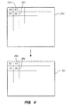
- Figure 5 shows one preferred way to form the N-tone image of the first preferred embodiment.
- Figure 6 shows one preferred way to generate sub-pixels and segments in the first preferred embodiment.
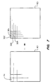
- Figure 7 shows the formation of sub-pixels in the first preferred embodiment.
- Figure 8 shows one preferred sets of segments for four sub-pixels.
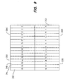
- Figure 9 shows the 16 levels printed using the different segments in Figure 8.
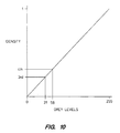
- Figure 10 shows the relationship between the grey levels and the density of each level in the N-tone image of the first preferred embodiment.
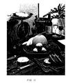
- Figure 11 shows a picture printed by the first preferred embodiment.
- Figure 12 shows an example for the second preferred embodiment, with 16 contiguous sub-pixels to form one pixel.
- Figure 13 shows the turn-on sequence of the sub-pixels to generate 13 different levels for the second preferred embodiment.
- Figure 14 shows one table of groups of grey levels for the second preferred embodiment.
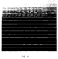
- Figure 15 shows the grey ramp generated based on the second preferred embodiment.
- Figure 16 shows a prior art grey ramp printed using a Bayer matrix.
- Figure 17 shows a part of a fourth preferred embodiment.
- Figure 18 shows a preferred way for the fourth preferred embodiment.
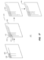
- Figure 19 shows graphically one preferred way to form the special dither matrix in the fourth preferred embodiment.
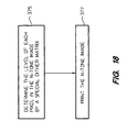
- Figure 20 shows a set of preferred steps to form the special matrix in Figure 19.
- The following description is directed solely to a method of generating an N-tone image. A system for generating such an image is not described in detail as suitable structures therefor will be immediately apparent to the skilled person from a reading of the method, be it by software, hardware or any combination thereof.
- Figure 1 shows a representation of a
preferred embodiment 100, which prints an N-tone image 102 by a printer, a plotter orother imprinting device 104 from agrey scale image 106. The N-tone image 102 has two intermediate forms, the first intermediate N-tone image 101 and the second intermediate N-tone image 103. The images have many pixels; for example, thegrey scale image 106 haspixels tone image 101 haspixels - Each pixel in the grey scale image has a level that is within a maximum and a minimum level. For example, the maximum level is 255 and the minimum level is 0; each level represents one grey level of the
grey scale image 106. - The first intermediate N-
tone image 101 has N levels, with N preferably greater than 2. The level of each pixel in the first intermediate N-tone image 101 is from one of the N levels. The N levels are selected from the grey levels in thegrey scale image 102 by dividing the grey levels into N groups. Each group of grey levels has a group maximum level, which is the maximum level in the group and is one of the N levels. The separations between adjacent levels in the N levels are non-uniform. The method to set the non-uniformity will be described later in the specification. - Figure 2 shows an example of a preferred table of groups of grey levels to generate a N-tone image with 16 levels. The
sixteenth group 202 covers the range of grey levels between 255 to 253 with its group maximum level being 255. Every group is represented by its group maximum level. The entire 16 groups give rise to 16 group maximum levels, which represent the 16 levels of the N-tone image. - The first preferred embodiment includes a number of
multi-level dither matrices 118, such as themulti-level dither matrix 122. Each multi-level dither matrix has many pixels, such as thematrix 122 haspixels - The multi-level dither matrices are formed through the groups of levels shown in Figure 2 and an original dither matrix. Figure 3 shows one
preferred way 260 to form amulti-level dither matrix 122 as the one shown in Figure 4. First, N groups of levels are formed, 262, as in Figure 2. Then the matrices are formed through scaling 264 the original dither matrix according to the groups of levels. Theoriginal dither matrix 250 may be a Bayer matrix or other types of dither matrix with levels ranging such as from 1 to 255; the matrix is the type that has been used extensively to render an image and will not be further described in this application. Themulti-level dither matrix 122 shown in Figure 4 corresponds to thefourth group 206 of grey levels shown in Figure 2, which covers the grey levels from 56 to 31. To form themulti-level dither matrix 122, the levels in the original dither matrix (1 to 255) are scaled according to the levels in thegroup 206, with grey levels ranging from 56 to 31; for example, thelevel 167 in the second pixel of the original dither matrix becomes thelevel 47 in the second pixel of the multi-level dither matrix using the following direct scaling calculation, with fractions rounded off:level 40 in thepixel 257 of the original dither matrix becomes 35 in thepixel 259 of the multi-level dither matrix. Based on the above method, themulti-level dither matrix 122 is formed. Using the original dither matrix and the 16 groups of grey levels shown in Figure 2, sixteen multi-level dither matrices are generated by the direct scaling calculations. Figure 5 shows a set of preferred steps to form the N-tone image, based on the multi-level dither matrices. - To generate the first intermediate N-
tone image 101, every pixel in thegrey scale image 106 is compared to and thresholded by a pixel in one of the multi-level dither matrices. For example, thefirst pixel 108 in thegrey scale image 106 has the grey level 51. This grey level falls within the fourth group of grey levels shown in Figure 2. Themulti-level dither matrix 122, generated by the fourth group of grey level, is selected, 275. The first pixel of the grey scale image is then compared, 277, to the first pixel of themulti-level dither matrix 122. In the comparison process, first, one decides if the level of the pixel in the grey scale image is larger than or equal to the level in the corresponding pixel of the multi-level dither matrix; if it is, the group maximum level of the corresponding group generating the multi-level dither matrix is chosen for the first intermediate N-tone image; however, if the level of the pixel in the grey scale image is smaller, the group maximum level of the subsequent group is chosen for the first intermediate N-tone image. In the present example, with 51 bigger than 50, the group maximum level, 56, is chosen to be the level of the first pixel in the first intermediate N-tone image. For the second pixel, with 46 less than 47, the group maximum level of the subsequent group, 31, is chosen to be the level in the N-tone image. From the levels in the grey scale image and the multi-level dither matrices, the pixel-to-pixel comparison method, as described above, generates the first intermediate N-tone image 101. - The second intermediate N-
tone image 103 is generated by two steps. First, each pixel in the first intermediate N-tone image 101 is represented or modelled, 279, by a number of contiguous sub-pixels, and then each sub-pixel is represented or modelled by a number of segments. - While not wishing to be bounded by theory, it is believed that some of the advantageous results of the preferred embodiment are obtained through understanding the functionality of relatively low-cost printers. To generate an image with substantially imperceptible dots, every pixel is printed by, for example, a laser printer with a resolution of at least 600 pixels or dots-per-inch. The characteristics of each pixel is preferably controlled through a pulse with a pulse width. The pulse width can be sub-divided into a number of segments. Each segment can be at a high or a low intensity; at a high intensity means that the segment is dark or that the segment is turned on with the pulse width extending into the segment; and at a low intensity means the segment is light or the segment is turned off with the pulse width not extending into the segment. For a typical present-day 600 dots-per-inch laser printer, if the pulse is divided into eight segments, it is preferable to have more than one segment at a high intensity to generate a reproducible output. In other words, every segment at a high intensity preferably should have a neighboring segment also at a high intensity. Based on this representation, different levels of the image require different pulse widths or require selecting different number of segments. In order to generate more levels for the output image, every pixel in the N-tone image is represented or modelled by a number of pixels; the number of pixels is designated as sub-pixels. In one preferred embodiment, by combining four sub-pixels to generate different levels for each pixel, one gets N-tone images with a 300 dots-per-inch resolution; the N-tone images generated have substantially imperceptible dots for the unaided eyes of an ordinary person, with 20/20 vision, under normal condition. The above theory also applies to other relatively low-cost printers, such as ink-jet printers, by varying the intensity of each printed dot in a way similar to varying the pulse width in each pixel of a laser printer. Then, using the method described herein, it is possible to generate images with substantially imperceptible dots.
- One example of using sub-pixels and segments is illustrated in Figures 7 and 8, with a set of preferred steps shown in Figure 6. The example is based on a laser printer with 600 sub-pixels or dots-per-inch. Figure 7 shows each pixel in the first intermediate N-
tone image 101 being replaced, 283, by four contiguous sub-pixels; for example, thepixel 114 is replaced by the sub-pixels 302, 304, 306 and 308. Figure 8 shows the four sub-pixels, with each sub-pixel replaced, 285, by eight segments. There is a number within each segment; for example, thesegment 310 has a number of 15, and thesegment 312 has a number of 1. The number inside the segment represents the level of the pixel when the segment is turned on or is at the high intensity. For example, for thelevel 15, the pulse width extends across three segments, thesegment level 1, the darkest level, the pulse width extends across all the segments; and for the level 16, no segment is turned on or all segments are at the low intensity. Thus, the level of each pixel is represented, 287, by the segments and the sub-pixels. - The sixteen levels have perceptibly different levels of grey. One preferred way to decide which segment to be turned on for which level is based on one's visual perception. In the embodiment shown in Figure 8 with 32 segments, the segments are turned on one after the other, with the level created measured by a densitometer, which measures the density of a level. Theoretically, there could be 33 levels from the 32 segments, but many levels are visually indistinguishable. Those indistinguishable levels are grouped as one level, for example the numerous segments grouped together for
level 1 andlevel 2. In this embodiment, sixteen distinguishable levels are selected. Another observation in the preferred embodiment using 600 sub-pixels or dots-per-inch laser printers is that thelightest level 15 preferably needs more than 1 segment. The effect of a segment turned on by itself without any neighboring segments being turned on may not be very reproducible. Thus, the lightest level preferably needs more than one segment to be turned on. However, once there are segments turned on, subsequent levels may only need one additional segment to be perceptibly different. For example, thelevel 14 only has one more segment turned on, as compared to thelevel 15. In this embodiment, the number of segments between levels is not uniform; for example, the difference betweenlevels 16 and 15 is 3 segments, and the difference betweenlevels - Another preferred way to decide which segment to be turned on for which level is to retain the 33 levels for the 32 segments. A number of levels may not be visually distinguishable, and one needs 6 bits to designate all the levels. If the number of bits is of concern, one may remove one level, and then only 5 bits would be needed to designate the 32 levels.
- The above example is based on a 600 sub-pixels or dots-per-inch laser printer. A laser printer with higher resolution can be used. The number of sub-pixels for each pixel does not have to be 4. The number of segments for each sub-pixel does not have to be 8. By experimenting with the number of segments, the number of sub-pixels and the dot size, one, based on the teachings in the present disclosure, can generate images with substantially imperceptible dots, with a different resolution, a different number of sub-pixels and a different number of segments.
- Figure 9 shows the 16 levels printed out using the different pulse widths or segments shown in Figure 8. For example, the fourth square block, 325, is the fourth level. As shown in Figure 8, all the
segments having number 4 or higher in it will be turned on, which means that pulses are turned on for three sub-pixels, 304, 304 and 306; in other words, 24 of the 32 segments are turned on. - The 16 levels shown in Figure 9 are measured by the densitometer. The density of each level of the N-tone image is related back to the grey levels of the grey scale image. In one preferred embodiment, the relationship is assumed to be linear. Figure 10 shows the relationship between the grey levels and the density of each level of the N-tone image. Each level in Figure 9 is mapped to a group or a range of grey levels. For example, the fourth level approximately has a grey level of 56, and the third level has 31; so the fourth group of levels covers the grey levels from 56 to 31. This is one preferred method to determine all the groups of grey levels in Figure 2.
- From the second intermediate N-
tone image 103, the N-tone image 102 is printed, 281, by theprinter 104. In the present embodiment, one way to represent a segment being turned on is to use a value of 1, and a segment being turned off by a value of 0. The segments with 1 in them will be printed. Figure 11 shows a picture printed out by the first preferred embodiment. The image has 300 dots or pixels per inch. Each pixel is represented by 4 sub-pixels, and each sub-pixel by 8 segments. There are altogether 32 segments for each pixel. In this embodiment, each pixel only has 16 levels, which can be represented by 4 bits. Thus, with an increase of 4 bits for every pixel, for an ordinary person, the figure generated has substantially imperceptible dots. Any dots in the figure, such as those on the apple, are in the original grey scale image. - A second preferred embodiment is similar to the first except one does not have to vary the pulse width, or use different segments for each sub-pixel in the second
intermediate dither matrix 103. The N-tone image is generated, for example, through an original Bayer matrix with 8 by 8 pixels. - In one example of the second embodiment, every pixel is represented or modelled by 16 contiguous sub-pixels, as shown in Figure 12. Figure 13 shows the turn-on sequence of the sub-pixels to generate 13 different levels. For example, if one prefers the fourth level, every sub-pixel labelled 4 or higher will be turned on, or will have a dot printed in it. This turn-on sequence is determined based on a classical screen or cluster dot at 45° model; such model should be obvious to those skilled in the art and will not be further described here. From the 13 levels, a densitometer generates 13 groups of levels according to a graph similar to Figure 10. Figure 14 shows the groups of levels found. Again, the separations between the groups of levels are not uniform.
- From the 13 groups of levels in Figure 14, the original Bayer matrix forms 13 multi-level dither matrices. From the multi-level dither matrices, the first
intermediate dither matrix 101 is generated. Based on the 13 levels as shown in Figure 13, the second intermediate N-tone image and the N-tone image are produced as in the first preferred embodiment. - Figure 15 shows the grey ramp with 256 grey levels generated based on the second preferred embodiment with multi-level Bayer matrices and the 13 levels. The pixels have a resolution of 75 dots-per-inch, and the sub-pixels at 300 dots-per-inch. Figure 16 shows a prior art grey ramp at 300 dots-per-inch with 256 levels, printed using a Bayer matrix with 8 by 8 pixels. The grey ramp in Figure 15 has significantly more distinguishable grey levels than the grey ramp in Figure 16. Moreover, the transition between grey levels in Figure 15 are more smooth than those in Figure 16. These effects are more obvious to a viewer if the two figures are viewed side-by-side at a distance, such as 60 centimetres (2 feet) away from the viewer.
- For a third preferred embodiment, its main difference from the first preferred embodiment is that the multi-level dither matrices are replaced by a multi-levelling error diffusion technique to generate the first intermediate N-
tone image 101. In the normal error diffusion technique, the error from each pixel is compared to the middle grey scale level of the grey scale image, with the errors diffused to its surrounding pixels. Error diffusion techniques are well-known to those with ordinary skill in the art and will not be further described in the specification. For the preferred multi-level error diffusion technique, the level in each grey scale image pixel again maps to a corresponding group of grey levels, such as the one shown in Figure 2. The level in each pixel of the grey scale image is compared to the middle level of its corresponding group of levels, and the error is again diffused to its corresponding pixels to generate the first intermediate N-tone image 101. For example, thefirst pixel 108 with a level of 51 is compared to the level 43 (the average of 56 and 31), and the error is diffused to its neighbors. - Figure 17 shows a portion of a fourth
preferred embodiment 401, with a set of preferred steps shown in Figure 18. The difference between the first and the fourth embodiment is that the fourth embodiment reduces the number of steps in the first embodiment by collapsing many steps into one special dither matrix. In this embodiment, the level of each segment in a second intermediate N-tone image 404 is determined by a pixel-to-pixel comparison between thegrey scale image 400 and thespecial dither matrix 402. Based on the comparisons, the level in each pixel of the N-tone image is determined, 375. Then, from the second intermediate N-tone image 404, the N-tone image is printed, 377, by the printer. In another embodiment, one preferably does not need to determine, 375, the level in each pixel. All the segments in the second intermediate N-tone image 404 are sent as a bit map to theprinter 404, and the bit map is printed directly. - In one preferred embodiment, as shown in Figure 17, every pixel in the
grey scale image 400 is subdivided into a group of contiguous segments to form a finer-resolutiongrey scale image 406. All the segments for each pixel may have the same grey level as its corresponding pixel in thegrey scale image 400; for example, thefirst pixel 408 with a level of 206 is subdivided into thirty-two contiguous segments, such as 410, 412, 414 and 416; all the segments have the level of 206. For another embodiment, the finer-resolutiongrey scale image 406 actually has a finer resolution than thegrey scale image 400; for example, thirty-two times higher in resolution. After the sub-division, each segment in the finer-resolution grey scale image is compared to its corresponding segment in thespecial dither matrix 402. - Figure 19 graphically shows one preferred way to form the
special dither matrix 402, with a set of preferred steps shown in Figure 20. As an overview, many standard grey scale images, such as 460, 462 and 464, are first compared, 500, to the multi-level dither matrices, such as 118 and 122, to produce many intermediate output matrices, such as 450, 452 and 454. Then, every pixel in the intermediate output matrices is replaced by a group of contiguous sub-pixels as in the first preferred embodiment to form, 502, many output matrices, such as 470, 472 and 474. All the output matrices are added, 504, together to form thespecial dither matrix 402. - In more detail, every pixel in each standard grey scale image has the same grey level. For example, all the pixels in the standard
grey scale image 460 has thegrey level 0. The grey scale image may have 256 levels. In order to cover all the levels, there are preferably 256 standard grey scale images. - The multi-level dither matrices are generated as in the first preferred embodiment. For each standard grey scale image, its pixels are compared to one corresponding multi-level dither matrix to generate its intermediate output matrix. The comparison is similar to the comparison in the first preferred embodiment. For example, the standard
grey scale image 462 has the level of 45 for all its pixels. Its corresponding multi-level dither matrix is 122, which covers the levels from 56 to 31. Thus, every pixel in the standardgrey scale image 462 is compared to its corresponding pixel in themulti-level dither matrix 122 to generate theintermediate output matrix 452. - All the intermediate output matrices are transformed to their corresponding output matrices by replacing every pixel with a group of contiguous segments. This replacement process is similar to the replacement process in generating the second intermediate N-tone image from the first intermediate N-tone image in the first embodiment. For example, each pixel in the intermediate output matrices is replaced by 32 segments with their corresponding intensity to represent the level of each pixel; the segments that should be turned on have one in them, and those that should be turned off have zero. After the replacement, every intermediate output matrix becomes its corresponding output matrix. For example, the
intermediate output matrix 452 becomes the output matrices are then added together by matrix addition to produce thespecial dither matrix 402. - A Bayer matrix may be used for the fourth preferred embodiment. The difference is that every pixel in the intermediate output matrix is not replaced by segments, but by sub-pixels only, as in the second preferred embodiment. A sub-pixel that should be turned on has one in it and the one that should be off has a zero in it.
- It is therefore, possible to generate visually pleasing N-tone images in a relatively inexpensive manner. The above-described embodiment can be modified for color images. For a color N-tone image, the methods are repeated at least two more times, each time for a different color to generate the color N-tone image. They can also be used for a display with the N-tone image shown on the display, instead of printed on a printer. In fact, the printing step described above includes displaying, with the printer being a display.
Claims (7)
- A method of generating a N-tone image (102) from a grey scale image (106), both images being formed from a plurality of pixels, each pixel in the grey scale image (106) having a grey level within maximum and minimum levels, and each pixel in the N-tone image (102 having one of N levels with N bigger than two and less than the number of grey levels available for the grey scale image, the method comprising the steps of determining (275, 277) the level of each pixel in the N-tone image based on the level of its corresponding pixel in the grey scale image, and employing a plurality of scaled multilevel dither matrices based on a technique selected from the list of (1) a technique based on an original dither matrix and (2) an error diffusion technique ; modeling (279) every pixel by replacing it with a plurality of sub-pixels, and every sub-pixel with a plurality of segments, each segment having an intensity whose value depends on the level of the pixel; and printing (289) the N-tone image on the basis of modeled pixels such that N substantially reproducible levels can be generated for each pixel by its corresponding segments, each with its corresponding intensity and wherein the difference in the number of segments with a certain intensity representing adjacent levels is not uniform and wherein the N-tone image (102) is generated by a laser printer (104); and the step of modeling (279) includes using a pulse for each sub-pixel, the pulse having a width related to the intensity of each segment for its corresponding sub-pixel.
- A method as recited in claim 1, wherein the N-tone image has substantially imperceptible dots produced by the non-uniformity.
- A method as recited in claim 1 or 2, wherein the N-tone image (102) has a resolution approximately equal to or greater than 300 pixels or dots-per-inch.
- A method as recited in any preceding claim, wherein each pixel (114) is represented by four sub-pixels (302, 304); and each sub-pixel (302) is represented by eight segments (314, 316).
- A method as recited in any preceding claim, wherein the step of determining (275, 277) the level is based on a Bayer matrix.
- A method as recited in any preceding claim, wherein the intensity of each segment is selected from the list of (1) a high intensity and (2) a low intensity, such that every segment at a high intensity has an adjacent segment which is also at a high intensity.
- A system for generating a N-tone image (102) from a grey scale image (106), both images being formed from a plurality of pixels, each pixel in the grey scale image (106) having a grey level within maximum and minimum levels, and each pixel in the N-tone image (102) having one of N levels with N bigger than two and less than the number of grey levels available for the grey scale image, the system comprising determining means (275, 277) for determining the level of each pixel in the N-tone image based on the level of its corresponding pixel in the grey scale image, and employing a plurality of scaled multilevel dither matrices based on a technique selected from the list of (1) a technique based on an original dither matrix and (2) an error diffusion technique; modeling means (279) for modeling every pixel by replacing it with a plurality of sub-pixels, and every sub-pixel with a plurality of segments, each segment having an intensity whose value depends on the level of the pixel; and printing means (189) for printing the N-tone image on the basis of modeled pixels such that N substantially reproducible levels can be generated for each pixel by its corresponding segments, each with its corresponding intensity and wherein the difference in the number of segment with a certain intensity representing adjacent levels is not uniform and wherein the N-tone image (102) is generated by a laser printer (104); and wherein the modeling means (279) are adapted to use a pulse for each sub-pixel, the pulse having a width related to the intensity of each segment for its corresponding sub-pixel.
Applications Claiming Priority (2)
| Application Number | Priority Date | Filing Date | Title |
|---|---|---|---|
| US20521594A | 1994-03-02 | 1994-03-02 | |
| US205215 | 1994-03-02 |
Publications (2)
| Publication Number | Publication Date |
|---|---|
| EP0670653A1 EP0670653A1 (en) | 1995-09-06 |
| EP0670653B1 true EP0670653B1 (en) | 2001-07-11 |
Family
ID=22761295
Family Applications (1)
| Application Number | Title | Priority Date | Filing Date |
|---|---|---|---|
| EP95300985A Expired - Lifetime EP0670653B1 (en) | 1994-03-02 | 1995-02-16 | Multiple tone image generation |
Country Status (5)
| Country | Link |
|---|---|
| US (1) | US5615021A (en) |
| EP (1) | EP0670653B1 (en) |
| JP (1) | JPH07283943A (en) |
| CN (1) | CN1085000C (en) |
| DE (1) | DE69521638T2 (en) |
Families Citing this family (12)
| Publication number | Priority date | Publication date | Assignee | Title |
|---|---|---|---|---|
| DE69527675T2 (en) * | 1994-04-27 | 2003-04-03 | Agfa Gevaert Nv | Multi-level halftone screening with grouped dots and lines for electrographic color printing |
| US5768425A (en) * | 1995-07-14 | 1998-06-16 | Texas Instruments Incorporated | Method and system for improved threshold based screening |
| US5751470A (en) * | 1996-03-12 | 1998-05-12 | Lexmark International, Inc. | Method for enhanced print quality on print engines with at least one high resolution dimension |
| JP4348748B2 (en) * | 1996-07-18 | 2009-10-21 | セイコーエプソン株式会社 | Printing apparatus and image recording method |
| US5966507A (en) * | 1997-08-25 | 1999-10-12 | Hewlett-Packard Company | Image resolution enhancement technology (IRET) for dual dye-load inkjet printer |
| US6643032B1 (en) * | 1998-12-28 | 2003-11-04 | Xerox Corporation | Marking engine and method to optimize tone levels in a digital output system |
| US6264300B1 (en) * | 1999-06-04 | 2001-07-24 | Lexmark International, Inc. | Methods of printing with an ink jet printer using inks with same hue and different saturation |
| US6778299B2 (en) | 2001-03-09 | 2004-08-17 | Hewlett-Packard Development Company, L.P. | Error diffusion with partial dots method and system |
| CN100435548C (en) * | 2006-09-15 | 2008-11-19 | 北京大学 | Method and device for generating multi-site modulating web site simultaneouslly |
| EP2123017A1 (en) * | 2007-03-02 | 2009-11-25 | Marvell World Trade Ltd | Dynamic image dithering |
| JP4549418B2 (en) * | 2008-03-04 | 2010-09-22 | シャープ株式会社 | Image processing apparatus, image processing method, image forming apparatus, program, and recording medium |
| EP3461116B1 (en) * | 2017-09-23 | 2024-04-17 | Heidelberg Polska Sp. z o.o. | A method and system for am screening and protecting printouts |
Family Cites Families (18)
| Publication number | Priority date | Publication date | Assignee | Title |
|---|---|---|---|---|
| US4455562A (en) * | 1981-08-14 | 1984-06-19 | Pitney Bowes Inc. | Control of a light emitting diode array |
| JPS60240277A (en) * | 1984-05-15 | 1985-11-29 | Fuji Xerox Co Ltd | Intermediate gradation recording method |
| DE3609252A1 (en) | 1985-03-20 | 1986-10-02 | Canon K.K., Tokio/Tokyo | METHOD AND DEVICE FOR IMAGE REPRODUCTION |
| US4974067A (en) * | 1986-06-06 | 1990-11-27 | Ricoh Company, Ltd. | Multi-step-digital color image reproducing method and apparatus |
| US4680645A (en) * | 1986-08-25 | 1987-07-14 | Hewlett-Packard Company | Method for rendering gray scale images with variable dot sizes |
| JPS63286351A (en) * | 1987-05-19 | 1988-11-24 | Sony Corp | Printer |
| US5086484A (en) * | 1988-08-24 | 1992-02-04 | Canon Kabushiki Kaisha | Image processing apparatus with fixed or variable threshold |
| US5068926A (en) * | 1989-02-10 | 1991-12-03 | Kaneyuki Suzuki | Flush toilet |
| DE69027870T2 (en) * | 1989-02-10 | 1997-01-09 | Canon Kk | Image processing device |
| US5309526A (en) * | 1989-05-04 | 1994-05-03 | At&T Bell Laboratories | Image processing system |
| JPH0380767A (en) | 1989-08-24 | 1991-04-05 | Ricoh Co Ltd | Gradation recorder for image |
| US5111310A (en) * | 1990-12-04 | 1992-05-05 | Research Technologies Corporation, Inc. | Method and apparatus for halftone rendering of a gray scale image using a blue noise mask |
| US5387983A (en) * | 1991-09-27 | 1995-02-07 | Minolta Camera Kabushiki Kaisha | Facsimile apparatus comprising converting means for converting binary image data into multi-value image data and image processing apparatus judging pseudo half-tone image |
| US5303069A (en) * | 1991-12-19 | 1994-04-12 | Camex, Inc. | Method for producing a multitone image |
| US5341224A (en) * | 1992-04-17 | 1994-08-23 | Xerox Corporation | Image processing system and method for employing adaptive scanning of halftones to provide better printable images |
| JPH05336373A (en) * | 1992-06-04 | 1993-12-17 | Toshiba Corp | Image recorder |
| US5278670A (en) * | 1992-12-18 | 1994-01-11 | Xerox Corporation | Content-based resolution conversion of color documents |
| DE69520703T2 (en) | 1994-03-02 | 2001-08-02 | Hewlett Packard Co | Generation of multi-tone images |
-
1995
- 1995-02-16 DE DE69521638T patent/DE69521638T2/en not_active Expired - Fee Related
- 1995-02-16 EP EP95300985A patent/EP0670653B1/en not_active Expired - Lifetime
- 1995-02-27 CN CN95100825A patent/CN1085000C/en not_active Expired - Fee Related
- 1995-03-01 JP JP7065249A patent/JPH07283943A/en active Pending
- 1995-06-02 US US08/459,143 patent/US5615021A/en not_active Expired - Lifetime
Also Published As
| Publication number | Publication date |
|---|---|
| EP0670653A1 (en) | 1995-09-06 |
| CN1085000C (en) | 2002-05-15 |
| CN1118903A (en) | 1996-03-20 |
| DE69521638T2 (en) | 2001-10-25 |
| JPH07283943A (en) | 1995-10-27 |
| US5615021A (en) | 1997-03-25 |
| DE69521638D1 (en) | 2001-08-16 |
Similar Documents
| Publication | Publication Date | Title |
|---|---|---|
| EP0670654B1 (en) | Multiple tone image generation | |
| JP3381755B2 (en) | Method and apparatus for improved adaptive filtering and thresholding to reduce image graininess | |
| US5317418A (en) | Halftone images using special filters | |
| EP0741486B1 (en) | Moiré free multilevel halftoning of color images | |
| EP0591274B1 (en) | Improved error diffusion system | |
| EP0892549B1 (en) | Method and apparatus for reproducing an image with gray level printing | |
| US20010030769A1 (en) | Apparatus and method for halftone hybrid screen generation | |
| US5515456A (en) | Process for providing digital halftone image with random error diffusion, color correction and enlargement | |
| US5258850A (en) | Line screen design for gray scale rendering | |
| EP0405052A2 (en) | A technique for producing a fine grained dithered halftone image having an increased number of gray levels | |
| EP0670653B1 (en) | Multiple tone image generation | |
| JPH0774950A (en) | Generating method for half-tone picture using modeling of print symbol | |
| EP0977424B1 (en) | Halftone printing using donut filters | |
| JPH0785273A (en) | Frequency-modulated halftone image and formation method | |
| US6266157B1 (en) | Method of error diffusion using 2×2 color correction and increment matching | |
| US20040113958A1 (en) | Sub-dot phase modulation for computer to plate inkjet system | |
| CA2313774C (en) | Method and apparatus for producing threshold arrays using variance minimization and pixel angle calculations | |
| EP0772934B1 (en) | Image display using evenly distributed intensity clusters | |
| KR100561372B1 (en) | The method of designing clustered-dot screen based on the human visual characteristics and the printer model, the device thereof and the image forming device outputing binary image using the designed screen | |
| JP2002514858A (en) | Halftone image reproducing method and system by automatic gamma correction | |
| US5689344A (en) | Mitigation of tenting deletions in color xerographic printers | |
| US7911646B2 (en) | Multilevel halftoning for tint graphic, line art and text rendering | |
| EP0712235B1 (en) | Pixel pair grid halftoning for a hyperacuity printer | |
| EP1401190A2 (en) | Sub dot phase modulation for computer to plate inkjet system | |
| US5446561A (en) | Method and apparatus for digital scale halftoning with variable screen structure for electrophotographic printing devices |
Legal Events
| Date | Code | Title | Description |
|---|---|---|---|
| PUAI | Public reference made under article 153(3) epc to a published international application that has entered the european phase |
Free format text: ORIGINAL CODE: 0009012 |
|
| AK | Designated contracting states |
Kind code of ref document: A1 Designated state(s): DE FR GB |
|
| 17P | Request for examination filed |
Effective date: 19951127 |
|
| 17Q | First examination report despatched |
Effective date: 19990426 |
|
| GRAG | Despatch of communication of intention to grant |
Free format text: ORIGINAL CODE: EPIDOS AGRA |
|
| GRAG | Despatch of communication of intention to grant |
Free format text: ORIGINAL CODE: EPIDOS AGRA |
|
| GRAH | Despatch of communication of intention to grant a patent |
Free format text: ORIGINAL CODE: EPIDOS IGRA |
|
| GRAH | Despatch of communication of intention to grant a patent |
Free format text: ORIGINAL CODE: EPIDOS IGRA |
|
| RAP1 | Party data changed (applicant data changed or rights of an application transferred) |
Owner name: HEWLETT-PACKARD COMPANY, A DELAWARE CORPORATION |
|
| GRAA | (expected) grant |
Free format text: ORIGINAL CODE: 0009210 |
|
| AK | Designated contracting states |
Kind code of ref document: B1 Designated state(s): DE FR GB |
|
| REF | Corresponds to: |
Ref document number: 69521638 Country of ref document: DE Date of ref document: 20010816 |
|
| ET | Fr: translation filed | ||
| REG | Reference to a national code |
Ref country code: GB Ref legal event code: IF02 |
|
| PLBE | No opposition filed within time limit |
Free format text: ORIGINAL CODE: 0009261 |
|
| STAA | Information on the status of an ep patent application or granted ep patent |
Free format text: STATUS: NO OPPOSITION FILED WITHIN TIME LIMIT |
|
| 26N | No opposition filed | ||
| PGFP | Annual fee paid to national office [announced via postgrant information from national office to epo] |
Ref country code: GB Payment date: 20070223 Year of fee payment: 13 |
|
| PGFP | Annual fee paid to national office [announced via postgrant information from national office to epo] |
Ref country code: DE Payment date: 20070330 Year of fee payment: 13 |
|
| PGFP | Annual fee paid to national office [announced via postgrant information from national office to epo] |
Ref country code: FR Payment date: 20070221 Year of fee payment: 13 |
|
| GBPC | Gb: european patent ceased through non-payment of renewal fee |
Effective date: 20080216 |
|
| REG | Reference to a national code |
Ref country code: FR Ref legal event code: ST Effective date: 20081031 |
|
| PG25 | Lapsed in a contracting state [announced via postgrant information from national office to epo] |
Ref country code: DE Free format text: LAPSE BECAUSE OF NON-PAYMENT OF DUE FEES Effective date: 20080902 |
|
| PG25 | Lapsed in a contracting state [announced via postgrant information from national office to epo] |
Ref country code: FR Free format text: LAPSE BECAUSE OF NON-PAYMENT OF DUE FEES Effective date: 20080229 |
|
| PG25 | Lapsed in a contracting state [announced via postgrant information from national office to epo] |
Ref country code: GB Free format text: LAPSE BECAUSE OF NON-PAYMENT OF DUE FEES Effective date: 20080216 |