EP0677946A2 - Data transfer control method and information processing system using the same - Google Patents
Data transfer control method and information processing system using the same Download PDFInfo
- Publication number
- EP0677946A2 EP0677946A2 EP95302506A EP95302506A EP0677946A2 EP 0677946 A2 EP0677946 A2 EP 0677946A2 EP 95302506 A EP95302506 A EP 95302506A EP 95302506 A EP95302506 A EP 95302506A EP 0677946 A2 EP0677946 A2 EP 0677946A2
- Authority
- EP
- European Patent Office
- Prior art keywords
- processing
- input
- image data
- data
- processing apparatus
- Prior art date
- Legal status (The legal status is an assumption and is not a legal conclusion. Google has not performed a legal analysis and makes no representation as to the accuracy of the status listed.)
- Granted
Links
Images


Classifications
-
- H—ELECTRICITY
- H04—ELECTRIC COMMUNICATION TECHNIQUE
- H04N—PICTORIAL COMMUNICATION, e.g. TELEVISION
- H04N1/00—Scanning, transmission or reproduction of documents or the like, e.g. facsimile transmission; Details thereof
- H04N1/32—Circuits or arrangements for control or supervision between transmitter and receiver or between image input and image output device, e.g. between a still-image camera and its memory or between a still-image camera and a printer device
- H04N1/333—Mode signalling or mode changing; Handshaking therefor
- H04N1/33361—Mode signalling or mode changing; Handshaking therefor according to characteristics or the state of the communication line
-
- H—ELECTRICITY
- H04—ELECTRIC COMMUNICATION TECHNIQUE
- H04N—PICTORIAL COMMUNICATION, e.g. TELEVISION
- H04N1/00—Scanning, transmission or reproduction of documents or the like, e.g. facsimile transmission; Details thereof
- H04N1/32—Circuits or arrangements for control or supervision between transmitter and receiver or between image input and image output device, e.g. between a still-image camera and its memory or between a still-image camera and a printer device
- H04N1/333—Mode signalling or mode changing; Handshaking therefor
- H04N1/33307—Mode signalling or mode changing; Handshaking therefor prior to start of transmission, input or output of the picture signal only
- H04N1/33315—Mode signalling or mode changing; Handshaking therefor prior to start of transmission, input or output of the picture signal only reading or reproducing mode only, e.g. sheet size, resolution
-
- H—ELECTRICITY
- H04—ELECTRIC COMMUNICATION TECHNIQUE
- H04N—PICTORIAL COMMUNICATION, e.g. TELEVISION
- H04N1/00—Scanning, transmission or reproduction of documents or the like, e.g. facsimile transmission; Details thereof
- H04N1/32—Circuits or arrangements for control or supervision between transmitter and receiver or between image input and image output device, e.g. between a still-image camera and its memory or between a still-image camera and a printer device
- H04N1/333—Mode signalling or mode changing; Handshaking therefor
- H04N1/33307—Mode signalling or mode changing; Handshaking therefor prior to start of transmission, input or output of the picture signal only
- H04N1/33323—Mode signalling or mode changing; Handshaking therefor prior to start of transmission, input or output of the picture signal only transmission mode only, e.g. speed
-
- H—ELECTRICITY
- H04—ELECTRIC COMMUNICATION TECHNIQUE
- H04N—PICTORIAL COMMUNICATION, e.g. TELEVISION
- H04N2201/00—Indexing scheme relating to scanning, transmission or reproduction of documents or the like, and to details thereof
- H04N2201/32—Circuits or arrangements for control or supervision between transmitter and receiver or between image input and image output device, e.g. between a still-image camera and its memory or between a still-image camera and a printer device
- H04N2201/333—Mode signalling or mode changing; Handshaking therefor
- H04N2201/33307—Mode signalling or mode changing; Handshaking therefor of a particular mode
- H04N2201/33342—Mode signalling or mode changing; Handshaking therefor of a particular mode of transmission mode
- H04N2201/3335—Speed or rate
-
- H—ELECTRICITY
- H04—ELECTRIC COMMUNICATION TECHNIQUE
- H04N—PICTORIAL COMMUNICATION, e.g. TELEVISION
- H04N2201/00—Indexing scheme relating to scanning, transmission or reproduction of documents or the like, and to details thereof
- H04N2201/32—Circuits or arrangements for control or supervision between transmitter and receiver or between image input and image output device, e.g. between a still-image camera and its memory or between a still-image camera and a printer device
- H04N2201/333—Mode signalling or mode changing; Handshaking therefor
- H04N2201/33307—Mode signalling or mode changing; Handshaking therefor of a particular mode
- H04N2201/33342—Mode signalling or mode changing; Handshaking therefor of a particular mode of transmission mode
- H04N2201/33357—Compression mode
Definitions
- the present invention relates to an information processing system including at least an input apparatus and a processing apparatus, an information processing apparatus used in the system, and a data transfer control method in a network.
- a plurality of apparatuses especially, a scanner apparatus, a printer apparatus, a facsimile device, and a management apparatus for managing these apparatuses, are connected to a network, and the entire network operates as one system.
- the conventional network system has poor data transfer efficiency when a read image is transmitted to another processing apparatus on the network.
- an object of the present invention to provide an information processing system and an information processing apparatus, which can control communications in correspondence with the communication state in a network.
- an information processing system having an input apparatus capable of inputting image data and transmitting the input image data, a processing apparatus capable of processing a received image, and a network to which the input and processing apparatuses are connected, the system realizing a function for inputting and processing image data as a whole, comprising: control means for controlling to transmit image data input by the input apparatus divisionally or simultaneously in correspondence with a communication state in the network.
- an information processing apparatus connected to a network, for exchanging image data with the network, comprising: means for inputting image data; means for detecting a communication state in the network; and control means for controlling to transmit image data input by the input means divisionally or simultaneously onto the network in correspondence with the detected communication state.
- control means controls transmission in correspondence with a data traffic in the network.
- control means is included in the input apparatus.
- the input apparatus comprises an image input/output apparatus for reading an image, and outputting the read image.
- the control means detects a communication state, and controls the input apparatus to transmit a portion or the entire page of a read original image in correspondence with the detected communication state.
- the input apparatus comprises a reading device which reads an original, the control means detects a communication state, and controls the input apparatus to transmit read image data of originals in units of unitary page or in units of a plurality of pages.
- an information processing system having an input apparatus capable of inputting image data and transmitting the input image data, a processing apparatus capable of processing a received image, and a network to which the input and processing apparatuses are connected, the system realizing a function for inputting and processing image data as a whole, comprising: control means for setting a different transmission sequence of image data from the input apparatus to the processing apparatus in correspondence with a processing manner of image data on the processing apparatus side.
- an information processing apparatus which is connected to a network, and exchanges image data with the network, comprising: means for inputting image data; and control means for transmitting designation information for designating a processing manner in a processing apparatus which processes input image data to the processing apparatus, and controlling to divisionally or simultaneously transmit image data input by the input means in correspondence with a processing manner.
- control means determines the processing manner of image data on the processing apparatus side in the input apparatus, and informs the determination result to the processing apparatus side.
- control means is arranged in the input apparatus.
- the processing manner of image data on the processing apparatus side is defined such that an image input operation in the input apparatus and processing of image data in the processing apparatus are substantially simultaneously performed.
- the processing manner of image data on the processing apparatus side is defined such that processing of image data in the processing apparatus is started after an image input operation in the input apparatus is completed.
- the processing manner of image data on the processing apparatus side is defined such that processing of image data in the processing apparatus is started at a time different from an input time of an image in the input apparatus.
- the input apparatus comprises an image reading device
- the processing apparatus comprises a facsimile device.
- the processing manner is an immediate transmission mode
- the control means transfers image data to the processing apparatus in units of lines.
- the processing manner is a timer transmission mode
- the control means simultaneously transfers image data stored in a buffer and transmission time data to the processing apparatus.
- the processing manner is a buffer transmission mode
- the control means simultaneously transfers image data stored in a buffer to the processing apparatus.
- an information processing system which comprises an input apparatus capable of inputting image data and transmitting the input image data, a processing apparatus capable of processing a received image, and a network to which the input and processing apparatuses are connected, the system realizing a function for inputting and processing image data as a whole, comprising: control means for controlling a format of image data to be output from the input apparatus to the processing apparatus on the basis of a matching state between characteristics of image data processed by the input apparatus and characteristics of image data processed by the processing apparatus.
- an information processing apparatus which is connected to a network, and exchanges image data with the network, comprising: means for inputting image data; means for acquiring processing characteristics of image data in a processing apparatus for processing the image data from an external apparatus; and control means for controlling to divisionally or simultaneously transmit image data input by the input means in correspondence with a matching state between characteristics of image data of the input means, and the processing characteristics of image data in the processing apparatus.
- the matching state of the characteristics of image data is a matching state between compression methods of the input apparatus and the processing apparatus.
- the input apparatus comprises first compression means
- the processing apparatus comprises second compression means
- the control means disables the first compression means when a compression method of the first compression means is different from a compression method of the second compression means.
- the input apparatus comprises first compression means
- the processing apparatus comprises second compression means
- the control means enables the first compression means when a compression method of the first compression means is the same as a compression method of the second compression means.
- the processing apparatus comprises a computer, a facsimile communication modem, a printer, a file, and the like.
- an information processing system which comprises an input apparatus capable of inputting image data and transmitting the input image data, a processing apparatus capable of processing a received image, and a network to which the input and processing apparatuses are connected, the system realizing a function for inputting and processing image data as a whole, comprising: control means for controlling to divisionally or simultaneously transmit data input by the input apparatus in correspondence with a relationship between the input apparatus and the processing apparatus in the network.
- a data transfer control method between communication apparatuses in a network including a plurality of communication apparatuses comprising the steps of: detecting a busy rate of the network; and increasing/decreasing an amount of data which is a transfer unit in correspondence with the detected busy rate.
- a data transfer control method from a data input apparatus to a data processing apparatus in a network including the data input apparatus and the data processing apparatus comprising the steps of: detecting a time difference between an input time of data in the data input apparatus and a processing time of the data in the processing apparatus; and increasing/decreasing an amount of data which is a transfer unit in correspondence with the detected time difference.
- a data control method from a data input apparatus to a data processing apparatus in a network including the data input apparatus having a first pre-processing function and the data processing apparatus having a second pre-processing function equivalent to the first pre-processing function, comprising the steps of: discriminating a matching state between the first and second pre-processing functions, and informing a discrimination result to the data processing apparatus; and executing pre-processing in the input apparatus and transferring pre-processed data to the processing apparatus when the first and second pre-processing functions are the same, and transferring data before pre-processing to the processing apparatus when the first and second pre-processing functions are different from each other; and determining in accordance with the information in the processing apparatus whether or not the second pre-processing function is executed for the data sent from the data input apparatus.
- Fig. 1 is a block diagram showing the arrangement of an information processing system according to an embodiment of the present invention.
- this system constitutes a LAN (local area network) connected to a communication line (network) 4.
- An image reading device 10 for reading an image a printer apparatus 5 for printing an image on a paper sheet, a facsimile device 6 for transmitting or receiving an image via a telephone line, a file apparatus 7 for storing an image or reading out the stored image, and a computer apparatus 8 for receiving an image and editing the received image are connected to the communication line 4.
- These apparatuses are respectively assigned with identifiers indicating the types of apparatuses, and address numbers on the network.
- the image reading device 10 is classified as an image input apparatus
- the printer apparatus 5 is classified as an image output apparatus
- the facsimile device 6, the file apparatus 7, and the computer apparatus 8 are classified as image input/output apparatuses.
- the image reading device 10, the facsimile device 6, the file apparatus 6, and the computer apparatus 8 are also image input apparatuses.
- the image reading device has a reader 1 for reading an original image, and converting the read image into image data, a controller 2 for controlling image data from the reader 1, and an operation unit 3 which is connected to the controller 2 and used to designate an output method of image data from the reader 1.
- Fig. 2 is a sectional view showing the arrangement of the reader 1.
- Originals stacked on an original feeder 101 are fed onto an original table glass surface 102 one by one.
- a lamp 103 of a scanner is turned on, and a scanner unit 104 moves to irradiate light onto the original.
- Light reflected by the original is transmitted through a lens 108 via mirrors 105, 106, and 107 in turn, and thereafter, is input to a CCD image sensor unit (to be referred to as a CCD hereinafter) 109.
- a CCD image sensor unit to be referred to as a CCD hereinafter
- Fig. 3 is a block diagram showing the signal processing arrangement of the reader 1.
- Image information input to the CCD 109 is photoelectrically converted into electrical signals.
- Color information signals from the CCD 109 are amplified by amplifiers 110R, 110G, and 110B in correspondence with the input level of an A/D converter 111.
- Output signals from the A/D converter 111 are input to a shading circuit 112, and are subjected to correction of illumination nonuniformity of the lamp 103 and of sensitivity nonuniformity of the CCD 109.
- Output signals from the shading circuit 112 are input to a magnification circuit 113.
- the magnification circuit 113 attains magnification in the main scanning direction. Maginification in the sub-scanning direction is attained by changing the scanning speed of the scanner unit 104.
- An edge emphasis circuit 114 attains edge emphasis by emphasizing high-frequency components of signals from the magnification circuit 113.
- Output signals from the edge emphasis circuit 114 are output to the controller 2 via a connector 115.
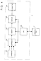
- Fig. 4 is a block diagram showing the controller 2 and the operation unit 3.
- a connector 120 includes a terminal for receiving image data from the reader 1. Signals input via the connector 120 are input to a compression circuit 121. An output signal from the compression circuit 121 is input to a memory 122. A signal output from the memory 122 is output onto the network 4 via a network interface 123 and a connector 124. A CPU 125 controls the overall controller 2 and receives information input from the operation unit 3.
- Fig. 5 shows the layout of buttons on the panel of the operation unit 3.
- a printer switch 31 for designating an output destination of an image read by the reader 1 to the printer apparatus 5
- a FAX switch 32 for designating an output destination of an image read by the reader 1 to the facsimile device 6, a ten-key pad 33, and the like are arranged.
- all the apparatuses connected to the network have a table representing the network configuration, as shown in Fig. 6.
- This table is configured in the order of addresses assigned to the apparatuses on the network 4, and stores an identification name of an apparatus assigned to the corresponding address value, the type of the apparatus (such as a facsimile device, a printer apparatus, and the like), and the attribute of the apparatus in units of apparatuses.
- a user of this system can designate an apparatus, from which image data read by the image reading device 10 is to be output, by depressing the switch 31 or 32 or by the identifier or address of the apparatus. For example, when image data is to be output via a printer, the user depresses the printer switch 31. When only one printer is connected to the system, the printer apparatus 5 is designated to be the output destination by only depressing the printer switch 31. If a plurality of apparatuses having printer attributes are connected to the network 4, a message, which indicates that a plurality of printers are connected and urges a user to select one of printers, is displayed on a display 34.
- a message urging a user to input the telephone number of a transmission destination appears on the display 34.
- the user inputs the telephone number of the transmission destination using the ten-key pad 33.
- the display 34 displays a message urging a user to designate a facsimile transmission mode.
- the transmission mode includes an immediate transmission mode for immediately performing transmission, a timer transmission mode for performing facsimile transmission at a designated time, and the like, and serial numbers are assigned to these transmission modes.
- the user designates a desired transmission mode by inputting a number using the ten-key pad.
- the display 34 further displays a message urging a user to input a transmission designation time. The user inputs the transmission time using the ten-key pad 33.
- a signal input to the printer apparatus 5 is converted into an optical signal by an exposure controller 201, and the optical signal is irradiated onto a photosensitive body 202 in accordance with an image signal.
- a latent image formed on the photosensitive body 202 by the irradiated light is developed by a developer 203.
- a transfer sheet is fed from a transfer sheet stacking unit 204 or 205 in synchronism with the development timing, and the developed image is transferred from the photosensitive body 202 onto the transfer sheet in a transfer unit 206.
- the transferred image is fixed on the transfer sheet in a fixing unit 207, and the transfer sheet is exhausted outside the apparatus via an exhaust unit 208.
- the transfer sheet output via the exhaust unit 208 is exhausted onto a corresponding one of bins of the sorter 220; when the sort function is disabled, the transfer sheet is exhausted onto the uppermost bin of the sorter 220.
- a method of outputting two images on two surfaces of a single output sheet will be explained below.
- an output sheet subjected to fixing in the fixing unit 207 is temporarily fed to the exhaust unit 208, the feed direction of the sheet is reversed, and the output sheet is then fed to a stacking unit 210 via a feed direction switching member 209.
- the stacking unit 210 the sheet on one surface of which an image is printed waits for a re-feed operation for printing an image on the other surface of the sheet.
- an original image is read in the same manner as in the above-mentioned process.
- the output sheet is fed from the re-feed stacking unit 210, two original images can be output onto two surfaces of a single output sheet.
- Fig. 8 is a block diagram showing the detailed arrangement of the facsimile device 6.
- the facsimile device 6 is connected to the network 4 via a connector 400.
- a signal input via the connector 400 is input to a network interface circuit 409, and is then input to a memory controller 404 via a signal line 453.
- This facsimile device has four memory banks (a memory A 405, a memory B 406, a memory C 407, and a memory D 408).
- Each of the memories A 405, B 406, C 407, and D 408 has a capacity of 2 Mbytes, and can store an image of A4 size or equivalent at a resolution of 400 dpi.
- a signal 453 from the network interface circuit 409 is input to the memory controller 404, and the image data is stored in one of the memories A 405 to D 408 or in two cascade-connected memories under the control of the memory controller.
- the memory controller 404 has four control modes for data transfer to the memories, and a CPU 412 sets the controller 404 in one of the four modes.
- the four control modes include a mode for exchanging data between the memories A 405 to D 408 and a CPU bus 462, a mode for exchanging data with a CODEC bus 463 of a CODEC 411 (with an encoding/decoding function), a mode for exchanging the contents of the memories A 405 to D 408 with a bus 454 from a magnification circuit 403 under the control of a DMA controller 402, a mode for storing image data 453 from the network interface circuit 409 in one of the memories A 405 to D 408, and a mode for reading out the memory contents of one of the memories A 405 to D 408, and outputting the readout contents onto a signal line 452.
- a SCSI controller 413 performs interface control with a hard disk 420 connected to the facsimile device 6 via a SCSI bus 421.
- the hard disk 420 accumulates image data in a facsimile transmission mode or a facsimile reception mode.
- the CODEC 411 reads out image information stored in one of the memories A 405 to D 408, encodes the readout information by a desired one of MH, MR, and MMR methods, and thereafter, re-stores the encoded information in one of the memories A 405 to D 408.
- the CODEC 411 reads out encoded information stored in one of the memories A 405 to D 408, decodes the readout information by a desired one of MH, MR, and MMR methods, and thereafter, re-stores the decoded information in one of the memories A 405 to D 408 as image information.
- a MODEM 414 has a function of modulating encoded information from the CODEC 411 or the hard disk connected to the SCSI controller 413 to transmit it onto a telephone line, and a function of demodulating information sent from an NCU 415.
- the demodulated encoded information is transferred to the CODEC 411 or the hard disk 420 connected to the SCSI controller 413 as encoded information.
- the NCU 415 is directly connected to the telephone line, and exchanges information with an exchange equipped in a telephone office in a predetermined protocol.
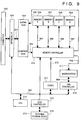
- Fig. 9 is a block diagram showing the detailed arrangement of the file apparatus 7.
- the file apparatus 7 is connected to the network 4 via a connector 500.
- a signal input via the connector 500 is input to a network interface circuit 503, and is then input to a compression/expansion circuit 504 via a signal line 551.
- An input signal 551 from the network is input to the compression/expansion circuit 504, and is converted from multi-value image information to compressed information. The converted information is then output to a memory controller 510.
- An output signal 552 from the compression/expansion circuit 504 is stored in one of a memory A 506, memory B 507, memory C 508, and memory D 509, or two cascade-connected memories under the control of the memory controller 510.
- the memory controller 510 of the file apparatus 7 has five control modes. One of these control modes is set by a CPU 516.
- the five control modes include a mode for exchanging data between the memories A 506 to D 509 and a CPU bus 560, a mode for exchanging data with a CODEC bus 570 of a CODEC 517, a mode for exchanging data between the memories A 506 to D 509 and a bus 562 of a magnification circuit 511 under the control of a DMA controller 518, a mode for storing a signal 511 from the network interface circuit 502 in one of the memories A 506 to D 509, and a mode for reading out the memory contents of one of the memories A 506 to D 509, and outputting the readout memory contents onto a signal line 556.
- Each of the memories A 506 to D 509 has a capacity of 2 Mbytes, and can store an image of A4 size or equivalent at a resolution of 400 dpi.
- a SCSI controller 519 attains an interface with an external storage device 573 connected to the file apparatus 7.
- the external storage device 573 comprises, e.g., a magnetooptical disk device, and stores data such as image information.
- the CODEC 517 reads out image information stored in one of the memories A 506 to D 509, encodes the readout information by a desired one of MH, MR, and MMR methods, and thereafter, re-stores the encoded information in one of the memories A 506 to D 509.
- the CODEC 517 reads out encoded information stored in one of the memories A 506 to D 509, decodes the readout information by a desired one of MH, MR, and MMR methods, and thereafter, re-stores the decoded information in one of the memories A 506 to D 509 as image information.
- the functions include:
- an image read by the reading device 10 is printed, an image stored in the file apparatus 7 is read out and printed, an image edited by the computer apparatus 8 is printed, or an image received by the facsimile device 6 is printed.
- an image to be transmitted is generated by the reading device 10, is read out from the file apparatus 7, or is edited by the computer apparatus 8, and such an image is transmitted by the facsimile device 6.
- image data is exchanged among the apparatuses via the network 4.
- Image data transfer via the network 4 should be attained in various data transfer modes depending on the natures of the apparatuses to be used.
- the following functions are available:
- Each of the apparatuses has a function of transmitting transfer data while dividing it into a plurality of blocks or simultaneously transmitting a plurality of pages of image data in correspondence with the communication state (data traffic amount) on the network 4.
- the communication state is defined by the busy rate of the communication line of the network 4.
- the transmission method of image data from a transfer source to a transfer destination is controlled in correspondence with the processing modes of image data in the apparatus as the transfer destination.
- the processing modes include, e.g., an immediate processing mode, time designation processing mode, non-time designation processing mode, simultaneous processing mode, and divisional processing mode.
- Whether or not the transfer source compresses image data is selected in correspondence with the compression method of the apparatus as the transfer destination.
- Fig. 10 shows the format of image data used in this system.
- control data as initial data designates by which apparatus and how image data is to be processed.
- This control data is transmitted as one frame prior to transmission of image data.
- the control data frame is followed by an image data frame.
- Image data for each page is divided by an EOP (end of page) code.
- the EOP code is added upon creation of image data.
- the end of an image file is delimited by an EOF code.
- the EOF code is similarly added upon creation of image data.
- image data can be transferred in units of 2 pages, 1 page, or half page (uniquely divided by 1 Mbyte).
- a network interface (network I/F) of the transmitting apparatus inserts an EOB (end of block) every 1 Mbytes in image data for one page.
- a mode in which one frame includes further segmented image data is defined in addition to the above-mentioned 1-page transfer mode, half-page transfer mode, and 2-page transfer mode. More specifically, one frame can include image data for one line.
- a network interface of the transmitting apparatus inserts an EOL (end of line) at the end of each line upon transmission.
- Fig. 10 exemplifies a correspondence between frames and data in the half-page transfer mode.
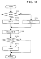
- Fig. 11 shows the control sequence for detecting a busy rate BR of signal lines of the network 4, which is executed every unit time by each apparatus of the network 4.
- each apparatus determines that the signal line is used by another apparatus, i.e., is busy. If the signal line is busy, the value of a counter BSY indicating a busy state is counted up in step S102; otherwise, the value of a counter IDL indicating an idle state is counted up in step S104.
- the busy rate BR is calculated by: When one of these counters overflows, the two counters are reset.
- Fig. 12 is a flow chart showing the image data transfer routine in each apparatus.
- step S150 the value BR, i.e., the busy rate of the network 4 is checked.
- step S152 If BR is small (0 ⁇ BR ⁇ 20), image data for two pages are transmitted to a destination apparatus in one frame in step S152. If one file includes 10 pages, the transfer operation of the file can be completed by transferring five frames. While the signal line is not too busy, even if long data is transferred, the influence (e.g., transmission of another apparatus is waited) on the entire system is small.
- BR has an intermediate value (20 ⁇ BR ⁇ 60)
- the mode for sending image data for one page in one frame to a destination apparatus is executed in step S154. If one file includes 10 pages, the transfer operation of the file can be completed by transferring 10 frames.
- step S156 the mode for sending image data for half a page in one frame to a destination apparatus is executed in step S156.
- the transfer operation of the file can be completed by transferring 20 frames.
- the half-page transfer mode since the data amount per frame is reduced, the busy rate of the system can be prevented from further increasing.
- a mode for sending data for one line in one frame may be executed.
- the reading device 10 sends a control data frame to the printer apparatus 5 first.
- the printer apparatus 5 receives the control data frame, analyzes control data, and detects that image data frames following the control data, and the image data is sent in units of one page, two pages, or half a page.
- Image data from the reader 1 is input to the controller 2 via the connector 115.
- Original information read by the reader 1 is input to the compression circuit 121 via the connector 120.
- the data is not compressed by the compression circuit 121 but is input to the memory 122.
- Image data from the memory 122 is input to the network interface circuit 123.
- the CPU 125 outputs image data in units of one page, two pages, or half a page in correspondence with the communication state (value BR) of the network 4 via the connector 125.
- the image data on the network 4 is printed by the printer apparatus 5.
- information read by the reader 1 can be printed by the printer apparatus 5.
- dividing modes of image data are not limited to the above-mentioned line, half-page, 1-page, and 2-page modes, and these modes are merely examples.
- facsimile transmission is performed from the reading device 10 via the facsimile device 6.
- the user when a user depresses the FAX switch 32 (Fig. 5), the user inputs data for designating a facsimile device to be used, telephone number data of a destination, transmission mode data (immediate or timer transmission mode), designated transmission time data, and the like, using the ten-key pad 33.
- the immediate transmission is called "direct communication" in a normal facsimile device, and in this mode, an image read by a reading sensor is sent to a transmitter in units of lines without being stored in a memory.
- direct communication in a normal facsimile device, and in this mode, an image read by a reading sensor is sent to a transmitter in units of lines without being stored in a memory.
- the reading device 10 transfers data input by the user to the facsimile device 6 together with a control data frame. Upon reception of these data, the facsimile device 6 can prepare for reception of image data which follows, i.e., reception in units of lines.
- the facsimile device 6 connects a telephone line to a destination.
- image data read by the reader 1 of the reading device 10 is input to the controller 2 via the connector 115.
- the controller 2 controls the compression circuit 121 to compress the read image data.
- the compressed image data i.e., encoded data for facsimile transmission, is input to the network interface circuit 123 without being stored in the memory 122.
- the CPU 125 (Fig. 4) of the reading device outputs encoded data for line onto the network 4 via the connector 124.
- image data is sent in units of lines for the following reason. More specifically, in the immediate transmission mode, image data is transmitted in units of lines since facsimile transmission performed by the facsimile device 6 and the image reading operation performed by the reading device 10 must be synchronized with each other in real time. That is, whether image is transmitted divisionally or simultaneously is controlled between the reading device 10 and the facsimile device 6 in correspondence with the communication state of the network.
- Compressed data on the network is input to the network interface circuit 409 via the connector 8 (Fig. 8) of the facsimile device 6.
- An output signal 453 from the network interface circuit 409 is stored in the memory B 406 under the control of the memory controller 404.
- the CPU 412 connects the memory B 406 of the memory controller 404 to the CPU bus 462.
- the CPU 412 sequentially reads out encoded data from the memory B 406, and transfers the readout data to the MODEM 414.
- the MODEM 414 modulates the encoded data, and transmits it onto the telephone line via the NCU.
- the reading device 10 is preferably released from the original reading device as soon as possible. To achieve this, the reading device 10 reads an image for one page (or one or more pages), and temporarily stores the read image in a memory. Thereafter, the stored image is compressed to facsimile codes, and the compressed data is temporarily stored in the memory 122 (Fig. 4). The reading device 10 sends the data stored in the memory 122 to the facsimile device 6.
- a facsimile transmission mode is called a non-time designation transmission mode. In the non-time designation transmission mode, image data to be transferred to the facsimile device 6 is divided in correspondence with the busy rate of the network 4.
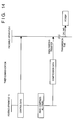
- Fig. 14 shows the timer transmission sequence.
- the difference between the timer transmission mode and the immediate transmission mode is that original images can be simultaneously read and all the image data can be simultaneously transferred to the facsimile device 6 since actual transmission is performed later. Control data is sent prior to transmission of image data in the same manner as in the immediate transmission mode.
- the reader 1 reads all original images in turn, and the read image data are compressed to facsimile codes by the compression circuit 121.
- the compressed data are stored in the memory 122.
- the compressed original data corresponding to the number of originals are stored in the memory 122.
- the CPU 125 outputs all the compressed data via the connector 124. In this case, the CPU 125 divides image data as needed in correspondence with the busy rate of the network 4 in accordance with the control sequences shown in Figs. 11 and 12.
- the compressed data on the network 4 is input to the network interface 409 via the connector 400.
- An output signal 453 from the network interface circuit 409 is stored in the memory A 405 under the control of the memory controller 404.
- the CPU 412 connects the memories A 405 and B 406 to the bus line 463 of the CODEC 411.
- the CODEC 411 reads out the compressed data from the memory A 405, encodes the data in correspondence with the encoding method of a destination of FAX transmission, and writes the encoded data in the memory B 406.
- the CPU 412 connects the memory B 406 of the memory controller 404 to the CPU bus 462.
- the CPU 412 sequentially reads out the encoded data from the memory B 406, and transfers the readout data to the MODEM 414.
- the MODEM 414 modulates the encoded data, and transmits it onto the telephone line via the NCU.
- both the reading device 10 and the filing apparatus 7 have the compression circuits (the compression/expansion circuit in the filing apparatus 7).
- the compression method in the filing apparatus 7 must be the one that is compatible with the filing apparatus 7 since image data is expanded by the filing apparatus 7.
- the reading device 10 directly transfers the image data to the filing apparatus 7 without compressing it since the compression method of the filing apparatus 7 has priority over that of the reading device 10.
- the reading device 10 compresses the read image data, and transfers the compressed image data to the filing apparatus.
- the filing apparatus 7 stores the compressed data in a storage medium.
- a user depresses a file switch 35 (Fig. 5). Then, the display 34 displays a message urging a user to designate a filing apparatus. Assume that the user designates the filing apparatus 7.
- Fig. 15 shows the data flow between the reading device 10 and the filing apparatus 7.
- the reading device 10 sends, to the filing apparatus, a message frame indicating that the filing apparatus 7 is designated.
- the filing apparatus 7 informs the compression method of its own compression circuit (504 in Fig. 9) to the reading device 10.
- the reading device 10 informs, to the filing apparatus 7, if the compression method is the same or different.
- the filing apparatus 7 can detect based on this information whether or not it needs to compress data sent from the reading device 10.
- the reading device 10 begins to read original images.
- Image data from the reader 1 is input to the controller 2 via the connector 115.
- the controller 2 determines depending on the matching state of the compression methods of the two apparatuses whether the image data is input to the compression circuit 121 via the connector 120 or is stored in the memory 122 in the form of raster data.
- the image data is compressed by the compression circuit 121 in the controller.
- the compressed image data is stored in the memory 122 in correspondence with the number of originals.
- the reading device 10 adopts a different compression method from that of the filing apparatus 7 the image data is stored in the memory 122 in the form of raster data in correspondence with the number of originals.
- the CPU 125 outputs all the compressed data (when the two apparatuses have the same method) or raster data (when the two apparatuses have different methods) onto the network via the connector 124 together with file name data.
- transmission data may be divided in correspondence with the busy state of the network 4.
- the compressed or raster data on the network 4 are input to the network interface circuit 503 via the connector 500.
- the network interface circuit 503 inputs the received raster data to the compression/expansion circuit 504 in accordance with an instruction from the CPU 516.
- the raster data are individually converted into compressed data 552.
- the compressed data 552 are input to the memory controller 510.
- the memory controller 510 stores the compressed data 552 in the memory A 506.
- the CPU 516 connects the memories A 506 and B 507 of the memory controller 510 to the bus line 570 of the CODEC 517.
- the CODEC 517 reads out the compressed data from the memory A 506, encodes the readout data by the MR method, and writes the encoded data in the memory B 507.
- the CPU 516 Upon completion of encoding by the CODEC 517, the CPU 516 connects the memory B 507 of the memory controller 510 to the CPU bus 560. The CPU 516 sequentially reads out the encoded data from the memory B 507, and transfers the readout data to the SCSI controller 519. The SCSI controller 519 stores encoded data 572 in the external storage device 573.
- the filing apparatus 7 can omit the compression processing, the filing apparatus 7 can share its performance with another processing, i.e., expansion processing of another image data requested by the computer apparatus 8.
- the CPU 516 instructs the interface 503 and the memory controller 510 to store the received data in the memory A 506 via the line 552.
- the CPU 516 connects the memories A 506 and B 507 of the memory controller 510 to the bus line 570 of the CODEC 517.
- the CODEC 517 reads out compressed data from the memory A 506, encodes the compressed data by the MR method, and writes the encoded data in the memory B 507.
- the CPU 516 connects the memory B 507 of the memory controller 510 to the CPU bus 560.
- the CPU 516 sequentially reads out the encoded data from the memory B 507, and transfers the readout data to the SCSI controller 519.
- the SCSI controller 519 stores encoded data 572 in the external storage device 573.
- the filing operation of data from the reading device 10 to the filing apparatus 7 has been exemplified.
- the output apparatus is not limited to the filing apparatus. Whether or not the compression methods of input and output apparatuses are the same is taken into account, and when the same compression method is adopted, the input apparatus performs compression to reduce the load on the output device; when different methods are adopted, the output apparatus performs compression to assure data compatibility.
Abstract
Description
- The present invention relates to an information processing system including at least an input apparatus and a processing apparatus, an information processing apparatus used in the system, and a data transfer control method in a network.
- In a network technique that has been proposed recently, a plurality of apparatuses, especially, a scanner apparatus, a printer apparatus, a facsimile device, and a management apparatus for managing these apparatuses, are connected to a network, and the entire network operates as one system.
- Conventionally, when an image is read using the scanner connected to the network, and the read image data is transmitted to another apparatus on the network, the entire image data input in a single scanner input operation is normally transferred as one unit.
- For this reason, even when only an image of a portion of an original is required, the entire page of the original must be transmitted. On the contrary, when images on a plurality of pages of an original are successively input, image data for the plurality of pages must be divisionally transmitted since they exceed one unit.
- For this reason, the conventional network system has poor data transfer efficiency when a read image is transmitted to another processing apparatus on the network.
- It is, therefore, an object of the present invention to provide an information processing system and an information processing apparatus, which can control communications in correspondence with the communication state in a network.
- In order to achieve the above object, according to the present invention, there is provided an information processing system having an input apparatus capable of inputting image data and transmitting the input image data, a processing apparatus capable of processing a received image, and a network to which the input and processing apparatuses are connected, the system realizing a function for inputting and processing image data as a whole, comprising:
control means for controlling to transmit image data input by the input apparatus divisionally or simultaneously in correspondence with a communication state in the network. - In order to achieve the above object, there is also provided an information processing apparatus connected to a network, for exchanging image data with the network, comprising:
means for inputting image data;
means for detecting a communication state in the network; and
control means for controlling to transmit image data input by the input means divisionally or simultaneously onto the network in correspondence with the detected communication state. - According to a preferred aspect of the present invention, the control means controls transmission in correspondence with a data traffic in the network.
- According to another preferred aspect of the present invention, the control means is included in the input apparatus.
- According to still another preferred aspect of the present invention, the input apparatus comprises an image input/output apparatus for reading an image, and outputting the read image.
- According to still another preferred aspect of the present invention, when the input apparatus comprises a reading device which reads an original, the control means detects a communication state, and controls the input apparatus to transmit a portion or the entire page of a read original image in correspondence with the detected communication state.
- According to still another preferred aspect of the present invention, the input apparatus comprises a reading device which reads an original, the control means detects a communication state, and controls the input apparatus to transmit read image data of originals in units of unitary page or in units of a plurality of pages.
- It is another object of the present invention to provide an information processing system and an information processing apparatus, which can control communications in correspondence with the processing mode on the processing apparatus side.
- In order to achieve the above object, according to the present invention, there is provided an information processing system having an input apparatus capable of inputting image data and transmitting the input image data, a processing apparatus capable of processing a received image, and a network to which the input and processing apparatuses are connected, the system realizing a function for inputting and processing image data as a whole, comprising:
control means for setting a different transmission sequence of image data from the input apparatus to the processing apparatus in correspondence with a processing manner of image data on the processing apparatus side. - In order to achieve the above object, there is also provided an information processing apparatus, which is connected to a network, and exchanges image data with the network, comprising:
means for inputting image data; and
control means for transmitting designation information for designating a processing manner in a processing apparatus which processes input image data to the processing apparatus, and controlling to divisionally or simultaneously transmit image data input by the input means in correspondence with a processing manner. - According to a preferred aspect of the present invention, the control means determines the processing manner of image data on the processing apparatus side in the input apparatus, and informs the determination result to the processing apparatus side.
- According to another preferred aspect of the present invention, the control means is arranged in the input apparatus.
- According to still another preferred aspect of the present invention, the processing manner of image data on the processing apparatus side is defined such that an image input operation in the input apparatus and processing of image data in the processing apparatus are substantially simultaneously performed.
- According to still another preferred aspect of the present invention, the processing manner of image data on the processing apparatus side is defined such that processing of image data in the processing apparatus is started after an image input operation in the input apparatus is completed.
- According to still another preferred aspect of the present invention, the processing manner of image data on the processing apparatus side is defined such that processing of image data in the processing apparatus is started at a time different from an input time of an image in the input apparatus.
- According to still another preferred aspect of the present invention, the input apparatus comprises an image reading device, and the processing apparatus comprises a facsimile device.
- According to still another preferred aspect of the present invention, when the input apparatus comprises an image reading device, and the processing apparatus comprises a facsimile device,
the processing manner is an immediate transmission mode, and the control means transfers image data to the processing apparatus in units of lines. - According to still another preferred aspect of the present invention, when the input apparatus comprises an image reading device, and the processing apparatus comprises a facsimile device,
the processing manner is a timer transmission mode, and the control means simultaneously transfers image data stored in a buffer and transmission time data to the processing apparatus. - According to still another preferred aspect of the present invention, when the input apparatus comprises an image reading device, and the processing apparatus comprises a facsimile device,
the processing manner is a buffer transmission mode, and the control means simultaneously transfers image data stored in a buffer to the processing apparatus. - It is still another object of the present invention to provide an information processing system and an information processing apparatus which can control communications depending on whether the format of information in an input apparatus is the same as or different from that on the processing apparatus side.
- In order to achieve the above object, according to the present invention, there is provided an information processing system, which comprises an input apparatus capable of inputting image data and transmitting the input image data, a processing apparatus capable of processing a received image, and a network to which the input and processing apparatuses are connected, the system realizing a function for inputting and processing image data as a whole, comprising:
control means for controlling a format of image data to be output from the input apparatus to the processing apparatus on the basis of a matching state between characteristics of image data processed by the input apparatus and characteristics of image data processed by the processing apparatus. - In order to achieve the above object, there is also provided an information processing apparatus, which is connected to a network, and exchanges image data with the network, comprising:
means for inputting image data;
means for acquiring processing characteristics of image data in a processing apparatus for processing the image data from an external apparatus; and
control means for controlling to divisionally or simultaneously transmit image data input by the input means in correspondence with a matching state between characteristics of image data of the input means, and the processing characteristics of image data in the processing apparatus. - According to a preferred aspect of the present invention, the matching state of the characteristics of image data is a matching state between compression methods of the input apparatus and the processing apparatus.
- According to another preferred aspect of the present invention, the input apparatus comprises first compression means, the processing apparatus comprises second compression means, and the control means disables the first compression means when a compression method of the first compression means is different from a compression method of the second compression means.
- According to still another preferred aspect of the present invention, the input apparatus comprises first compression means, the processing apparatus comprises second compression means, and the control means enables the first compression means when a compression method of the first compression means is the same as a compression method of the second compression means.
- According to still another preferred aspect of the present invention, the processing apparatus comprises a computer, a facsimile communication modem, a printer, a file, and the like.
- It is still another object of the present invention to provide an information processing system and an information processing apparatus, which can exchange information in a format most suitable for an information processing apparatus constituting a network.
- In order to achieve the above object, according to the present invention, there is provided an information processing system, which comprises an input apparatus capable of inputting image data and transmitting the input image data, a processing apparatus capable of processing a received image, and a network to which the input and processing apparatuses are connected, the system realizing a function for inputting and processing image data as a whole, comprising:
control means for controlling to divisionally or simultaneously transmit data input by the input apparatus in correspondence with a relationship between the input apparatus and the processing apparatus in the network. - It is still another object of the present invention to provide a data transfer control method which can improve the efficiency of a network by controlling the data amount which is a transfer unit in correspondence with the degree of data traffic in the network.
- In order to achieve the above object, according to the present invention, there is provided a data transfer control method between communication apparatuses in a network including a plurality of communication apparatuses, comprising the steps of:
detecting a busy rate of the network; and
increasing/decreasing an amount of data which is a transfer unit in correspondence with the detected busy rate. - It is still another object of the present invention to provide a data transfer control method which can improve the efficiency of a network by controlling the data amount which is a transfer unit in correspondence with any time difference when the data input timing and the data processing timing are different between apparatuses in the network.
- In order to achieve the above object, according to the present invention, there is provided a data transfer control method from a data input apparatus to a data processing apparatus in a network including the data input apparatus and the data processing apparatus, comprising the steps of:
detecting a time difference between an input time of data in the data input apparatus and a processing time of the data in the processing apparatus; and
increasing/decreasing an amount of data which is a transfer unit in correspondence with the detected time difference. - It is still another object of the present invention to provide a data transfer control method which can distribute functions and processing loads of an input apparatus and a processing apparatus when both the input and processing apparatuses in a network have pre-processing functions.
- In order to achieve the above object, there is provided a data control method from a data input apparatus to a data processing apparatus in a network including the data input apparatus having a first pre-processing function and the data processing apparatus having a second pre-processing function equivalent to the first pre-processing function, comprising the steps of:
discriminating a matching state between the first and second pre-processing functions, and informing a discrimination result to the data processing apparatus; and
executing pre-processing in the input apparatus and transferring pre-processed data to the processing apparatus when the first and second pre-processing functions are the same, and transferring data before pre-processing to the processing apparatus when the first and second pre-processing functions are different from each other; and
determining in accordance with the information in the processing apparatus whether or not the second pre-processing function is executed for the data sent from the data input apparatus. - Other features and advantages of the present invention will be apparent from the following description taken in conjunction with the accompanying drawings, in which like reference characters designate the same or similar parts throughout the figures thereof.
-
- Fig. 1 is a block diagram showing the entire information processing system according to an embodiment of the present invention;
- Fig. 2 is a sectional view showing the arrangement of a
reader 1 in areading device 10; - Fig. 3 is a block diagram showing an image processing unit in the
reader 1 in thereading device 10; - Fig. 4 is a block diagram of a
controller 2 and anoperation unit 3 in thereading device 10; - Fig. 5 is a view showing the panel layout of the
operation unit 3; - Fig. 6 is a view for explaining the scheme for designating respective apparatuses in the system;
- Fig. 7 is a schematic view showing the arrangement of a
printer apparatus 5; - Fig. 8 is a block diagram showing a
facsimile device 6; - Fig. 9 is a block diagram showing a file apparatus 7;
- Fig. 10 is a view showing the dividing format of frames on the network;
- Fig. 11 is a flow chart showing the control sequence for detecting a busy state on the network;
- Fig. 12 is a flow chart showing the control sequence for selecting different communication procedures in correspondence with the busy state;
- Fig. 13 is a chart showing the data transfer sequence in an immediate transmission mode;
- Fig. 14 is a chart showing the data transfer sequence in a timer transmission mode; and
- Fig. 15 is a chart showing the data transfer sequence in a file operation of image data.
- The preferred embodiments of the present invention will be described below with reference to the accompanying drawings.
- Fig. 1 is a block diagram showing the arrangement of an information processing system according to an embodiment of the present invention.
- Referring to Fig. 1, this system constitutes a LAN (local area network) connected to a communication line (network) 4. An
image reading device 10 for reading an image, aprinter apparatus 5 for printing an image on a paper sheet, afacsimile device 6 for transmitting or receiving an image via a telephone line, a file apparatus 7 for storing an image or reading out the stored image, and acomputer apparatus 8 for receiving an image and editing the received image are connected to thecommunication line 4. These apparatuses are respectively assigned with identifiers indicating the types of apparatuses, and address numbers on the network. - In this system which is characterized in that an image is transmitted, and the transmitted image is received, the
image reading device 10 is classified as an image input apparatus, theprinter apparatus 5 is classified as an image output apparatus, and thefacsimile device 6, the file apparatus 7, and thecomputer apparatus 8 are classified as image input/output apparatuses. From the viewpoint of a function capable of inputting an image, theimage reading device 10, thefacsimile device 6, thefile apparatus 6, and thecomputer apparatus 8 are also image input apparatuses. - The system arrangement shown in Fig. 1 will be described in more detail below.
-
- The image reading device has a
reader 1 for reading an original image, and converting the read image into image data, acontroller 2 for controlling image data from thereader 1, and anoperation unit 3 which is connected to thecontroller 2 and used to designate an output method of image data from thereader 1. - Fig. 2 is a sectional view showing the arrangement of the
reader 1. - Originals stacked on an
original feeder 101 are fed onto an originaltable glass surface 102 one by one. When an original is fed, alamp 103 of a scanner is turned on, and ascanner unit 104 moves to irradiate light onto the original. Light reflected by the original is transmitted through alens 108 viamirrors - Fig. 3 is a block diagram showing the signal processing arrangement of the
reader 1. - Image information input to the
CCD 109 is photoelectrically converted into electrical signals. Color information signals from theCCD 109 are amplified byamplifiers D converter 111. Output signals from the A/D converter 111 are input to ashading circuit 112, and are subjected to correction of illumination nonuniformity of thelamp 103 and of sensitivity nonuniformity of theCCD 109. Output signals from theshading circuit 112 are input to amagnification circuit 113. Themagnification circuit 113 attains magnification in the main scanning direction. Maginification in the sub-scanning direction is attained by changing the scanning speed of thescanner unit 104. Anedge emphasis circuit 114 attains edge emphasis by emphasizing high-frequency components of signals from themagnification circuit 113. Output signals from theedge emphasis circuit 114 are output to thecontroller 2 via aconnector 115. - Fig. 4 is a block diagram showing the
controller 2 and theoperation unit 3. - Referring to Fig. 4, a
connector 120 includes a terminal for receiving image data from thereader 1. Signals input via theconnector 120 are input to acompression circuit 121. An output signal from thecompression circuit 121 is input to amemory 122. A signal output from thememory 122 is output onto thenetwork 4 via anetwork interface 123 and aconnector 124. ACPU 125 controls theoverall controller 2 and receives information input from theoperation unit 3. - Fig. 5 shows the layout of buttons on the panel of the
operation unit 3. On the panel, aprinter switch 31 for designating an output destination of an image read by thereader 1 to theprinter apparatus 5, aFAX switch 32 for designating an output destination of an image read by thereader 1 to thefacsimile device 6, a ten-key pad 33, and the like are arranged. - In this system, all the apparatuses connected to the network have a table representing the network configuration, as shown in Fig. 6. This table is configured in the order of addresses assigned to the apparatuses on the
network 4, and stores an identification name of an apparatus assigned to the corresponding address value, the type of the apparatus (such as a facsimile device, a printer apparatus, and the like), and the attribute of the apparatus in units of apparatuses. - A user of this system can designate an apparatus, from which image data read by the
image reading device 10 is to be output, by depressing theswitch printer switch 31. When only one printer is connected to the system, theprinter apparatus 5 is designated to be the output destination by only depressing theprinter switch 31. If a plurality of apparatuses having printer attributes are connected to thenetwork 4, a message, which indicates that a plurality of printers are connected and urges a user to select one of printers, is displayed on adisplay 34. - On the other hand, when the user depresses the
FAX switch 32 to facsimile-transmit image data read by theimage reading device 10, a message urging a user to input the telephone number of a transmission destination appears on thedisplay 34. The user inputs the telephone number of the transmission destination using the ten-key pad 33. Then, thedisplay 34 displays a message urging a user to designate a facsimile transmission mode. The transmission mode includes an immediate transmission mode for immediately performing transmission, a timer transmission mode for performing facsimile transmission at a designated time, and the like, and serial numbers are assigned to these transmission modes. The user designates a desired transmission mode by inputting a number using the ten-key pad. When the timer transmission mode is designated, thedisplay 34 further displays a message urging a user to input a transmission designation time. The user inputs the transmission time using the ten-key pad 33. -
- The arrangement and operation of the
printer apparatus 5 will be described below with reference to Fig. 7. - Referring to Fig. 7, a signal input to the
printer apparatus 5 is converted into an optical signal by anexposure controller 201, and the optical signal is irradiated onto aphotosensitive body 202 in accordance with an image signal. A latent image formed on thephotosensitive body 202 by the irradiated light is developed by adeveloper 203. A transfer sheet is fed from a transfersheet stacking unit photosensitive body 202 onto the transfer sheet in atransfer unit 206. The transferred image is fixed on the transfer sheet in afixing unit 207, and the transfer sheet is exhausted outside the apparatus via anexhaust unit 208. When a sort function of asorter 220 is enabled, the transfer sheet output via theexhaust unit 208 is exhausted onto a corresponding one of bins of thesorter 220; when the sort function is disabled, the transfer sheet is exhausted onto the uppermost bin of thesorter 220. - A method of outputting two images on two surfaces of a single output sheet will be explained below. After an output sheet subjected to fixing in the fixing
unit 207 is temporarily fed to theexhaust unit 208, the feed direction of the sheet is reversed, and the output sheet is then fed to a stackingunit 210 via a feeddirection switching member 209. In the stackingunit 210, the sheet on one surface of which an image is printed waits for a re-feed operation for printing an image on the other surface of the sheet. When the next original to be read is ready, an original image is read in the same manner as in the above-mentioned process. In this case, since the output sheet is fed from the re-feed stackingunit 210, two original images can be output onto two surfaces of a single output sheet. - Fig. 8 is a block diagram showing the detailed arrangement of the
facsimile device 6. - The
facsimile device 6 is connected to thenetwork 4 via aconnector 400. A signal input via theconnector 400 is input to anetwork interface circuit 409, and is then input to amemory controller 404 via asignal line 453. - This facsimile device has four memory banks (a
memory A 405, amemory B 406, amemory C 407, and a memory D 408). Each of the memories A 405,B 406,C 407, andD 408 has a capacity of 2 Mbytes, and can store an image of A4 size or equivalent at a resolution of 400 dpi. - When image data from the
image reading device 10 is to be stored in one of the memories A 405 toD 408, asignal 453 from thenetwork interface circuit 409 is input to thememory controller 404, and the image data is stored in one of the memories A 405 toD 408 or in two cascade-connected memories under the control of the memory controller. - The
memory controller 404 has four control modes for data transfer to the memories, and aCPU 412 sets thecontroller 404 in one of the four modes. The four control modes include a mode for exchanging data between the memories A 405 toD 408 and aCPU bus 462, a mode for exchanging data with aCODEC bus 463 of a CODEC 411 (with an encoding/decoding function), a mode for exchanging the contents of the memories A 405 toD 408 with abus 454 from amagnification circuit 403 under the control of aDMA controller 402, a mode for storingimage data 453 from thenetwork interface circuit 409 in one of the memories A 405 toD 408, and a mode for reading out the memory contents of one of the memories A 405 toD 408, and outputting the readout contents onto asignal line 452. - A
SCSI controller 413 performs interface control with ahard disk 420 connected to thefacsimile device 6 via aSCSI bus 421. Thehard disk 420 accumulates image data in a facsimile transmission mode or a facsimile reception mode. - The
CODEC 411 reads out image information stored in one of the memories A 405 toD 408, encodes the readout information by a desired one of MH, MR, and MMR methods, and thereafter, re-stores the encoded information in one of the memories A 405 toD 408. On the other hand, theCODEC 411 reads out encoded information stored in one of the memories A 405 toD 408, decodes the readout information by a desired one of MH, MR, and MMR methods, and thereafter, re-stores the decoded information in one of the memories A 405 toD 408 as image information. - A MODEM 414 has a function of modulating encoded information from the
CODEC 411 or the hard disk connected to theSCSI controller 413 to transmit it onto a telephone line, and a function of demodulating information sent from anNCU 415. The demodulated encoded information is transferred to theCODEC 411 or thehard disk 420 connected to theSCSI controller 413 as encoded information. TheNCU 415 is directly connected to the telephone line, and exchanges information with an exchange equipped in a telephone office in a predetermined protocol. - Fig. 9 is a block diagram showing the detailed arrangement of the file apparatus 7.
- The file apparatus 7 is connected to the
network 4 via aconnector 500. A signal input via theconnector 500 is input to anetwork interface circuit 503, and is then input to a compression/expansion circuit 504 via asignal line 551. An input signal 551 from the network is input to the compression/expansion circuit 504, and is converted from multi-value image information to compressed information. The converted information is then output to amemory controller 510. - An
output signal 552 from the compression/expansion circuit 504 is stored in one of amemory A 506,memory B 507,memory C 508, andmemory D 509, or two cascade-connected memories under the control of thememory controller 510. - The
memory controller 510 of the file apparatus 7 has five control modes. One of these control modes is set by aCPU 516. The five control modes include a mode for exchanging data between the memories A 506 toD 509 and aCPU bus 560, a mode for exchanging data with aCODEC bus 570 of aCODEC 517, a mode for exchanging data between the memories A 506 toD 509 and abus 562 of amagnification circuit 511 under the control of aDMA controller 518, a mode for storing asignal 511 from the network interface circuit 502 in one of the memories A 506 toD 509, and a mode for reading out the memory contents of one of the memories A 506 toD 509, and outputting the readout memory contents onto asignal line 556. - Each of the memories A 506 to
D 509 has a capacity of 2 Mbytes, and can store an image of A4 size or equivalent at a resolution of 400 dpi. - A
SCSI controller 519 attains an interface with anexternal storage device 573 connected to the file apparatus 7. Theexternal storage device 573 comprises, e.g., a magnetooptical disk device, and stores data such as image information. - The
CODEC 517 reads out image information stored in one of the memories A 506 toD 509, encodes the readout information by a desired one of MH, MR, and MMR methods, and thereafter, re-stores the encoded information in one of the memories A 506 toD 509. On the other hand, theCODEC 517 reads out encoded information stored in one of the memories A 506 toD 509, decodes the readout information by a desired one of MH, MR, and MMR methods, and thereafter, re-stores the decoded information in one of the memories A 506 toD 509 as image information. - In this system, many functions are defined as those for attaining one function using a plurality of apparatuses. For example, the functions include:
- i: Print Function
- ii: Facsimile Function
- iii: Image Filing Function
- When an image is printed on a paper sheet by the
printer apparatus 5, an image read by thereading device 10 is printed, an image stored in the file apparatus 7 is read out and printed, an image edited by thecomputer apparatus 8 is printed, or an image received by thefacsimile device 6 is printed. - When an image is facsimile-transmitted to a distant station, an image to be transmitted is generated by the
reading device 10, is read out from the file apparatus 7, or is edited by thecomputer apparatus 8, and such an image is transmitted by thefacsimile device 6. - In this system, image data is exchanged among the apparatuses via the
network 4. Image data transfer via thenetwork 4 should be attained in various data transfer modes depending on the natures of the apparatuses to be used. For this purpose, in this system, the following functions are available: - : Each of the apparatuses has a function of transmitting transfer data while dividing it into a plurality of blocks or simultaneously transmitting a plurality of pages of image data in correspondence with the communication state (data traffic amount) on the
network 4. In this embodiment, the communication state is defined by the busy rate of the communication line of thenetwork 4. - : The transmission method of image data from a transfer source to a transfer destination is controlled in correspondence with the processing modes of image data in the apparatus as the transfer destination. In this embodiment, the processing modes include, e.g., an immediate processing mode, time designation processing mode, non-time designation processing mode, simultaneous processing mode, and divisional processing mode.
- : Whether or not the transfer source compresses image data is selected in correspondence with the compression method of the apparatus as the transfer destination.
- In this network system, image data is transferred in units of frames. Fig. 10 shows the format of image data used in this system.
- Referring to Fig. 10, control data as initial data designates by which apparatus and how image data is to be processed. This control data is transmitted as one frame prior to transmission of image data. The control data frame is followed by an image data frame.
- Image data for each page is divided by an EOP (end of page) code. The EOP code is added upon creation of image data. The end of an image file is delimited by an EOF code. The EOF code is similarly added upon creation of image data.
- In this network system, image data can be transferred in units of 2 pages, 1 page, or half page (uniquely divided by 1 Mbyte).
- In a half-page transfer mode, a network interface (network I/F) of the transmitting apparatus inserts an EOB (end of block) every 1 Mbytes in image data for one page.
- In this network, a mode in which one frame includes further segmented image data is defined in addition to the above-mentioned 1-page transfer mode, half-page transfer mode, and 2-page transfer mode. More specifically, one frame can include image data for one line. In this mode, a network interface of the transmitting apparatus inserts an EOL (end of line) at the end of each line upon transmission.
- Fig. 10 exemplifies a correspondence between frames and data in the half-page transfer mode.
- Fig. 11 shows the control sequence for detecting a busy rate BR of signal lines of the
network 4, which is executed every unit time by each apparatus of thenetwork 4. When a carrier signal is output onto a signal line, each apparatus determines that the signal line is used by another apparatus, i.e., is busy. If the signal line is busy, the value of a counter BSY indicating a busy state is counted up in step S102; otherwise, the value of a counter IDL indicating an idle state is counted up in step S104. In step S106, the busy rate BR is calculated by:
When one of these counters overflows, the two counters are reset. - Fig. 12 is a flow chart showing the image data transfer routine in each apparatus. In step S150, the value BR, i.e., the busy rate of the
network 4 is checked. - If BR is small (0 < BR ≦ 20), image data for two pages are transmitted to a destination apparatus in one frame in step S152. If one file includes 10 pages, the transfer operation of the file can be completed by transferring five frames. While the signal line is not too busy, even if long data is transferred, the influence (e.g., transmission of another apparatus is waited) on the entire system is small.
- If BR has an intermediate value (20 < BR ≦ 60), the mode for sending image data for one page in one frame to a destination apparatus is executed in step S154. If one file includes 10 pages, the transfer operation of the file can be completed by transferring 10 frames.
- If BR is large (BR > 60), the mode for sending image data for half a page in one frame to a destination apparatus is executed in step S156. In this mode, if one file includes 10 pages, the transfer operation of the file can be completed by transferring 20 frames. With the half-page transfer mode, since the data amount per frame is reduced, the busy rate of the system can be prevented from further increasing.
- Of course, when the busy rate is extremely high (e.g., BR > 80), a mode for sending data for one line in one frame may be executed.
- A case will be exemplified below wherein data is output from the
reading device 10 to theprinter apparatus 5. - The
reading device 10 sends a control data frame to theprinter apparatus 5 first. Theprinter apparatus 5 receives the control data frame, analyzes control data, and detects that image data frames following the control data, and the image data is sent in units of one page, two pages, or half a page. - Image data from the
reader 1 is input to thecontroller 2 via theconnector 115. Original information read by thereader 1 is input to thecompression circuit 121 via theconnector 120. When image data is to be output by the printer, the data is not compressed by thecompression circuit 121 but is input to thememory 122. Image data from thememory 122 is input to thenetwork interface circuit 123. - The
CPU 125 outputs image data in units of one page, two pages, or half a page in correspondence with the communication state (value BR) of thenetwork 4 via theconnector 125. The image data on thenetwork 4 is printed by theprinter apparatus 5. - With the above-mentioned processing, information read by the
reader 1 can be printed by theprinter apparatus 5. - Note that the dividing modes of image data are not limited to the above-mentioned line, half-page, 1-page, and 2-page modes, and these modes are merely examples.
- A case will be exemplified below wherein facsimile transmission is performed from the
reading device 10 via thefacsimile device 6. As described above, when a user depresses the FAX switch 32 (Fig. 5), the user inputs data for designating a facsimile device to be used, telephone number data of a destination, transmission mode data (immediate or timer transmission mode), designated transmission time data, and the like, using the ten-key pad 33. - The immediate transmission is called "direct communication" in a normal facsimile device, and in this mode, an image read by a reading sensor is sent to a transmitter in units of lines without being stored in a memory. A case will be described below with reference to Fig. 13 and the like wherein the immediate transmission mode is designated by the user.
- The
reading device 10 transfers data input by the user to thefacsimile device 6 together with a control data frame. Upon reception of these data, thefacsimile device 6 can prepare for reception of image data which follows, i.e., reception in units of lines. - The
facsimile device 6 connects a telephone line to a destination. - In the immediate transmission mode, as shown in Fig. 13, each time the
reading device 10 reads an original image for one line, it sends the image data to thefacsimile device 6, and thefacsimile device 6 sends the read image data to the destination via the telephone line. - More specifically, image data read by the
reader 1 of thereading device 10 is input to thecontroller 2 via theconnector 115. Thecontroller 2 controls thecompression circuit 121 to compress the read image data. The compressed image data, i.e., encoded data for facsimile transmission, is input to thenetwork interface circuit 123 without being stored in thememory 122. The CPU 125 (Fig. 4) of the reading device outputs encoded data for line onto thenetwork 4 via theconnector 124. - In the immediate transmission mode, image data is sent in units of lines for the following reason. More specifically, in the immediate transmission mode, image data is transmitted in units of lines since facsimile transmission performed by the
facsimile device 6 and the image reading operation performed by thereading device 10 must be synchronized with each other in real time. That is, whether image is transmitted divisionally or simultaneously is controlled between the readingdevice 10 and thefacsimile device 6 in correspondence with the communication state of the network. - Compressed data on the network is input to the
network interface circuit 409 via the connector 8 (Fig. 8) of thefacsimile device 6. Anoutput signal 453 from thenetwork interface circuit 409 is stored in thememory B 406 under the control of thememory controller 404. TheCPU 412 connects thememory B 406 of thememory controller 404 to theCPU bus 462. TheCPU 412 sequentially reads out encoded data from thememory B 406, and transfers the readout data to the MODEM 414. The MODEM 414 modulates the encoded data, and transmits it onto the telephone line via the NCU. - In facsimile communications, the
reading device 10 is preferably released from the original reading device as soon as possible. To achieve this, thereading device 10 reads an image for one page (or one or more pages), and temporarily stores the read image in a memory. Thereafter, the stored image is compressed to facsimile codes, and the compressed data is temporarily stored in the memory 122 (Fig. 4). Thereading device 10 sends the data stored in thememory 122 to thefacsimile device 6. Such a facsimile transmission mode is called a non-time designation transmission mode. In the non-time designation transmission mode, image data to be transferred to thefacsimile device 6 is divided in correspondence with the busy rate of thenetwork 4. - The timer transmission mode in facsimile transmission will be exemplified below. Fig. 14 shows the timer transmission sequence. The difference between the timer transmission mode and the immediate transmission mode is that original images can be simultaneously read and all the image data can be simultaneously transferred to the
facsimile device 6 since actual transmission is performed later. Control data is sent prior to transmission of image data in the same manner as in the immediate transmission mode. - The
reader 1 reads all original images in turn, and the read image data are compressed to facsimile codes by thecompression circuit 121. The compressed data are stored in thememory 122. In this case, the compressed original data corresponding to the number of originals are stored in thememory 122. - The
CPU 125 outputs all the compressed data via theconnector 124. In this case, theCPU 125 divides image data as needed in correspondence with the busy rate of thenetwork 4 in accordance with the control sequences shown in Figs. 11 and 12. - The compressed data on the
network 4 is input to thenetwork interface 409 via theconnector 400. Anoutput signal 453 from thenetwork interface circuit 409 is stored in thememory A 405 under the control of thememory controller 404. TheCPU 412 connects the memories A 405 andB 406 to thebus line 463 of theCODEC 411. TheCODEC 411 reads out the compressed data from thememory A 405, encodes the data in correspondence with the encoding method of a destination of FAX transmission, and writes the encoded data in thememory B 406. - When the transmission time has reached, the
CPU 412 connects thememory B 406 of thememory controller 404 to theCPU bus 462. TheCPU 412 sequentially reads out the encoded data from thememory B 406, and transfers the readout data to the MODEM 414. The MODEM 414 modulates the encoded data, and transmits it onto the telephone line via the NCU. -
- As shown in Figs. 8 and 9, in this system, both the
reading device 10 and the filing apparatus 7 have the compression circuits (the compression/expansion circuit in the filing apparatus 7). In order to file image data, the compression method in the filing apparatus 7 must be the one that is compatible with the filing apparatus 7 since image data is expanded by the filing apparatus 7. Thus, when image data read by thereading device 10 is stored in the filing apparatus 7, and these two apparatuses have different compression methods, thereading device 10 directly transfers the image data to the filing apparatus 7 without compressing it since the compression method of the filing apparatus 7 has priority over that of thereading device 10. On the other hand, when the two apparatuses have the same compression method, thereading device 10 compresses the read image data, and transfers the compressed image data to the filing apparatus. The filing apparatus 7 stores the compressed data in a storage medium. - In order to file images, a user depresses a file switch 35 (Fig. 5). Then, the
display 34 displays a message urging a user to designate a filing apparatus. Assume that the user designates the filing apparatus 7. - Fig. 15 shows the data flow between the reading
device 10 and the filing apparatus 7. Thereading device 10 sends, to the filing apparatus, a message frame indicating that the filing apparatus 7 is designated. The filing apparatus 7 informs the compression method of its own compression circuit (504 in Fig. 9) to thereading device 10. Thereading device 10 informs, to the filing apparatus 7, if the compression method is the same or different. The filing apparatus 7 can detect based on this information whether or not it needs to compress data sent from thereading device 10. - In this manner, preparation for image data transfer is established between the reading
device 10 and the filing apparatus 7. Thereading device 10 begins to read original images. - Image data from the
reader 1 is input to thecontroller 2 via theconnector 115. Thecontroller 2 determines depending on the matching state of the compression methods of the two apparatuses whether the image data is input to thecompression circuit 121 via theconnector 120 or is stored in thememory 122 in the form of raster data. When thereading device 10 adopts the same compression method as that of the filing apparatus 7, the image data is compressed by thecompression circuit 121 in the controller. The compressed image data is stored in thememory 122 in correspondence with the number of originals. When thereading device 10 adopts a different compression method from that of the filing apparatus 7, the image data is stored in thememory 122 in the form of raster data in correspondence with the number of originals. - The
CPU 125 outputs all the compressed data (when the two apparatuses have the same method) or raster data (when the two apparatuses have different methods) onto the network via theconnector 124 together with file name data. - As described above, transmission data may be divided in correspondence with the busy state of the
network 4. - In the filing apparatus 7, the compressed or raster data on the
network 4 are input to thenetwork interface circuit 503 via theconnector 500. - When the two apparatuses have the same method, the
network interface circuit 503 inputs the received raster data to the compression/expansion circuit 504 in accordance with an instruction from theCPU 516. The raster data are individually converted into compresseddata 552. Thecompressed data 552 are input to thememory controller 510. Thememory controller 510 stores thecompressed data 552 in thememory A 506. TheCPU 516 connects the memories A 506 andB 507 of thememory controller 510 to thebus line 570 of theCODEC 517. TheCODEC 517 reads out the compressed data from thememory A 506, encodes the readout data by the MR method, and writes the encoded data in thememory B 507. Upon completion of encoding by theCODEC 517, theCPU 516 connects thememory B 507 of thememory controller 510 to theCPU bus 560. TheCPU 516 sequentially reads out the encoded data from thememory B 507, and transfers the readout data to theSCSI controller 519. TheSCSI controller 519 stores encodeddata 572 in theexternal storage device 573. - In this manner, since the filing apparatus 7 can omit the compression processing, the filing apparatus 7 can share its performance with another processing, i.e., expansion processing of another image data requested by the
computer apparatus 8. - When the two apparatuses have the same compression method, the
CPU 516 instructs theinterface 503 and thememory controller 510 to store the received data in thememory A 506 via theline 552. TheCPU 516 connects the memories A 506 andB 507 of thememory controller 510 to thebus line 570 of theCODEC 517. TheCODEC 517 reads out compressed data from thememory A 506, encodes the compressed data by the MR method, and writes the encoded data in thememory B 507. Upon completion of encoding by theCODEC 517, theCPU 516 connects thememory B 507 of thememory controller 510 to theCPU bus 560. TheCPU 516 sequentially reads out the encoded data from thememory B 507, and transfers the readout data to theSCSI controller 519. TheSCSI controller 519 stores encodeddata 572 in theexternal storage device 573. - In this manner, whether image data is transmitted divisionally or simultaneously is controlled even between the filing apparatus and the reading device in correspondence with the communication state on the network.
- In the above embodiment, the filing operation of data from the
reading device 10 to the filing apparatus 7 has been exemplified. However, the present invention is not limited to this. More specifically, according to the present invention, the output apparatus is not limited to the filing apparatus. Whether or not the compression methods of input and output apparatuses are the same is taken into account, and when the same compression method is adopted, the input apparatus performs compression to reduce the load on the output device; when different methods are adopted, the output apparatus performs compression to assure data compatibility. - As many apparently widely different embodiments of the present invention can be made without departing from the spirit and scope thereof, it is to be understood that the invention is not limited to the specific embodiments thereof except as defined in the appended claims.
Claims (31)
- An information processing system having an input apparatus capable of inputting image data and transmitting the input image data, a processing apparatus capable of processing a received image, and a network to which said input and processing apparatuses are connected, said system realizing a function for inputting and processing image data as a whole, said system comprising:
control means for controlling to transmit image data input by said input apparatus divisionally or simultaneously in correspondence with a communication state in said network. - The system according to claim 1, wherein said control means controls transmission in correspondence with a data traffic in said network.
- The system according to claim 1, wherein said control means is included in said input apparatus.
- The system according to claim 1, wherein said input apparatus comprises an image input/output apparatus for reading an image, and outputting a read image.
- The system according to claim 3, wherein when said input apparatus comprises a reading device which reads an original, said control means detects a communication state, and controls said input apparatus to transmit a portion or the entire page of an image of the read original in correspondence with the detected communication state.
- The system according to claim 3, wherein when said input apparatus comprises a reading device which reads an original, said control means detects a communication state, and controls said input apparatus to transmit read image data of originals in units of unitary page or in units of a plurality of pages.
- An information processing apparatus connected to a network, for exchanging image data with said network, comprising:
means for inputting image data;
means for detecting a communication state in said network; and
control means for controlling to transmit image data input by said input means divisionally or simultaneously onto said network in correspondence with the detected communication state. - An information processing system having an input apparatus capable of inputting image data and transmitting the input image data, a processing apparatus capable of processing a received image, and a network to which said input and processing apparatuses are connected, said system realizing a function for inputting and processing image data as a whole, comprising:
control means for setting different transmission procedures of image data from said input apparatus to said processing apparatus in correspondence with a processing manner of image data on the processing apparatus side. - The system according to claim 8, wherein said control means determines the processing manner of image data on the processing apparatus side at said input apparatus, and informs the determination result to the processing apparatus side.
- The system according to claim 8, wherein said control means is included in said input apparatus.
- The system according to claim 8, wherein the processing manner of image data on the processing apparatus side is defined such that an image input operation in said input apparatus and processing of image data in said processing apparatus are substantially simultaneously performed.
- The system according to claim 8, wherein the processing manner of image data on the processing apparatus side is defined such that processing of image data in said processing apparatus is started after an image input operation in said input apparatus is completed.
- The system according to claim 8, wherein the processing manner of image data on the processing apparatus side is defined such that processing of image data in said processing apparatus is started at a time different from an input time of an image in said input apparatus.
- The system according to claim 8, wherein said input apparatus comprises an image reading device, and said processing apparatus comprises a facsimile device.
- The system according to claim 11, wherein said input apparatus comprises an image reading device, and said processing apparatus comprises a facsimile device, and
wherein the processing manner is an immediate transmission mode, and said control means transfers image data to said processing apparatus in units of lines. - The system according to claim 13, wherein said input apparatus comprises an image reading device, and said processing apparatus comprises a facsimile device, and
wherein the processing manner is a timer transmission mode, and said control means simultaneously transfers image data stored in a buffer and transmission time data to said processing apparatus. - The system according to claim 12, wherein said input apparatus comprises an image reading device, and said processing apparatus comprises a facsimile device, the processing manner is a buffer transmission mode, and said control means simultaneously transfers image data stored in a buffer to said processing apparatus.
- An information processing apparatus, which is connected to a network, and exchanges image data with said network, comprising:
means for inputting image data; and
control means for transmitting designation information for designating a processing manner in a processing apparatus which processes input image data to the processing apparatus, and controlling to divisionally or simultaneously transmit image data input by said input means in correspondence with a processing manner. - An information processing system having an input apparatus capable of inputting image data and transmitting the input image data, a processing apparatus capable of processing a received image, and a network to which said input and processing apparatuses are connected, said system realizing a function for inputting and processing image data as a whole, comprising:
control means for controlling a format of image data to be output from said input apparatus to said processing apparatus on the basis of a matching state between characteristics of image data processed by said input apparatus and characteristics of image data processed by said processing apparatus. - The system according to claim 19, wherein the matching state of the characteristics of image data is a matching state between compression methods of said input apparatus and said processing apparatus.
- The system according to claim 20, wherein said input apparatus comprises first compression means, said processing apparatus comprises second compression means, and said control means disables said first compression means where a compression method of said first compression means is different from a compression method of said second compression means.
- The system according to claim 20, wherein said input apparatus comprises first compression means, said processing apparatus comprises second compression means, and said control means enables said first compression means when a compression method of said first compression means is the same as a compression method of said second compression means.
- The system according to claim 20, wherein said processing apparatus comprises a computer, a facsimile communication modem, a printer, a file, and the like.
- An information processing apparatus connected to a network, for exchanging image data with said network, comprising:
means for inputting image data;
means for acquiring processing characteristics of image data in a processing apparatus for processing the image data from an external apparatus; and
control means for controlling to divisionally or simultaneously transmit image data input by said input means in correspondence with a matching state between characteristics of image data of said input means, and the processing characteristics of image data in the processing apparatus. - An information processing system having an input apparatus capable of inputting image data and transmitting the input image data, a processing apparatus capable of processing a received image, and a network to which said input and processing apparatuses are connected, said system realizing a function for inputting and processing image data as a whole, comprising:
control means for controlling to divisionally or simultaneously transmit data input by said input apparatus in correspondence with a relationship between said input apparatus and said processing apparatus in said network. - A data transfer control method between communication apparatuses in a network including a plurality of communication apparatuses, comprising the steps of:
detecting a busy rate of said network; and
increasing/decreasing an amount of data which is a transferring unit in correspondence with the detected busy rate. - A data transfer control method from a data input apparatus to a data processing apparatus in a network including said data input apparatus and said data processing apparatus, comprising the steps of:
detecting a time difference between an input time of data in said data input apparatus and a processing time of the data in said processing apparatus; and
increasing/decreasing an amount of data which is a transferring unit in correspondence with the detected time difference. - A data control method from a data input apparatus to a data processing apparatus in a network including said data input apparatus having a first pre-processing function and said data processing apparatus having a second pre-processing function equivalent to the first pre-processing function, comprising the steps of:
discriminating a matching state between the first and second pre-processing functions, and informing a discrimination result to said data processing apparatus; and
executing pre-processing in said input apparatus and transferring pre-processed data to said processing apparatus when the first and second pre-processing functions are the same, and transferring data before pre-processing to said processing apparatus when the first and second pre-processing functions are different from each other; and
determining in accordance with the information in said processing apparatus whether or not the second pre-processing function is executed for the data sent from said data input apparatus. - The method according to claim 28, wherein the first and second pre-processing functions are compression processing functions, and said processing apparatus comprises a data file apparatus.
- A method or apparatus for controlling the supply of data or information, for example image data or information to an information carrier such as a network in accordance with the status of the information carrier.
- A method or apparatus for controlling the transfer of data or information, for example image data or information, so that the information or data is transferred in a manner dependent upon subsequent processing of the data or information.
Applications Claiming Priority (2)
| Application Number | Priority Date | Filing Date | Title |
|---|---|---|---|
| JP77216/94 | 1994-04-15 | ||
| JP6077216A JPH07288593A (en) | 1994-04-15 | 1994-04-15 | Information processing system, information processing device and data transfer control method |
Publications (3)
| Publication Number | Publication Date |
|---|---|
| EP0677946A2 true EP0677946A2 (en) | 1995-10-18 |
| EP0677946A3 EP0677946A3 (en) | 1996-04-17 |
| EP0677946B1 EP0677946B1 (en) | 1999-01-07 |
Family
ID=13627654
Family Applications (1)
| Application Number | Title | Priority Date | Filing Date |
|---|---|---|---|
| EP95302506A Expired - Lifetime EP0677946B1 (en) | 1994-04-15 | 1995-04-13 | Data transfer control method and information processing system using the same |
Country Status (4)
| Country | Link |
|---|---|
| US (1) | US5903722A (en) |
| EP (1) | EP0677946B1 (en) |
| JP (1) | JPH07288593A (en) |
| DE (1) | DE69507071T2 (en) |
Families Citing this family (2)
| Publication number | Priority date | Publication date | Assignee | Title |
|---|---|---|---|---|
| JP2013077294A (en) * | 2011-09-16 | 2013-04-25 | Ricoh Co Ltd | Printer and method for controlling the same |
| CN104657374A (en) * | 2013-11-20 | 2015-05-27 | 富士通株式会社 | Information processing device and method and electronic equipment |
Citations (2)
| Publication number | Priority date | Publication date | Assignee | Title |
|---|---|---|---|---|
| US4993025A (en) * | 1989-11-21 | 1991-02-12 | Picker International, Inc. | High efficiency image data transfer network |
| DE4322846A1 (en) * | 1992-07-09 | 1994-01-13 | Ricoh Kk | Facsimile data transmission process for block organised data - has data handled in part block transmission with hold process controlled to minimise wait time |
Family Cites Families (11)
| Publication number | Priority date | Publication date | Assignee | Title |
|---|---|---|---|---|
| JPH0757002B2 (en) * | 1982-10-05 | 1995-06-14 | キヤノン株式会社 | Image processing device |
| US5023716A (en) * | 1988-03-28 | 1991-06-11 | Canon Kabushiki Kaisha | Image information signal transmitting system |
| JPH03254565A (en) * | 1990-03-05 | 1991-11-13 | Ricoh Co Ltd | Facsimile adaptor device |
| US5274782A (en) * | 1990-08-27 | 1993-12-28 | International Business Machines Corporation | Method and apparatus for dynamic detection and routing of non-uniform traffic in parallel buffered multistage interconnection networks |
| DE69230270T2 (en) * | 1991-04-18 | 2000-04-20 | Canon Kk | Communication control unit |
| JP3258347B2 (en) * | 1991-08-14 | 2002-02-18 | キヤノン株式会社 | Image forming device |
| JP3332398B2 (en) * | 1991-11-07 | 2002-10-07 | キヤノン株式会社 | Image processing apparatus and image processing method |
| JP3454855B2 (en) * | 1993-02-01 | 2003-10-06 | 株式会社日立製作所 | Facsimile server system |
| US5530907A (en) * | 1993-08-23 | 1996-06-25 | Tcsi Corporation | Modular networked image processing system and method therefor |
| KR970009698B1 (en) * | 1994-07-07 | 1997-06-17 | 엘지산전 주식회사 | Method of setting communication parameter of plc |
| US5664105A (en) * | 1994-10-04 | 1997-09-02 | Fluke Corporation | Method and apparatus for network analysis |
-
1994
- 1994-04-15 JP JP6077216A patent/JPH07288593A/en active Pending
-
1995
- 1995-04-13 DE DE69507071T patent/DE69507071T2/en not_active Expired - Lifetime
- 1995-04-13 EP EP95302506A patent/EP0677946B1/en not_active Expired - Lifetime
- 1995-04-14 US US08/422,164 patent/US5903722A/en not_active Expired - Lifetime
Patent Citations (2)
| Publication number | Priority date | Publication date | Assignee | Title |
|---|---|---|---|---|
| US4993025A (en) * | 1989-11-21 | 1991-02-12 | Picker International, Inc. | High efficiency image data transfer network |
| DE4322846A1 (en) * | 1992-07-09 | 1994-01-13 | Ricoh Kk | Facsimile data transmission process for block organised data - has data handled in part block transmission with hold process controlled to minimise wait time |
Also Published As
| Publication number | Publication date |
|---|---|
| JPH07288593A (en) | 1995-10-31 |
| EP0677946A3 (en) | 1996-04-17 |
| DE69507071T2 (en) | 1999-06-10 |
| US5903722A (en) | 1999-05-11 |
| DE69507071D1 (en) | 1999-02-18 |
| EP0677946B1 (en) | 1999-01-07 |
Similar Documents
| Publication | Publication Date | Title |
|---|---|---|
| US5428458A (en) | Image communicating apparatus | |
| US6421136B2 (en) | Image processing method and apparatus | |
| EP0618716B1 (en) | Image processing apparatus with multiple functions | |
| EP0337772A2 (en) | Multi-address calling system | |
| EP0570892B1 (en) | Computer peripheral devices interconnection | |
| US5903722A (en) | Network of data processing apparatuses having transmission modes with different block sizes | |
| US6041199A (en) | Image formation apparatus with sheet stacking control feature | |
| JP3257648B2 (en) | Image output apparatus and control method thereof | |
| JPH07298016A (en) | Image forming device | |
| JPH05136918A (en) | Picture processor | |
| JPH06152854A (en) | Image forming device | |
| JPH0884229A (en) | Image forming device | |
| JPH07297965A (en) | Digital copying machine, information processing system and information display method for the copying machine | |
| JPH0888761A (en) | Image reader and image read method | |
| JPH0846732A (en) | Method and device for forming composite image | |
| JPH0898002A (en) | Data communication equipment | |
| JPH0774964A (en) | Image processor | |
| JPH07264363A (en) | Image forming device | |
| JPH07296141A (en) | Method and device for inputting image, information processing system provided with this device and control method for the same | |
| JPH08167975A (en) | Image processing unit | |
| JPH04175056A (en) | Picture information transmission/reception system | |
| JPH0918624A (en) | Image forming processing system | |
| JPH05318961A (en) | Image forming device | |
| JPH08289069A (en) | Image communication and image storage device | |
| JPH08237400A (en) | Received image recording device |
Legal Events
| Date | Code | Title | Description |
|---|---|---|---|
| PUAI | Public reference made under article 153(3) epc to a published international application that has entered the european phase |
Free format text: ORIGINAL CODE: 0009012 |
|
| AK | Designated contracting states |
Kind code of ref document: A2 Designated state(s): DE FR GB IT |
|
| PUAL | Search report despatched |
Free format text: ORIGINAL CODE: 0009013 |
|
| AK | Designated contracting states |
Kind code of ref document: A3 Designated state(s): DE FR GB IT |
|
| 17P | Request for examination filed |
Effective date: 19960829 |
|
| 17Q | First examination report despatched |
Effective date: 19970410 |
|
| GRAG | Despatch of communication of intention to grant |
Free format text: ORIGINAL CODE: EPIDOS AGRA |
|
| GRAG | Despatch of communication of intention to grant |
Free format text: ORIGINAL CODE: EPIDOS AGRA |
|
| GRAH | Despatch of communication of intention to grant a patent |
Free format text: ORIGINAL CODE: EPIDOS IGRA |
|
| GRAH | Despatch of communication of intention to grant a patent |
Free format text: ORIGINAL CODE: EPIDOS IGRA |
|
| GRAA | (expected) grant |
Free format text: ORIGINAL CODE: 0009210 |
|
| AK | Designated contracting states |
Kind code of ref document: B1 Designated state(s): DE FR GB IT |
|
| REF | Corresponds to: |
Ref document number: 69507071 Country of ref document: DE Date of ref document: 19990218 |
|
| ET | Fr: translation filed | ||
| ITF | It: translation for a ep patent filed |
Owner name: SOCIETA' ITALIANA BREVETTI S.P.A. |
|
| PLBE | No opposition filed within time limit |
Free format text: ORIGINAL CODE: 0009261 |
|
| STAA | Information on the status of an ep patent application or granted ep patent |
Free format text: STATUS: NO OPPOSITION FILED WITHIN TIME LIMIT |
|
| 26N | No opposition filed | ||
| REG | Reference to a national code |
Ref country code: GB Ref legal event code: IF02 |
|
| PGFP | Annual fee paid to national office [announced via postgrant information from national office to epo] |
Ref country code: IT Payment date: 20090420 Year of fee payment: 15 Ref country code: FR Payment date: 20090424 Year of fee payment: 15 |
|
| REG | Reference to a national code |
Ref country code: FR Ref legal event code: ST Effective date: 20101230 |
|
| PG25 | Lapsed in a contracting state [announced via postgrant information from national office to epo] |
Ref country code: IT Free format text: LAPSE BECAUSE OF NON-PAYMENT OF DUE FEES Effective date: 20100413 |
|
| PG25 | Lapsed in a contracting state [announced via postgrant information from national office to epo] |
Ref country code: FR Free format text: LAPSE BECAUSE OF NON-PAYMENT OF DUE FEES Effective date: 20100430 |
|
| PGFP | Annual fee paid to national office [announced via postgrant information from national office to epo] |
Ref country code: DE Payment date: 20130430 Year of fee payment: 19 Ref country code: GB Payment date: 20130418 Year of fee payment: 19 |
|
| REG | Reference to a national code |
Ref country code: DE Ref legal event code: R119 Ref document number: 69507071 Country of ref document: DE |
|
| GBPC | Gb: european patent ceased through non-payment of renewal fee |
Effective date: 20140413 |
|
| REG | Reference to a national code |
Ref country code: DE Ref legal event code: R119 Ref document number: 69507071 Country of ref document: DE Effective date: 20141101 |
|
| PG25 | Lapsed in a contracting state [announced via postgrant information from national office to epo] |
Ref country code: DE Free format text: LAPSE BECAUSE OF NON-PAYMENT OF DUE FEES Effective date: 20141101 Ref country code: GB Free format text: LAPSE BECAUSE OF NON-PAYMENT OF DUE FEES Effective date: 20140413 |