EP0678189B1 - Determination of the surface properties of an object - Google Patents
Determination of the surface properties of an object Download PDFInfo
- Publication number
- EP0678189B1 EP0678189B1 EP95900218A EP95900218A EP0678189B1 EP 0678189 B1 EP0678189 B1 EP 0678189B1 EP 95900218 A EP95900218 A EP 95900218A EP 95900218 A EP95900218 A EP 95900218A EP 0678189 B1 EP0678189 B1 EP 0678189B1
- Authority
- EP
- European Patent Office
- Prior art keywords
- image
- intensity distribution
- source
- laser
- radiation
- Prior art date
- Legal status (The legal status is an assumption and is not a legal conclusion. Google has not performed a legal analysis and makes no representation as to the accuracy of the status listed.)
- Expired - Lifetime
Links
- 238000000034 method Methods 0.000 claims description 27
- 238000006073 displacement reaction Methods 0.000 claims description 22
- 230000005855 radiation Effects 0.000 claims description 19
- 238000009826 distribution Methods 0.000 claims description 14
- 238000004458 analytical method Methods 0.000 claims description 13
- 230000003287 optical effect Effects 0.000 claims description 12
- 238000001514 detection method Methods 0.000 claims description 4
- 238000010276 construction Methods 0.000 claims description 2
- 239000000155 melt Substances 0.000 claims 3
- 238000012545 processing Methods 0.000 description 11
- 230000001419 dependent effect Effects 0.000 description 5
- 238000010586 diagram Methods 0.000 description 4
- 238000003913 materials processing Methods 0.000 description 4
- 238000005452 bending Methods 0.000 description 3
- 230000009286 beneficial effect Effects 0.000 description 3
- 230000000694 effects Effects 0.000 description 3
- 239000000463 material Substances 0.000 description 3
- 239000011824 nuclear material Substances 0.000 description 3
- 230000008569 process Effects 0.000 description 3
- 238000013528 artificial neural network Methods 0.000 description 2
- 230000008859 change Effects 0.000 description 2
- 238000003384 imaging method Methods 0.000 description 2
- 230000001788 irregular Effects 0.000 description 2
- 238000012423 maintenance Methods 0.000 description 2
- 238000005259 measurement Methods 0.000 description 2
- 239000002184 metal Substances 0.000 description 2
- 238000012544 monitoring process Methods 0.000 description 2
- 230000008439 repair process Effects 0.000 description 2
- 238000012958 reprocessing Methods 0.000 description 2
- 239000000523 sample Substances 0.000 description 2
- 230000000007 visual effect Effects 0.000 description 2
- 238000003466 welding Methods 0.000 description 2
- 241000159846 Centrosema pascuorum Species 0.000 description 1
- 241000196324 Embryophyta Species 0.000 description 1
- 238000010521 absorption reaction Methods 0.000 description 1
- 230000001154 acute effect Effects 0.000 description 1
- 238000013459 approach Methods 0.000 description 1
- 238000003491 array Methods 0.000 description 1
- 238000004364 calculation method Methods 0.000 description 1
- SILSDTWXNBZOGF-KUZBFYBWSA-N chembl111058 Chemical compound CCSC(C)CC1CC(O)=C(\C(CC)=N\OC\C=C\Cl)C(=O)C1 SILSDTWXNBZOGF-KUZBFYBWSA-N 0.000 description 1
- 238000004040 coloring Methods 0.000 description 1
- 238000003745 diagnosis Methods 0.000 description 1
- 239000003517 fume Substances 0.000 description 1
- 239000007789 gas Substances 0.000 description 1
- 230000001939 inductive effect Effects 0.000 description 1
- 238000004519 manufacturing process Methods 0.000 description 1
- 238000003908 quality control method Methods 0.000 description 1
- 230000009467 reduction Effects 0.000 description 1
- 238000002310 reflectometry Methods 0.000 description 1
- 230000004044 response Effects 0.000 description 1
- 238000005070 sampling Methods 0.000 description 1
- 238000000926 separation method Methods 0.000 description 1
- 239000007787 solid Substances 0.000 description 1
- 238000012876 topography Methods 0.000 description 1
Images


Classifications
-
- G—PHYSICS
- G01—MEASURING; TESTING
- G01B—MEASURING LENGTH, THICKNESS OR SIMILAR LINEAR DIMENSIONS; MEASURING ANGLES; MEASURING AREAS; MEASURING IRREGULARITIES OF SURFACES OR CONTOURS
- G01B11/00—Measuring arrangements characterised by the use of optical techniques
- G01B11/24—Measuring arrangements characterised by the use of optical techniques for measuring contours or curvatures
- G01B11/25—Measuring arrangements characterised by the use of optical techniques for measuring contours or curvatures by projecting a pattern, e.g. one or more lines, moiré fringes on the object
- G01B11/2513—Measuring arrangements characterised by the use of optical techniques for measuring contours or curvatures by projecting a pattern, e.g. one or more lines, moiré fringes on the object with several lines being projected in more than one direction, e.g. grids, patterns
-
- G—PHYSICS
- G06—COMPUTING; CALCULATING OR COUNTING
- G06T—IMAGE DATA PROCESSING OR GENERATION, IN GENERAL
- G06T7/00—Image analysis
- G06T7/50—Depth or shape recovery
- G06T7/521—Depth or shape recovery from laser ranging, e.g. using interferometry; from the projection of structured light
Definitions
- the present invention relates to the determination of the surface properties of an object, in particular the remote, contactless determination of one or more of surface orientation, distance, displacement, shape or the presence of surface discontinuities such as walls, corners and holes.
- the previous techniques for detecting the surface contour profile have been by tactile probes connected to a position sensor such as a LVDT (Linear Variable Differential Transformer) or linear resistance potentiometer, or non-contact proximity switches or sensors such as capacitive (for metal surfaces only), inductive (for metal surfaces only) and photoelectric sensors.
- a position sensor such as a LVDT (Linear Variable Differential Transformer) or linear resistance potentiometer, or non-contact proximity switches or sensors such as capacitive (for metal surfaces only), inductive (for metal surfaces only) and photoelectric sensors.
- PSD position sensitive devices which are usually linear photoelectric sensor arrays. All these devices require either direct contact or a close proximity to the surface. None of these devices give the information on surface orientation. In fact the accuracy of most of the devices is affected by the surface orientation and materials properties. With robotic laser materials processing, for example, orientation of the beam with the surface can affect the beam absorption. Thus the consistency of the processing quality cannot be maintained without knowing this information. Also, the control of robotic movement with short distance proximity sensor
- GB 2241061A describes a technique wherein one or more beams are projected onto a rotating object.
- the beam is essentially one or more one-dimensional stripes and information such as surface orientation at a particular region of the surface is not obtained and cannot be obtained (without relative motion and repeated scanning of the beam).
- GB 2104652A discloses a method whereby a butt or seam on an object can be recognised during welding.
- Light in the form of a parallel line shaped grid is reflected from the object.
- There are no intersections between individual lines and the light structure is not therefore a truly two-dimensional and cannot be used to obtain orientation of the surface at the point of incidence.
- the workpiece shape recognition resolution depends on the spacing of the projected grid lines.
- This system is suitable for an area shape recognition or location of features such as seams or butts rather than for on-line three dimensional tracking with orientation control.
- possible influence of arc light on the sensing system may prevent the application of the device for real time applications.
- the system cannot provide multiple information such as x-y orientation, position and neighbourhood geometry at the same time for a spot on the workpiece surface.
- WO 9009560 describes an arrangement in which laser light is passed through a grating and a converging lens to project two columns of parallel grid lines of light on different parts of the object surface. Information about the surface is obtained by a ccd camera which allows the size difference of the two columns to be compared. This arrangement cannot be used to determine absolute position of the object surface or information about surface orientation.
- WO 8805904 describes an arrangement in which a line or multiple parallel lines of light are reflected from the surface of an object. Again, this arrangement cannot provide surface distance, surface orientation and surface neighbourhood information at the same time, ie from the same light beam.
- US 5150254 describes a device in which an endoscope tip is provided for conventional lighting on the surface of an object.
- the tip has to be located in close proximity to the object. Information about the surface position and orientation cannot be obtained using this device.
- US 4842411 describes an arrangement in which a series of parallel line beams are projected onto an object surface. This is not able to produce information about the surface at points between the projected lines, nor about the position and orientation of the surface.
- US 4411528 describes a device which projects a ring shaped light beam through a converging lens onto an object so that the size of the ring image projected on the surface, which changes with distance can be measured.
- the ccd camera used to detect the reflected image is co-axial with the light source. Since the measurement depends on the size of the image, it will depend upon surface reflectivity and colouring. A bright surface will give a bigger image and a dark surface will give a smaller image for the same distance.
- the present invention present a new approach to determine information such as the distance, displacement, orientation and shapes of the object surface of interest together with information on the presence of corners, holes and walls.
- a method for the determination of the properties of a surface of an object comprising directing a beam of optical radiation from a source onto said surface, the two-dimensional intensity distribution of the beam in transverse cross-section defining an envelope and within the envelope an intensity structure which has multiple edges running in more than one direction, detecting an image of radiation scattered by the surface as viewed at a predetermined position angularly spaced about the object relative to the source, and performing an analysis of the intensity distribution in the detected digitised image relative to said intensity distribution of the incident beam to provide information regarding said surface properties, wherein said analysis includes comparison of the two-dimensional intensity distribution of said beam with the two-dimensional intensity distribution of said image to determine the displacement of at least one predetermined part of the image intensity distribution for the determination of the position of said surface.
- Signals produced by the analysis of said image in the method according to the invention may be used to control a device or manipulator to carry out operations on an object.
- the object is thermally treated to form a meltpool or hot spot, and radiation radiated by the meltpool or hot spot is detected by a detector the output thereof being analysed to provide information concerning the meltpool or hot spot, which information is compared with the information regarding surface properties.
- the incident beam may comprise a collimated beam of laser or other light.
- a laser it may be a solid state, gas or other laser.
- the structured cross-section or traced shape comprises a deliberately applied structure or shape such as a cross, cross in circle, cross in rectangle, multirectangular grid, multiple small circles in a larger circle, concentric circles, cross in a circle containing smaller circles or other distinctive structure.
- the means for producing an output beam may include, in addition to a radiation beam, eg laser, source, a beam expander and/or beam diffuser/integrator as well as an aperture providing the appropriate shape(s) for the cross-sectional structure of the emerging beam.
- a radiation beam eg laser, source
- a beam expander and/or beam diffuser/integrator as well as an aperture providing the appropriate shape(s) for the cross-sectional structure of the emerging beam.
- the detector means for detecting scattered radiation may comprise a video camera (eg ccd camera) system or other known two-dimensional photodetector.
- the said signal processor may comprise a multiple array image processor, eg with a parallel processor, whose output is transmitted to a real time digital microcomputer, which together process and analyse the information comprising the image.
- the output of the computer may be applied to a display to form a visual image and/or transmitted to a remote receiver.
- a multiple camera system and/or multiple frame grabbing system may be employed.
- Such a remote detection device or system enables shape and position variation of the incident beam caused by the scattering surface to be analysed without movement of the beam source or the beam detector to give information about the inspected object, eg the distance, displacement, orientation or shape of the surface of the object.
- the output beam directed at the surface of interest may be applied in pulses by application of a suitable, eg square, control waveform to the power supplied to the beam source and the detector means and/or the signal processor may be modulated in synchronism with the output pulses in a known manner.
- a suitable, eg square, control waveform to the power supplied to the beam source and the detector means and/or the signal processor may be modulated in synchronism with the output pulses in a known manner.
- a colour filter may be applied to filter radiation detected by the detector means in order to detect only radiation originating from the means for producing the output beam after reflection from the surface of interest.
- the present invention may conveniently be used in a wide number of applications including automatic robotic three dimensional surface processing, surface examination in engineering construction, geographical or space applications, or automatic quality control of manufactured components in a production line.
- the present invention is particularly useful in remote handling operations, eg the maintenance, repair or decommissioning of a nuclear materials processing or reprocessing facility.
- the output signal provided by the digital computer may be employed as an error control signal in a feedback loop control system to control the movement of a robotic device or manipulator that is used to move either the object being investigated or a means located adjacent to it, eg a laser source being employed to produce a laser beam to treat the surface.
- the means for producing an output beam and the detector means for detecting scattered radiation desirably subtend an acute angle (followed by the path of the incident and scattered radiation) at the inspected surface.
- the principle of operation of the invention is as follows.
- the incident beam is shone on a object surface of interest in a structured spot an image is produced with a degree of contrast relative to the background environment, ie unilluminated regions of the surface.
- the beam image can be detected by the said detector and digitised and analysed and reconstructed by the signal processor. Since an angle exists between the incident and scattered radiation beam paths then the image viewed by the detector is the projection of the image on the object surface which is dependent on surface standoff distance to the detector, and geometries used in the arrangement.
- the real object surface information such as stand-off, orientation and shape can be obtained.
- the projection of the centre point of the incident beam spot is only dependent on the position or distance variation of the surface at that spot.
- the orientation of the image axis is dependent on the surface orientation and the shape of the image is dependent on the geometry of the surface.
- the scattered beam detection system ie detector and signal processor
- the scattered beam detection system can be placed remotely from the object.
- the use of the incident, eg laser, beam enables the beam structure formed on the surface to be relatively consistent even at far field operation when a beam collimator is used.
- the image can be detected (or zoomed in) remotely using a video (such as a CCD) camera or other imaging device and a long focal length lens with an extension tube.
- the remote nature of the sensing system prevents potential hazards near the detection area such as flames, radiation, fumes, walls and obstacles.
- useful information can be provided by computer to a manipulator such as a robotic processing machine for the appropriate adjustment to suit the surface profiles without running any risks of collision and damage.
- a second beneficial feature of the system is that the measurement is independent of surface materials property, thus no calibration is required for different applications. This is because the determination of surface parameters or geometries is by position and shape variations within the components of the detected scattered radiation image.
- a third beneficial feature of the system is that the object surface to be detected can be stationary or moving and no scanning of the incident beam is required to define the position and geometry of the object surface within the image formed. No relative movement between the optical source and detector is required.
- a fourth beneficial feature of the system is that multiple information such as surface position and geometry data including surface orientation can be obtained from the system at the same time. Information about large area surface topography can be obtained by scanning over the object.
- the surface being inspected may be one which is being treated by a laser beam or other heat source to produce meltpool or heated spot as described in our copending International Patent Application of even date, claiming priority from UK Patent Application No. 9323052.2.
- a meltpool or heated spot is strongly radiation-emitting and we have found that the radiation light emitted can be detected, digitised and analysed in a manner similar to that (described for example with reference to Figure 1 hereinafter) for the scattered laser beam.
- Such a procedure provides information about the position, orientation and standoff distance of the surface of the emitting hot spot or meltpool. The information produced in this way may be compared in the computer with that obtained in accordance with the present invention using the structured laser beam.
- the signals detected, digitised and analysed from the radiation emitted from the meltpool or hot spot provides information about the present position of a laser beam which is treating the surface of the object whereas the information obtained from the structured laser beam may be obtained from a surface position in advance of movement of the treatment site to that position.
- the present invention is particularly useful in remote handling operations, eg the maintenance, repair or decommissioning of a nuclear material processing or reprocessing facility.
- Figure 1 shows a system for the remote sensing of surface orientation, displacement and shapes.
- a laser source 1 provides an output beam 3 which is employed to gather information from a surface 5 of an object of interest.
- the surface 5 scatters the beam 3 and the scattered beam 7 is detected by a video camera system 9.
- a power supply 11 is employed to energise the laser source 1 and a power supply 13 (which could be combined with the supply 11) is employed to energise the camera system 9.
- the output video signal provided by the camera system 9 is captured by a unit 15 comprising a frame grabber and local image processor and is further processed by a microcomputer 17.
- the output of the microcomputer 17 may be displayed, eg on a visual display unit (not shown) and/or transmitted to a remote receiver (not shown).
- a synchronisation control 19 provides a signal which synchronises modulation of the output of the power supply 11 and thereby the laser source 1 together with the frame grabber 15.
- Figure 2 illustrates one form of optical arrangement which may be employed with the laser source 1 of Figure 1.
- the output beam of the laser source 1 is passed successively through a beam expander 21, a diffuser or beam integrator 23 and a structured aperture 25 to form an enlarged beam 3a of structured cross-section providing a structured spot 28.
- the paths of the extremities of the optical output of the laser source 1 are illustrated by lines X.
- the aperture 25 has a transmitting shape 29 comprising a cross 31 inside a circle 33.
- the cross 31 and circle 33 are also shown individually in Figure 3(b) and (c).
- the beam 3a therefore has a corresponding cross-section as illustrated by the spot 28 which is the spot which will be incident on the object surface 5 ( Figure 1).
- Other shapes may be provided by replacing the aperture 25 with alternative apertures having different transmitting beam cross-sectional shapes.
- a shape 35 as in Figure 3(d) comprising a cross inside a square may be used.
- the individual components 36, 38 of this shape are shown in Figures 3(e) and (f).
- Other examples, viz multirectangular grid, small circles in larger circle and concentric circles with cross are shown respectively in Figures (g), (h) and (i) respectively.
- FIG. 5 Some examples of the various images formed by various features on a surface (eg surface 5) are shown in Figure 4. These examples show images formed by incidence of a laser beam (eg beam 3) structured as a cross-shape inside a circle 29 as shown in Figure 4 on the surface ( Figure 1).
- a laser beam eg beam 3
- Figure 4 Some examples of the various images formed by various features on a surface (eg surface 5) are shown in Figure 4. These examples show images formed by incidence of a laser beam (eg beam 3) structured as a cross-shape inside a circle 29 as shown in Figure 4 on the surface ( Figure 1).
- FIG 1 illustrates the laser beam 3 incident on various surface features and Column 2 illustrates the shape of the corresponding image formed in each case.
- the items shown in Column 1 in Figure 4 are as follows: Figure 4 Key: Item No. Feature illustrated 1. Standoff distance variation 2. Tilted surface tilt, inward sense 3. Tilted surface tilt outward sense 4. Tilted surface tilt to right 5. Tilted surface tilt to left 6. Curved edge 7. Straight edge 8 Wall 9 Corner 10. Convex surface 11. Concave surface
- the distance from the lens L to the image plane I is a distance v.
- the distances between the point of impact of the ray S on the surfaces 5a, 5b and the distance between the point of impact on the surfaces 5b and 5c as measured along the path of the scattered ray R are a1 and a2 respectively.
- the ratio between the image length on the video camera system 9 at image plane I and the actual distance displacement (for example h1/d1 or h2/d2) can be found from the geometrical relationships as follows:
- the object surface displacement can be obtained through the position variation of a particular image point such as the centre of the incident beam 3. Since the parameters on the right hand side of Equation (3) can be constant for a particular system, position variation of the projected image in the plane I is linearly proportional to the object surface displacement. A short focal length lens will give higher sensing resolution. Also, the bigger the angular difference between the incident and scattered beams the greater the resolution.
- the absolute distance can also be obtained by generating a small angular variation of the laser projection angle ( ⁇ ) to cause an image displacement. Since the image gain obtained from Equation (3) is equal to v/u where u is the distance between the camera lens L and the object surface 5 as shown in Figure 5, the actual distance between the object and the camera can thus be easily calculated. Surface reflection and materials properties of the surface 5 therefore do not affect the sensing. For very long distance sensing such as in the application of space engineering the divergence of the laser beam over distance will change the size of the incident laser beam image spot which could be used to evaluate the distance as well.
- FIG. 6 Reference symbols in Figure 6 which are the same as those used in Figure 5 have like meanings.
- the surface 5 is shown to occupy two alternative positions 5c and 5d at tilt angles ⁇ 1 and ⁇ 2 respectively to the original position.
- the incident beam comprises rays S1, S2 and S3 and the scattered beam formed by reflections at surfaces 5d, 5 and 5c respectively of the rays S1, S2 and S3 comprises respectively scattered rays R1, R2 and R3.
- the separations of extreme rays R1 and R3 in the image plane I are d1, d and d2 for reflections at the respective surfaces 5c, 5 and 5d.
- d2 d1 Sin( ⁇ ) Sin( ⁇ ) Sin( ⁇ + ⁇ ) Sin( ⁇ + ⁇ ) Equation (4) can be solved to find the surface angular displacement in the plane of system 9 and source 1 as follows: It can be proved that the angular displacement ⁇ vertical to the plane containing the source 1 and video camera system 9 is equivalent to the angular displacement of the principal axis of the spot image or the angular variation of the image.
- Edges and holes IF there is a reduction of image area and the cross lines are straight or piecewise linear and IF the area difference between the filled convex-hull and the filled image is positive (image area is not lost by internal holes) THEN it is likely that there is an edge presence. OTHERWISE there is one or many internal holes. Count number of holes.
- the size of the area loss can be used to determine the extent the image position towards the edges or the average size of holes.
- a radial line length scan from the centre point to the image edges will give the exact location and shape of the edges by symmetrical analysis.
- An approximate position of the edge and holes can be obtained by locating the smaller areas of the four parts.
- W alls and corner walls IF there is an increase of the image size and the cross lines are piecewise linear and IF there the difference between the filled convex-hull and filled image is greater than zero (or a given threshold value) THEN there is a wall presence,
- straight walls and corner walls can be found by calculating the number of regions after the area difference (2 for straight walls and 3 for corner walls). Also by locating the geometric centre of the remaining regions (after the difference), location of the walls can be obtained.
- Object 3-D geometry recognition Local geometry of the object surface can be determined from the spot geometry of the beam spot on the surface as shown in Figure 4.
- a database of features of different standard geometry is stored in the computer. Comparison of real image with these image features allows the surface geometry to be determined using neural network analysis and fuzzy logic. For example a cylindrical object would distort the image such that the central cross lines or edge lines are arc rather than straight lines.
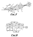
- a suitable neuro-net for this diagnosis is shown in Figure 8.
- boxes shown represent the following conditions: Key for Figure 8 Box No. Condition 31 non-standard shape 33 centre cross line bent 35 convex hull > filled image 37 bending downward 39 bending edge has similar arc degree to the bent cross 41 bending axis length > the other axis length 43 convex surface
- the input labelled FJ in Figure 8 represent a known fuzzy logic judge.
- Large object geometry is determined by scanning the spot beam or using a grid network or lines. The former requires a servo system and latter requires a large laser pattern generator or masks.
- Processing speed depends on camera scanning rate, frame grabbing speed and data processor hardware and software structure. For example, the normal CCD scanning rate is 25 frames of picture per second. Therefore the maximum processing rate is restricted by this value, ie 40ms upgrading rate. Parallel processing with multiple frame grabbers and cameras can increase this limit by factors of n through alternative sampling, where n is the number of camera systems.
- Range of sensing For continuous variation of the surface geometry the immediate next position sampled by the system should be within the imaging device frame range. For example a 752 x 582, 25Hz camera with magnification of 10 on a 14 inch TV screen (or 0.24 on a 0.5" image sensor), a 10mm spot on the object surface would allow the maximum displacement of the object of ⁇ 10mm within 40ms. Automatic adjustment of the system to the object surface would allow the sensing range to be extended.
- a 7mW HeNe laser with a red beam was used with optics of beam collimators (or beam expanders), beam diffusers/beam integrators and pattern generators (a structured mask) to project structured light on the object of interest.
- a video camera PULNIX TM-620 B/W 752x582 CCD was placed at an angle to the projected laser beam.
- An optical filter (narrow band at 632.8nm for a red HeNe laser) to allow the camera only response to the laser wavelength was used to eliminate the effect of background light.
- the image detected by the video camera was then analysed in real time by stand alone multiple array image processors with a parallel processing board (CENTURION).
- the processed information was then transmitted to a host computer (OPUS V PC 486) through serial lines (RS232) for further analysis and digital/graphic display.
- An on-line laser image surface monitoring and control system was realised using PASCAL 6.0 programming of the computer.
- a Menu driven keyboard VDU control system for the computer was implemented for parameter setup, load/save data, operating selection and real time process parameter display in both digital and graphic forms.
- An example of the system was used to determine automatic surface standoff, orientation, shape monitoring and closed loop standoff control during high power CO 2 laser processing of a stepped sample.
- a SHAPE FACTOR defined as the ratio between the length of longer axis (least momentum) and shorter axis (vertical to the least momentum) of the image was determined.
- a GEOMETRY factor was also determined having four possibilities: flat, convex, concave and irregular. Increasing the intensity of the laser beam gives better resolution since binary image calculation is used throughout.
Description
- The present invention relates to the determination of the surface properties of an object, in particular the remote, contactless determination of one or more of surface orientation, distance, displacement, shape or the presence of surface discontinuities such as walls, corners and holes.
- In many industrial applications, such as robotic welding and laser materials processing, it is necessary to maintain the processing head or heat source at a constant standoff and with constant orientation relative to the surface of the object to be treated. This is often achieved by programming the robotic device by human teaching to follow the surface contour. However, in situations requiring remote handling, eg servicing, repairing or decommissioning of a nuclear materials processing plant, it is necessary for the surface contour to be detected by the robot with sensors. This is difficult to achieve particularly when the object is irregular with corners, sharp bends and vertical walls. The previous techniques for detecting the surface contour profile have been by tactile probes connected to a position sensor such as a LVDT (Linear Variable Differential Transformer) or linear resistance potentiometer, or non-contact proximity switches or sensors such as capacitive (for metal surfaces only), inductive (for metal surfaces only) and photoelectric sensors. Recently diode laser triangulation has been used with PSD (position sensitive devices which are usually linear photoelectric sensor arrays). All these devices require either direct contact or a close proximity to the surface. None of these devices give the information on surface orientation. In fact the accuracy of most of the devices is affected by the surface orientation and materials properties. With robotic laser materials processing, for example, orientation of the beam with the surface can affect the beam absorption. Thus the consistency of the processing quality cannot be maintained without knowing this information. Also, the control of robotic movement with short distance proximity sensor feedback could be risky in the cases of sharp corners, holes and walls.
- A number of arrangements are described in the prior art which detect changes in the properties of a beam of optical radiation caused by reflection or scattering from the surface of an object to be investigated. The optical images formed on the object have been either one dimensional line images or simple two dimensional ring images and consequently it would not be possible to obtain suitable control information from such images. The effect of external lighting has not been considered in these prior art arrangements.
- In particular, GB 2241061A describes a technique wherein one or more beams are projected onto a rotating object. The beam is essentially one or more one-dimensional stripes and information such as surface orientation at a particular region of the surface is not obtained and cannot be obtained (without relative motion and repeated scanning of the beam).
- GB 2104652A discloses a method whereby a butt or seam on an object can be recognised during welding. Light in the form of a parallel line shaped grid is reflected from the object. There are no intersections between individual lines and the light structure is not therefore a truly two-dimensional and cannot be used to obtain orientation of the surface at the point of incidence. Also, the workpiece shape recognition resolution depends on the spacing of the projected grid lines. This system is suitable for an area shape recognition or location of features such as seams or butts rather than for on-line three dimensional tracking with orientation control. Also, possible influence of arc light on the sensing system may prevent the application of the device for real time applications. The system cannot provide multiple information such as x-y orientation, position and neighbourhood geometry at the same time for a spot on the workpiece surface.
- WO 9009560 describes an arrangement in which laser light is passed through a grating and a converging lens to project two columns of parallel grid lines of light on different parts of the object surface. Information about the surface is obtained by a ccd camera which allows the size difference of the two columns to be compared. This arrangement cannot be used to determine absolute position of the object surface or information about surface orientation.
- WO 8805904 describes an arrangement in which a line or multiple parallel lines of light are reflected from the surface of an object. Again, this arrangement cannot provide surface distance, surface orientation and surface neighbourhood information at the same time, ie from the same light beam.
- US 5150254 describes a device in which an endoscope tip is provided for conventional lighting on the surface of an object. The tip has to be located in close proximity to the object. Information about the surface position and orientation cannot be obtained using this device.
- US 4842411 describes an arrangement in which a series of parallel line beams are projected onto an object surface. This is not able to produce information about the surface at points between the projected lines, nor about the position and orientation of the surface.
- US 4411528 describes a device which projects a ring shaped light beam through a converging lens onto an object so that the size of the ring image projected on the surface, which changes with distance can be measured. The ccd camera used to detect the reflected image is co-axial with the light source. Since the measurement depends on the size of the image, it will depend upon surface reflectivity and colouring. A bright surface will give a bigger image and a dark surface will give a smaller image for the same distance.
- In "Polyhedral Face Reconstruction and Modeling from a Single Image with Structured Light" by Zen Chen et al, IEEE Trans. Systems, Man and Cybernetics, Vol. 23, No. 3 (May/June 1993), pages 864-872, there is described a method of determining the 3-D geometric model of visible polyhedral faces from a single view by analysis of the distortion introduced into a 2-D pattern of intersecting grid lines projected onto the faces, as viewed from a direction different from the projection direction. The method is described as "correspondenceless", insofar as the grid cell undergoing analysis does not need to be identified with a particular location in the generating grid.
- The present invention present a new approach to determine information such as the distance, displacement, orientation and shapes of the object surface of interest together with information on the presence of corners, holes and walls.
- According to the present invention there is provided a method for the determination of the properties of a surface of an object, said method comprising directing a beam of optical radiation from a source onto said surface, the two-dimensional intensity distribution of the beam in transverse cross-section defining an envelope and within the envelope an intensity structure which has multiple edges running in more than one direction, detecting an image of radiation scattered by the surface as viewed at a predetermined position angularly spaced about the object relative to the source, and performing an analysis of the intensity distribution in the detected digitised image relative to said intensity distribution of the incident beam to provide information regarding said surface properties, wherein said analysis includes comparison of the two-dimensional intensity distribution of said beam with the two-dimensional intensity distribution of said image to determine the displacement of at least one predetermined part of the image intensity distribution for the determination of the position of said surface.
- Signals produced by the analysis of said image in the method according to the invention may be used to control a device or manipulator to carry out operations on an object.
- In one application of the method of the invention, the object is thermally treated to form a meltpool or hot spot, and radiation radiated by the meltpool or hot spot is detected by a detector the output thereof being analysed to provide information concerning the meltpool or hot spot, which information is compared with the information regarding surface properties.
- The incident beam may comprise a collimated beam of laser or other light. Where a laser is employed it may be a solid state, gas or other laser. The structured cross-section or traced shape comprises a deliberately applied structure or shape such as a cross, cross in circle, cross in rectangle, multirectangular grid, multiple small circles in a larger circle, concentric circles, cross in a circle containing smaller circles or other distinctive structure.
- The means for producing an output beam may include, in addition to a radiation beam, eg laser, source, a beam expander and/or beam diffuser/integrator as well as an aperture providing the appropriate shape(s) for the cross-sectional structure of the emerging beam.
- The detector means for detecting scattered radiation may comprise a video camera (eg ccd camera) system or other known two-dimensional photodetector.
- The said signal processor may comprise a multiple array image processor, eg with a parallel processor, whose output is transmitted to a real time digital microcomputer, which together process and analyse the information comprising the image. The output of the computer may be applied to a display to form a visual image and/or transmitted to a remote receiver.
- Alternatively, a multiple camera system and/or multiple frame grabbing system may be employed. Such a remote detection device or system enables shape and position variation of the incident beam caused by the scattering surface to be analysed without movement of the beam source or the beam detector to give information about the inspected object, eg the distance, displacement, orientation or shape of the surface of the object.
- In order to reduce the effects of ambient light on the detected image, the output beam directed at the surface of interest may be applied in pulses by application of a suitable, eg square, control waveform to the power supplied to the beam source and the detector means and/or the signal processor may be modulated in synchronism with the output pulses in a known manner.
- In addition, a colour filter may be applied to filter radiation detected by the detector means in order to detect only radiation originating from the means for producing the output beam after reflection from the surface of interest.
- The present invention may conveniently be used in a wide number of applications including automatic robotic three dimensional surface processing, surface examination in engineering construction, geographical or space applications, or automatic quality control of manufactured components in a production line. The present invention is particularly useful in remote handling operations, eg the maintenance, repair or decommissioning of a nuclear materials processing or reprocessing facility. The output signal provided by the digital computer may be employed as an error control signal in a feedback loop control system to control the movement of a robotic device or manipulator that is used to move either the object being investigated or a means located adjacent to it, eg a laser source being employed to produce a laser beam to treat the surface.
- The means for producing an output beam and the detector means for detecting scattered radiation desirably subtend an acute angle (followed by the path of the incident and scattered radiation) at the inspected surface.
- The principle of operation of the invention is as follows. When the incident beam is shone on a object surface of interest in a structured spot an image is produced with a degree of contrast relative to the background environment, ie unilluminated regions of the surface. The beam image can be detected by the said detector and digitised and analysed and reconstructed by the signal processor. Since an angle exists between the incident and scattered radiation beam paths then the image viewed by the detector is the projection of the image on the object surface which is dependent on surface standoff distance to the detector, and geometries used in the arrangement. By analysing the shape and position of the detected image in comparison to the image projection known to be received from a standard flat surface the real object surface information such as stand-off, orientation and shape can be obtained. Generally speaking, the projection of the centre point of the incident beam spot is only dependent on the position or distance variation of the surface at that spot. The orientation of the image axis is dependent on the surface orientation and the shape of the image is dependent on the geometry of the surface.
- One of the distinct features of the system is that the scattered beam detection system, ie detector and signal processor, can be placed remotely from the object. The use of the incident, eg laser, beam enables the beam structure formed on the surface to be relatively consistent even at far field operation when a beam collimator is used. The image can be detected (or zoomed in) remotely using a video (such as a CCD) camera or other imaging device and a long focal length lens with an extension tube.
- The remote nature of the sensing system prevents potential hazards near the detection area such as flames, radiation, fumes, walls and obstacles. Thus useful information can be provided by computer to a manipulator such as a robotic processing machine for the appropriate adjustment to suit the surface profiles without running any risks of collision and damage.
- A second beneficial feature of the system is that the measurement is independent of surface materials property, thus no calibration is required for different applications. This is because the determination of surface parameters or geometries is by position and shape variations within the components of the detected scattered radiation image.
- A third beneficial feature of the system is that the object surface to be detected can be stationary or moving and no scanning of the incident beam is required to define the position and geometry of the object surface within the image formed. No relative movement between the optical source and detector is required.
- A fourth beneficial feature of the system is that multiple information such as surface position and geometry data including surface orientation can be obtained from the system at the same time. Information about large area surface topography can be obtained by scanning over the object.
- The surface being inspected may be one which is being treated by a laser beam or other heat source to produce meltpool or heated spot as described in our copending International Patent Application of even date, claiming priority from UK Patent Application No. 9323052.2. Such a meltpool or heated spot is strongly radiation-emitting and we have found that the radiation light emitted can be detected, digitised and analysed in a manner similar to that (described for example with reference to Figure 1 hereinafter) for the scattered laser beam. Such a procedure provides information about the position, orientation and standoff distance of the surface of the emitting hot spot or meltpool. The information produced in this way may be compared in the computer with that obtained in accordance with the present invention using the structured laser beam. The signals detected, digitised and analysed from the radiation emitted from the meltpool or hot spot provides information about the present position of a laser beam which is treating the surface of the object whereas the information obtained from the structured laser beam may be obtained from a surface position in advance of movement of the treatment site to that position.
- The present invention is particularly useful in remote handling operations, eg the maintenance, repair or decommissioning of a nuclear material processing or reprocessing facility.
- Embodiments of the present invention will now be described by way of example with reference to the accompanying drawings, in which:
- Figure 1 is a diagram, partly in block schematic form, of a system embodying the present invention.
- Figure 2 is a side elevation illustrating an example of a beam producer for use in the system shown in Figure 1;
- Figure 3 illustrates beam shapes which may be produced by the beam producer shown in Figure 2;
- Figure 4 illustrates various image shapes obtained from different object surface features in a system as shown in Figure 1;
- Figure 5 is an optical ray diagram illustrating the geometrical relationships between the actual displacement of the distance to the object surface and image position variation in a system as shown in Figure 1;
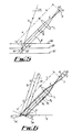
- Figure 6 is an optical ray diagram illustrating the geometrical relationships between angular displacement of the beam by the object surface and image dimension variation in a system as shown in Figure 1; illustrating the geometrical relationship between object surface orientation change and image variation in a system as shown in Figure 1;
- Figure 8 is a flow diagram illustrating a process of shape recognition using neural network logic useful in the system shown in Figure 1.
-
- Figure 1 shows a system for the remote sensing of surface orientation, displacement and shapes. A
laser source 1 provides anoutput beam 3 which is employed to gather information from asurface 5 of an object of interest. Thesurface 5 scatters thebeam 3 and thescattered beam 7 is detected by avideo camera system 9. Apower supply 11 is employed to energise thelaser source 1 and a power supply 13 (which could be combined with the supply 11) is employed to energise thecamera system 9. The output video signal provided by thecamera system 9 is captured by aunit 15 comprising a frame grabber and local image processor and is further processed by amicrocomputer 17. The output of themicrocomputer 17 may be displayed, eg on a visual display unit (not shown) and/or transmitted to a remote receiver (not shown). Asynchronisation control 19 provides a signal which synchronises modulation of the output of thepower supply 11 and thereby thelaser source 1 together with theframe grabber 15. - Figure 2 illustrates one form of optical arrangement which may be employed with the
laser source 1 of Figure 1. The output beam of thelaser source 1 is passed successively through abeam expander 21, a diffuser orbeam integrator 23 and a structured aperture 25 to form an enlarged beam 3a of structured cross-section providing astructured spot 28. The paths of the extremities of the optical output of thelaser source 1 are illustrated by lines X. - As illustrated in Figure 3(a) the aperture 25 has a transmitting
shape 29 comprising across 31 inside acircle 33. Thecross 31 andcircle 33 are also shown individually in Figure 3(b) and (c). The beam 3a therefore has a corresponding cross-section as illustrated by thespot 28 which is the spot which will be incident on the object surface 5 (Figure 1). Other shapes may be provided by replacing the aperture 25 with alternative apertures having different transmitting beam cross-sectional shapes. For example ashape 35 as in Figure 3(d) comprising a cross inside a square may be used. Theindividual components - Some examples of the various images formed by various features on a surface (eg surface 5) are shown in Figure 4. These examples show images formed by incidence of a laser beam (eg beam 3) structured as a cross-shape inside a
circle 29 as shown in Figure 4 on the surface (Figure 1). - In Figure 4,
Column 1 illustrates thelaser beam 3 incident on various surface features andColumn 2 illustrates the shape of the corresponding image formed in each case. The items shown inColumn 1 in Figure 4 are as follows:Figure 4 Key: Item No. Feature illustrated 1. Standoff distance variation 2. Tilted surface tilt, inward sense 3. Tilted surface tilt outward sense 4. Tilted surface tilt to right 5. Tilted surface tilt to left 6. Curved edge 7. Straight edge 8 Wall 9 Corner 10. Convex surface 11. Concave surface - The basic geometrical relationships of the system shown in Figure 1 and the factors that determine operating limits of the system are summarised as follows:
(1) The relationship between the image position and the object surface distance and displacement: As shown in Figure 5 the position of a single laser ray S (for example, the centre of the incident beam 3) incident on theobject surface 5 will vary as the distance changes. Three possible positions of theobject surface surface 5 in each case are focused by a lens L of focal length f and form an image in the image plane I of the video camera system 9 (Figure 1). The lens L is a distance u from the point at which the ray S strikes thesurface 5b. The distance from the lens L to the image plane I is a distance v. The distances between the point of impact of the ray S on thesurfaces surfaces 5b and 5c as measured along the path of the scattered ray R are a1 and a2 respectively. - The ratio between the image length on the
video camera system 9 at image plane I and the actual distance displacement (for example h1/d1 or h2/d2) can be found from the geometrical relationships as follows: - Since
- From Equation (3) the object surface displacement can be obtained through the position variation of a particular image point such as the centre of the
incident beam 3. Since the parameters on the right hand side of Equation (3) can be constant for a particular system, position variation of the projected image in the plane I is linearly proportional to the object surface displacement. A short focal length lens will give higher sensing resolution. Also, the bigger the angular difference between the incident and scattered beams the greater the resolution. The absolute distance can also be obtained by generating a small angular variation of the laser projection angle (α) to cause an image displacement. Since the image gain obtained from Equation (3) is equal to v/u where u is the distance between the camera lens L and theobject surface 5 as shown in Figure 5, the actual distance between the object and the camera can thus be easily calculated. Surface reflection and materials properties of thesurface 5 therefore do not affect the sensing. For very long distance sensing such as in the application of space engineering the divergence of the laser beam over distance will change the size of the incident laser beam image spot which could be used to evaluate the distance as well. - (2) Relationships between the angular displacement of the object and the length variation of the image: The surface orientation of the object surface and the angular displacements of the surface orientation can be described by the surface angle in the plane of the
source 1 and camera system 9 (γ) and the plane vertical to it (ω). - Reference symbols in Figure 6 which are the same as those used in Figure 5 have like meanings. In the case of Figure 6, the
surface 5 is shown to occupy twoalternative positions 5c and 5d at tilt angles γ1 and γ2 respectively to the original position. In this case the incident beam comprises rays S1, S2 and S3 and the scattered beam formed by reflections atsurfaces respective surfaces source 1/camera system 9 arrangements as shown if thesurface 5 tilts toward thecamera system 9 the length of image will increase and vice versa. Suppose the image length projected on a horizontal surface is h1 and the projection on the image plane I is d1 as shown in Figure 7. After an angular displacement of thesurface 5 the image length projected on thesurface 5 andvideo camera system 9 are h2 and d2 respectively. Then the relationship between the range of the length and the angular displacement γ of thesurface 5, in the plane of thesource 1 andsystem 9 can be found as follows:system 9 andsource 1 as follows:It can be proved that the angular displacement ωvertical to the plane containing the
source 1 andvideo camera system 9 is equivalent to the angular displacement of the principal axis of the spot image or the angular variation of the image. - (3) Sensing resolution and accuracy: This is dependent on the
video camera system 9 resolution, lens type, image spot size, and picture magnification. Generally speaking the sensing resolution increases with lens focal length, image camera resolution, angle betweenbeam source 1 andcamera system 9 and is reduced with image spot size. The higher the resolution of thecamera system 9, the longer the focal length the better resolution will be. For example, a camera providing 752 x 582 image elements would give 752 x 582 pixels for the whole TV monitor screen. If a spot size of 10mm square is represented on a 14 inch screen by a 100mm square occupying approximately 300 x 300 pixels, the resolution is 10mm/300 pixel = 33 micron/pixel. A second camera looking only at the cross centre of the image would give this accuracy for position displacement sensing. - (4) Image shape analysis for determination of presence of edges, walls and corners: From Figure 4 it can be seen that a projected circular beam spot can be badly distorted when there is a presence of edges, walls and corners. By comparing the distorted images with the known feature of the image pattern the presence of edges, walls and corners within the image spot range can be detected. An automatic recognition procedure can be employed using the following knowledge based rules (heuristics) and algorithms when the incident beam structure and image is divided into four equal parts by cross lines as illustrated as
item 29 in Figure 4. - Edges and holes: IF there is a reduction of image area and the cross lines are straight or piecewise linear and IF the area difference between the filled convex-hull and the filled image is positive (image area is not lost by internal holes)
THEN it is likely that there is an edge presence.
OTHERWISE there is one or many internal holes. Count number of holes. - The size of the area loss can be used to determine the extent the image position towards the edges or the average size of holes. A radial line length scan from the centre point to the image edges will give the exact location and shape of the edges by symmetrical analysis. An approximate position of the edge and holes can be obtained by locating the smaller areas of the four parts.
- Walls and corner walls: IF there is an increase of the image size and the cross lines are piecewise linear and IF there the difference between the filled convex-hull and filled image is greater than zero (or a given threshold value)
THEN there is a wall presence, - The distinction between straight walls and corner walls can be found by calculating the number of regions after the area difference (2 for straight walls and 3 for corner walls). Also by locating the geometric centre of the remaining regions (after the difference), location of the walls can be obtained.
- (5) Object 3-D geometry recognition: Local geometry of the object surface can be determined from the spot geometry of the beam spot on the surface as shown in Figure 4. A database of features of different standard geometry is stored in the computer. Comparison of real image with these image features allows the surface geometry to be determined using neural network analysis and fuzzy logic. For example a cylindrical object would distort the image such that the central cross lines or edge lines are arc rather than straight lines. A suitable neuro-net for this diagnosis is shown in Figure 8.
- In Figure 8, boxes shown represent the following conditions:
Key for Figure 8 Box No. Condition 31 non-standard shape 33 centre cross line bent 35 convex hull > filled image 37 bending downward 39 bending edge has similar arc degree to the bent cross 41 bending axis length > the other axis length 43 convex surface - In addition, the input labelled FJ in Figure 8 represent a known fuzzy logic judge. Large object geometry is determined by scanning the spot beam or using a grid network or lines. The former requires a servo system and latter requires a large laser pattern generator or masks.
- (6) Processing speed: The processing speed depends on camera scanning rate, frame grabbing speed and data processor hardware and software structure. For example, the normal CCD scanning rate is 25 frames of picture per second. Therefore the maximum processing rate is restricted by this value, ie 40ms upgrading rate. Parallel processing with multiple frame grabbers and cameras can increase this limit by factors of n through alternative sampling, where n is the number of camera systems.
- (7) Range of sensing: For continuous variation of the surface geometry the immediate next position sampled by the system should be within the imaging device frame range. For example a 752 x 582, 25Hz camera with magnification of 10 on a 14 inch TV screen (or 0.24 on a 0.5" image sensor), a 10mm spot on the object surface would allow the maximum displacement of the object of ±10mm within 40ms. Automatic adjustment of the system to the object surface would allow the sensing range to be extended.
- In a specific example of the use of a system as shown in Figure 1 a 7mW HeNe laser with a red beam was used with optics of beam collimators (or beam expanders), beam diffusers/beam integrators and pattern generators (a structured mask) to project structured light on the object of interest. A video camera (PULNIX TM-620 B/W 752x582 CCD) was placed at an angle to the projected laser beam. An optical filter (narrow band at 632.8nm for a red HeNe laser) to allow the camera only response to the laser wavelength was used to eliminate the effect of background light. The image detected by the video camera was then analysed in real time by stand alone multiple array image processors with a parallel processing board (CENTURION). The processed information was then transmitted to a host computer (OPUS V PC 486) through serial lines (RS232) for further analysis and digital/graphic display.
- An on-line laser image surface monitoring and control system was realised using PASCAL 6.0 programming of the computer. A Menu driven keyboard VDU control system for the computer was implemented for parameter setup, load/save data, operating selection and real time process parameter display in both digital and graphic forms. An example of the system was used to determine automatic surface standoff, orientation, shape monitoring and closed loop standoff control during high power CO2 laser processing of a stepped sample. A SHAPE FACTOR defined as the ratio between the length of longer axis (least momentum) and shorter axis (vertical to the least momentum) of the image was determined. A GEOMETRY factor was also determined having four possibilities: flat, convex, concave and irregular. Increasing the intensity of the laser beam gives better resolution since binary image calculation is used throughout.
Claims (11)
- A method for the determination of the properties of a surface of an object, said method comprising directing a beam of optical radiation from a source onto said surface, the two dimensional intensity distribution of the beam in transverse cross section defining an envelope and within the envelope an intensity structure which has multiple edges running in more than one direction, detecting an image of radiation scattered by the surface as viewed at a predetermined position angularly spaced about the object relative to the source, and performing an analysis of the intensity distribution in the detected digitised image relative to said intensity distribution of the incident beam to provide information regarding said surface properties, characterised in that said analysis includes comparison of the two-dimensional intensity distribution of said beam with the two-dimensional intensity distribution of said image to determine the displacement of at least one pre-determined part of the image intensity distribution for the determination of the position of said surface .
- A method according to Claim 1 wherein the source comprises a laser.
- A method according to Claim 1 or Claim 2, wherein at normal incidents, the intensity distribution of the beam defines a circular or rectangular envelope, and within said envelope across, a multi rectangular grid, or a plurality of circles.
- A method according to any preceding Claim, wherein the beam from the source is passed through a beam expander and/or a beam diffuser/integrator prior to falling on the surface.
- A method according to any preceding Claim, wherein the beam from the source is passed through an aperture to provide the required intensity distribution.
- A method according to any preceding Claim, wherein said detecting comprises the use of a video camera or other two-dimensional photodetector.
- A method according to any preceding Claim, wherein the incident beam is applied in pulses by application of a control waveform to the power supplied to the optical source, the image signal produced by the detector being referenced to a corresponding waveform.
- A method according to any preceding Claim, wherein radiation scattered by said surface is passed through an optical filter prior to detection.
- A method according to any preceding Claim, wherein said object is part of a nuclear plant or construction.
- A method of controlling a robotic device or manipulator to carry out operations on an object, comprising performing the method according to any preceding claim on said object, and using signals produced by said analysis of said image to control said device or manipulator.
- A method according to any preceding Claim, wherein said object is thermally treated to form a melt pool or hot spot, and including the further step of detecting radiation radiated by the melt pool or hot spot by a detector and analysing the output of said detector to provide information concerning the melt pool or hot spot, said information being compared with said information regarding said surface properties.
Applications Claiming Priority (3)
| Application Number | Priority Date | Filing Date | Title |
|---|---|---|---|
| GB939323054A GB9323054D0 (en) | 1993-11-09 | 1993-11-09 | Determination of the surface properties of an omject |
| GB9323054 | 1993-11-09 | ||
| PCT/GB1994/002451 WO1995013520A1 (en) | 1993-11-09 | 1994-11-08 | Determination of the surface properties of an object |
Publications (2)
| Publication Number | Publication Date |
|---|---|
| EP0678189A1 EP0678189A1 (en) | 1995-10-25 |
| EP0678189B1 true EP0678189B1 (en) | 2001-07-18 |
Family
ID=10744856
Family Applications (1)
| Application Number | Title | Priority Date | Filing Date |
|---|---|---|---|
| EP95900218A Expired - Lifetime EP0678189B1 (en) | 1993-11-09 | 1994-11-08 | Determination of the surface properties of an object |
Country Status (6)
| Country | Link |
|---|---|
| US (1) | US5714762A (en) |
| EP (1) | EP0678189B1 (en) |
| JP (1) | JPH08505703A (en) |
| DE (1) | DE69427747D1 (en) |
| GB (1) | GB9323054D0 (en) |
| WO (1) | WO1995013520A1 (en) |
Cited By (3)
| Publication number | Priority date | Publication date | Assignee | Title |
|---|---|---|---|---|
| DE102006002077A1 (en) * | 2006-01-13 | 2007-07-26 | GOM - Gesellschaft für Optische Meßtechnik mbH | Device and method for three-dimensional optical measurement |
| EP3009886B1 (en) * | 2014-10-17 | 2018-01-31 | Ricoh Company, Ltd. | Handling system |
| EP3199911B1 (en) * | 2016-01-27 | 2018-10-31 | Ricoh Company, Ltd. | System comprising a three-dimensional measuring apparatus |
Families Citing this family (28)
| Publication number | Priority date | Publication date | Assignee | Title |
|---|---|---|---|---|
| US5917655A (en) * | 1998-04-06 | 1999-06-29 | Motorola, Inc. | Method and apparatus for generating a stereoscopic image |
| US5982493A (en) * | 1998-06-02 | 1999-11-09 | Motorola, Inc. | Apparatus and method for acquiring multiple images |
| US6301549B1 (en) * | 1998-06-26 | 2001-10-09 | Lucent Technologies, Inc. | Three dimensional object boundary and motion determination device and method of operation thereof |
| US6553138B2 (en) | 1998-12-30 | 2003-04-22 | New York University | Method and apparatus for generating three-dimensional representations of objects |
| US6381026B1 (en) | 1999-03-15 | 2002-04-30 | Lifecell Corp. | Method of measuring the contour of a biological surface |
| US6441340B1 (en) * | 1999-05-04 | 2002-08-27 | Elizabeth Varriano-Marston | Registered microperforated films for modified/controlled atmosphere packaging |
| EP1067362A1 (en) | 1999-07-09 | 2001-01-10 | Hewlett-Packard Company | Document imaging system |
| EP1067757A1 (en) | 1999-07-09 | 2001-01-10 | Hewlett-Packard Company | Curled surface imaging system |
| US6421418B1 (en) | 2000-08-15 | 2002-07-16 | Northrop Grumman Corporation | Method and system for detecting hidden edges |
| JP3424001B2 (en) * | 2000-12-28 | 2003-07-07 | 川崎重工業株式会社 | Laser welding method and laser welding apparatus |
| US6836362B2 (en) | 2001-05-14 | 2004-12-28 | General Electric Company | Method for the rapid determination of the optical quality of combinatorial libraries |
| DE10341959B4 (en) * | 2003-09-11 | 2007-05-31 | Deutsches Zentrum für Luft- und Raumfahrt e.V. | Method for measuring a surface relative to a reference surface |
| US20050169346A1 (en) * | 2004-01-29 | 2005-08-04 | Trw Automotive U.S. Llc | Method for monitoring quality of a transmissive laser weld |
| US7433023B2 (en) * | 2004-09-20 | 2008-10-07 | Applied Kinetics, Inc. | Apparatuses and methods for measuring head suspensions and head suspension assemblies |
| KR100797239B1 (en) * | 2005-12-23 | 2008-01-23 | 주식회사 포스코 | Apparatus and method for on-line detecting welding part of strip |
| CN101460863B (en) * | 2006-04-05 | 2012-06-06 | 加利福尼亚州技术学院 | 3- dimensional imaging by acoustic warping and defocusing |
| US7916309B2 (en) | 2007-04-23 | 2011-03-29 | California Institute Of Technology | Single-lens, single-aperture, single-sensor 3-D imaging device |
| US8089635B2 (en) | 2007-01-22 | 2012-01-03 | California Institute Of Technology | Method and system for fast three-dimensional imaging using defocusing and feature recognition |
| AU2008209480A1 (en) * | 2007-01-22 | 2008-07-31 | California Institute Of Technology | Method for quantitative 3-D imaging |
| WO2010027391A2 (en) | 2008-08-27 | 2010-03-11 | California Institute Of Technology | Method and device for high-resolution three-dimensional imaging which obtains camera pose using defocusing |
| US8773507B2 (en) * | 2009-08-11 | 2014-07-08 | California Institute Of Technology | Defocusing feature matching system to measure camera pose with interchangeable lens cameras |
| US8773514B2 (en) * | 2009-08-27 | 2014-07-08 | California Institute Of Technology | Accurate 3D object reconstruction using a handheld device with a projected light pattern |
| US8939107B2 (en) * | 2010-02-26 | 2015-01-27 | Purdue Research Foundation | Confined pulsed laser deposition method for depositing metastable thin film |
| CN103221975B (en) | 2010-09-03 | 2017-04-19 | 加州理工学院 | Three-dimensional imaging system |
| US20130010068A1 (en) * | 2011-04-12 | 2013-01-10 | Radiation Monitoring Devices, Inc. | Augmented reality system |
| WO2014022426A1 (en) * | 2012-07-30 | 2014-02-06 | State Of Oregon Acting By And Through The State Boad Of Higher Education On Behalf Of Oregon State University | Apparatus and method for determining molecular structure |
| WO2017132165A1 (en) | 2016-01-25 | 2017-08-03 | California Institute Of Technology | Non-invasive measurement of intraocular pressure |
| US10542245B2 (en) * | 2017-05-24 | 2020-01-21 | Lg Electronics Inc. | Mobile terminal and method for controlling the same |
Family Cites Families (16)
| Publication number | Priority date | Publication date | Assignee | Title |
|---|---|---|---|---|
| JPS57108705A (en) * | 1980-12-26 | 1982-07-06 | Kawasaki Steel Corp | Method and device for monitor of bead cut form at welded part on inner surface of welded tube |
| US4411528A (en) * | 1981-01-19 | 1983-10-25 | Control Data Corporation | Optical displacement and contour measuring |
| US4412121A (en) * | 1981-08-28 | 1983-10-25 | S R I International | Implement positioning apparatus and process |
| US4409478A (en) * | 1982-02-26 | 1983-10-11 | Automatix Incorporated | Method and apparatus for image acquisition utilizing a concave, cylindrical reflector |
| JPS59188509A (en) * | 1983-04-11 | 1984-10-25 | Nippon Telegr & Teleph Corp <Ntt> | Recognition system of position and shape of body |
| US4674875A (en) * | 1983-12-09 | 1987-06-23 | Hitachi, Ltd. | Method and apparatus for inspecting surface defects on the magnetic disk file memories |
| US4731855A (en) * | 1984-04-06 | 1988-03-15 | Hitachi, Ltd. | Pattern defect inspection apparatus |
| JPH0820230B2 (en) * | 1984-06-08 | 1996-03-04 | オリンパス光学工業株式会社 | Measuring endoscope |
| US4842411A (en) * | 1986-02-06 | 1989-06-27 | Vectron, Inc. | Method of automatically measuring the shape of a continuous surface |
| US4791482A (en) * | 1987-02-06 | 1988-12-13 | Westinghouse Electric Corp. | Object locating system |
| WO1990009560A1 (en) * | 1989-02-17 | 1990-08-23 | John Lysaght (Australia) Limited | Distance gauge |
| JPH02287311A (en) * | 1989-04-28 | 1990-11-27 | Toshiba Corp | Endoscope device with measuring mechanism |
| US5054907A (en) * | 1989-12-22 | 1991-10-08 | Phoenix Laser Systems, Inc. | Ophthalmic diagnostic apparatus and method |
| US5054918A (en) * | 1990-02-02 | 1991-10-08 | Fmc Corporation | Light scanning system for measurement of orientation and physical features of a workpiece |
| JP2722362B2 (en) * | 1992-03-27 | 1998-03-04 | 三井金属鉱業株式会社 | Method and apparatus for measuring particle or defect size information |
| US5426506A (en) * | 1993-03-22 | 1995-06-20 | The University Of Chicago | Optical method and apparatus for detection of surface and near-subsurface defects in dense ceramics |
-
1993
- 1993-11-09 GB GB939323054A patent/GB9323054D0/en active Pending
-
1994
- 1994-11-08 JP JP7513674A patent/JPH08505703A/en not_active Ceased
- 1994-11-08 DE DE69427747T patent/DE69427747D1/en not_active Expired - Lifetime
- 1994-11-08 EP EP95900218A patent/EP0678189B1/en not_active Expired - Lifetime
- 1994-11-08 US US08/481,369 patent/US5714762A/en not_active Expired - Fee Related
- 1994-11-08 WO PCT/GB1994/002451 patent/WO1995013520A1/en active IP Right Grant
Cited By (3)
| Publication number | Priority date | Publication date | Assignee | Title |
|---|---|---|---|---|
| DE102006002077A1 (en) * | 2006-01-13 | 2007-07-26 | GOM - Gesellschaft für Optische Meßtechnik mbH | Device and method for three-dimensional optical measurement |
| EP3009886B1 (en) * | 2014-10-17 | 2018-01-31 | Ricoh Company, Ltd. | Handling system |
| EP3199911B1 (en) * | 2016-01-27 | 2018-10-31 | Ricoh Company, Ltd. | System comprising a three-dimensional measuring apparatus |
Also Published As
| Publication number | Publication date |
|---|---|
| DE69427747D1 (en) | 2001-08-23 |
| WO1995013520A1 (en) | 1995-05-18 |
| US5714762A (en) | 1998-02-03 |
| GB9323054D0 (en) | 1994-01-05 |
| JPH08505703A (en) | 1996-06-18 |
| EP0678189A1 (en) | 1995-10-25 |
Similar Documents
| Publication | Publication Date | Title |
|---|---|---|
| EP0678189B1 (en) | Determination of the surface properties of an object | |
| CA1059752A (en) | Gauging surfaces by remotely tracking multiple images | |
| EP1206676B1 (en) | Optical sub-pixel parts inspection system | |
| US6313948B1 (en) | Optical beam shaper | |
| US4629319A (en) | Panel surface flaw inspection | |
| AU616731B2 (en) | Method and apparatus for monitoring the surface profile of a moving workpiece | |
| US7009713B2 (en) | Optical position measuring system using an interference pattern | |
| US5748311A (en) | Apparatus and method of particle geometry measurement by speckle pattern analysis | |
| US4920385A (en) | Panel surface flaw inspection | |
| IL138414A (en) | Apparatus and method for optically measuring an object surface contour | |
| US6636310B1 (en) | Wavelength-dependent surface contour measurement system and method | |
| US4498776A (en) | Electro-optical method and apparatus for measuring the fit of adjacent surfaces | |
| US20210278347A1 (en) | Machine direction line film inspection | |
| Saeed et al. | Mathematical formulation and simulation of specular reflection based measurement system for gas tungsten arc weld pool surface | |
| JPH0769161B2 (en) | Method and apparatus for inspecting uneven surface | |
| Umeagukwu et al. | Investigation of an array technique for robotic seam tracking of weld joints | |
| JP2899875B2 (en) | Non-contact surface roughness measuring method and its measuring device | |
| JPS5880510A (en) | Automatic measuring device for ridgeline coordinates | |
| GB2157419A (en) | Optical sensor for for use in controlling a robot | |
| RU2800540C2 (en) | Control line for empty glass containers | |
| Ai et al. | Study on image acquisition in 3-d sensor system of arc welding pool surface shape using grating projection | |
| JPS62222117A (en) | Multipoint distance measuring sensor | |
| Wu et al. | An imaging system with structured lighting for on‐line generic sensing of three‐dimensional objects | |
| CA1245889A (en) | Three dimensional imaging method and device | |
| KR101187647B1 (en) | High level alpha/beta Contamination Visualization Method and System Thereof |
Legal Events
| Date | Code | Title | Description |
|---|---|---|---|
| PUAI | Public reference made under article 153(3) epc to a published international application that has entered the european phase |
Free format text: ORIGINAL CODE: 0009012 |
|
| 17P | Request for examination filed |
Effective date: 19950628 |
|
| AK | Designated contracting states |
Kind code of ref document: A1 Designated state(s): DE FR GB IT NL |
|
| 17Q | First examination report despatched |
Effective date: 19970804 |
|
| GRAG | Despatch of communication of intention to grant |
Free format text: ORIGINAL CODE: EPIDOS AGRA |
|
| GRAG | Despatch of communication of intention to grant |
Free format text: ORIGINAL CODE: EPIDOS AGRA |
|
| GRAH | Despatch of communication of intention to grant a patent |
Free format text: ORIGINAL CODE: EPIDOS IGRA |
|
| GRAH | Despatch of communication of intention to grant a patent |
Free format text: ORIGINAL CODE: EPIDOS IGRA |
|
| GRAA | (expected) grant |
Free format text: ORIGINAL CODE: 0009210 |
|
| AK | Designated contracting states |
Kind code of ref document: B1 Designated state(s): DE FR GB IT NL |
|
| PG25 | Lapsed in a contracting state [announced via postgrant information from national office to epo] |
Ref country code: NL Free format text: LAPSE BECAUSE OF FAILURE TO SUBMIT A TRANSLATION OF THE DESCRIPTION OR TO PAY THE FEE WITHIN THE PRESCRIBED TIME-LIMIT Effective date: 20010718 Ref country code: IT Free format text: LAPSE BECAUSE OF FAILURE TO SUBMIT A TRANSLATION OF THE DESCRIPTION OR TO PAY THE FEE WITHIN THE PRESCRIBED TIME-LIMIT;WARNING: LAPSES OF ITALIAN PATENTS WITH EFFECTIVE DATE BEFORE 2007 MAY HAVE OCCURRED AT ANY TIME BEFORE 2007. THE CORRECT EFFECTIVE DATE MAY BE DIFFERENT FROM THE ONE RECORDED. Effective date: 20010718 Ref country code: FR Free format text: LAPSE BECAUSE OF FAILURE TO SUBMIT A TRANSLATION OF THE DESCRIPTION OR TO PAY THE FEE WITHIN THE PRESCRIBED TIME-LIMIT Effective date: 20010718 |
|
| REF | Corresponds to: |
Ref document number: 69427747 Country of ref document: DE Date of ref document: 20010823 |
|
| PG25 | Lapsed in a contracting state [announced via postgrant information from national office to epo] |
Ref country code: DE Free format text: LAPSE BECAUSE OF FAILURE TO SUBMIT A TRANSLATION OF THE DESCRIPTION OR TO PAY THE FEE WITHIN THE PRESCRIBED TIME-LIMIT Effective date: 20011019 |
|
| PG25 | Lapsed in a contracting state [announced via postgrant information from national office to epo] |
Ref country code: GB Free format text: LAPSE BECAUSE OF NON-PAYMENT OF DUE FEES Effective date: 20011108 |
|
| EN | Fr: translation not filed | ||
| REG | Reference to a national code |
Ref country code: GB Ref legal event code: IF02 |
|
| NLV1 | Nl: lapsed or annulled due to failure to fulfill the requirements of art. 29p and 29m of the patents act | ||
| PLBE | No opposition filed within time limit |
Free format text: ORIGINAL CODE: 0009261 |
|
| STAA | Information on the status of an ep patent application or granted ep patent |
Free format text: STATUS: NO OPPOSITION FILED WITHIN TIME LIMIT |
|
| GBPC | Gb: european patent ceased through non-payment of renewal fee |
Effective date: 20011108 |
|
| 26N | No opposition filed |