EP0680801A1 - Working liquid detecting apparatus, for wire-cut electric discharge machines - Google Patents
Working liquid detecting apparatus, for wire-cut electric discharge machines Download PDFInfo
- Publication number
- EP0680801A1 EP0680801A1 EP94931202A EP94931202A EP0680801A1 EP 0680801 A1 EP0680801 A1 EP 0680801A1 EP 94931202 A EP94931202 A EP 94931202A EP 94931202 A EP94931202 A EP 94931202A EP 0680801 A1 EP0680801 A1 EP 0680801A1
- Authority
- EP
- European Patent Office
- Prior art keywords
- working fluid
- electrode
- specific resistance
- fluid
- detective
- Prior art date
- Legal status (The legal status is an assumption and is not a legal conclusion. Google has not performed a legal analysis and makes no representation as to the accuracy of the status listed.)
- Granted
Links
Images
Classifications
-
- B—PERFORMING OPERATIONS; TRANSPORTING
- B23—MACHINE TOOLS; METAL-WORKING NOT OTHERWISE PROVIDED FOR
- B23H—WORKING OF METAL BY THE ACTION OF A HIGH CONCENTRATION OF ELECTRIC CURRENT ON A WORKPIECE USING AN ELECTRODE WHICH TAKES THE PLACE OF A TOOL; SUCH WORKING COMBINED WITH OTHER FORMS OF WORKING OF METAL
- B23H1/00—Electrical discharge machining, i.e. removing metal with a series of rapidly recurring electrical discharges between an electrode and a workpiece in the presence of a fluid dielectric
- B23H1/10—Supply or regeneration of working media
Definitions
- the present invention relates to a wire cut electric discharge machine, and in particular, to a working fluid detective device for detecting a specific resistance and a fluid level of a working fluid in a wire cut electric discharge machine.
- water is usually used as a working fluid in a wire cut electric discharge machine.
- the working fluid requires keeping predetermined conductivity.
- the working fluid is controlled by means of an ion exchanger so that its specific resistance is detected, and becomes a constant value.
- the specific resistance of working fluid gradually lowers as electric discharge machining progresses.
- the specific resistance of working fluid is detected by means of a specific resistance detector. If the detected specific resistance is less than a preset value, the specific resistance of working fluid is enhanced by subjecting the working fluid to the ion exchanger, and the working fluid is controlled so that its specific resistance is kept to a predetermined value.
- a working fluid having low specific resistance is suitable for machining a workpiece, in dependence on a quality of the workpiece.
- working fluid has specific resistance of a degree of 1 ⁇ 2 ⁇ 104 ⁇ cm.
- working fluid has a relatively high specific resistance of a degree of 3 ⁇ 10 ⁇ 104 ⁇ cm.
- tap water (its specific resistance is usually a degree of 0.5 ⁇ 104 ⁇ cm) is injected into a working fluid tank to execute the machining operation.
- the working fluid in the working fluid tank is supplied to a nozzle through a discharge pump, and fed from the nozzle to a wire, thus electric discharge machining being executed. Then, the working fluid is used for the electric discharge machining, and thereafter, again returned to the working fluid tank through a filter, etc.
- a fluid level detector such as a float switch detects a fluid level to prevent an air from being sucked in the tank due to a lower in the fluid level when the working fluid of the tank is discharged.
- An object of the present invention is to provide a working fluid detective device in a wire cut electric discharge machine, which is capable of detecting specific resistance and fluid level of a working fluid by the only one detector.
- one working fluid detector is composed of an electrocle located on a position capable of being immersed in the working fluid in the working fluid tank. At least one of the electrodes composing the working fluid detector has at least part located in a detective fluid level of the working fluid, so that a fluid level in the located position is detected.
- the working fluid detector having the aforesaid configuration, at least part of electrodes included in the detector is immersed in the working fluid, and a current flowing through the working fluid is detected, thereby the detector detecting specific resistance of working fluid in the vicinity of the electrodes.
- the working fluid detector located in the working fluid tank detects two detective items, that is, a fluid level and a specific resistance of the working fluid by the only one detector.
- a fluid level detection of the working fluid is effected by detecting an insulated state between the electrodes and the working fluid.
- a specific resistance detection of the working fluid is effected by detecting a resistance of the working fluid in the vicinity of the electrodes. In the detection of fluid level and specific resistance of the working fluid, there is the difference distinguishable both detection from one another between their detective outputs.
- a working fluid detector is composed of electrodes located in a position capable of being immersed in the working fluid in the working fluid tank. At least part of at least one of the electrodes composing the working fluid detector is located in a position preset as a detective fluid level of working fluid. When the working fluid is gradually reduced in the working fluid tank and the electrodes is immersed in the working fluid at the preset position, the electrodes are in a state insulated from each other. Then, the detector outputs a detective value corresponding to the insulated state, and detects a reduction in the working fluid.
- the electrodes When the working fluid is increased in the working fluid tank, the electrodes are immersed in the working fluid. Immersion of the electrodes makes, the insulated state between the electrodes release. At this time, the working fluid detector outputs a detective value different from that of the aforesaid insulated state. An output indicative of a state that the electrodes are immersed in the working fluid is equivalent to the specific resistance of working fluid. Therefore, the specific resistance of working fluid is detected on the basis of the detective value.
- the detector of the present invention can detect two detective items, that is, a fluid level and a specific resistance of the working fluid by the only one detector.
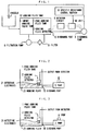
- FIG. 1 showing a block diagram of one embodiment according to the present invention, the constitution of embodiment will be described below.
- reference numerals 1 and 5 denote a pure working fluid tank and an impure working fluid tank of a working fluid tank 12, respectively.
- a discharge pump 3 supplies a pure working fluid from the pure working fluid tank 1 to a nozzle 4 of an electric discharge machining section, and ejects the pure working fluid to a gap between a wire of the electric discharge machining section and a workpiece from the nozzle 4.
- the working fluid passed through the electric discharge machining section becomes an impure fluid, and is recovered in the impure working fluid tank 5.
- the impure fluid recovered in the tank 5 is pumped up by means of a filtration pump 8, and returned to the tank 1 after sludge or the like is removed by passing the impure fluid through a filter 9.
- a discharge port 10 is formed on a side wall near the bottom of the pure working fluid tank 1.
- a pipe extending from the discharge pump 3 is connected to the discharge port 10.
- a working fluid detector 2 is located in a position near to a height equivalent to a fluid level of the discharge port 10.
- the working fluid detector 2 functions as a detector for measuring a fluid level and specific resistance of the working fluid in the pure working fluid tank 1, and includes a plurality of detection electrodes. In the case where the working fluid is sufficiently filled in the tank 1, the working fluid detector 2 measures the specific resistance of working fluid; on the other hand, in the case where the working fluid is reduced and the fluid level thereof reaches the vicinity of the discharge port 10, the detector 2 detects information that the fluid level of working fluid reaches the vicinity of the discharge port 10.
- An output from the working fluid detector 2 is transmitted to an NC unit 7 through a detection circuit 6.
- the NC unit 7 is one of components generally provided in an electric discharge machine, and a CPU of the NC unit 7 processes the output from the detective electrode 2, thus controlling specific resistance and fluid level of the working fluid.
- the specific resistance of working fluid is controlled by driving a specific resistance control section 11 on the basis of an output from the NC unit 7. More specifically, the specific resistance of working fluid is enhanced by controlling the drive of a solenoid valve of an ion exchanger connected to the pure working fluid tank 1, or is lowered by supplying tap water to the pure working fluid tank 1 by controlling the drive of the solenoid valve.
- the control for the specific resistance of working fluid is known in the prior art; therefore, the detailed explanation thereof is omitted herein.
- Fig. 2 shows a state that a working fluid is sufficiently filled in the tank 1 and the working fluid detector 2 detects the specific resistance of working fluid.
- Fig. 3 shows a state that the working fluid is reduced and the working fluid detector 2 detects whether or not the working fluid is situated on a preset fluid level.
- the working fluid detector 2 comprises two electrodes 21, and these electrodes 21 are located so as to be immersed in the working fluid in the pure working fluid tank 1.
- Fig. 2 shows a state that the specific resistance of working fluid is detected by means of the working fluid detector 2. More specifically, two electrodes 21 are immersed in the working fluid in the pure working fluid tank 1, and specific resistance of the working fluid between two electrodes 21 can be detected. Thus, not only the specific resistance of working fluid is detected, but also information that the working fluid is situated on a preset fluid level is detected. An output from the working fluid detector 2 is outputted to a detector circuit 6 shown in Fig. 1. In this case, when the working fluid detector 2 is in a state of being immersed in the working fluid, the discharge pump 3 is driven while supplying the working fluid in the pure working fluid tank 1 to the nozzle.
- Fig. 3 shows a state that the working fluid is reduced to the preset fluid level or less, and the lower in the fluid level is detected by means of the working fluid detector 2.
- at least one of two electrodes 21 is situated on a fluid level which is not immersed in the working fluid in the pure working fluid tank 1, and two electrodes 21 are in a state of being insulated from one another. If the insulation between the electrodes 21 is detected, a detection is made such that the working fluid reaches a preset fluid level.
- a fluid level detected by the working fluid detector 2 is set according to the position where the electrodes 21 is located in the pure working fluid tank 1, namely according to the height such that at least one of the electrodes 21 is not immersed in the working fluid in the tank.
- the discharge pump 3 is stopped according to the detection output to prevent an air from being sucked.
- the detective electrodes 21 is located so that their distal end portions directed downward is situated on a position slightly above from the upper end portion of the discharge port 10 connecting to the discharge pump 3.
- the fluid level is set so that an air does not enter into the discharge port 10.
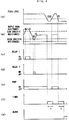
- Fig. 4 is a time chart of one embodiment of the present invention shown in Fig. 1. The following is the description of an operation of the working fluid detective device based on the time chart.
- Fig. 4(a) shows a fluid level of pure working fluid tank 1; Fig. 4(b) showing an output from the electrodes of working fluid detector; Fig. 4(c) and (d) showing a relay output for controlling specific resistance; Fig. 4(e) showing a drive signal for driving the discharge pump; Fig. 4(f) showing an output from a timer located in the NC unit; and Fig. 4(g) showing an output from an alarm.
- a broken line represents a preset fluid level in which the electrodes 21 detect a lower in a fluid level of working fluid. If the fluid level of working fluid is higher than the preset fluid level, the electrodes 21 are immersed in the working fluid. Conversely, if the fluid level of working fluid is lower than the preset fluid level, the electrodes 21 are not immersed in the working fluid; for this reason, the electrodes 21 are in a state of being insulated from each other.
- the electrodes 21 are immersed in the working fluid until time 1 and between time 2 and time 3 in the figure; the electrodes 21 are situated at a position separating from the working fluid between time 1 and time 2 in the figure.
- the electrodes 21 are immersed in the working fluid until time 1 and between time 2 and time 3; therefore, the output from the electrode shows specific resistance of the working fluid.
- the electrodes 21 are in a state of being insulated from each other between time 1 and time 2 and after time 3.
- a two-dot chain line represents a preset value when preset specific resistance is high and a preset value when preset specific resistance is low
- a dotted chain line represents a preset value indicative of an insulated state.
- the specific resistance of working fluid for electric discharge machining is controlled so that it is set between two preset specific resistances. In such specific resistance control, electric discharge machining is executed within a preset range of specific resistance sandwiched between two-dot chain lines.
- a relay 1 (not shown in Fig. 1) is turned on (see Fig. 4(c)), and control is started to increase specific resistance. If the specific resistance output is increased according to the control, it again exceeds the preset value of low specific resistance at time 5, and returns to the preset range sandwiched between two-dot chain lines. If the specific resistance output is further increased and exceeds a preset value of high specific resistance at time 6, a relay 2 (not shown in Fig. 1) is turned on (see Fig. 4(d)); conversely, control is started to decrease the specific resistance. If the specific resistance is decreased according to the control, the specific resistance output again exceeds the preset value of high specific resistance at time 7, and returns to the preset range sandwiched between two-dot chain lines.
- the fluid level thereof approaches the vicinity of the discharge port. If the fluid level exceeds downward the preset fluid level, the electrodes 21 are in a state being insulated from each other. The electrode output at this time becomes the preset value indicative of an insulated state shown by the dotted chain line in Fig. 4(b).
- the NC unit 7 makes a comparison between the electrode output and a preset value indicative of an insulated state. Then, the NC unit 7 detects a lower in the fluid level while outputting a control signal to stop the discharge pump. The control signal changes over the discharge pump 3 from on to off, as shown in Fig. 4(e), and the discharge pump is stopped.
- control is executed to rise the fluid level of working fluid (not shown).
- control is executed to rise the fluid level of working fluid and the working fluid again becomes higher than the preset fluid level at time 2 within a predetermined time T counted by a timer (not shown) included in the NC unit 7, the discharge pump 3 starts to drive, and the working fluid is again supplied to the nozzle.
- the NC unit 7 detects a lower in the fluid level while outputting a control signal to stop the discharge pump.
- the control signal changes over the discharge pump 3 from on to off, as shown in Fig. 4(e), and the discharge pump is stopped.
- an alarm signal is outputted as shown in Fig. 4(g), and it is indicative that a fault occurs in fluid level control.
- the specific resistance control described above is one embodiment of control over the specific resistance, and is not limited to this one.
- the alarm shown in Fig. 4(g) may be used in not only a warning against a failure in fluid level control but also control for compensating a fluid level of working fluid of a wire cut electric discharge machine.
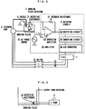
- a detector circuit 6 shown by a broken line includes an amplifier circuit 63 for amplifying an output from the working fluid detector 2, a rectifier circuit 64 for rectifying an alternating-current output from the amplifier circuit 63, a smoothing circuit 65 for smoothing an output from the rectifier circuit 64, and an A/D converter circuit 66 for converting an analog output from the smoothing circuit 65 into a digital output.
- the digital output from the A/D converter circuit 66 is transmitted to the NC unit 7.
- the amplifier circuit 63 outputs a signal corresponding to a resistance between the electrodes 21 of the working fluid detector 2. If a resistance between the electrodes 21 of the working fluid detector 2 is set as “r”, the amplifier circuit amplifies a voltage depending on the resistance "r”, and outputs it as a detection output.
- the resistance "r” shows a variation in specific resistance of the working fluid between the electrodes 21 or an insulated state between them. Based on the resistance "r", the specific resistance of working fluid and a lower in the fluid level thereof are detected.
- the amplifier circuit 63 is composed of an operation amplifier 60.
- the electrodes 21 are connected to a minus terminal side of the operation amplifier 60, and an alternating-current power source 62 is connected to a plus terminal side of the operation amplifier 60.
- a feedback resistor 61 is connected between the minus terminal side of the operation amplifier 60 and an output terminal of the operation amplifier 60.
- a peak value of the voltage of the alternating-current power source 62 in the amplifier circuit 63 is set as Vi and an output from the amplifier circuit 63 is set as Vo
- the output Vo detected in the fluid level state shown in Fig. 2 is determined on the basis of a resistance "r" between the electrodes 21 corresponding to the specific resistance of working fluid.
- the detection output Vo is converted into a signal by means of the rectifier circuit 64, smoothing circuit 65 and A/D converter circuit 65 to obtain a digital value.
- the digital value thus obtained and a value preset in accordance with specific resistance are compared by means of the NC unit 7, thereby executing control for the specific resistance of working fluid.
- an output Vo detected in the fluid level state shown in Fig. 3 equals to Vi which is a peak value of the voltage of the AC power source 62 because there is an insulated state between the electrodes 21; for this reason, a resistance "r" between them becomes an infinite value.
- the detection output Vo is converted into a signal by means of the rectifier circuit 64, smoothing circuit 65 and A/D converter circuit 65 to obtain a digital value.
- the digital value thus obtained and a value Vi preset for a detection of a lower in the fluid level are compared by means of the NC unit 7, thereby a lower in the fluid level of working fluid being detected, and the discharge pump 3 being stopped according to the detection.
- a comparative value preset in the NC unit 7 may be modified in accordance with control contents and configuration of the amplifier 63.
- the detective electrode 21 is arranged so that its electrodes are directed downward.
- a detective electrode 22 is arranged so that its electrodes are directed to the lateral direction (horizontal direction) with respect to the working fluid.
- the lateral direction arrangement one of two electrodes, which is situated upward, detects a lower in the fluid level, and a position of the upward electrode is equivalent to a preset position for detecting a fluid level.
- the other of two electrodes, which is situated downward is the inner wall itself of the tank or is located on a position near the inner wall thereof.
- a length of the electrode immersed in the working fluid is always kept constant regardless of a fluid level of the working fluid in detecting specific resistance; therefore, there is no variation in the specific resistance caused due to the difference in length of the electrode immersed in the working fluid.
- a using electrode is selected from the electrodes located at a different height
- a height for detecting a fluid level can readily be changed.
- a using electrode is selected from the detection electrodes located at the same height and on a different position
- a variation in specific resistance of a position in the tank can be compensated.
- the fluid level of working fluid does not rise within a predetermined time after it is lowered to a preset level or less, this is detected, and a detection is made that there is a failure in fluid level control of the working fluid.
- the present invention can provide a working fluid detective device in wire cut electric discharge machine, which is capable of detecting specific resistance and fluid level of working fluid by the only one detector.
Abstract
Description
- The present invention relates to a wire cut electric discharge machine, and in particular, to a working fluid detective device for detecting a specific resistance and a fluid level of a working fluid in a wire cut electric discharge machine.
- Conventionally, water is usually used as a working fluid in a wire cut electric discharge machine. In this case, the working fluid requires keeping predetermined conductivity. For this reason, the working fluid is controlled by means of an ion exchanger so that its specific resistance is detected, and becomes a constant value.
- Generally, the specific resistance of working fluid gradually lowers as electric discharge machining progresses. In such a case, the specific resistance of working fluid is detected by means of a specific resistance detector. If the detected specific resistance is less than a preset value, the specific resistance of working fluid is enhanced by subjecting the working fluid to the ion exchanger, and the working fluid is controlled so that its specific resistance is kept to a predetermined value.
- On the other hand, there is a case where a working fluid having low specific resistance is suitable for machining a workpiece, in dependence on a quality of the workpiece. For instance, in the case of using steel such as SKD and SKS materials as a workpiece, it is proper that working fluid has specific resistance of a degree of 1∼2×10⁴Ω·cm. Also, in the case of machining a workpiece such as copper and superhard steel, it is proper that working fluid has a relatively high specific resistance of a degree of 3∼10×10⁴Ω·cm. For this reason, in the case of executing a machining operation by using working fluid having low specific resistance after a machining operation is executed by using high specific resistance, tap water (its specific resistance is usually a degree of 0.5×10⁴Ω·cm) is injected into a working fluid tank to execute the machining operation.
- The working fluid in the working fluid tank is supplied to a nozzle through a discharge pump, and fed from the nozzle to a wire, thus electric discharge machining being executed. Then, the working fluid is used for the electric discharge machining, and thereafter, again returned to the working fluid tank through a filter, etc. In this case, a fluid level detector such as a float switch detects a fluid level to prevent an air from being sucked in the tank due to a lower in the fluid level when the working fluid of the tank is discharged.
- However, in the conventional wire cut electric discharge machine described above, the specific resistance and fluid level of the working fluid are detected by means of detectors independently located. For this reason, there is a problem in that a plurality of detectors must be located. This causes an increase in components and cost.
-
- An object of the present invention is to provide a working fluid detective device in a wire cut electric discharge machine, which is capable of detecting specific resistance and fluid level of a working fluid by the only one detector.
- According to the present invention, in a wire cut electric discharge machine including a working fluid tank for supplying a working fluid, one working fluid detector is composed of an electrocle located on a position capable of being immersed in the working fluid in the working fluid tank. At least one of the electrodes composing the working fluid detector has at least part located in a detective fluid level of the working fluid, so that a fluid level in the located position is detected. In the working fluid detector having the aforesaid configuration, at least part of electrodes included in the detector is immersed in the working fluid, and a current flowing through the working fluid is detected, thereby the detector detecting specific resistance of working fluid in the vicinity of the electrodes.
- In the present invention, the working fluid detector located in the working fluid tank detects two detective items, that is, a fluid level and a specific resistance of the working fluid by the only one detector. In the working fluid detector according to the present invention, a fluid level detection of the working fluid is effected by detecting an insulated state between the electrodes and the working fluid. Also, in the working fluid detector according to the present invention, a specific resistance detection of the working fluid is effected by detecting a resistance of the working fluid in the vicinity of the electrodes. In the detection of fluid level and specific resistance of the working fluid, there is the difference distinguishable both detection from one another between their detective outputs.
- In a wire cut electric discharge machine including a working fluid tank for supplying a working fluid, a working fluid detector is composed of electrodes located in a position capable of being immersed in the working fluid in the working fluid tank. At least part of at least one of the electrodes composing the working fluid detector is located in a position preset as a detective fluid level of working fluid. When the working fluid is gradually reduced in the working fluid tank and the electrodes is immersed in the working fluid at the preset position, the electrodes are in a state insulated from each other. Then, the detector outputs a detective value corresponding to the insulated state, and detects a reduction in the working fluid.
- When the working fluid is increased in the working fluid tank, the electrodes are immersed in the working fluid. Immersion of the electrodes makes, the insulated state between the electrodes release. At this time, the working fluid detector outputs a detective value different from that of the aforesaid insulated state. An output indicative of a state that the electrodes are immersed in the working fluid is equivalent to the specific resistance of working fluid. Therefore, the specific resistance of working fluid is detected on the basis of the detective value.
- Thus, the detector of the present invention can detect two detective items, that is, a fluid level and a specific resistance of the working fluid by the only one detector.
-
- Fig. 1 is a block diagram showing one embodiment according to the present invention;
- Fig. 2 is a view for explaining a configuration of detective electrodes and a fluid level detection according to the present invention;
- Fig. 3 is a view for explaining a configuration of detective electrodes and a fluid level detection according to the present invention;
- Fig. 4 is a time chart showing one embodiment according to the present invention;
- Fig. 5 is a block diagram showing one embodiment of a detector circuit of a working fluid detector according to the present invention; and
- Fig. 6 is a view showing another embodiment of the detective electrodes according to the present invention.
- Referring now to Fig. 1 showing a block diagram of one embodiment according to the present invention, the constitution of embodiment will be described below.
- In Fig. 1,
reference numerals fluid tank 12, respectively. Adischarge pump 3 supplies a pure working fluid from the pure workingfluid tank 1 to anozzle 4 of an electric discharge machining section, and ejects the pure working fluid to a gap between a wire of the electric discharge machining section and a workpiece from thenozzle 4. The working fluid passed through the electric discharge machining section becomes an impure fluid, and is recovered in the impure workingfluid tank 5. The impure fluid recovered in thetank 5 is pumped up by means of afiltration pump 8, and returned to thetank 1 after sludge or the like is removed by passing the impure fluid through afilter 9. - A
discharge port 10 is formed on a side wall near the bottom of the pureworking fluid tank 1. In order to discharge the working fluid to thenozzle 4, a pipe extending from thedischarge pump 3 is connected to thedischarge port 10. Also, a workingfluid detector 2 is located in a position near to a height equivalent to a fluid level of thedischarge port 10. - The working
fluid detector 2 functions as a detector for measuring a fluid level and specific resistance of the working fluid in the pure workingfluid tank 1, and includes a plurality of detection electrodes. In the case where the working fluid is sufficiently filled in thetank 1, theworking fluid detector 2 measures the specific resistance of working fluid; on the other hand, in the case where the working fluid is reduced and the fluid level thereof reaches the vicinity of thedischarge port 10, thedetector 2 detects information that the fluid level of working fluid reaches the vicinity of thedischarge port 10. - An output from the
working fluid detector 2 is transmitted to anNC unit 7 through adetection circuit 6. TheNC unit 7 is one of components generally provided in an electric discharge machine, and a CPU of theNC unit 7 processes the output from thedetective electrode 2, thus controlling specific resistance and fluid level of the working fluid. - The specific resistance of working fluid is controlled by driving a specific
resistance control section 11 on the basis of an output from theNC unit 7. More specifically, the specific resistance of working fluid is enhanced by controlling the drive of a solenoid valve of an ion exchanger connected to the pure workingfluid tank 1, or is lowered by supplying tap water to the pure workingfluid tank 1 by controlling the drive of the solenoid valve. The control for the specific resistance of working fluid is known in the prior art; therefore, the detailed explanation thereof is omitted herein. - Next, referring to Figs. 2 and 3 showing fluid level detection according to the present invention, the control of a fluid level of working fluid will be described below.
- Fig. 2 shows a state that a working fluid is sufficiently filled in the
tank 1 and the workingfluid detector 2 detects the specific resistance of working fluid. On the other hand, Fig. 3 shows a state that the working fluid is reduced and the workingfluid detector 2 detects whether or not the working fluid is situated on a preset fluid level. - The working
fluid detector 2 comprises twoelectrodes 21, and theseelectrodes 21 are located so as to be immersed in the working fluid in the pure workingfluid tank 1. - Fig. 2 shows a state that the specific resistance of working fluid is detected by means of the working
fluid detector 2. More specifically, twoelectrodes 21 are immersed in the working fluid in the pure workingfluid tank 1, and specific resistance of the working fluid between twoelectrodes 21 can be detected. Thus, not only the specific resistance of working fluid is detected, but also information that the working fluid is situated on a preset fluid level is detected. An output from the workingfluid detector 2 is outputted to adetector circuit 6 shown in Fig. 1. In this case, when the workingfluid detector 2 is in a state of being immersed in the working fluid, thedischarge pump 3 is driven while supplying the working fluid in the pure workingfluid tank 1 to the nozzle. - Fig. 3 shows a state that the working fluid is reduced to the preset fluid level or less, and the lower in the fluid level is detected by means of the working
fluid detector 2. At this time, at least one of twoelectrodes 21 is situated on a fluid level which is not immersed in the working fluid in the pure workingfluid tank 1, and twoelectrodes 21 are in a state of being insulated from one another. If the insulation between theelectrodes 21 is detected, a detection is made such that the working fluid reaches a preset fluid level. A fluid level detected by the workingfluid detector 2 is set according to the position where theelectrodes 21 is located in the pure workingfluid tank 1, namely according to the height such that at least one of theelectrodes 21 is not immersed in the working fluid in the tank. More specifically, in the preset fluid level, there is no working fluid for electrically making a connection between theelectrodes 21; for this reason, these electrodes are in a state of being insulated from each other. Thus, if the insulated state is detected, a lower in the fluid level of working fluid can be detected. - When the working
fluid detector 2 detects a lower in the fluid level of working fluid, thedischarge pump 3 is stopped according to the detection output to prevent an air from being sucked. - Therefore, in the embodiment shown in Figs. 2 and 3, the
detective electrodes 21 is located so that their distal end portions directed downward is situated on a position slightly above from the upper end portion of thedischarge port 10 connecting to thedischarge pump 3. Thus, even if the fluid level of working fluid varies, the fluid level is set so that an air does not enter into thedischarge port 10. - Fig. 4 is a time chart of one embodiment of the present invention shown in Fig. 1. The following is the description of an operation of the working fluid detective device based on the time chart.
- Fig. 4(a) shows a fluid level of pure working
fluid tank 1; Fig. 4(b) showing an output from the electrodes of working fluid detector; Fig. 4(c) and (d) showing a relay output for controlling specific resistance; Fig. 4(e) showing a drive signal for driving the discharge pump; Fig. 4(f) showing an output from a timer located in the NC unit; and Fig. 4(g) showing an output from an alarm. - In the fluid level shown in Fig. 4(a), a broken line represents a preset fluid level in which the
electrodes 21 detect a lower in a fluid level of working fluid. If the fluid level of working fluid is higher than the preset fluid level, theelectrodes 21 are immersed in the working fluid. Conversely, if the fluid level of working fluid is lower than the preset fluid level, theelectrodes 21 are not immersed in the working fluid; for this reason, theelectrodes 21 are in a state of being insulated from each other. Therefore, if the axis of abscissas in the figure is set as a time change, theelectrodes 21 are immersed in the working fluid untiltime ① and betweentime ② andtime ③ in the figure; theelectrodes 21 are situated at a position separating from the working fluid betweentime ① andtime ② in the figure. - In the output from the electrode shown in Fig. 4(b), the
electrodes 21 are immersed in the working fluid untiltime ① and betweentime ② andtime ③; therefore, the output from the electrode shows specific resistance of the working fluid. On the other hand, theelectrodes 21 are in a state of being insulated from each other betweentime ① andtime ② and aftertime ③. - In Fig. 4(b), moreover, a two-dot chain line represents a preset value when preset specific resistance is high and a preset value when preset specific resistance is low, and a dotted chain line represents a preset value indicative of an insulated state. The following is the description of specific resistance control. The specific resistance of working fluid for electric discharge machining is controlled so that it is set between two preset specific resistances. In such specific resistance control, electric discharge machining is executed within a preset range of specific resistance sandwiched between two-dot chain lines.
- In an output indicative of specific resistance until
time ①, if the specific resistance output attime ④ exceeds the preset value of low specific resistance, a relay 1 (not shown in Fig. 1) is turned on (see Fig. 4(c)), and control is started to increase specific resistance. If the specific resistance output is increased according to the control, it again exceeds the preset value of low specific resistance attime ⑤, and returns to the preset range sandwiched between two-dot chain lines. If the specific resistance output is further increased and exceeds a preset value of high specific resistance attime ⑥, a relay 2 (not shown in Fig. 1) is turned on (see Fig. 4(d)); conversely, control is started to decrease the specific resistance. If the specific resistance is decreased according to the control, the specific resistance output again exceeds the preset value of high specific resistance attime ⑦, and returns to the preset range sandwiched between two-dot chain lines. - When the working fluid is gradually reduced, the fluid level thereof approaches the vicinity of the discharge port. If the fluid level exceeds downward the preset fluid level, the
electrodes 21 are in a state being insulated from each other. The electrode output at this time becomes the preset value indicative of an insulated state shown by the dotted chain line in Fig. 4(b). TheNC unit 7 makes a comparison between the electrode output and a preset value indicative of an insulated state. Then, theNC unit 7 detects a lower in the fluid level while outputting a control signal to stop the discharge pump. The control signal changes over the discharge pump 3 from on to off, as shown in Fig. 4(e), and the discharge pump is stopped. Also, if a lower in fluid level is detected, control is executed to rise the fluid level of working fluid (not shown). When the control is executed to rise the fluid level of working fluid and the working fluid again becomes higher than the preset fluid level attime ② within a predetermined time T counted by a timer (not shown) included in theNC unit 7, the discharge pump 3 starts to drive, and the working fluid is again supplied to the nozzle. - When the fluid level of working fluid becomes less than the preset fluid level at
time ③ , like theaforesaid time ①, theNC unit 7 detects a lower in the fluid level while outputting a control signal to stop the discharge pump. The control signal changes over the discharge pump 3 from on to off, as shown in Fig. 4(e), and the discharge pump is stopped. Unless the fluid level of working fluid rises within a predetermined time T counted by the timer (Fig. 4(f)), an alarm signal is outputted as shown in Fig. 4(g), and it is indicative that a fault occurs in fluid level control. - The specific resistance control described above is one embodiment of control over the specific resistance, and is not limited to this one. The alarm shown in Fig. 4(g) may be used in not only a warning against a failure in fluid level control but also control for compensating a fluid level of working fluid of a wire cut electric discharge machine.
- The following is the description of one embodiment of a detector circuit in the working fluid detective device of the present invention based on a block diagram shown in Fig. 5.
- In Fig. 5, a
detector circuit 6 shown by a broken line includes anamplifier circuit 63 for amplifying an output from the workingfluid detector 2, arectifier circuit 64 for rectifying an alternating-current output from theamplifier circuit 63, a smoothingcircuit 65 for smoothing an output from therectifier circuit 64, and an A/D converter circuit 66 for converting an analog output from the smoothingcircuit 65 into a digital output. The digital output from the A/D converter circuit 66 is transmitted to theNC unit 7. - The
amplifier circuit 63 outputs a signal corresponding to a resistance between theelectrodes 21 of the workingfluid detector 2. If a resistance between theelectrodes 21 of the workingfluid detector 2 is set as "r", the amplifier circuit amplifies a voltage depending on the resistance "r", and outputs it as a detection output. The resistance "r" shows a variation in specific resistance of the working fluid between theelectrodes 21 or an insulated state between them. Based on the resistance "r", the specific resistance of working fluid and a lower in the fluid level thereof are detected. Theamplifier circuit 63 is composed of anoperation amplifier 60. Theelectrodes 21 are connected to a minus terminal side of theoperation amplifier 60, and an alternating-current power source 62 is connected to a plus terminal side of theoperation amplifier 60. Also, afeedback resistor 61 is connected between the minus terminal side of theoperation amplifier 60 and an output terminal of theoperation amplifier 60. Assuming that a peak value of the voltage of the alternating-current power source 62 in theamplifier circuit 63 is set as Vi and an output from theamplifier circuit 63 is set as Vo, a relation between Vo and Vi is as shown by the following equation:
electrodes 21 corresponding to the specific resistance of working fluid. Then, the detection output Vo is converted into a signal by means of therectifier circuit 64, smoothingcircuit 65 and A/D converter circuit 65 to obtain a digital value. The digital value thus obtained and a value preset in accordance with specific resistance are compared by means of theNC unit 7, thereby executing control for the specific resistance of working fluid. - Also, in the above equation, an output Vo detected in the fluid level state shown in Fig. 3 equals to Vi which is a peak value of the voltage of the
AC power source 62 because there is an insulated state between theelectrodes 21; for this reason, a resistance "r" between them becomes an infinite value. Then, the detection output Vo is converted into a signal by means of therectifier circuit 64, smoothingcircuit 65 and A/D converter circuit 65 to obtain a digital value. The digital value thus obtained and a value Vi preset for a detection of a lower in the fluid level are compared by means of theNC unit 7, thereby a lower in the fluid level of working fluid being detected, and thedischarge pump 3 being stopped according to the detection. - In this case, a comparative value preset in the
NC unit 7 may be modified in accordance with control contents and configuration of theamplifier 63. - Next, another embodiment will be described below with reference to Fig. 6.
- In the aforesaid embodiment shown in Figs. 2 and 3, the
detective electrode 21 is arranged so that its electrodes are directed downward. On the other hand, in another embodiment, adetective electrode 22 is arranged so that its electrodes are directed to the lateral direction (horizontal direction) with respect to the working fluid. In the lateral direction arrangement, one of two electrodes, which is situated upward, detects a lower in the fluid level, and a position of the upward electrode is equivalent to a preset position for detecting a fluid level. Also, the other of two electrodes, which is situated downward, is the inner wall itself of the tank or is located on a position near the inner wall thereof. By arranging like this, a detective electrode of the detector may have a single-electrode configuration. - Moreover, in another embodiment, a length of the electrode immersed in the working fluid is always kept constant regardless of a fluid level of the working fluid in detecting specific resistance; therefore, there is no variation in the specific resistance caused due to the difference in length of the electrode immersed in the working fluid.
- In the embodiment described before, there may be provided a configuration in which two or more detective electrodes are located at a different height, or at the same height and on a different position, and a using electrode is selected from these electrodes. In the case where a using electrode is selected from the electrodes located at a different height, a height for detecting a fluid level can readily be changed. In the case where a using electrode is selected from the detection electrodes located at the same height and on a different position, a variation in specific resistance of a position in the tank can be compensated.
- In the embodiment of the present invention, if the fluid level of working fluid does not rise within a predetermined time after it is lowered to a preset level or less, this is detected, and a detection is made that there is a failure in fluid level control of the working fluid.
- As described above, the present invention can provide a working fluid detective device in wire cut electric discharge machine, which is capable of detecting specific resistance and fluid level of working fluid by the only one detector.
Claims (8)
- A working fluid detective device in a wire cut electric discharge machine including a working fluid tank for supplying a working fluid, comprising:
a working fluid detector composed of an electrode located on a position capable of being immersed in working fluid in said working fluid tank,
said working fluid detector having a fluid level detective mechanism formed by locating at least part of one of said electrode in a detective fluid level of working fluid, and having a specific resistance detective mechanism of the working fluid in the vicinity of said electrode, formed by locating said electrode in a position where at least part thereof is immersed in the working fluid. - A working fluid detective device according to claim 1, wherein fluid level control is effected by making a comparison between an output value from said working fluid detective mechanism and a preset value.
- A working fluid detective device according to claim 2, wherein said fluid level control is effected on the basis of comparative result between an output value from said fluid level detective mechanism within a predetermined time and a preset value.
- A working fluid detective device according to claim 1, wherein specific resistance control is effected so that an output from the specific resistance detective mechanism of the working fluid is set between two preset specific resistances.
- A working fluid detective device according to claim 1, wherein said electrode is located so that it is directed downward to the horizontal plane.
- A working fluid detective device according to claim 1, wherein said electrode is located so that it is in parallel to the horizontal plane.
- A working fluid detective device according to claim 1, wherein said electrode is located in different height.
- A working fluid detective device according to claim 1, wherein said electrode is located in the same height and on a different position.
Applications Claiming Priority (3)
| Application Number | Priority Date | Filing Date | Title |
|---|---|---|---|
| JP297575/93 | 1993-11-04 | ||
| JP29757593A JP3337542B2 (en) | 1993-11-04 | 1993-11-04 | Machining fluid detection device in wire cut electric discharge machine |
| PCT/JP1994/001845 WO1995012471A1 (en) | 1993-11-04 | 1994-11-01 | Working liquid detecting apparatus, for wire-cut electric discharge machines |
Publications (3)
| Publication Number | Publication Date |
|---|---|
| EP0680801A1 true EP0680801A1 (en) | 1995-11-08 |
| EP0680801A4 EP0680801A4 (en) | 1997-07-16 |
| EP0680801B1 EP0680801B1 (en) | 1999-06-02 |
Family
ID=17848334
Family Applications (1)
| Application Number | Title | Priority Date | Filing Date |
|---|---|---|---|
| EP94931202A Expired - Lifetime EP0680801B1 (en) | 1993-11-04 | 1994-11-01 | Working liquid detecting apparatus, for wire-cut electric discharge machines |
Country Status (4)
| Country | Link |
|---|---|
| EP (1) | EP0680801B1 (en) |
| JP (1) | JP3337542B2 (en) |
| DE (1) | DE69418857T2 (en) |
| WO (1) | WO1995012471A1 (en) |
Cited By (2)
| Publication number | Priority date | Publication date | Assignee | Title |
|---|---|---|---|---|
| US7282660B2 (en) * | 2005-04-01 | 2007-10-16 | Fanuc Ltd | Machining fluid level detection device for wire cut electrical discharge machines |
| WO2019164605A1 (en) * | 2018-02-23 | 2019-08-29 | General Electric Company | Methods and systems for electrochemical machining |
Family Cites Families (2)
| Publication number | Priority date | Publication date | Assignee | Title |
|---|---|---|---|---|
| JPS59152028A (en) * | 1983-02-15 | 1984-08-30 | Mitsubishi Electric Corp | Device for controlling specific resistance for electric discharge machining |
| JPH03277422A (en) * | 1990-03-22 | 1991-12-09 | Mitsubishi Electric Corp | Electric discharge machining device |
-
1993
- 1993-11-04 JP JP29757593A patent/JP3337542B2/en not_active Expired - Lifetime
-
1994
- 1994-11-01 EP EP94931202A patent/EP0680801B1/en not_active Expired - Lifetime
- 1994-11-01 WO PCT/JP1994/001845 patent/WO1995012471A1/en active IP Right Grant
- 1994-11-01 DE DE69418857T patent/DE69418857T2/en not_active Expired - Fee Related
Non-Patent Citations (2)
| Title |
|---|
| No further relevant documents disclosed * |
| See also references of WO9512471A1 * |
Cited By (3)
| Publication number | Priority date | Publication date | Assignee | Title |
|---|---|---|---|---|
| US7282660B2 (en) * | 2005-04-01 | 2007-10-16 | Fanuc Ltd | Machining fluid level detection device for wire cut electrical discharge machines |
| WO2019164605A1 (en) * | 2018-02-23 | 2019-08-29 | General Electric Company | Methods and systems for electrochemical machining |
| US10556280B2 (en) | 2018-02-23 | 2020-02-11 | General Electric Company | Methods and systems for electrochemical machining |
Also Published As
| Publication number | Publication date |
|---|---|
| WO1995012471A1 (en) | 1995-05-11 |
| EP0680801B1 (en) | 1999-06-02 |
| DE69418857D1 (en) | 1999-07-08 |
| EP0680801A4 (en) | 1997-07-16 |
| JP3337542B2 (en) | 2002-10-21 |
| JPH07132419A (en) | 1995-05-23 |
| DE69418857T2 (en) | 1999-10-07 |
Similar Documents
| Publication | Publication Date | Title |
|---|---|---|
| EP1707292B1 (en) | Machining fluid level detection device for wire cut electrical discharge machines | |
| EP1681575B1 (en) | Insulation resistance deterioration detection method and insulation resistance deterioration detection device for motor, and motor driver | |
| US6710297B1 (en) | Method of detecting a welding voltage | |
| EP1083025A3 (en) | Abnormality detection apparatus for a tool and numerical control apparatus provided with same | |
| EA001606B1 (en) | Electrochemical machinning a workpiece | |
| EP2985105B1 (en) | Wire electric discharge machine determining whether or not electrical discharge machining of workpiece can be perfomed | |
| US4484051A (en) | Breakthrough detection means for electric discharge machining apparatus | |
| EP0680801A1 (en) | Working liquid detecting apparatus, for wire-cut electric discharge machines | |
| US4703144A (en) | EDM control system to maximize efficiency by controlling the gap width | |
| EP0102693B1 (en) | Wire-cut electric discharge machine | |
| EP0526089B1 (en) | Electric discharge machining apparatus | |
| US3328279A (en) | Control and operating system for electrolytic hole sinking | |
| US5171956A (en) | Electric discharge machine capable of preventing electrolytic corrosion attributable to a short-circuit detecting voltage | |
| GB2095426A (en) | Electrical discharge machining | |
| US4551809A (en) | Apparatus and method for monitoring the machining conditions of an EDM apparatus | |
| EP0294485A1 (en) | Control apparatus for automatic arc welding machines | |
| JPS61125734A (en) | Wire cut electric discharge processing device | |
| JPS5633256A (en) | Abnoramality sensing device for milling machine | |
| US4733058A (en) | Fail transistor detection and display system for electrical discharge machining apparatus | |
| JPS561368A (en) | Failure detection pair cable | |
| JP2001138050A (en) | Method of monitoring for arc welding equipment and arc welding equipment | |
| JP3058653B2 (en) | Automatic starter circuit device for spatter ion pump | |
| KR100337785B1 (en) | Apparatus for discriminating whether power is abnormal | |
| JPS5930621A (en) | Wire-cut electric discharge machining apparatus | |
| JPS61152323A (en) | Electric discharge detecting circuit for electric discharge machine |
Legal Events
| Date | Code | Title | Description |
|---|---|---|---|
| PUAI | Public reference made under article 153(3) epc to a published international application that has entered the european phase |
Free format text: ORIGINAL CODE: 0009012 |
|
| 17P | Request for examination filed |
Effective date: 19950727 |
|
| AK | Designated contracting states |
Kind code of ref document: A1 Designated state(s): CH DE LI |
|
| A4 | Supplementary search report drawn up and despatched |
Effective date: 19970526 |
|
| AK | Designated contracting states |
Kind code of ref document: A4 Designated state(s): CH DE LI |
|
| 17Q | First examination report despatched |
Effective date: 19980423 |
|
| GRAG | Despatch of communication of intention to grant |
Free format text: ORIGINAL CODE: EPIDOS AGRA |
|
| GRAG | Despatch of communication of intention to grant |
Free format text: ORIGINAL CODE: EPIDOS AGRA |
|
| GRAH | Despatch of communication of intention to grant a patent |
Free format text: ORIGINAL CODE: EPIDOS IGRA |
|
| GRAH | Despatch of communication of intention to grant a patent |
Free format text: ORIGINAL CODE: EPIDOS IGRA |
|
| GRAA | (expected) grant |
Free format text: ORIGINAL CODE: 0009210 |
|
| AK | Designated contracting states |
Kind code of ref document: B1 Designated state(s): CH DE LI |
|
| REG | Reference to a national code |
Ref country code: CH Ref legal event code: NV Representative=s name: R. A. EGLI & CO. PATENTANWAELTE Ref country code: CH Ref legal event code: EP |
|
| REF | Corresponds to: |
Ref document number: 69418857 Country of ref document: DE Date of ref document: 19990708 |
|
| PLBE | No opposition filed within time limit |
Free format text: ORIGINAL CODE: 0009261 |
|
| STAA | Information on the status of an ep patent application or granted ep patent |
Free format text: STATUS: NO OPPOSITION FILED WITHIN TIME LIMIT |
|
| 26N | No opposition filed | ||
| PGFP | Annual fee paid to national office [announced via postgrant information from national office to epo] |
Ref country code: DE Payment date: 20081103 Year of fee payment: 15 |
|
| PG25 | Lapsed in a contracting state [announced via postgrant information from national office to epo] |
Ref country code: DE Free format text: LAPSE BECAUSE OF NON-PAYMENT OF DUE FEES Effective date: 20100601 |
|
| PGFP | Annual fee paid to national office [announced via postgrant information from national office to epo] |
Ref country code: CH Payment date: 20101112 Year of fee payment: 17 |
|
| REG | Reference to a national code |
Ref country code: CH Ref legal event code: PL |
|
| PG25 | Lapsed in a contracting state [announced via postgrant information from national office to epo] |
Ref country code: LI Free format text: LAPSE BECAUSE OF NON-PAYMENT OF DUE FEES Effective date: 20111130 Ref country code: CH Free format text: LAPSE BECAUSE OF NON-PAYMENT OF DUE FEES Effective date: 20111130 |