EP0684855B1 - Inflatable perfusion catheter - Google Patents
Inflatable perfusion catheter Download PDFInfo
- Publication number
- EP0684855B1 EP0684855B1 EP94910103A EP94910103A EP0684855B1 EP 0684855 B1 EP0684855 B1 EP 0684855B1 EP 94910103 A EP94910103 A EP 94910103A EP 94910103 A EP94910103 A EP 94910103A EP 0684855 B1 EP0684855 B1 EP 0684855B1
- Authority
- EP
- European Patent Office
- Prior art keywords
- balloons
- channels
- shaft
- intermediate member
- array
- Prior art date
- Legal status (The legal status is an assumption and is not a legal conclusion. Google has not performed a legal analysis and makes no representation as to the accuracy of the status listed.)
- Expired - Lifetime
Links
Images

Classifications
-
- A—HUMAN NECESSITIES
- A61—MEDICAL OR VETERINARY SCIENCE; HYGIENE
- A61M—DEVICES FOR INTRODUCING MEDIA INTO, OR ONTO, THE BODY; DEVICES FOR TRANSDUCING BODY MEDIA OR FOR TAKING MEDIA FROM THE BODY; DEVICES FOR PRODUCING OR ENDING SLEEP OR STUPOR
- A61M25/00—Catheters; Hollow probes
- A61M25/10—Balloon catheters
- A61M25/104—Balloon catheters used for angioplasty
-
- A—HUMAN NECESSITIES
- A61—MEDICAL OR VETERINARY SCIENCE; HYGIENE
- A61M—DEVICES FOR INTRODUCING MEDIA INTO, OR ONTO, THE BODY; DEVICES FOR TRANSDUCING BODY MEDIA OR FOR TAKING MEDIA FROM THE BODY; DEVICES FOR PRODUCING OR ENDING SLEEP OR STUPOR
- A61M25/00—Catheters; Hollow probes
- A61M25/10—Balloon catheters
- A61M25/1011—Multiple balloon catheters
-
- A—HUMAN NECESSITIES
- A61—MEDICAL OR VETERINARY SCIENCE; HYGIENE
- A61M—DEVICES FOR INTRODUCING MEDIA INTO, OR ONTO, THE BODY; DEVICES FOR TRANSDUCING BODY MEDIA OR FOR TAKING MEDIA FROM THE BODY; DEVICES FOR PRODUCING OR ENDING SLEEP OR STUPOR
- A61M25/00—Catheters; Hollow probes
- A61M25/10—Balloon catheters
- A61M2025/1043—Balloon catheters with special features or adapted for special applications
- A61M2025/1072—Balloon catheters with special features or adapted for special applications having balloons with two or more compartments
-
- A—HUMAN NECESSITIES
- A61—MEDICAL OR VETERINARY SCIENCE; HYGIENE
- A61M—DEVICES FOR INTRODUCING MEDIA INTO, OR ONTO, THE BODY; DEVICES FOR TRANSDUCING BODY MEDIA OR FOR TAKING MEDIA FROM THE BODY; DEVICES FOR PRODUCING OR ENDING SLEEP OR STUPOR
- A61M25/00—Catheters; Hollow probes
- A61M25/10—Balloon catheters
- A61M2025/1043—Balloon catheters with special features or adapted for special applications
- A61M2025/1075—Balloon catheters with special features or adapted for special applications having a balloon composed of several layers, e.g. by coating or embedding
-
- A—HUMAN NECESSITIES
- A61—MEDICAL OR VETERINARY SCIENCE; HYGIENE
- A61M—DEVICES FOR INTRODUCING MEDIA INTO, OR ONTO, THE BODY; DEVICES FOR TRANSDUCING BODY MEDIA OR FOR TAKING MEDIA FROM THE BODY; DEVICES FOR PRODUCING OR ENDING SLEEP OR STUPOR
- A61M25/00—Catheters; Hollow probes
- A61M25/10—Balloon catheters
- A61M2025/1043—Balloon catheters with special features or adapted for special applications
- A61M2025/1086—Balloon catheters with special features or adapted for special applications having a special balloon surface topography, e.g. pores, protuberances, spikes or grooves
Definitions
- the present invention relates to a multiple-balloon perfusion catheter that can be placed in bodily conduits where there is a necessity to provide a continuous flow of bodily fluids past the catheter.
- the effect may be only temporary. Restenosis of the artery after treatment is not uncommon.
- the sustained inflation of the balloon catheter rather than short multiple inflations, reduces the possibility of post treatment restenosis and other clinical abnormalities.
- the catheter may include any one or more of the features of dependent claims 2 to 7.
- the interior of the array that is the space between oppositely disposed inflated inner walls 3b, can be between about 0.02 and 2.0 in.
- bodily fluids can flow substantially unimpeded from one end of the array to the other and out without significant interruption.
- a high flow rate of fluids can be achieved while still maintaining an adequate dilation force against the bodily conduit being treated.
Abstract
Description
- The present invention relates to a multiple-balloon perfusion catheter that can be placed in bodily conduits where there is a necessity to provide a continuous flow of bodily fluids past the catheter.
- A stenosis is a region of a blood vessel which has been narrowed to such a degree that blood flow is restricted. If the stenosis is severe, treatment is required to restore adequate blood flow and often such treatment requires surgery or angioplasty. Transluminal angioplasty is a procedure for treating a patient having a stenosis or constricted region in a coronary artery. Frequently the stenosis can be expanded so that the artery will permit an acceptable blood flow rate.
- Coronary angioplasty includes the insertion of a balloon catheter through a patient's artery to the arterial stenosis and injecting a suitable fluid into the balloon to inflate it and hence expand the stenosis radially outwardly and compress it against the artery wall. Angioplasty has become a successful alternative to coronary arterial bypass surgery. The stenosis is compressed radially outward against the arterial wall to increase the cross-sectional area of the artery so that the artery has an acceptable blood flow rate.
- Ordinary balloon catheters have a balloon fastened around the exterior of a hollow catheter tube. A tubular shaft is fastened to the balloon and the balloon is in fluid flow relation with the interior of the shaft. The shaft provides a fluid supply for inflating the balloon.
- Coronary dilation catheters previously used in coronary angioplasty have the disadvantage of completely occluding the flow of blood while the balloon is expanded in the artery. However complete occlusion of a coronary artery cannot be permitted for any significant time without incurring serious risk of damage to portions of the heart that must receive blood from the occluded artery. Thus the balloon is pressurized for only a few seconds before it is depressurized to permit resumption of blood flow through the region of the stenosis. The inflation times currently used are limited and can range from 15 seconds to 3 minutes, depending on the patient being treated. The limited inflation time frequently is not sufficient to treat a stenosis and inflations must be repeated. Further, even if the arterial lumen is successfully dilated the effect may be only temporary. Restenosis of the artery after treatment is not uncommon. The sustained inflation of the balloon catheter, rather than short multiple inflations, reduces the possibility of post treatment restenosis and other clinical abnormalities.
- Catheters have been devised which allow blood to flow by them while they are inflated. Such catheters are called balloon perfusion catheters. Commonly such perfusion catheters have a perfusion shaft with a plurality of openings which permit blood flow through the artery during balloon inflation. The openings generally spirally circumscribe the perfusion shaft both proximally and distally of the balloon, each opening being radially offset from adjacent openings. The blood thus flows into the perfusion shaft to exit on the other side of the balloon. Such a catheter is described in the United States patent to Horn et al, 5,087,247. Another example of perfusion catheters is disclosed in United States patent to Sabota, 4,581,017. The catheter described in Sabota involves the disposition of the several radially offset lobes which are individually inflatable by minor lumens that are disposed outside of the principle lumen.
- The blood passes by the lobes without entering a perfusion shaft. The pressure exerted against the stenosis is not uniformly distributed. Also the perfusion rate is somewhat limited especially when a long balloon is used. Generally, the tube through which the blood flows is small in size, 0.030 inches ID. It cannot be made larger since that would increase an already large profile (outer diameter) in the deflated balloon. When the defined profile of the deflated balloon is too large it cannot be used in tight lesions.
- EP-A-377749 discloses a catheter with multiple selectively inflatable balloons.
- The present invention provides a multi-balloon perfusion catheter as defined in claim 1 hereinafter.
- The catheter may include any one or more of the features of
dependent claims 2 to 7. - The perfusion catheter of the present invention may avoid the necessity of passing bodily fluids through a lumen and then out to bypass the place where a balloon is lodged. Moreover when used to treat an arterial stenosis, the array of balloons can exert a substantially uniform radial pressure on the artery wall. The cylindrical array of balloons is disposed around a hollow shaft. At least one lumen is provided in the shaft to deliver fluid inflation media to the balloons. The balloons are individually inflatable through individual channels which are attached in a fluid flow relationship with the lumen in the shaft. The channels are separated from each other by webs. Upon inflation of the balloons, the balloons will spread apart and openings that are made in some of the webs will spread apart to provide for the flow of blood through them and within the array.
- The catheter allows the bodily fluids to flow through the entire interior of the cylindrical array which enables the continuation of a high rate of bodily fluid flow. Adequate dilation for arterial work forces the balloons to engage the stenosis. Through changing dimensions and process variables in blowing of the balloon, the dilation force and the fluid flow rate can be balanced for optimum performance.
- In the manufacture of the array of balloons, a hollow tube of two or more dissimilar plastics material is coextruded using conventional extrusion techniques. A discrete phase, that is the phase which serves as the precursor of the channels (and which dictates their location and shape) is formed of high density polyethylene, Nylon, low density polyethylene or polyethylene copolymers. A continuous phase, that is the phase that will form the balloons with the discrete phase disposed therein, can be formed of polyethylene terephthalate or high or low density polyethylene. High density polyethylene, low density polyethylene and polyethylene copolymers can be extruded within polyethylene terephthalate. Nylon can be extruded within the high or low density polyethylene. After the phases are co-extruded, the discrete phase is withdrawn from the continuous phase to leave the channels inside the continuous phase. Co-extrusion of two plastics materials is well known and conventional techniques are used for such processes. The essential criteria for matching of two plastics materials is that they not adhere to each other after extrusion and that the discrete phase can be withdrawn from the continuous phase and leave channels therein.
- While co-extrusion is preferred to form the balloons, it is also possible to extrude tubes with the channels already in them using known extrusion dies. Because the thickness of the precursors to the channels are so narrow, normally between about 0.025 and 0.5 mm. within a tube having a wall thickness between about 0.07 and 1.0 mm. and outside diameter between about 0.25 and 5.0 mm., I have found that extrusion with preformed channels is not always satisfactory and that co-extrusion is best.
- The many other objects, features and advantages of the present invention will become apparent from the following description.
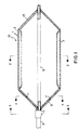
- Figure 1 is a cross-sectional view of a perfusion catheter in the inflated condition according to an embodiment of the present invention. The view is taken along the line 1-1 of Figure 2.
- Figure 2 is a cross-sectional view of the perfusion catheter shown in Figure 1 taken along the line 2-2.
- Figure 3 is an end view of the perfusion catheter showing the relative dispositions of the array of balloons, webs and channels in the proximal end of the catheter. The view is taken along the line 3-3 of Figure 1.
- Figure 4 is a cross-sectional interior view of the array of balloons taken along the line 4-4 of Figure 1.
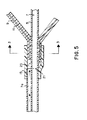
- Figure 5 is an enlarged cross-sectional view of the catheter showing particularly the fluid connection of the balloons to a lumen in the shaft.
- Referring now to Figure 1 the
catheter 10 of the present invention includes an inflatable cylindrical array 1 of radially disposed balloons 3. Each of theballoons 3 in the array 1 are in fluid flow relation with an inflation lumen disposed in ashaft 5 as will be explained hereinafter. Ahub 15 is disposed around theshaft 5 to secure the assembly. A proximalintermediate member 9 connects thehub 15 with the array ofballoons 3.Channels 11 are formed in the proximalintermediate member 9 to provide fluid passageways between aninflation lumen 7 within theshaft 5 and the interiors of theballoons 3.Inflation lumen 7 may be one of several lumens in theshaft 5 as will be explained hereinafter. - The
balloons 3 are also connected to a distalintermediate member 13. In the herein depicted embodiment theshaft 5 is disposed centrally within the array 1 to provide support for the array 1 by means of the distalintermediate member 13. In other embodiments, not shown, theshaft 5 is terminated at thehub 15 and the array 1 and the distalintermediate member 13 can be self supporting. - Inflation of the
balloons 3 causes the array 1 to expand from a folded arrangement around theshaft 5 to being spaced therefrom to provide for an interior passageway for perfusion of fluids in the bodily conduit in which the catheter is disposed. The expansion also causes the proximal and distalintermediate members balloons 3 can approximate the diameter of theshaft 5 because extremely thin walled balloons can be employed, as will be described hereinafter. - Referring now to Figure 2, the
balloons 3 are shown in an inflated state. Each of theballoons 3 haveside walls 3a, aninner wall 3b and anouter wall 3c. Theballoons 3 are disposed in a cylindrical array around an axis which can be theshaft 5. Each of theballoons 3 share acommon side wall 3a with the nextadjacent balloon 3 to enable the expansion of theballoons 3 into the cylindrical array 1 upon inflation. In Figure 2 the proximalintermediate member 9 is not shown to provide for a simplified depiction of the invention. The wall thickness of each of thewalls inner walls 3b, can be between about 0.02 and 2.0 in. With such a wide passageway bodily fluids can flow substantially unimpeded from one end of the array to the other and out without significant interruption. Thus a high flow rate of fluids can be achieved while still maintaining an adequate dilation force against the bodily conduit being treated. - Referring to Figure 3 the proximal end of the catheter assembly, that is the proximal
intermediate member 9, is shown. Each of theballoons 3 are arrayed cylindrically around the axis of the catheter. Each of theside walls 3a of theballoon 3 is an integral part of anadjacent side wall 3a of anadjacent balloon 3. Each of theballoons 3 is connected to a supply of inflation fluid by means of achannel 11 formed within the proximalintermediate member 9. Thechannels 11 are separated from each other bywebs 19 which form integral parts of the proximalintermediate member 9. In one or more locations on the proximal intermediate member 9 a slit is made betweenadjacent channels 11 to form anopening 17 through which bodily fluids can flow beneath theinner wall 3b of the array of balloons (see Figure 1). Each of thechannels 11 in the proximalintermediate member 9 terminate in a central manifold area adjacent the proximal end of the catheter as shown in Figure 5. - The distal
intermediate member 13 can be a mirror image configuration of the proximalintermediate member 9, except that there is no need to carry inflation media within channels formed therein. - In Figure 4, a cross-sectional view is shown of the interior of the proximal
intermediate member 9. Thechannels 11 are shown as dotted lines within body of thewebs 19 and as full lines within the cross-section. Each of thechannels 11 are connected to the inflation lumen of theshaft 5 so that inflation media can be delivered to the balloons.Several openings 17 are cut within the proximalintermediate member 9 when the cylindrical array of balloons is inflated. Subsequent heating of themember 9 causes the edges of the cuts to shrink to adjacent the outsides of thechannels 11 to widen theopenings 17. - To make the channels within the proximal
intermediate member 9, I have found that providing mild heating to the proximalintermediate member 9 while thechannels 11 are filled with gas at about atmospheric pressure and while gas is also forced into the inflation lumen inshaft 5 causes dilation and stretching of themember 9. The operation enables cutting of slits in theweb 17 between twoadjacent channels 11. The pressure exerted by the inflation of theballoons 3 against theside walls 3a and the mild heat causes thechannels 11 and theweb 19 to spread apart and shrink the edges to widen theopenings 17. The Figure 4 illustrates the proximalintermediate member 9 and a mirror image construction and the configuration can be embodied in the distalintermediate member 13. The openings in the distalintermediate member 13 can be substantially identical toopenings 17 in the proximalintermediate member 9. Of course there is no need for thechannels 11 to carry inflation media in the distal intermediate member. - Referring now to Figure 5 the joint between the proximal
intermediate member 9 and theshaft 5 with theinflation lumen 7 is shown.Shaft 5 can be formed with aminor lumen 7a and themajor lumen 7. Theminor lumen 7a carries the inflation fluid to thechannels 11 in the proximal intermediate member 9 (which in turn relays the fluid to the array of balloons).Lumen 7 can extend within the interior of the array to hold a guidewire that extends from the distal tip of shaft 5 (not shown, but as conventional in the art). - In a preferred embodiment,
shaft 5 is formed with two segments, one terminating at the end ofminor lumen 7a and being joined, withoutminor lumen 7a, to another shaft of similar dimensions at a joint 21. Ahub 15 of shrinkable plastic is attached to bothshaft 5 and the outside of the end of the proximalintermediate member 9. A manifold 25 is formed between the opening between the end ofminor lumen 7a and the end of proximalintermediate member 9. Inflation fluid flowing fromminor lumen 7a enters into the manifold 25 and thence tochannels 11 and ultimately to balloons 3 (not shown) to inflate them. Sealing the sections of the shaft together and sealing the shaft to thehub 15 and to the end of the proximalintermediate member 9 is in accordance with conventional techniques used in the art for sealing such elements together. - In the manufacture of the herein described balloon assembly there is a requirement to create large openings near or on both ends of the balloon to enable the blood to flow from one end to the other without impeding its progress significantly. None of the channels can be blocked or cut through because in order to obtain adequate dilation force all of the channels must be inflated. Moreover, the openings should be made as close to the balloon as possible in order to reduce resistance to flow and it is essential that the openings be made as big as possible again to reduce flow resistance.
- According to the present invention a tube is co-extruded with two or more dissimilar materials. Such materials have been described above. For example, one phase, a discrete phase, is formed of materials such as high density polyethylene. This phase can be drawn to form a tube with a plurality of channels in it. Co-extrusion of such materials is well known in the art and the shapes of the channels can be varied as desired by the operator.
- The preferred method of manufacture of the balloons is then commenced by heating the tubing in the predetermined area where the balloons are to be formed and then simultaneously pressurizing both the channels and the areas of balloon formation and the interior of the balloon, that is the area adjacent
inner walls 3b. The balloons will then expand to the desired diameter. After the balloons have been expanded, the proximal and distal intermediate members are formed by keeping each of these areas either simultaneously or sequentially inflated while not pressurizing the inside of the channels. In that way the balloons will expand but the spaces between the individual channels can be stretched and widened and one can safely cut the web between these channels to form the openings required for the flow of bodily fluids without severing the channels. A predetermined number of slits are made in the webs. The heating will cause the plastic to shrink and open the slits up to form big openings for the flow of fluids.
Claims (7)
- A multiple-balloon perfusion catheter (10) for insertion into a body conduit comprising a shaft (5) having at least one lumen (7) for delivery of a fluid inflation media and a plurality of radially disposed inflatable balloons (3), the catheter characterised by:an array (1) of the plurality of adjacent, radially disposed inflatable balloons (3) to form a closed cylindrical shape having inner (3b) and outer (3c) sides, said outer sides (3c) to engage a body conduit each of the balloons sharing a common wall with adjacent balloons;means to inflate each of said balloons (3), said means including a plurality of channels (11), each channel being in fluid flow relationship with a proximal end of one of said balloons and said lumen,at least one opening (17) between two adjacent channels(11) to allow the flow of body fluids in the body conduit from the proximal ends to within said array (1) and past the catheter (10).
- A catheter according to clain 1 characterised in that said channels (11) extend to the distal ends of each of the balloons (3) and the channels (11) are separated from each other by webs (19) whereby to form a proximal intermediate member (9) and said opening (17)is in at least one of said webs (19).
- A catheter according to claim 1 or 2 characterised in that the channels (11) and the webs (19) together form a proximal intermediate member (9).
- A catheter according to any preceding claim characterised by a distal intermediate member (13) attached to said array (1), said distal intermediate member (13) also having at least one opening in it.
- A catheter according to claim 3 and 4 characterised in that said shaft (5) extends between both said proximal and distal intermediate members (9 & 13).
- A catheter according to claim 4 or 5 characterised in that said proximal intermediate member (9) is joined to said shaft (5) by a hub (15), said hub forminq a manifold with a lumen (7) in said shaft whereby fluid flow communication between said channels (11) and said lumen is provided.
- A perfusion catheter according to any preceding claim characterised in that one end of each of said channels (11) is connected to a common manifold in fluid flow relation with said lumen (7) and the other end of each is connected to one of said balloons (3).
Applications Claiming Priority (3)
| Application Number | Priority Date | Filing Date | Title |
|---|---|---|---|
| US1776393A | 1993-02-16 | 1993-02-16 | |
| US17763 | 1993-02-16 | ||
| PCT/US1994/001300 WO1994019049A1 (en) | 1993-02-16 | 1994-02-03 | Inflatable perfusion catheter |
Publications (3)
| Publication Number | Publication Date |
|---|---|
| EP0684855A1 EP0684855A1 (en) | 1995-12-06 |
| EP0684855A4 EP0684855A4 (en) | 1996-08-07 |
| EP0684855B1 true EP0684855B1 (en) | 2001-09-05 |
Family
ID=21784408
Family Applications (1)
| Application Number | Title | Priority Date | Filing Date |
|---|---|---|---|
| EP94910103A Expired - Lifetime EP0684855B1 (en) | 1993-02-16 | 1994-02-03 | Inflatable perfusion catheter |
Country Status (7)
| Country | Link |
|---|---|
| US (2) | US5403280A (en) |
| EP (1) | EP0684855B1 (en) |
| JP (1) | JP3793993B2 (en) |
| AT (1) | ATE205100T1 (en) |
| CA (1) | CA2155195C (en) |
| DE (1) | DE69428194T2 (en) |
| WO (1) | WO1994019049A1 (en) |
Families Citing this family (88)
| Publication number | Priority date | Publication date | Assignee | Title |
|---|---|---|---|---|
| US5704913A (en) * | 1993-02-16 | 1998-01-06 | Boston Scientific Corporation | Dilation catheter and method of treatment therewith |
| US5645529A (en) * | 1993-03-11 | 1997-07-08 | C. R. Bard, Inc. | Devices for selectively directing inflation devices |
| US5755722A (en) * | 1994-12-22 | 1998-05-26 | Boston Scientific Corporation | Stent placement device with medication dispenser and method |
| FR2733143B1 (en) * | 1995-04-21 | 1997-11-07 | Nycomed Lab Sa | DEVICE FOR TEMPORARILY SHUTTERING A BODY CHANNEL, ESPECIALLY USEFUL FOR PRESSURE HEART ASSISTANCE |
| US5925054A (en) * | 1996-02-20 | 1999-07-20 | Cardiothoracic Systems, Inc. | Perfusion device for maintaining blood flow in a vessel while isolating an anastomosis |
| US5769870A (en) * | 1996-02-20 | 1998-06-23 | Cardiothoracic Systems, Inc. | Perfusion device for maintaining blood flow in a vessel while isolating an anastomosis |
| US5758731A (en) * | 1996-03-11 | 1998-06-02 | Lockheed Martin Idaho Technologies Company | Method and apparatus for advancing tethers |
| US5718684A (en) * | 1996-05-24 | 1998-02-17 | Gupta; Mukesh | Multi-lobed balloon catheter |
| US5658311A (en) * | 1996-07-05 | 1997-08-19 | Schneider (Usa) Inc. | High pressure expander bundle for large diameter stent deployment |
| US5769817A (en) * | 1997-02-28 | 1998-06-23 | Schneider (Usa) Inc. | Coextruded balloon and method of making same |
| US6132397A (en) * | 1997-05-01 | 2000-10-17 | Chase Medical Inc. | Integral aortic arch infusion clamp catheter |
| US6068608A (en) * | 1997-05-01 | 2000-05-30 | Chase Medical, Inc. | Method of using integral aortic arch infusion clamp |
| US6241699B1 (en) | 1998-07-22 | 2001-06-05 | Chase Medical, Inc. | Catheter system and method for posterior epicardial revascularization and intracardiac surgery on a beating heart |
| WO1999004836A1 (en) * | 1997-07-22 | 1999-02-04 | Chase Medical Inc. | Catheter system and method for posterior epicardial revascularization and intracardiac surgery on a beating heart |
| US6183492B1 (en) * | 1997-08-28 | 2001-02-06 | Charles C. Hart | Perfusion-isolation catheter apparatus and method |
| US5980531A (en) * | 1997-09-11 | 1999-11-09 | Schneider Inc | Stent deployment device with two balloons |
| CA2322460C (en) * | 1998-03-09 | 2004-04-27 | Fred G. Gobel | Tracheal ventilating device |
| US6136011A (en) * | 1998-07-14 | 2000-10-24 | Advanced Cardiovascular Systems, Inc. | Stent delivery system and method of use |
| US6610083B2 (en) | 1998-08-24 | 2003-08-26 | Radiant Medical, Inc. | Multiple lumen heat exchange catheters |
| US7329236B2 (en) | 1999-01-11 | 2008-02-12 | Flowmedica, Inc. | Intra-aortic renal drug delivery catheter |
| US7780628B1 (en) | 1999-01-11 | 2010-08-24 | Angiodynamics, Inc. | Apparatus and methods for treating congestive heart disease |
| US7481803B2 (en) * | 2000-11-28 | 2009-01-27 | Flowmedica, Inc. | Intra-aortic renal drug delivery catheter |
| US6471672B1 (en) | 1999-11-10 | 2002-10-29 | Scimed Life Systems | Selective high pressure dilation balloon |
| US6551304B1 (en) | 1999-12-01 | 2003-04-22 | Abbeymoor Medical, Inc. | Magnetic retrieval device and method of use |
| US6527702B2 (en) | 2000-02-01 | 2003-03-04 | Abbeymoor Medical, Inc. | Urinary flow control device and method |
| ATE308933T1 (en) * | 2000-06-23 | 2005-11-15 | Cryocath Technologies Inc | DEVICE FOR CRYOTREATMENT |
| AU2001286419A1 (en) * | 2000-08-07 | 2002-11-11 | Abbeymoor Medical, Inc. | Endourethral device and method |
| WO2002017990A2 (en) | 2000-08-31 | 2002-03-07 | Abbeymoor Medical, Inc. | Diagnostic urethral assembly & method |
| US6736828B1 (en) * | 2000-09-29 | 2004-05-18 | Scimed Life Systems, Inc. | Method for performing endoluminal fundoplication and apparatus for use in the method |
| WO2002058541A2 (en) * | 2001-01-23 | 2002-08-01 | Abbeymoor Medical, Inc. | Endourethral device & method |
| WO2002069108A2 (en) * | 2001-02-26 | 2002-09-06 | Eprivacy Group, Inc. | System and method for controlling distribution of network communications |
| US7048698B2 (en) | 2001-06-22 | 2006-05-23 | Abbeymoor Medical, Inc. | Urethral profiling device and methodology |
| US6605056B2 (en) | 2001-07-11 | 2003-08-12 | Scimed Life Systems, Inc. | Conformable balloon |
| CA2462960C (en) * | 2001-10-18 | 2010-10-12 | Abbeymoor Medical, Inc. | Endourethral device & method |
| US20040236366A1 (en) * | 2002-05-16 | 2004-11-25 | Kennedy Kenneth C. | Non-buckling balloon catheter |
| US20030236495A1 (en) * | 2002-05-16 | 2003-12-25 | Kennedy Kenneth C. | Non-buckling balloon catheter |
| US6748953B2 (en) | 2002-06-11 | 2004-06-15 | Scimed Life Systems, Inc. | Method for thermal treatment of type II endoleaks in arterial aneurysms |
| US7318815B2 (en) * | 2002-07-02 | 2008-01-15 | Qureshi Adnan I | Angioplasty device with embolic recapture mechanism for treatment of occlusive vascular diseases |
| EP1585572A4 (en) | 2002-09-20 | 2010-02-24 | Flowmedica Inc | Method and apparatus for intra aortic substance delivery to a branch vessel |
| US7097632B2 (en) * | 2002-10-28 | 2006-08-29 | Sherwood Services Ag | Automatic valve |
| US20060129092A1 (en) * | 2002-10-28 | 2006-06-15 | Sherwood Services Ag | Single lumen adapter for automatic valve |
| US7655000B2 (en) | 2003-09-26 | 2010-02-02 | Tyco Healthcare Group Lp | Urology catheter |
| US20050245899A1 (en) * | 2003-10-28 | 2005-11-03 | Swisher David R | Dual purpose adapter |
| US7261730B2 (en) * | 2003-11-14 | 2007-08-28 | Lumerx, Inc. | Phototherapy device and system |
| US8070718B2 (en) * | 2004-12-13 | 2011-12-06 | Boston Scientific Scimed, Inc. | Medical devices formed with a sacrificial structure and processes of forming the same |
| GB0613982D0 (en) | 2006-07-13 | 2006-08-23 | Shturman Leonid | Rotational atherectomy device with fluid inflatable support elements and two torque transmitting coils |
| GB0613979D0 (en) | 2006-07-13 | 2006-08-23 | Shturman Leonid | Rotational atherectomy device with solid support elements supported by fluid bearings |
| GB0613981D0 (en) | 2006-07-13 | 2006-08-23 | Shturman Leonid | |
| GB0613980D0 (en) | 2006-07-13 | 2006-08-23 | Shturman Leonid | Rotational Atherectomy Device with Fluid Inflatable Elements supported by Fluid Bearings |
| GB0623366D0 (en) | 2006-11-23 | 2007-01-03 | Shturman Leonid | Rotational atherectomy device with fluid inflatable support elements and distal protection capability |
| WO2008095052A2 (en) * | 2007-01-30 | 2008-08-07 | Loma Vista Medical, Inc., | Biological navigation device |
| US20080306441A1 (en) * | 2007-04-10 | 2008-12-11 | Wilson-Cook Medical Inc. | Non-buckling balloon catheter with spring loaded floating flexible tip |
| US8663319B2 (en) | 2007-07-23 | 2014-03-04 | Hocor Cardiovascular Technologies Llc | Methods and apparatus for percutaneous aortic valve replacement |
| US8663318B2 (en) | 2007-07-23 | 2014-03-04 | Hocor Cardiovascular Technologies Llc | Method and apparatus for percutaneous aortic valve replacement |
| US20090054922A1 (en) * | 2007-08-23 | 2009-02-26 | Broker Harshal S | Apparatus and Method for the Intravascular Control of Trauma |
| WO2009052838A1 (en) * | 2007-10-24 | 2009-04-30 | Wael Mohamed Nabil Lotfy | Perfusion balloon catheter |
| GB0722990D0 (en) | 2007-11-23 | 2008-01-02 | Shturman Leonid | Rotational atherectomy system with enhanced distal protection capability and method of use |
| US20090264820A1 (en) * | 2008-04-16 | 2009-10-22 | Abiomed, Inc. | Method and apparatus for implanting an endoluminal prosthesis such as a prosthetic valve |
| EP2644225B1 (en) | 2008-06-02 | 2020-12-23 | Loma Vista Medical, Inc. | Inflatable medical devices |
| GB0905751D0 (en) | 2009-04-03 | 2009-05-20 | Shturman Leonid | Rotational atherectomy device with distal embolic protection and method of use |
| EP2241284B1 (en) * | 2009-04-15 | 2012-09-19 | National University of Ireland, Galway | Intravasculature devices and balloons for use therewith |
| US10772717B2 (en) | 2009-05-01 | 2020-09-15 | Endologix, Inc. | Percutaneous method and device to treat dissections |
| JP2012525239A (en) | 2009-05-01 | 2012-10-22 | エンドロジックス、インク | Transcutaneous methods and devices for treating dissociation (priority information and incorporation by reference) |
| WO2011017123A2 (en) | 2009-07-27 | 2011-02-10 | Endologix, Inc. | Stent graft |
| US9820726B2 (en) * | 2009-08-24 | 2017-11-21 | St. Jude Medical Puerto Rico Llc | Polymer membrane locator with built-in stress relief structure |
| DK3441616T3 (en) | 2009-09-22 | 2023-05-30 | Ecp Entw Mbh | COMPRESSIBLE ROTOR FOR A FLUID PUMP |
| AU2010328590B2 (en) * | 2009-12-10 | 2015-09-17 | Alcon Inc. | Systems and methods for dynamic pneumatic valve driver |
| CN102858272B (en) * | 2009-12-15 | 2015-07-15 | 爱德华兹生命科学公司 | Expansion device for treatment of vascular passageways |
| US20110190727A1 (en) * | 2010-02-02 | 2011-08-04 | Boston Scientific Scimed, Inc. | Intervascular catheter, system and method |
| WO2011159733A1 (en) | 2010-06-14 | 2011-12-22 | Maquet Cardiovascular Llc | Surgical instruments, systems and methods of use |
| EP2593171B1 (en) | 2010-07-13 | 2019-08-28 | Loma Vista Medical, Inc. | Inflatable medical devices |
| US10188436B2 (en) | 2010-11-09 | 2019-01-29 | Loma Vista Medical, Inc. | Inflatable medical devices |
| WO2012068298A1 (en) | 2010-11-17 | 2012-05-24 | Endologix, Inc. | Devices and methods to treat vascular dissections |
| MX360784B (en) | 2011-01-18 | 2018-11-16 | Loma Vista Medical Inc | Inflatable medical devices. |
| US20120209375A1 (en) | 2011-02-11 | 2012-08-16 | Gilbert Madrid | Stability device for use with percutaneous delivery systems |
| CA3097484C (en) | 2012-10-18 | 2023-08-29 | Loma Vista Medical, Inc. | Reinforced inflatable medical devices |
| US9788853B2 (en) | 2014-01-15 | 2017-10-17 | Cardio Flow, Inc. | Atherectomy devices and methods |
| US10226599B2 (en) | 2014-12-23 | 2019-03-12 | C.R. Bard, Inc. | Inflatable medical device and related sheath |
| EP3294397A4 (en) * | 2015-05-13 | 2019-01-16 | Innoventions Ltd. | System for inhibiting biofilm formation on catheters, other indwelling or implantable devices and other devices |
| US10561496B2 (en) * | 2015-09-16 | 2020-02-18 | Edwards Lifesciences Corporation | Perfusion balloon designs |
| US10058371B2 (en) * | 2015-11-18 | 2018-08-28 | Medtronic Cryocath Lp | Multi-lobe balloon for cryoablation |
| US10441312B2 (en) | 2017-02-23 | 2019-10-15 | Cardio Flow, Inc. | Atherectomy devices and methods |
| US11077287B2 (en) | 2017-10-02 | 2021-08-03 | Anlvr, Llc | Non-occluding balloon for cardiovascular drug delivery |
| US10463390B1 (en) | 2018-05-24 | 2019-11-05 | Cardio Flow, Inc. | Atherectomy devices and methods |
| US11147582B2 (en) | 2018-06-14 | 2021-10-19 | Cardio Flow, Inc. | Atherectomy devices and methods |
| WO2020033260A1 (en) | 2018-08-07 | 2020-02-13 | Cardio Flow, Inc. | Atherectomy devices and methods |
| GB2587013A (en) | 2019-09-13 | 2021-03-17 | Tevar Pty Ltd | Inflatable dilatation device |
| US11253682B1 (en) * | 2021-06-17 | 2022-02-22 | Shaolong Qu | Divided tip urinary catheter with balloon inflation generated method of urine drainage |
Family Cites Families (15)
| Publication number | Priority date | Publication date | Assignee | Title |
|---|---|---|---|---|
| US4141364A (en) * | 1977-03-18 | 1979-02-27 | Jorge Schultze | Expandable endotracheal or urethral tube |
| US4183102A (en) * | 1977-09-08 | 1980-01-15 | Jacques Guiset | Inflatable prosthetic device for lining a body duct |
| CH668192A5 (en) * | 1985-11-29 | 1988-12-15 | Schneider Medintag Ag | CATHETER FOR TREATING NARROW BODIES, FOR EXAMPLE IN A BLOOD VESSEL. |
| DE3621350A1 (en) * | 1986-06-26 | 1988-01-14 | Bonzel Tassilo | DILATATION CATHETER WITH AN EXPANDABLE BALLOON |
| US4878495A (en) * | 1987-05-15 | 1989-11-07 | Joseph Grayzel | Valvuloplasty device with satellite expansion means |
| DE68917895T2 (en) * | 1988-06-06 | 1995-02-02 | Sumitomo Electric Industries | CATHETER. |
| US5108370A (en) * | 1989-10-03 | 1992-04-28 | Paul Walinsky | Perfusion balloon catheter |
| US5102416A (en) * | 1989-11-21 | 1992-04-07 | Rock John M | Vessel vector invasive catheter |
| GB8927282D0 (en) * | 1989-12-01 | 1990-01-31 | Univ Strathclyde | Vascular surgical devices |
| US4983165A (en) * | 1990-01-23 | 1991-01-08 | Loiterman David A | Guidance system for vascular catheter or the like |
| US5342301A (en) * | 1992-08-13 | 1994-08-30 | Advanced Polymers Incorporated | Multi-lumen balloons and catheters made therewith |
| US5295959A (en) * | 1992-03-13 | 1994-03-22 | Medtronic, Inc. | Autoperfusion dilatation catheter having a bonded channel |
| US5254089A (en) * | 1992-04-02 | 1993-10-19 | Boston Scientific Corp. | Medication dispensing balloon catheter |
| US5304135A (en) * | 1992-08-13 | 1994-04-19 | Cordis Corporation | Axial multi-chamber angioplasty balloon assembly |
| US5308356A (en) * | 1993-02-25 | 1994-05-03 | Blackshear Jr Perry L | Passive perfusion angioplasty catheter |
-
1994
- 1994-02-02 US US08/191,219 patent/US5403280A/en not_active Expired - Lifetime
- 1994-02-03 EP EP94910103A patent/EP0684855B1/en not_active Expired - Lifetime
- 1994-02-03 JP JP51900594A patent/JP3793993B2/en not_active Expired - Fee Related
- 1994-02-03 AT AT94910103T patent/ATE205100T1/en not_active IP Right Cessation
- 1994-02-03 CA CA002155195A patent/CA2155195C/en not_active Expired - Lifetime
- 1994-02-03 WO PCT/US1994/001300 patent/WO1994019049A1/en active IP Right Grant
- 1994-02-03 DE DE69428194T patent/DE69428194T2/en not_active Expired - Lifetime
- 1994-04-08 US US08/224,910 patent/US5458575A/en not_active Expired - Lifetime
Also Published As
| Publication number | Publication date |
|---|---|
| DE69428194D1 (en) | 2001-10-11 |
| US5458575A (en) | 1995-10-17 |
| DE69428194T2 (en) | 2002-03-28 |
| EP0684855A1 (en) | 1995-12-06 |
| CA2155195C (en) | 2006-06-06 |
| ATE205100T1 (en) | 2001-09-15 |
| JPH08506752A (en) | 1996-07-23 |
| US5403280A (en) | 1995-04-04 |
| CA2155195A1 (en) | 1994-09-01 |
| WO1994019049A1 (en) | 1994-09-01 |
| JP3793993B2 (en) | 2006-07-05 |
| EP0684855A4 (en) | 1996-08-07 |
Similar Documents
| Publication | Publication Date | Title |
|---|---|---|
| EP0684855B1 (en) | Inflatable perfusion catheter | |
| JP3561804B2 (en) | Dilatation catheter | |
| US5658311A (en) | High pressure expander bundle for large diameter stent deployment | |
| EP0799073B1 (en) | Stent placement device with medication dispenser and manufacturing method | |
| US5389314A (en) | Medication dispensing balloon catheter | |
| US5049132A (en) | Balloon catheter for delivering therapeutic agents | |
| US5792300A (en) | Perfusion catheter and striped extrusion method of manufacture | |
| US5542926A (en) | Low profile perfusion catheter | |
| EP0944408B1 (en) | Infusion balloon catheter | |
| EP0266957B1 (en) | Two balloons angiplasty catheter | |
| US7906066B2 (en) | Method of making a balloon catheter shaft having high strength and flexibility | |
| US5599306A (en) | Method and apparatus for providing external perfusion lumens on balloon catheters | |
| US5395333A (en) | Multi-lobed support balloon catheter with perfusion | |
| US4787388A (en) | Method for opening constricted regions in the cardiovascular system | |
| US8303539B2 (en) | Preform and balloon having a non-uniform thickness | |
| JP3968126B2 (en) | Low-section balloon catheter and method | |
| US5318587A (en) | Pleated balloon dilatation catheter and method of use | |
| JP2002505148A (en) | Expansion and stent delivery system for lesions at bifurcations |
Legal Events
| Date | Code | Title | Description |
|---|---|---|---|
| PUAI | Public reference made under article 153(3) epc to a published international application that has entered the european phase |
Free format text: ORIGINAL CODE: 0009012 |
|
| 17P | Request for examination filed |
Effective date: 19950811 |
|
| AK | Designated contracting states |
Kind code of ref document: A1 Designated state(s): AT BE CH DE DK ES FR GB GR IE IT LI LU MC NL PT SE |
|
| A4 | Supplementary search report drawn up and despatched |
Effective date: 19960620 |
|
| AK | Designated contracting states |
Kind code of ref document: A4 Designated state(s): AT BE CH DE DK ES FR GB GR IE IT LI LU MC NL PT SE |
|
| RAP1 | Party data changed (applicant data changed or rights of an application transferred) |
Owner name: BOSTON SCIENTIFIC CORPORATION |
|
| RAP3 | Party data changed (applicant data changed or rights of an application transferred) |
Owner name: BOSTON SCIENTIFIC CORPORATION |
|
| 17Q | First examination report despatched |
Effective date: 19981126 |
|
| GRAG | Despatch of communication of intention to grant |
Free format text: ORIGINAL CODE: EPIDOS AGRA |
|
| GRAG | Despatch of communication of intention to grant |
Free format text: ORIGINAL CODE: EPIDOS AGRA |
|
| GRAH | Despatch of communication of intention to grant a patent |
Free format text: ORIGINAL CODE: EPIDOS IGRA |
|
| GRAH | Despatch of communication of intention to grant a patent |
Free format text: ORIGINAL CODE: EPIDOS IGRA |
|
| GRAA | (expected) grant |
Free format text: ORIGINAL CODE: 0009210 |
|
| AK | Designated contracting states |
Kind code of ref document: B1 Designated state(s): AT BE CH DE DK ES FR GB GR IE IT LI LU MC NL PT SE |
|
| PG25 | Lapsed in a contracting state [announced via postgrant information from national office to epo] |
Ref country code: LI Free format text: LAPSE BECAUSE OF FAILURE TO SUBMIT A TRANSLATION OF THE DESCRIPTION OR TO PAY THE FEE WITHIN THE PRESCRIBED TIME-LIMIT Effective date: 20010905 Ref country code: IT Free format text: LAPSE BECAUSE OF FAILURE TO SUBMIT A TRANSLATION OF THE DESCRIPTION OR TO PAY THE FEE WITHIN THE PRE;WARNING: LAPSES OF ITALIAN PATENTS WITH EFFECTIVE DATE BEFORE 2007 MAY HAVE OCCURRED AT ANY TIME BEFORE 2007. THE CORRECT EFFECTIVE DATE MAY BE DIFFERENT FROM THE ONE RECORDED.SCRIBED TIME-LIMIT Effective date: 20010905 Ref country code: CH Free format text: LAPSE BECAUSE OF FAILURE TO SUBMIT A TRANSLATION OF THE DESCRIPTION OR TO PAY THE FEE WITHIN THE PRESCRIBED TIME-LIMIT Effective date: 20010905 Ref country code: BE Free format text: LAPSE BECAUSE OF FAILURE TO SUBMIT A TRANSLATION OF THE DESCRIPTION OR TO PAY THE FEE WITHIN THE PRESCRIBED TIME-LIMIT Effective date: 20010905 Ref country code: AT Free format text: LAPSE BECAUSE OF FAILURE TO SUBMIT A TRANSLATION OF THE DESCRIPTION OR TO PAY THE FEE WITHIN THE PRESCRIBED TIME-LIMIT Effective date: 20010905 |
|
| REF | Corresponds to: |
Ref document number: 205100 Country of ref document: AT Date of ref document: 20010915 Kind code of ref document: T |
|
| REG | Reference to a national code |
Ref country code: CH Ref legal event code: EP |
|
| REF | Corresponds to: |
Ref document number: 69428194 Country of ref document: DE Date of ref document: 20011011 |
|
| REG | Reference to a national code |
Ref country code: IE Ref legal event code: FG4D |
|
| PG25 | Lapsed in a contracting state [announced via postgrant information from national office to epo] |
Ref country code: SE Free format text: LAPSE BECAUSE OF FAILURE TO SUBMIT A TRANSLATION OF THE DESCRIPTION OR TO PAY THE FEE WITHIN THE PRESCRIBED TIME-LIMIT Effective date: 20011205 Ref country code: PT Free format text: LAPSE BECAUSE OF FAILURE TO SUBMIT A TRANSLATION OF THE DESCRIPTION OR TO PAY THE FEE WITHIN THE PRESCRIBED TIME-LIMIT Effective date: 20011205 Ref country code: DK Free format text: LAPSE BECAUSE OF FAILURE TO SUBMIT A TRANSLATION OF THE DESCRIPTION OR TO PAY THE FEE WITHIN THE PRESCRIBED TIME-LIMIT Effective date: 20011205 |
|
| ET | Fr: translation filed | ||
| PG25 | Lapsed in a contracting state [announced via postgrant information from national office to epo] |
Ref country code: GR Free format text: LAPSE BECAUSE OF FAILURE TO SUBMIT A TRANSLATION OF THE DESCRIPTION OR TO PAY THE FEE WITHIN THE PRESCRIBED TIME-LIMIT Effective date: 20011207 |
|
| REG | Reference to a national code |
Ref country code: GB Ref legal event code: IF02 |
|
| PG25 | Lapsed in a contracting state [announced via postgrant information from national office to epo] |
Ref country code: LU Free format text: LAPSE BECAUSE OF NON-PAYMENT OF DUE FEES Effective date: 20020203 |
|
| PG25 | Lapsed in a contracting state [announced via postgrant information from national office to epo] |
Ref country code: IE Free format text: LAPSE BECAUSE OF NON-PAYMENT OF DUE FEES Effective date: 20020204 |
|
| REG | Reference to a national code |
Ref country code: CH Ref legal event code: PL |
|
| PG25 | Lapsed in a contracting state [announced via postgrant information from national office to epo] |
Ref country code: ES Free format text: LAPSE BECAUSE OF FAILURE TO SUBMIT A TRANSLATION OF THE DESCRIPTION OR TO PAY THE FEE WITHIN THE PRESCRIBED TIME-LIMIT Effective date: 20020326 |
|
| PLBE | No opposition filed within time limit |
Free format text: ORIGINAL CODE: 0009261 |
|
| STAA | Information on the status of an ep patent application or granted ep patent |
Free format text: STATUS: NO OPPOSITION FILED WITHIN TIME LIMIT |
|
| 26N | No opposition filed | ||
| PG25 | Lapsed in a contracting state [announced via postgrant information from national office to epo] |
Ref country code: MC Free format text: LAPSE BECAUSE OF NON-PAYMENT OF DUE FEES Effective date: 20020901 |
|
| REG | Reference to a national code |
Ref country code: IE Ref legal event code: MM4A |
|
| PGFP | Annual fee paid to national office [announced via postgrant information from national office to epo] |
Ref country code: NL Payment date: 20090210 Year of fee payment: 16 |
|
| PGFP | Annual fee paid to national office [announced via postgrant information from national office to epo] |
Ref country code: GB Payment date: 20090106 Year of fee payment: 16 |
|
| PGFP | Annual fee paid to national office [announced via postgrant information from national office to epo] |
Ref country code: FR Payment date: 20090206 Year of fee payment: 16 |
|
| REG | Reference to a national code |
Ref country code: NL Ref legal event code: V1 Effective date: 20100901 |
|
| GBPC | Gb: european patent ceased through non-payment of renewal fee |
Effective date: 20100203 |
|
| REG | Reference to a national code |
Ref country code: FR Ref legal event code: ST Effective date: 20101029 |
|
| PG25 | Lapsed in a contracting state [announced via postgrant information from national office to epo] |
Ref country code: NL Free format text: LAPSE BECAUSE OF NON-PAYMENT OF DUE FEES Effective date: 20100901 Ref country code: FR Free format text: LAPSE BECAUSE OF NON-PAYMENT OF DUE FEES Effective date: 20100301 |
|
| PG25 | Lapsed in a contracting state [announced via postgrant information from national office to epo] |
Ref country code: GB Free format text: LAPSE BECAUSE OF NON-PAYMENT OF DUE FEES Effective date: 20100203 |
|
| PGFP | Annual fee paid to national office [announced via postgrant information from national office to epo] |
Ref country code: DE Payment date: 20130131 Year of fee payment: 20 |
|
| REG | Reference to a national code |
Ref country code: DE Ref legal event code: R071 Ref document number: 69428194 Country of ref document: DE |
|
| PG25 | Lapsed in a contracting state [announced via postgrant information from national office to epo] |
Ref country code: DE Free format text: LAPSE BECAUSE OF EXPIRATION OF PROTECTION Effective date: 20140204 |